EP3196395B1 - Porte dotée d'une poignée - Google Patents
Porte dotée d'une poignée Download PDFInfo
- Publication number
- EP3196395B1 EP3196395B1 EP17158467.5A EP17158467A EP3196395B1 EP 3196395 B1 EP3196395 B1 EP 3196395B1 EP 17158467 A EP17158467 A EP 17158467A EP 3196395 B1 EP3196395 B1 EP 3196395B1
- Authority
- EP
- European Patent Office
- Prior art keywords
- profile
- handle
- groove
- door
- sash
- Prior art date
- Legal status (The legal status is an assumption and is not a legal conclusion. Google has not performed a legal analysis and makes no representation as to the accuracy of the status listed.)
- Active
Links
Images


Classifications
-
- E—FIXED CONSTRUCTIONS
- E06—DOORS, WINDOWS, SHUTTERS, OR ROLLER BLINDS IN GENERAL; LADDERS
- E06B—FIXED OR MOVABLE CLOSURES FOR OPENINGS IN BUILDINGS, VEHICLES, FENCES OR LIKE ENCLOSURES IN GENERAL, e.g. DOORS, WINDOWS, BLINDS, GATES
- E06B3/00—Window sashes, door leaves, or like elements for closing wall or like openings; Layout of fixed or moving closures, e.g. windows in wall or like openings; Features of rigidly-mounted outer frames relating to the mounting of wing frames
- E06B3/70—Door leaves
- E06B3/82—Flush doors, i.e. with completely flat surface
-
- E—FIXED CONSTRUCTIONS
- E05—LOCKS; KEYS; WINDOW OR DOOR FITTINGS; SAFES
- E05B—LOCKS; ACCESSORIES THEREFOR; HANDCUFFS
- E05B1/00—Knobs or handles for wings; Knobs, handles, or press buttons for locks or latches on wings
- E05B1/0015—Knobs or handles which do not operate the bolt or lock, e.g. non-movable; Mounting thereof
-
- E—FIXED CONSTRUCTIONS
- E05—LOCKS; KEYS; WINDOW OR DOOR FITTINGS; SAFES
- E05B—LOCKS; ACCESSORIES THEREFOR; HANDCUFFS
- E05B17/00—Accessories in connection with locks
- E05B17/0075—Insulating, e.g. for limiting heat transfer; Increasing fire-resistance of locks
-
- E—FIXED CONSTRUCTIONS
- E06—DOORS, WINDOWS, SHUTTERS, OR ROLLER BLINDS IN GENERAL; LADDERS
- E06B—FIXED OR MOVABLE CLOSURES FOR OPENINGS IN BUILDINGS, VEHICLES, FENCES OR LIKE ENCLOSURES IN GENERAL, e.g. DOORS, WINDOWS, BLINDS, GATES
- E06B3/00—Window sashes, door leaves, or like elements for closing wall or like openings; Layout of fixed or moving closures, e.g. windows in wall or like openings; Features of rigidly-mounted outer frames relating to the mounting of wing frames
- E06B3/04—Wing frames not characterised by the manner of movement
- E06B3/263—Frames with special provision for insulation
- E06B3/26301—Frames with special provision for insulation with prefabricated insulating strips between two metal section members
- E06B3/26303—Frames with special provision for insulation with prefabricated insulating strips between two metal section members with thin strips, e.g. defining a hollow space between the metal section members
-
- E—FIXED CONSTRUCTIONS
- E06—DOORS, WINDOWS, SHUTTERS, OR ROLLER BLINDS IN GENERAL; LADDERS
- E06B—FIXED OR MOVABLE CLOSURES FOR OPENINGS IN BUILDINGS, VEHICLES, FENCES OR LIKE ENCLOSURES IN GENERAL, e.g. DOORS, WINDOWS, BLINDS, GATES
- E06B3/00—Window sashes, door leaves, or like elements for closing wall or like openings; Layout of fixed or moving closures, e.g. windows in wall or like openings; Features of rigidly-mounted outer frames relating to the mounting of wing frames
- E06B3/04—Wing frames not characterised by the manner of movement
- E06B3/263—Frames with special provision for insulation
- E06B3/26301—Frames with special provision for insulation with prefabricated insulating strips between two metal section members
- E06B3/26305—Connection details
-
- E—FIXED CONSTRUCTIONS
- E06—DOORS, WINDOWS, SHUTTERS, OR ROLLER BLINDS IN GENERAL; LADDERS
- E06B—FIXED OR MOVABLE CLOSURES FOR OPENINGS IN BUILDINGS, VEHICLES, FENCES OR LIKE ENCLOSURES IN GENERAL, e.g. DOORS, WINDOWS, BLINDS, GATES
- E06B3/00—Window sashes, door leaves, or like elements for closing wall or like openings; Layout of fixed or moving closures, e.g. windows in wall or like openings; Features of rigidly-mounted outer frames relating to the mounting of wing frames
- E06B3/04—Wing frames not characterised by the manner of movement
- E06B3/263—Frames with special provision for insulation
- E06B3/26343—Frames with special provision for insulation with two or more separate insulating zones alternating with metal section members
-
- E—FIXED CONSTRUCTIONS
- E06—DOORS, WINDOWS, SHUTTERS, OR ROLLER BLINDS IN GENERAL; LADDERS
- E06B—FIXED OR MOVABLE CLOSURES FOR OPENINGS IN BUILDINGS, VEHICLES, FENCES OR LIKE ENCLOSURES IN GENERAL, e.g. DOORS, WINDOWS, BLINDS, GATES
- E06B3/00—Window sashes, door leaves, or like elements for closing wall or like openings; Layout of fixed or moving closures, e.g. windows in wall or like openings; Features of rigidly-mounted outer frames relating to the mounting of wing frames
- E06B3/04—Wing frames not characterised by the manner of movement
- E06B3/263—Frames with special provision for insulation
- E06B3/26301—Frames with special provision for insulation with prefabricated insulating strips between two metal section members
- E06B3/26305—Connection details
- E06B2003/26316—Disconnectable connections or permitting shifting between the sections
-
- E—FIXED CONSTRUCTIONS
- E06—DOORS, WINDOWS, SHUTTERS, OR ROLLER BLINDS IN GENERAL; LADDERS
- E06B—FIXED OR MOVABLE CLOSURES FOR OPENINGS IN BUILDINGS, VEHICLES, FENCES OR LIKE ENCLOSURES IN GENERAL, e.g. DOORS, WINDOWS, BLINDS, GATES
- E06B3/00—Window sashes, door leaves, or like elements for closing wall or like openings; Layout of fixed or moving closures, e.g. windows in wall or like openings; Features of rigidly-mounted outer frames relating to the mounting of wing frames
- E06B3/04—Wing frames not characterised by the manner of movement
- E06B3/263—Frames with special provision for insulation
- E06B2003/26349—Details of insulating strips
- E06B2003/2635—Specific form characteristics
- E06B2003/26365—Composed of several similar parts positioned one after the other
-
- E—FIXED CONSTRUCTIONS
- E06—DOORS, WINDOWS, SHUTTERS, OR ROLLER BLINDS IN GENERAL; LADDERS
- E06B—FIXED OR MOVABLE CLOSURES FOR OPENINGS IN BUILDINGS, VEHICLES, FENCES OR LIKE ENCLOSURES IN GENERAL, e.g. DOORS, WINDOWS, BLINDS, GATES
- E06B3/00—Window sashes, door leaves, or like elements for closing wall or like openings; Layout of fixed or moving closures, e.g. windows in wall or like openings; Features of rigidly-mounted outer frames relating to the mounting of wing frames
- E06B3/04—Wing frames not characterised by the manner of movement
- E06B3/263—Frames with special provision for insulation
- E06B2003/26349—Details of insulating strips
- E06B2003/26387—Performing extra functions
- E06B2003/26389—Holding sealing strips or forming sealing abutments
-
- E—FIXED CONSTRUCTIONS
- E06—DOORS, WINDOWS, SHUTTERS, OR ROLLER BLINDS IN GENERAL; LADDERS
- E06B—FIXED OR MOVABLE CLOSURES FOR OPENINGS IN BUILDINGS, VEHICLES, FENCES OR LIKE ENCLOSURES IN GENERAL, e.g. DOORS, WINDOWS, BLINDS, GATES
- E06B3/00—Window sashes, door leaves, or like elements for closing wall or like openings; Layout of fixed or moving closures, e.g. windows in wall or like openings; Features of rigidly-mounted outer frames relating to the mounting of wing frames
- E06B3/70—Door leaves
- E06B2003/7046—Door leaves with provisions for locks, hinges or other fittings
Definitions
- the present invention relates to a door or a window with a handle profile according to the preamble of claim 1.
- a door is out of the FR 2 951 769 A1 known.
- the door handle stands out of the plane he door. The statics of the door is adversely affected by the handle.
- FR 2 951 769 A1 discloses all features of the preamble of claim 1.
- U1 discloses a door having a frame on which a wing is rotatably mounted.
- the wing has a handle bar, which is arranged on the outside of the wing and which is embedded in the wing.
- embedded here means that the handle bar is surrounded by an insulating material, in particular a foamed plastic and is formed by formed with undercut grooves in which the insulating material, positively held in the insulating material.
- the handle bar is thus attached only at their end faces on a circumferential inner frame of the wing.
- Such an arrangement or embedding has a detrimental effect on the rigidity of the handle bar, since the handle bar is deformed elastically by actuation forces virtually every time the handle bar is actuated.
- the door has a wing or, in the case of a door, a door leaf having front and rear fillings integrated into the wing and at its peripheral edges are attached by soffit parts to each other.
- the front and rear panels form a front surface and a rear surface of the door, respectively, the handle extending from the front surface to the rear surface of the wing and configured to allow users to open / close the door.
- the handle is a substantially straight elongate metallic profile that extends over substantially an entire extent of the front and rear surfaces, thus dividing the wing into separate wing segments which extend on opposite sides of the handle.
- a disadvantage of the solution after the DE 60 2005 001 154 T2 is the bad thermal insulation.
- there is a considerable manufacturing effort since in the wing production relatively many items are to be added.
- the statics of the door is adversely affected by the handle.
- the invention therefore has the task of improving the generic state of the art.
- the present invention solves this problem by the subject matter of claim 1.
- the handle profile on a handle recess profile which has a hollow chamber.
- the recessed grip profile is preferably a metallic recessed grip profile.
- the grip profile is designed as a thermally insulated composite profile.
- the handle profile Due to the structure of the handle profile as a thermally insulated composite profile, wherein the handle profile is composed of several closed part profiles, which are interconnected by insulating webs, the resistance to deformation of the handle profile is increased, so that the handle profile consequently has a high rigidity.
- the grip profile or the grip profile has an opening for a profile closure cylinder or a profile closure cylinder. This makes it possible in an advantageous manner to use the handle profile for the production of a casement Holmes.
- the handle profile in his recessed grip on one or more bulbs, such. one or more LEDs.
- the grip profile and its surroundings can be illuminated in the dark in an advantageous manner, so that no additional illumination of the door or an entrance area is required to open the door with a key.
- the handle profile on its side facing the filling has a compatible or the same topology - i. a compatible or preferably even the same geometry with the same functional areas as grooves, etc. - has, as the adjoining it sash composite profile on its side facing the filling.
- various fillings e.g. to install an insulating glazing or a sandwich panel with a heat-insulating core made of foamed plastic on the handle profile, so that the handle profile with respect to various fillings is also universally applicable, as a corresponding wing frame composite profile.
- the handle profile has the same width as the wing frame composite profile.
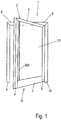
- the Fig. 1 shows a door 1, which has a wing with a sash 2 and a frame 3. This is merely an example to understand. Alternatively to the in Fig. 1 1, the present invention can also be used in windows or the like. If the term "door” is used below, it can therefore also be replaced by a term window.
- a corner joint of two vertically or vertically aligned wing frame beams 4, 5 with an upper horizontal wing frame spar 6 an at least U-shaped (ie open on one side) frame of similar profiles is created.
- a lower horizontal wing frame spar 7 is here as one to the rest Wing frame members 4, 5, 6 geometrically different profile formed.
- the casement 2 can also be made circumferentially closed from wing frame beams 4, 5, 6, 7, which are each made of a single profile.
- the frame 3 of this door 1 has frame frame spars 8, 9, 10. Individual or all of the spars may be formed as thermally insulated composite profiles.
- the wing 12 also has a grip profile 300 according to the invention.
- the filling 11 may e.g. an insulating glazing or a sandwich panel with a heat-insulating core made of foamed plastic.
- the handle profile 300 is disposed parallel to the vertical sash bars 4, 5 and has a length that is identical to the dimension of the filling 11 in its vertical extension direction.
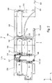
- Fig. 2 is a a door 1 with a wing frame composite profile 100 and a frame composite profile 200, and the handle profile 300 and the filling 11 after Fig. 1 shown in section. For simplicity, only the part of the door 1 with the handle profile 300 is shown.
- a wing frame composite profile 100 and a frame composite profile 200 having in each case two metallic outer profiles 101, 102 or 201, 202 and in each case a metallic center profile 103 or 203 will be described.
- the casement composite profile 100 and / or the frame composite profile 200 may be constructed without the metal center section 103 or 203, so that in each case the two metallic outer profiles 101, 102 and 201, 202 are connected to each other only via a Isolierstecreatee ,
- the frame composite profile 200 and the handle profile 300 own reference numeric number ranges are used to identify analogous characteristics in the individual composite profiles 100, 200, 300 accordingly. This results however, in the frame composite profile 200 and the handle profile 300, a non-consecutive numbering of the reference numerals.
- the sash composite profile 100 is detailed in FIG Fig. 3 and the frame composite profile 200 is detailed in FIG Fig. 4 so that the following description also applies to the illustrations in Fig. 3 or in Fig. 4 refers.
- the sash composite profile 100 (see Fig. 2 and 3 ) has a first metallic outer profile 101, in which here at least one hollow chamber 104 is formed, and a metallic center profile 103, in which also preferably at least one hollow chamber 105 is formed.
- the hollow chamber 105 is designed so that it can accommodate a lock case (not shown here), via which the door 1 can be locked.
- the first metallic outer profile 101 is connected to the metallic center profile 103 via at least one or more first insulating webs (aligned parallel here) 106, 107. These insulating webs 106, 107 between the first metallic outer profile 101 and the metallic center profile 103 form a first insulating land zone I or plane.
- the first metallic outer profile 101 also has, on its side facing away from the first insulating land zone I, a groove 108.
- the metallic center profile 103 has in each case on its sides, each in the x-direction (see coordinate system in Fig. 2 and Fig. 3 ), each having a groove 109, 110 with an undercut, wherein the grooves 109, 110 is here each designed as a groove 109, 110 with a substantially T-shaped cross-section.
- a cover plate 111 is positioned and fixed, which has a with the groove 109 geometrically corresponding, integrally formed on the cover plate 111 foot 112 which engages in the groove 109 and is snapped into the groove 109.
- the geometric configuration of the undercut of the grooves 109, 110 may also be performed differently than T-shaped.
- the metallic center profile 103 is connected to a second metallic outer profile 102, in which preferably at least one hollow chamber 113 is formed, via at least one or more second insulating webs (aligned parallel here) 114, 115 connected.
- This insulating webs 114, 115 between the metallic center section 103 and the second metallic outer profile 102 form a second insulating land zone II or plane.
- the insulating webs 106, 107, 114, 115 have here-by way of example-no hollow chambers. Alternatively, however, the insulating webs 106, 107, 114, 115 may also have one or more hollow chambers or the insulating webs 106, 107, 114, 115 may be summarized by transverse webs to a kind of higher-level insulating profile.
- the insulating webs 106, 107, 114, 115 are here-by way of example-arranged in a plane. Alternatively, it is also possible for the insulating webs 106, 107, 114, 115 to be offset horizontally relative to each other or vertically offset from one another. Likewise, a diagonal orientation of the insulating webs 106, 107, 114, 115 is possible.
- the first insulating land zone I which is formed between the first metallic outer profile 101 and the metallic center profile 103 by the insulating webs 106, 107, has a hollow chamber 116.
- the second insulating land zone II formed between the metallic center profile 103 and the second metal outer profile 102 by the insulating webs 114, 115 also has a hollow chamber 117.
- the insulating webs 106, 107, 114, 115 are web-shaped in cross-section.
- the insulating webs 106, 107 of the first insulating land zone I each have two thickened end sections 118.
- each of the end sections 118 preferably engages in a corresponding groove 119, which here is formed by a respective one of the metal profiles 101, 103.
- the respective end portion 118 preferably has a trapezoidal or triangular or wedge-shaped or L-shaped or rectangular cross-section.
- the respective groove 119 accordingly has a cross section with a corresponding cross section.
- the respective end portions 118 are set in the respective groove 119 by a forming process.
- the respective end portion 118 of the insulating webs 106, 107 in the x and y directions with respect to the coordinate system in Fig. 2 and Fig. 3 established.
- the respective end portion 118 is also by a wire having an outer structure, such as knurling (not shown here) or other suitable joining method in addition in the z-direction with respect to the coordinate system in Fig. 2 and Fig. 3 or set in profile direction, so that in each case a shear-resistant connection is formed.
- the insulating web 107 of the first insulating land zone I has a groove 120 with an undercut, wherein the groove 120 is designed here as a groove with a T-shaped cross-section.
- the groove 120 here a sealing profile 121 is positioned and fixed, which has a with the groove 120 geometrically corresponding, integrally formed on the sealing profile 121 foot 122 which engages in the groove 120 and snapped into the groove 120.
- the geometric design of the undercut of the groove 120 may also be performed differently than T-shaped.
- each of the end sections 118 preferably engages in a corresponding groove 119, which here-by way of example-is formed by the metallic center section 103.
- the groove 119 may also be formed by the second outer profile 102.
- the respective end portion 118 preferably has a trapezoidal or triangular or wedge-shaped or L-shaped or rectangular cross-section.
- the respective groove 119 accordingly has a cross section with a corresponding cross section.
- the respective end portions 118 are fixed in the respective groove 119 by a forming process.
- the respective end portion 118 of the insulating webs 114, 115 in the x and y directions with respect to the coordinate system in Fig. 2 and Fig. 3 established.
- the respective end portion 118 is also in the z-direction by a wire having an outer structure, such as a knurling (not shown here) or another suitable joining method on the coordinate system in Fig. 2 and Fig. 3 or set in profile direction, so that in each case a shear-resistant connection is formed.
- the insulating webs 114, 115 also have here on their side facing away from the respective end portion 118 each a Kederwulst 123 and a Kederfahne 124.
- the second metallic outer profile 102 in each case has a groove 125 with a corresponding cross-sectional geometry, so that the respective Kederwulst 123 engages in the respective groove 125 and the respective Kederfahne 124 is led out of the groove 125.
- a sliding guide is formed.
- the shear strength in the sliding guide orthogonal to the cross-sectional plane of the composite profile may, but need not go to zero.
- Such a sliding guide is colloquially referred to as a "push-soft connection".
- the metallic center profile 103 may form the groove 125.
- the insulating webs 114 and 115 may also each have a Kederwulst 123 and a Kederfahne 124 at its two ends. Accordingly, in this case, both the metallic center profile 103 and the second metal outer profile 102 respectively form the groove 125.
- the insulating webs 114 and 115 also in each case a Kederwulst 123 and a Kederfahne 124 bez. have a groove 125 so that each Isoliersteg 114, 115 each result in two Isolierstegabexcellente, each one Isolierstegabhow the Kederwulst 123 and the Kederfahne 124 and the other Isolierstegabhow the groove 125 has.
- the Isolierstegabroughe each have an end portion 118 and the respective metal profiles 102, 103 on a respective end portion 118 corresponding groove 119
- the insulating web 115 has a groove 120 with an undercut, wherein the groove 120 is designed here as a groove with a T-shaped cross-section.
- the groove 120 here is a cover plate 126 is positioned and fixed, which has a with the groove 120 geometrically corresponding, integrally formed on the cover plate 126 foot 127 which engages in the groove 120 and is snapped into the groove 120.
- the geometric Design of the undercut of the groove 120 may also be performed differently than T-shaped.
- the shear strength of the sliding guide is chosen such that a displacement of at least two elements in the Isolierstegzone relative to each other due to dilation is possible without causing a tilting of the sliding guide and thereby adjusts a bending of the sash composite profile 100.
- the second metallic outer profile 102 has, on its side facing away from the second insulating land zone II, two in each case with respect to the coordinate system in FIG Fig. 2 and Fig. 3 in the x-direction extending webs 128, 129 with free end.
- the two webs 128, 129 each have at their ends a groove 130 or 131 with an undercut for receiving a sealing profile 132 or another wing component - in this case the grip profile 300 or a grip profile 302 - on.
- the groove 130 or 131 has here in each case a T-shaped cross-section, alternatively, the groove 130 or 131 may also have another suitable cross-sectional geometry to realize an undercut.
- the second metallic outer profile 102 and the metallic center profile 103 may also have an opening for a profile lock cylinder (not shown here).
- the metallic outer profiles 101, 102 and the metallic center profile 103 are preferably produced as extruded aluminum profiles. Alternatively, the production is also possible from a different material such as steel and / or another manufacturing method.
- the insulating webs 106, 107, 114, 115 are made of a plastic material, such as polyamides (PA66, PA6, PPA), polyester (PET, PBT), polyolefins (PP) or polyvinyl chloride (PVC), so that each one extensive thermal Separation between the metal profiles 101, 102, 103 is achieved.
- the frame composite profile 200 has a similar or similar structure as the sash composite profile 100. Therefore, in order to avoid repetition, only deviations and additions to the wing frame composite profile 100 will be described below.
- the frame composite profile 200 (see Fig. 2 and Fig. 4 ) also has two insulating land zones III, IV. Notwithstanding the insulating webs 106, 107 of the first insulating land zone I of the sash composite profile 100, the window frame composite profile 200 in the first insulating land zone III insulating webs 206, 207, which are arranged vertically offset from one another.
- the first metallic outer profile 201 of the frame composite profile 200 has on its side facing away from the first insulating land zone II a with respect to the coordinate system in Fig. 2 and Fig. 4 in the x-direction extending ridge 233.
- the web 233 has at its end a groove 234 with an undercut for receiving a sealing profile 221.
- the groove 234 here has a T-shaped cross-section, alternatively, the groove 234 may also have another suitable cross-sectional geometry to realize an undercut.
- the insulating web 207 has a groove 220 with an undercut, wherein the groove 220 is designed here as a groove with T-shaped cross-section.
- the sealing profile 221 is positioned and fixed, which has a with the groove 220 geometrically corresponding, integrally formed on the sealing profile 221 foot 222 which engages in the groove 220 and snapped into the groove.
- the geometric design of the undercut of the groove 220 may also be performed differently than T-shaped.
- the sealing profiles 121, 132, 221 seal a rebate space 400 against the environment formed between the frame composite profile 200 and the wing frame composite profile 100 in the closed state of the door 1.
- the sealing profiles 121 and 221 are in an operative connection, while the sealing profile 132 is in operative connection with the second metallic outer profile 202 of the frame composite profile 200.
- the sealing profile 221 is also with the first metallic outer profile 101 of the sash composite profile 100 in operative connection, so that the sealing profile 221 has two sealing levels.
- the metallic center profile 203 of the frame composite profile 200 different from the metallic center profile 103 of the sash composite profile 100 on only one side, one in the x direction (see coordinate system in Fig. 2 and Fig. 4 ) aligned groove 209 having an undercut, wherein the groove 209 is designed here as a groove with T-shaped cross-section.
- a cover plate 211 is positioned and fixed, which has a with the groove 209 geometrically corresponding, integrally formed on the cover plate 211 foot 212 which engages in the groove 209 and is snapped into the groove 209.
- the geometric design of the undercut of the groove 209 may also be designed differently than T-shaped.
- the frame composite profile 200 has insulating ribs 206, 207 in its second insulating strip zone IV.
- the two insulating webs 206, 207 of the second insulating land zone IV each have at their two ends a thickened end portion 218.
- each of the end sections 218 preferably engages in a corresponding groove 219, which here is formed by a respective one of the metal profiles 202, 203.
- the respective end portion 218 preferably has a trapezoidal or triangular or wedge-shaped or L-shaped or rectangular cross section.
- the respective groove 219 accordingly has a cross section with a corresponding cross section.
- the insulating webs 206, 207 unlike the insulating webs 114, 115 of the second insulating web zone II of the sash composite profile 100, do not slide with the second metal outer profile 202 of the window frame composite profile 200 or the metallic center profile 203 of the window frame composite profile 200.
- the two insulating webs 206, 207 of the second insulating land zone IV of the frame composite profile 200 are here slightly offset from one another vertically.
- the insulating webs 206, 207 are each offset horizontally from one another or arranged in a plane.
- a diagonal orientation of the insulating webs 206, 207 is possible.
- the handle profile 300 (see Fig. 2 and 5 ) is designed in a particularly advantageous manner as a heat-insulating composite profile that has the same width B as the wing frame composite profile 100 (see Fig. 2 ).
- the grip profile 300 accordingly has a metallic outer profile 301, in which at least one hollow chamber 304 is formed here, and a metallic grip profile 302, in which also preferably at least one hollow chamber 313 is formed.
- the metallic outer profile 301 has a groove 308 into which, e.g. a glass retaining strip (not shown here) can be used. This functionality is used when the filling 11 of the wing 12 is e.g. a glazing (not shown here) is provided.
- the hollow chamber 313 of the metallic recessed grip profile 302 can be designed so that it can receive a lock case (not shown here). This makes it possible to produce a vertical wing frame spar 4 alternatively from a handle profile 300.
- the metallic outer profile 301 is connected to the metallic recessed grip profile 302 via at least one or more first insulating webs (aligned parallel here) 306. These insulating webs 306 between the first metallic outer profile 301 and the metallic recessed grip profile 302 form a Isolierstegzone V or - level. Through the hollow chambers 304 and 313 results in each case a metal profile 301, 302 with a relatively high surface moment 2nd Order or area moment of inertia.
- the grip profile may also have two insulating web zones or planes, in which case the insulating web zone V is adjoined by a further metal profile which is connected to the recessed grip profile 302 via a second insulating web zone or plane.
- the metallic outer profile 301 and the recessed grip profile 302 are preferably produced as extruded aluminum profiles. Alternatively, the production is also possible from a different material such as steel and / or another manufacturing method.
- the insulating webs 306 are made of a plastic material, such as polyamides (PA66, PA6, PPA), polyester (PET, PBT), polyolefins (PP) or polyvinyl chloride (PVC), so that in each case a substantial thermal separation between the metal profiles 301 and 302 is reached.
- the metallic grip profile 302 has on its wing frame composite profile 100 side facing in the x direction (see coordinate system in Fig. 2 and Fig. 5 ), a web 335 which engages in the groove 110 with undercut of the metallic center profile 103 of the sash composite profile 100 and is defined by the undercut of the groove 110 in the groove 110.
- the recessed grip profile 302 or the grip profile 300 in the x-direction and in the y-direction (see coordinate system in FIG Fig. 2 and Fig. 5 ) fixed positively.
- the metallic grip profile 302 also has on its side facing away from the wing frame composite profile 100, which in the x direction (see coordinate system in Fig. 2 and Fig. 5 ), a groove 310 with undercut on.
- the metallic grip profile 302 also has a recessed grip 336.
- the recessed grip 336 has on its side facing the hollow chamber 313 an arcuately shaped profile web 337.
- the arc of arc-shaped profile land 337 may be a circular arc or a portion of another curve, such as a curve. to be a section of a function graph.
- the recessed grip 336 is open to the outside A of the wing 12 of the door 1, so that the arcuately shaped profile web 337 limits the recessed grip 336 in the direction of the inside of the wing 12 or the door 1.
- In the arcuately shaped profile web 337 may also have an opening for receiving a profile closing cylinder (not shown here).
- the recessed grip 336 also has an undercut, which is realized by an angled profile web 338.
- the angled profile web 338 has at its free end 339 a T-shaped cross-sectional geometry.
- the T-shaped cross-sectional geometry of the free end 339 engages in the undercut groove 130 with corresponding cross-sectional geometry, which forms the second metallic outer profile 102 of the wing frame composite profile 100.
- the recessed grip profile 302 or the grip profile 300 in the x-direction and in the y-direction (see coordinate system in FIG Fig. 2 and Fig. 5 ) fixed positively.
- the handle profile 300 is advantageously mounted or mounted on the vertical sash profile rail spar 4 and the sash composite profile 100. This results in a particularly advantageous, rigid connection between the sash composite profile 100 and the sash frame member 4 formed therefrom and the handle profile 300, which act on the actuation forces or actuating moments acting on the handle profile 300 and on the door 1 and the resulting elastic deformations permanently endure without damage.
- handle profile 300 may be formed over the metallic center profile 103 of the sash composite profile 100 by fasteners, such as e.g. Screws are additionally fastened (not shown here).
- the grip profile 300 at the bottom of its recessed grip 336 can have one or more light sources, such as e.g. have one or more LEDs (not shown here).
- the recessed grip 336 and thus at least partially the profiled cylinder can be illuminated in an advantageous manner at night, so that no additional illumination of the door 1 or an entrance area is required to open the door 1 with a key.
- the recessed grip profile 302 also has - analogous to the second metallic outer profile 102 of the sash composite profile 100- on its side facing away from the Isolierstegzone V side, a with respect to the coordinate system in Fig. 2 and Fig. 5 in the x-direction extending web 328 with a free end.
- the web 328 has at its end a groove 330 with an undercut for receiving a sealing profile with which, for example, a folding region of a glazing is sealed when a glazing is provided for the filling 11 of the wing 12.
- the groove 330 here has a T-shaped cross-section, alternatively, the groove 330 may also have another suitable cross-sectional geometry in order to realize an undercut.
- the web 328 with free end covers the edge of the filling 11, for example, a sandwich panel with a heat-insulating core made of foamed plastic.
- the handle profile 300 thus has the same topology on its side facing the filling 12, as the sash composite profile 100, so that the connection topology or geometry of the filling 12 always remains the same, regardless of whether the filling 12 with the sash composite profile 100 or with the Handle profile 300 is connected.
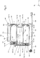
- the door 1a after Fig. 4 two additional spars 13, 14, each spaced from each other parallel to the upper horizontal wing frame spar 6 of the door 1a are arranged so that the filling of the door 1a in several, here three filling zones 11a, 11b, 11c is divided. In other words, the filling zones 11a, 11b, 11c are separated from the bars 14, 15.
- the three filling zones 11a, 11b, 11c of the door 1a are made approximately the same width, here by the term “wide” or “width” is meant an extension parallel to the vertical sash 4.5 of the door 1.
- one or two or all filling zone (s) 11a, 11b, 11c may each have different widths.
- the handle profile 300 is here parallel to the vertical sash bars 4, 5 of the door 1 and has a length which is identical to the dimension of the filling 11b in its vertical extension direction or with its width.
- the handle profile 300 may also be arranged parallel to one of the spars 13, 14 or parallel to the horizontal sash spar 6, wherein the spars 13, 14 may also be arranged diagonally in the sash 2.
Landscapes
- Engineering & Computer Science (AREA)
- Civil Engineering (AREA)
- Structural Engineering (AREA)
- Physics & Mathematics (AREA)
- Thermal Sciences (AREA)
- Wing Frames And Configurations (AREA)
Claims (16)
- Porte (1) ou fenêtre aveca. un châssis battant (2) etb. un châssis dormant (3),c. le châssis battant (2) possédant des longerons de châssis battant (4, 5, 6,7),d. les longerons de châssis battant (4, 5, 6, 7) formant un battant (12) avec un panneau (11) ete. le battant (12) présentant en outre au moins un profilé de poignée (300),f. lequel profilé de poignée (300) est de préférence disposé parallèlement à l'un des longerons du châssis battant (4, 5, 6, 7),g. lequel profilé de poignée (300) est fixé à un profilé composite de châssis battant (100),
caractérisée en ce queh. le profilé de poignée (300) présente une poignée en creux (336) qui est ouverte vers le côté extérieur (A) du battant (12) de la porte (1). - Porte (1) ou fenêtre selon la revendication 1, caractérisée en ce que le profilé de poignée présente un profilé de poignée en creux (302) qui présente un compartiment creux (313).
- Porte (1) ou fenêtre selon la revendication 2, caractérisée en ce que le profilé de poignée en creux (302) est un profilé de poignée en creux métallique.
- Porte (1) ou fenêtre selon l'une des revendications 1, 2 ou 3, caractérisée en ce que le profilé de poignée (300) est un profilé extérieur métallique (301).
- Porte (1) ou fenêtre selon l'une des revendications 2, 3 ou 4, caractérisée en ce qu'au moins un compartiment creux (304) est formé dans le profilé extérieur métallique (301).
- Porte (1) ou fenêtre selon l'une des revendications précédentes, caractérisée en ce que le profilé de poignée en creux métallique (302) présente sur son côté tourné vers le profilé composite de châssis battant (100) une barrette (335) qui se met en prise dans une rainure (110) avec une contre-dépouille du profilé central métallique (103) du profilé composite de châssis battant (100) et qui est fixée dans la rainure (110) par la contre-dépouille de la rainure (110).
- Porte (1) ou fenêtre selon l'une des revendications précédentes, caractérisée en ce que le profilé de poignée en creux métallique (302) présente sur son côté tourné vers le profilé composite de châssis battant (100) une barrette de profilé angulée (338) qui présente à son extrémité libre (339) une géométrie de section en forme de T, la géométrie de section en forme de T de l'extrémité libre (339) se mettant en prise dans une rainure (130) en contre-dépouille formée par le deuxième profilé extérieur métallique (102) du profilé composite de châssis battant (100).
- Porte (1) ou fenêtre selon l'une des revendications précédentes, caractérisée en ce qu'un palier libre est formé par une barrette (140) présentée par le premier profilé extérieur métallique (101) du profilé composite de châssis battant (100) au niveau d'une rainure (108) et par la partie du profilé extérieur métallique (301) du profilé de poignée (300) qui est tournée vers le profilé composite de châssis battant (100).
- Porte (1) ou fenêtre selon l'une des revendications précédentes, caractérisée en ce que le profilé de poignée (300) présente sur son côté tourné vers le panneau une topologie compatible ou similaire au profilé composite de châssis battant (100) contigu sur sa face tournée vers le panneau.
- Porte (1) ou fenêtre selon l'une des revendications précédentes, caractérisée en ce que le deuxième profilé extérieur métallique (102) du profilé composite de châssis battant (100) présente sur son côté tourné à l'opposé du deuxième plan de barrettes isolantes (II) une ou deux barrettes (128, 129) avec des extrémités libres, la barrette ou les deux barrettes (128, 129) présentant chacune à son extrémité une rainure (130) ou (131) avec une contre-dépouille.
- Porte (1) ou fenêtre selon l'une des revendications précédentes, caractérisée en ce que le profilé de poignée en creux (302) présente sur son côté tourné à l'opposé du plan de barrettes isolantes (V), comme le deuxième profilé extérieur métallique (102) du profilé composite de châssis battant (100), une barrette (328) à extrémité libre, laquelle barrette (328) présente à son extrémité une rainure (330) avec une contre-dépouille, les rainures (310) et (330) ainsi qu'une rainure (308) disposée de manière analogue à une rainure (108) du premier profilé métallique extérieur (101) du profilé composite de châssis battant (100) dans le profilé extérieur métallique (301) du profilé de poignée (300) formant de préférence chacune des contre-dépouilles dans lesquelles le panneau (12) se met en prise.
- Porte (1) ou fenêtre selon l'une des revendications précédentes, caractérisée en ce que le profilé de poignée (300) présente la même largeur (B) que le profilé composite de châssis battant (100) sur lequel les longerons de châssis battant (4, 5, 6, 7) du battant (12) sont montés.
- Porte (1) ou fenêtre selon l'une des revendications précédentes, caractérisée en ce que le panneau (11) présente plusieurs zones de panneau (11a, 11b, 11c), les zones de panneau (11a, 11b, 11c) étant de préférence séparées les unes des autres par des longerons (13, 14), une seule des zones de panneau (11a, 11b, 11c) présentant de préférence un profilé de poignée (300).
- Porte (1) ou fenêtre selon l'une des revendications précédentes, caractérisée en ce que le profilé de poignée (300) est conformé comme un profilé composite avec une isolation thermique et/ou que le profilé de poignée (300) est disposé parallèlement à au moins un ou, de préférence, deux longerons de châssis battant (4, 5) orientés verticalement.
- Porte (1) ou fenêtre selon l'une des revendications précédentes, caractérisée en ce que le profilé de poignée (300) présente au moins un plan de barrettes isolantes (V), l'au moins un plan de barrettes isolantes (V) du profilé de poignée (300) étant formé par au moins une ou plusieurs barrettes isolantes (306) par lesquelles un profilé extérieur métallique (301) est relié à un profilé de poignée en creux métallique (302), le profilé de poignée (300) présentant de préférence un autre plan de barrettes isolantes, ce plan de barrettes isolantes du profilé de poignée (300) étant de préférence formé par une ou plusieurs autres barrettes isolantes (306) par lesquelles un autre profilé métallique est relié à un profilé de poignée en creux métallique (302).
- Porte (1) ou fenêtre selon l'une des revendications précédentes, caractérisée en ce que le profilé composite de châssis battant (100) présente au moins un plan de barrettes isolantes (I, II) et en ce que cet au moins un plan de barrettes isolantes (I) du profilé composite de châssis battant (100) est de préférence formé par des barrettes isolantes (106, 107) par lesquelles un premier profilé extérieur métallique (101) est relié à un profilé central métallique (103), un deuxième plan de barrettes isolantes (II) du profilé composite de châssis battant (100) étant formé par des barrettes isolantes (114, 115) qui relient le profilé central métallique (103) à un deuxième profilé extérieur métallique (102).
Priority Applications (1)
| Application Number | Priority Date | Filing Date | Title |
|---|---|---|---|
| PL17158467T PL3196395T3 (pl) | 2014-05-05 | 2015-04-29 | Drzwi z profilem uchwytowym |
Applications Claiming Priority (3)
| Application Number | Priority Date | Filing Date | Title |
|---|---|---|---|
| DE102014106226.4A DE102014106226A1 (de) | 2014-05-05 | 2014-05-05 | Verbundprofil für Türen, Fenster oder Fassadenelemente |
| DE102014116745.7A DE102014116745A1 (de) | 2014-11-17 | 2014-11-17 | Tür mit einem Griffprofil |
| EP15165739.2A EP2942467B1 (fr) | 2014-05-05 | 2015-04-29 | Porte dotée d'une poignée |
Related Parent Applications (2)
| Application Number | Title | Priority Date | Filing Date |
|---|---|---|---|
| EP15165739.2A Division EP2942467B1 (fr) | 2014-05-05 | 2015-04-29 | Porte dotée d'une poignée |
| EP15165739.2A Division-Into EP2942467B1 (fr) | 2014-05-05 | 2015-04-29 | Porte dotée d'une poignée |
Publications (2)
| Publication Number | Publication Date |
|---|---|
| EP3196395A1 EP3196395A1 (fr) | 2017-07-26 |
| EP3196395B1 true EP3196395B1 (fr) | 2018-10-17 |
Family
ID=53175289
Family Applications (2)
| Application Number | Title | Priority Date | Filing Date |
|---|---|---|---|
| EP15165739.2A Active EP2942467B1 (fr) | 2014-05-05 | 2015-04-29 | Porte dotée d'une poignée |
| EP17158467.5A Active EP3196395B1 (fr) | 2014-05-05 | 2015-04-29 | Porte dotée d'une poignée |
Family Applications Before (1)
| Application Number | Title | Priority Date | Filing Date |
|---|---|---|---|
| EP15165739.2A Active EP2942467B1 (fr) | 2014-05-05 | 2015-04-29 | Porte dotée d'une poignée |
Country Status (3)
| Country | Link |
|---|---|
| EP (2) | EP2942467B1 (fr) |
| DE (1) | DE202015009587U1 (fr) |
| PL (1) | PL3196395T3 (fr) |
Families Citing this family (1)
| Publication number | Priority date | Publication date | Assignee | Title |
|---|---|---|---|---|
| DE102021123539A1 (de) | 2021-09-10 | 2023-03-16 | SCHÜCO International KG | Fenster-, Tür- oder Fassadenelement mit einer Griffanordnung und Griffanordnung |
Family Cites Families (3)
| Publication number | Priority date | Publication date | Assignee | Title |
|---|---|---|---|---|
| EP1696090B1 (fr) * | 2005-02-23 | 2007-05-16 | Liexco S.A. | Porte avec poignée intégrée ou avec élément de fixation pour la fixation amovible d'une poignée |
| DE202008001663U1 (de) | 2008-02-06 | 2009-06-25 | Biffar Gmbh & Co. Kg | Tür, insbesondere Haustür |
| FR2951769B1 (fr) * | 2009-10-28 | 2011-12-30 | Norsk Hydro As | Montant d'element coulissant de fermeture de batiment |
-
2015
- 2015-04-29 EP EP15165739.2A patent/EP2942467B1/fr active Active
- 2015-04-29 PL PL17158467T patent/PL3196395T3/pl unknown
- 2015-04-29 DE DE202015009587.9U patent/DE202015009587U1/de not_active Expired - Lifetime
- 2015-04-29 EP EP17158467.5A patent/EP3196395B1/fr active Active
Non-Patent Citations (1)
| Title |
|---|
| None * |
Also Published As
| Publication number | Publication date |
|---|---|
| PL3196395T3 (pl) | 2019-04-30 |
| EP3196395A1 (fr) | 2017-07-26 |
| EP2942467A1 (fr) | 2015-11-11 |
| EP2942467B1 (fr) | 2017-04-12 |
| DE202015009587U1 (de) | 2018-06-12 |
Similar Documents
| Publication | Publication Date | Title |
|---|---|---|
| WO2015085336A2 (fr) | Dispositif destiné à fermer une ouverture dans un bâtiment | |
| DE202010008921U1 (de) | Mitteldichtung für hoch wärmegedämmte Fenster oder Türen | |
| DE202010001301U1 (de) | Wärmegedämmtes Verbundprofil | |
| DE2608325B2 (de) | Mehrteiliger, waermegedaemmter metallprofilstab zum befestigen von wand- und fensterelementen | |
| DE102016125602A1 (de) | Isolierkörper für mehrschalige Bauelemente | |
| EP2472045B1 (fr) | Chambranle ou dormant d'une fenêtre, d'une porte ou analogue | |
| DE102012010028A1 (de) | Rahmenanordnung für ein sektionaltorpaneel | |
| EP2472044B1 (fr) | Battant et/ou dormant d'une fenêtre, d'une porte ou analogue | |
| EP3438395B1 (fr) | Système de cadre de fenêtre | |
| EP2942467B1 (fr) | Porte dotée d'une poignée | |
| EP2363567A2 (fr) | Cadre d'une fenêtre en matière synthétique ou d'une porte en matière synthétique ainsi que joint central associé | |
| EP3140484B1 (fr) | Profilé de liaison pour portes, fenêtres ou éléments de façade | |
| DE102014116745A1 (de) | Tür mit einem Griffprofil | |
| EP2428633B1 (fr) | Profilé de dormant pour construction de portes, fenêtres ou façades | |
| EP2487313A1 (fr) | Construction de cadre pour une fenêtre ou une porte | |
| DE19814968A1 (de) | Türschwelle | |
| EP3140486B1 (fr) | Porte, fenêtre ou élément de façade comprenant un système d'étanchéité | |
| DE20100618U1 (de) | Rahmenprofil | |
| AT500368A1 (de) | Schwellenprofil für eine schiebetür oder ein schiebefenster | |
| DE102014112145A1 (de) | Verbundprofil für Türen, Fenster oder Fassadenelemente | |
| DE102014103650A1 (de) | Verfahren sowie Profilsystem zur Herstellung von Gebäudefenstern, Gebäudetüren | |
| EP2362047B1 (fr) | Porte à levage coulissante ou fenêtre à levage coulissant | |
| DE102014112128A1 (de) | Verbundprofil für Türen, Fenster oder Fassadenelemente | |
| DE102014112092A1 (de) | Tür, Fenster oder Fassadenelement mit einem Eckverbinder | |
| DE102014112112A1 (de) | Tür, Fenster oder Fassadenelement mit einem Dichtungsystem |
Legal Events
| Date | Code | Title | Description |
|---|---|---|---|
| PUAI | Public reference made under article 153(3) epc to a published international application that has entered the european phase |
Free format text: ORIGINAL CODE: 0009012 |
|
| STAA | Information on the status of an ep patent application or granted ep patent |
Free format text: STATUS: THE APPLICATION HAS BEEN PUBLISHED |
|
| AC | Divisional application: reference to earlier application |
Ref document number: 2942467 Country of ref document: EP Kind code of ref document: P |
|
| AK | Designated contracting states |
Kind code of ref document: A1 Designated state(s): AL AT BE BG CH CY CZ DE DK EE ES FI FR GB GR HR HU IE IS IT LI LT LU LV MC MK MT NL NO PL PT RO RS SE SI SK SM TR |
|
| STAA | Information on the status of an ep patent application or granted ep patent |
Free format text: STATUS: REQUEST FOR EXAMINATION WAS MADE |
|
| 17P | Request for examination filed |
Effective date: 20180123 |
|
| RBV | Designated contracting states (corrected) |
Designated state(s): AL AT BE BG CH CY CZ DE DK EE ES FI FR GB GR HR HU IE IS IT LI LT LU LV MC MK MT NL NO PL PT RO RS SE SI SK SM TR |
|
| GRAP | Despatch of communication of intention to grant a patent |
Free format text: ORIGINAL CODE: EPIDOSNIGR1 |
|
| STAA | Information on the status of an ep patent application or granted ep patent |
Free format text: STATUS: GRANT OF PATENT IS INTENDED |
|
| RIC1 | Information provided on ipc code assigned before grant |
Ipc: E06B 3/82 20060101ALI20180614BHEP Ipc: E06B 3/263 20060101AFI20180614BHEP Ipc: E05B 17/00 20060101ALI20180614BHEP Ipc: E06B 3/70 20060101ALN20180614BHEP Ipc: E05B 1/00 20060101ALI20180614BHEP |
|
| INTG | Intention to grant announced |
Effective date: 20180712 |
|
| GRAS | Grant fee paid |
Free format text: ORIGINAL CODE: EPIDOSNIGR3 |
|
| GRAA | (expected) grant |
Free format text: ORIGINAL CODE: 0009210 |
|
| STAA | Information on the status of an ep patent application or granted ep patent |
Free format text: STATUS: THE PATENT HAS BEEN GRANTED |
|
| AC | Divisional application: reference to earlier application |
Ref document number: 2942467 Country of ref document: EP Kind code of ref document: P |
|
| AK | Designated contracting states |
Kind code of ref document: B1 Designated state(s): AL AT BE BG CH CY CZ DE DK EE ES FI FR GB GR HR HU IE IS IT LI LT LU LV MC MK MT NL NO PL PT RO RS SE SI SK SM TR |
|
| REG | Reference to a national code |
Ref country code: GB Ref legal event code: FG4D Free format text: NOT ENGLISH |
|
| REG | Reference to a national code |
Ref country code: CH Ref legal event code: EP |
|
| REG | Reference to a national code |
Ref country code: IE Ref legal event code: FG4D Free format text: LANGUAGE OF EP DOCUMENT: GERMAN |
|
| REG | Reference to a national code |
Ref country code: DE Ref legal event code: R096 Ref document number: 502015006537 Country of ref document: DE Ref country code: AT Ref legal event code: REF Ref document number: 1054233 Country of ref document: AT Kind code of ref document: T Effective date: 20181115 |
|
| REG | Reference to a national code |
Ref country code: NL Ref legal event code: MP Effective date: 20181017 |
|
| REG | Reference to a national code |
Ref country code: LT Ref legal event code: MG4D |
|
| PG25 | Lapsed in a contracting state [announced via postgrant information from national office to epo] |
Ref country code: NL Free format text: LAPSE BECAUSE OF FAILURE TO SUBMIT A TRANSLATION OF THE DESCRIPTION OR TO PAY THE FEE WITHIN THE PRESCRIBED TIME-LIMIT Effective date: 20181017 |
|
| PG25 | Lapsed in a contracting state [announced via postgrant information from national office to epo] |
Ref country code: NO Free format text: LAPSE BECAUSE OF FAILURE TO SUBMIT A TRANSLATION OF THE DESCRIPTION OR TO PAY THE FEE WITHIN THE PRESCRIBED TIME-LIMIT Effective date: 20190117 Ref country code: HR Free format text: LAPSE BECAUSE OF FAILURE TO SUBMIT A TRANSLATION OF THE DESCRIPTION OR TO PAY THE FEE WITHIN THE PRESCRIBED TIME-LIMIT Effective date: 20181017 Ref country code: LV Free format text: LAPSE BECAUSE OF FAILURE TO SUBMIT A TRANSLATION OF THE DESCRIPTION OR TO PAY THE FEE WITHIN THE PRESCRIBED TIME-LIMIT Effective date: 20181017 Ref country code: BG Free format text: LAPSE BECAUSE OF FAILURE TO SUBMIT A TRANSLATION OF THE DESCRIPTION OR TO PAY THE FEE WITHIN THE PRESCRIBED TIME-LIMIT Effective date: 20190117 Ref country code: IS Free format text: LAPSE BECAUSE OF FAILURE TO SUBMIT A TRANSLATION OF THE DESCRIPTION OR TO PAY THE FEE WITHIN THE PRESCRIBED TIME-LIMIT Effective date: 20190217 Ref country code: LT Free format text: LAPSE BECAUSE OF FAILURE TO SUBMIT A TRANSLATION OF THE DESCRIPTION OR TO PAY THE FEE WITHIN THE PRESCRIBED TIME-LIMIT Effective date: 20181017 Ref country code: ES Free format text: LAPSE BECAUSE OF FAILURE TO SUBMIT A TRANSLATION OF THE DESCRIPTION OR TO PAY THE FEE WITHIN THE PRESCRIBED TIME-LIMIT Effective date: 20181017 Ref country code: FI Free format text: LAPSE BECAUSE OF FAILURE TO SUBMIT A TRANSLATION OF THE DESCRIPTION OR TO PAY THE FEE WITHIN THE PRESCRIBED TIME-LIMIT Effective date: 20181017 |
|
| PG25 | Lapsed in a contracting state [announced via postgrant information from national office to epo] |
Ref country code: GR Free format text: LAPSE BECAUSE OF FAILURE TO SUBMIT A TRANSLATION OF THE DESCRIPTION OR TO PAY THE FEE WITHIN THE PRESCRIBED TIME-LIMIT Effective date: 20190118 Ref country code: SE Free format text: LAPSE BECAUSE OF FAILURE TO SUBMIT A TRANSLATION OF THE DESCRIPTION OR TO PAY THE FEE WITHIN THE PRESCRIBED TIME-LIMIT Effective date: 20181017 Ref country code: RS Free format text: LAPSE BECAUSE OF FAILURE TO SUBMIT A TRANSLATION OF THE DESCRIPTION OR TO PAY THE FEE WITHIN THE PRESCRIBED TIME-LIMIT Effective date: 20181017 Ref country code: AL Free format text: LAPSE BECAUSE OF FAILURE TO SUBMIT A TRANSLATION OF THE DESCRIPTION OR TO PAY THE FEE WITHIN THE PRESCRIBED TIME-LIMIT Effective date: 20181017 Ref country code: PT Free format text: LAPSE BECAUSE OF FAILURE TO SUBMIT A TRANSLATION OF THE DESCRIPTION OR TO PAY THE FEE WITHIN THE PRESCRIBED TIME-LIMIT Effective date: 20190217 |
|
| REG | Reference to a national code |
Ref country code: DE Ref legal event code: R097 Ref document number: 502015006537 Country of ref document: DE |
|
| PG25 | Lapsed in a contracting state [announced via postgrant information from national office to epo] |
Ref country code: DK Free format text: LAPSE BECAUSE OF FAILURE TO SUBMIT A TRANSLATION OF THE DESCRIPTION OR TO PAY THE FEE WITHIN THE PRESCRIBED TIME-LIMIT Effective date: 20181017 Ref country code: CZ Free format text: LAPSE BECAUSE OF FAILURE TO SUBMIT A TRANSLATION OF THE DESCRIPTION OR TO PAY THE FEE WITHIN THE PRESCRIBED TIME-LIMIT Effective date: 20181017 |
|
| PLBE | No opposition filed within time limit |
Free format text: ORIGINAL CODE: 0009261 |
|
| STAA | Information on the status of an ep patent application or granted ep patent |
Free format text: STATUS: NO OPPOSITION FILED WITHIN TIME LIMIT |
|
| PG25 | Lapsed in a contracting state [announced via postgrant information from national office to epo] |
Ref country code: RO Free format text: LAPSE BECAUSE OF FAILURE TO SUBMIT A TRANSLATION OF THE DESCRIPTION OR TO PAY THE FEE WITHIN THE PRESCRIBED TIME-LIMIT Effective date: 20181017 Ref country code: SK Free format text: LAPSE BECAUSE OF FAILURE TO SUBMIT A TRANSLATION OF THE DESCRIPTION OR TO PAY THE FEE WITHIN THE PRESCRIBED TIME-LIMIT Effective date: 20181017 Ref country code: SM Free format text: LAPSE BECAUSE OF FAILURE TO SUBMIT A TRANSLATION OF THE DESCRIPTION OR TO PAY THE FEE WITHIN THE PRESCRIBED TIME-LIMIT Effective date: 20181017 Ref country code: EE Free format text: LAPSE BECAUSE OF FAILURE TO SUBMIT A TRANSLATION OF THE DESCRIPTION OR TO PAY THE FEE WITHIN THE PRESCRIBED TIME-LIMIT Effective date: 20181017 |
|
| 26N | No opposition filed |
Effective date: 20190718 |
|
| PG25 | Lapsed in a contracting state [announced via postgrant information from national office to epo] |
Ref country code: SI Free format text: LAPSE BECAUSE OF FAILURE TO SUBMIT A TRANSLATION OF THE DESCRIPTION OR TO PAY THE FEE WITHIN THE PRESCRIBED TIME-LIMIT Effective date: 20181017 |
|
| REG | Reference to a national code |
Ref country code: CH Ref legal event code: PL |
|
| PG25 | Lapsed in a contracting state [announced via postgrant information from national office to epo] |
Ref country code: LU Free format text: LAPSE BECAUSE OF NON-PAYMENT OF DUE FEES Effective date: 20190429 Ref country code: MC Free format text: LAPSE BECAUSE OF FAILURE TO SUBMIT A TRANSLATION OF THE DESCRIPTION OR TO PAY THE FEE WITHIN THE PRESCRIBED TIME-LIMIT Effective date: 20181017 |
|
| PG25 | Lapsed in a contracting state [announced via postgrant information from national office to epo] |
Ref country code: LI Free format text: LAPSE BECAUSE OF NON-PAYMENT OF DUE FEES Effective date: 20190430 Ref country code: CH Free format text: LAPSE BECAUSE OF NON-PAYMENT OF DUE FEES Effective date: 20190430 |
|
| PG25 | Lapsed in a contracting state [announced via postgrant information from national office to epo] |
Ref country code: TR Free format text: LAPSE BECAUSE OF FAILURE TO SUBMIT A TRANSLATION OF THE DESCRIPTION OR TO PAY THE FEE WITHIN THE PRESCRIBED TIME-LIMIT Effective date: 20181017 |
|
| PG25 | Lapsed in a contracting state [announced via postgrant information from national office to epo] |
Ref country code: IE Free format text: LAPSE BECAUSE OF NON-PAYMENT OF DUE FEES Effective date: 20190429 |
|
| PG25 | Lapsed in a contracting state [announced via postgrant information from national office to epo] |
Ref country code: CY Free format text: LAPSE BECAUSE OF FAILURE TO SUBMIT A TRANSLATION OF THE DESCRIPTION OR TO PAY THE FEE WITHIN THE PRESCRIBED TIME-LIMIT Effective date: 20181017 |
|
| REG | Reference to a national code |
Ref country code: AT Ref legal event code: MM01 Ref document number: 1054233 Country of ref document: AT Kind code of ref document: T Effective date: 20200429 |
|
| PG25 | Lapsed in a contracting state [announced via postgrant information from national office to epo] |
Ref country code: MT Free format text: LAPSE BECAUSE OF FAILURE TO SUBMIT A TRANSLATION OF THE DESCRIPTION OR TO PAY THE FEE WITHIN THE PRESCRIBED TIME-LIMIT Effective date: 20181017 Ref country code: HU Free format text: LAPSE BECAUSE OF FAILURE TO SUBMIT A TRANSLATION OF THE DESCRIPTION OR TO PAY THE FEE WITHIN THE PRESCRIBED TIME-LIMIT; INVALID AB INITIO Effective date: 20150429 |
|
| PG25 | Lapsed in a contracting state [announced via postgrant information from national office to epo] |
Ref country code: AT Free format text: LAPSE BECAUSE OF NON-PAYMENT OF DUE FEES Effective date: 20200429 |
|
| PG25 | Lapsed in a contracting state [announced via postgrant information from national office to epo] |
Ref country code: MK Free format text: LAPSE BECAUSE OF FAILURE TO SUBMIT A TRANSLATION OF THE DESCRIPTION OR TO PAY THE FEE WITHIN THE PRESCRIBED TIME-LIMIT Effective date: 20181017 |
|
| P01 | Opt-out of the competence of the unified patent court (upc) registered |
Effective date: 20230814 |
|
| PGFP | Annual fee paid to national office [announced via postgrant information from national office to epo] |
Ref country code: PL Payment date: 20250314 Year of fee payment: 11 |
|
| PGFP | Annual fee paid to national office [announced via postgrant information from national office to epo] |
Ref country code: GB Payment date: 20250313 Year of fee payment: 11 |
|
| PGFP | Annual fee paid to national office [announced via postgrant information from national office to epo] |
Ref country code: DE Payment date: 20250317 Year of fee payment: 11 |
|
| PGFP | Annual fee paid to national office [announced via postgrant information from national office to epo] |
Ref country code: BE Payment date: 20250422 Year of fee payment: 11 Ref country code: IT Payment date: 20250430 Year of fee payment: 11 |
|
| PGFP | Annual fee paid to national office [announced via postgrant information from national office to epo] |
Ref country code: FR Payment date: 20250415 Year of fee payment: 11 |