EP3196648B1 - Vorrichtung zum heben einer probenröhre - Google Patents
Vorrichtung zum heben einer probenröhre Download PDFInfo
- Publication number
- EP3196648B1 EP3196648B1 EP16152356.8A EP16152356A EP3196648B1 EP 3196648 B1 EP3196648 B1 EP 3196648B1 EP 16152356 A EP16152356 A EP 16152356A EP 3196648 B1 EP3196648 B1 EP 3196648B1
- Authority
- EP
- European Patent Office
- Prior art keywords
- slide
- holder
- sample tube
- centering
- drive system
- Prior art date
- Legal status (The legal status is an assumption and is not a legal conclusion. Google has not performed a legal analysis and makes no representation as to the accuracy of the status listed.)
- Active
Links
Images


Classifications
-
- G—PHYSICS
- G01—MEASURING; TESTING
- G01N—INVESTIGATING OR ANALYSING MATERIALS BY DETERMINING THEIR CHEMICAL OR PHYSICAL PROPERTIES
- G01N35/00—Automatic analysis not limited to methods or materials provided for in any single one of groups G01N1/00 - G01N33/00; Handling materials therefor
- G01N35/02—Automatic analysis not limited to methods or materials provided for in any single one of groups G01N1/00 - G01N33/00; Handling materials therefor using a plurality of sample containers moved by a conveyor system past one or more treatment or analysis stations
- G01N35/04—Details of the conveyor system
-
- B—PERFORMING OPERATIONS; TRANSPORTING
- B25—HAND TOOLS; PORTABLE POWER-DRIVEN TOOLS; MANIPULATORS
- B25J—MANIPULATORS; CHAMBERS PROVIDED WITH MANIPULATION DEVICES
- B25J15/00—Gripping heads and other end effectors
- B25J15/0028—Gripping heads and other end effectors with movable, e.g. pivoting gripping jaw surfaces
-
- G—PHYSICS
- G01—MEASURING; TESTING
- G01N—INVESTIGATING OR ANALYSING MATERIALS BY DETERMINING THEIR CHEMICAL OR PHYSICAL PROPERTIES
- G01N35/00—Automatic analysis not limited to methods or materials provided for in any single one of groups G01N1/00 - G01N33/00; Handling materials therefor
- G01N35/0099—Automatic analysis not limited to methods or materials provided for in any single one of groups G01N1/00 - G01N33/00; Handling materials therefor comprising robots or similar manipulators
-
- B—PERFORMING OPERATIONS; TRANSPORTING
- B01—PHYSICAL OR CHEMICAL PROCESSES OR APPARATUS IN GENERAL
- B01L—CHEMICAL OR PHYSICAL LABORATORY APPARATUS FOR GENERAL USE
- B01L9/00—Supporting devices; Holding devices
- B01L9/06—Test-tube stands; Test-tube holders
-
- B—PERFORMING OPERATIONS; TRANSPORTING
- B01—PHYSICAL OR CHEMICAL PROCESSES OR APPARATUS IN GENERAL
- B01L—CHEMICAL OR PHYSICAL LABORATORY APPARATUS FOR GENERAL USE
- B01L9/00—Supporting devices; Holding devices
- B01L9/50—Clamping means, e.g. tongs
-
- G—PHYSICS
- G01—MEASURING; TESTING
- G01N—INVESTIGATING OR ANALYSING MATERIALS BY DETERMINING THEIR CHEMICAL OR PHYSICAL PROPERTIES
- G01N35/00—Automatic analysis not limited to methods or materials provided for in any single one of groups G01N1/00 - G01N33/00; Handling materials therefor
- G01N35/02—Automatic analysis not limited to methods or materials provided for in any single one of groups G01N1/00 - G01N33/00; Handling materials therefor using a plurality of sample containers moved by a conveyor system past one or more treatment or analysis stations
- G01N35/04—Details of the conveyor system
- G01N2035/0474—Details of actuating means for conveyors or pipettes
- G01N2035/0491—Position sensing, encoding; closed-loop control
- G01N2035/0494—Detecting or compensating piositioning errors
Definitions
- the invention relates to a device for lifting a sample tube for use in a laboratory automation system.
- the invention further relates to a sample handling device and to laboratory automation system comprising a device for lifting a sample tube and/or a sample handling device.
- a laboratory automation system comprises a number of pre-analytical, analytical and/or post-analytical stations, in which samples, for example blood, saliva, swab, urine and other specimens taken from the human body, are processed. It is generally known to provide sample tubes containing the samples. The sample tubes are also referred to as test tubes. For processing of the sample, the sample tubes are distributed to designated stations or operating positions of the laboratory automation system.
- sample tubes can be placed in so-called racks for a handling.
- sample tubes are placed in an upright or vertical position in so called pucks having a retaining area for retaining one single sample tube.
- EP 2 253 960 A1 discloses a device for lifting and centering individual sample tubes, in order to pierce a cap of a lifted sample tube or to enter an aspiration probe into the sample tube. A centering of the sample tube is achieved by passive chamfered surfaces provided at the device for piercing the cap or entering the aspiration probe.
- WO 83/00393 A1 relates to an automatic chemical analyzer comprising elevation maintaining means mounted on the base of a transfer carousel having a plurality of recesses, in which sample tubes are accommodated.
- the elevation means comprises a horizontal base for supporting one sample tube at its bottom, which is vertically movable for lifting the sample tube, while the sample tube remains accommodated in the recess of the transfer carousel.
- CN 201133910 Y and/or US 2013/0239527 A1 show clamping or gripping means for clamping or gripping sample tubes.
- cap opening systems are known.
- US 6,871,566 shows a cap opening system for containers, in which, when a cap of a container is to be opened, a container body of the container is gripped by a container body holding apparatus to raise the container body upward.
- a top surface of the cap is detected as a reference surface when the cap interrupts an optical beam. Based on the height of the reference surface, the cap is positioned with respect to the cap handling apparatus. in which the cap is first grasped and then rotated.
- a device for lifting a sample tube comprising a holder having holding elements for holding a sample tube, wherein the holder is supported moveably in the vertical direction between a lower holder position and an upper holder position for lifting and lowering a held sample tube, which device further comprises a centering tool having a pair of centering jaws extending parallel to one another in a longitudinal direction, wherein by moving the holder into the upper position, a held sample tube is lifted into a position between the centering jaws, and wherein the centering jaws are moveable to approach each other relative to the lifted sample tube for centering the lifted sample tube with respect to a vertical central axis.
- the sample tube is centered with respect to vertical axis at least in the direction perpendicular to the longitudinal direction of the centering jaws.
- a drive system is provided, wherein the holder is moveable by the drive system at least from the lower holder position into the upper holder position, and wherein the centering jaws are moveable by means of the drive system relative to the lifted sample tube for centering the lifted sample tube with respect to a vertical central axis.
- the holder is moved from the lower position into the upper position by means of the drive system and returned to the lower position by using gravitational forces and/or a return spring.
- the to-and-fro movement of both the holder and the jaws is caused by the drive system.
- the drive system comprises a first slide supported moveably in the vertical direction to-and-fro between a lower slide position and an upper slide position via a first intermediate slide position and second intermediate slide position, wherein the first slide interacts with the holder for moving the holder from the lower holder position into the upper holder position upon movement between the lower slide position and the first intermediate slide position and interacts with the centering tool for actuating the centering tool upon movement between the second intermediate slide position and the upper slide position.
- the device comprises a linkage system for converting a vertical movement of the first slide into a movement of the centering jaws towards and away from the lifted sample tube.
- the second intermediate slide position is closer to the lower position than the first intermediate slide position, wherein the centering jaws start to approach each other before the sample tube is in the final lifted position.
- the opposing surfaces of the centering jaws are provided with recesses.
- the recesses in one embodiment is V-shaped, in other embodiments a recess in the form of a segment of a circle is provided. The recess allows the sample tubes during closing of the jaws to be centered in the direction parallel to longitudinal direction of the centering jaws.
- the jaws are moved in a horizontal plane for approaching each other and to part from each other.
- the jaws are rigidly attached to a pair of pivotable tongs, in particular at a 90° angle to a pair of pivotable tongs arranged in a vertical plane, wherein the pivotable tongs are pivotable about a horizontal axis by applying a force in the vertical direction for causing the jaws to approach each other for centering the lifted sample tube with respect to the vertical central axis.
- the jaws are moved along a circular path in the vertical and horizontal direction.
- the first intermediate slide position coincides with the second intermediate slide position or is below the second intermediate position, so that upon the movement between the lower slide position and the coinciding intermediate position or the first intermediate position, the first slide only interacts with the holder for moving the holder from the lower holder position into the upper holder position, and upon the movement between the coinciding intermediate position or the second intermediate position and the upper holder position, the first slide only interacts with the centering tool for actuating the centering tool.
- a movement of the centering jaws is to be chosen to allow for a sufficient closure of the jaws to center the sample tubes having a small diameter and to avoid damaging of sample tubes having a larger diameter.
- a spring loaded pressure pin is provided, wherein the drive system is drivingly coupled to the centering tool via the pressure pin and a motion transmission from the drive system to the centering tool is interrupted upon reaching a limit force. Hence, upon reaching the limit force, the centering jaws are no longer driven to approach each other, avoiding the damage of sample tubes having a larger diameter.
- the drive system comprises in one embodiment a belt drive for driving the first slide.
- the holder comprises in preferred embodiments a second slide supported moveably in the vertical direction, wherein in particular the first slide and the second slide are guide along a common guiding rail.
- the first slide and the second slide are coupled by means of an elastically deformable element, in particular a spring element for a motion transmission.
- the elastically deformable element allows for an interruption of the motion transmission in case a limit is reached, wherein the first slide is moved relative to the second slide with a deformation of the elastically deformable element.
- a restoration force is chosen sufficiently large to avoid or limit a deformation when moving the holder from the lower position to the upper position under normal conditions.
- a stop is provided for limiting the upward movement of the holder.
- a force larger than the restoration force acts on the elastically deformable element and the motion of the first slide is no longer transmitted to the second slide.
- the device in some embodiments is arranged at least partly underneath a horizontal plane, in which the sample tubes are conveyed.
- the holder comprises a column, wherein the holding elements are provided at the upper end of the column.
- the device is in particular suitable for laboratory automation systems using sample tube carriers retaining one single sample tube, so called pucks. Therefore, in one embodiment the holding elements are adapted for holding a carrier adapted for retaining a single sample tube.
- a sample handling device comprising at least one conveyor device for conveying a sample tube to an operating position in a horizontal plane and a device for lifting the sample tube positioned at the operating position from the horizontal plane.
- the sample tube is transferred in particular while being placed in a puck to an operation position and lifted at the operating position, for example for pipetting and/or for a handover of the sample tube to a second device.
- Various types of conveyor devices are conceivable, for example a belt conveyor, a screw conveyor, a star wheel conveyor, a conveyor device comprising a transport plane and a number of electro-magnetic actuators being stationary arranged below the transport plane, wherein the electro-magnetic actuators are adapted to move a sample tube carrier or combinations thereof.
- a laboratory automation system with a number of pre-analytical, analytical and/or post-analytical stations, and with a device for lifting a sample tube and/or with a sample handling device is provided.
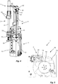
- Fig. 1 shows in a schematic perspective view a device 1 for lifting a sample tube 2 (see Fig. 2 . not shown in Fig. 1 ).
- the device 1 comprises a holder 3, a centering tool 4, a drive system 5 and pillar 6.
- the pillar 6 comprises an upper element 60 and a lower element 62, which are connected fixed in position by means of a coupling element (indicated by broken lines in Fig. 1 ).
- the upper element 60 and the lower element 62 in one embodiment are connected fixed in position by means of a transport plane or a basis of a distribution system functioning as the coupling element.
- the coupling element functions as a mounting component for the device 1.
- the upper element and the lower element are made in one part.
- the centering tool 4 has a pair of centering jaws 40 extending parallel to one another in a longitudinal direction 400, wherein a sample tube placed between the centering jaws 40 is centered with respect to a vertical central axis in the direction perpendicular to the longitudinal direction 400 by moving the jaws 40 to approach each other, in other words by closing the centering jaws 40.
- the centering jaws 40 are provided at opposing surfaces with recesses 41 allowing for a centering of a sample tube also in a direction parallel to the longitudinal direction 400 of the centering jaws 40 upon closing the jaws 40.
- the depicted centering tool 4 further is provided with a linkage system comprising a pair of pivotable tongs 42 arranged in a vertical plane, each pivotable tong 42 being at one end at a pivot joint 43 mounted pivotable about a horizontal axis to the upper element 60 of the pillar 6.
- the centering jaws 40 are rigidly attached to the other ends of the pivotable tongs 42, wherein the centering jaws 40 extend from the pivotable tongs 43 with their longitudinal direction 400 at a 90° angle to the vertical plane.
- the linkage system further comprises a rod 44 extending in the vertical direction and attached to the two tongs 42 at slotted holes 45. The rod 44 is movable in the vertical direction relative to the upper element 60.
- the upper element 60 functions as a guiding element for the rod 44.
- the pivotable tongs 42 are pivoted towards each other and the centering jaws 40 also approach each other moving along a circular path for centering a sample tube arranged between the centering jaws 40.
- the drive system 5 comprises a first slide 50 slidingly mounted to the lower element 62 of the pillar 6 along a guide rail 51 and a belt drive 52 for driving the first slide 50.
- the first slide 50 contacts the rod 44 for a motion transmission via a spring loaded pressure pin 53 as will be explained in more detail below.
- a downward movement of the slide 50 is limited by a stop 55.
- the holder 3 has holding elements 30 for holding a sample tube 2.
- the holding elements 30 are three fingers offset by 120°, wherein a sample tube 2 retained in a sample tube carrier 20 (see Fig. 2 ), which carrier 20 is adapted for receiving one single sample tube 2, is retained between the fingers.
- the holder 3 further comprises a second slide 32 and a column 31 arranged on the second slide 32, wherein the holding elements 30 are provided at the free upper end of the column 31.
- the second slide 32 is also slidingly mounted to the lower element 62 of the pillar 6 along the guide rail 51.
- a sample tube 2 held by the holder 3, more particular by the holding elements 30, is lifted into a position, in which the upper end of the sample tube extends above the centering jaws 40 and a portion of the sample tube 2 is arranged between the centering jaws 40.
- the upwards movement of the second slide 32 is limited by means of a stop 33.
- the second slide 32 is coupled to the first slide 50 for a motion transmission via a spring element 34.
- the spring element 34 more particular its restoration force, is configured such that initially upon moving the first slide 50 from a lower slide position shown in Fig. 1 upwards, the spring element 34 is not or only marginally deformed and the motion of the first slide 50 is transferred to the second slide 32.
- the second slide 32 is hindered from being moved further upwards, and unless the drive system 5 is stopped, the first slide 50 is moved relative to the second slide 32 under deformation of the spring element 34.
- the sample tube 2 is retained in a carrier 20 and positioned for example by means of a conveyor device above the holder 3.
- a support plate or the like (not shown in Fig. 2 ) is provided for supporting the carrier 20 with the sample tube 2 in this position.
- the drive system 5 is operated to move the first slide 50 from the lower slide position shown in Fig. 2 upwards, wherein as shown in Fig. 3 , the motion of the first slide 50 is transferred to the second slide 32 and the sample tube 2 is lifted such that its upper end extends above the centering jaws 40 and a portion of the sample tube 2 is positioned between the centering jaws 40.
- first intermediate slide position When the second slide 32 reaches the stop 33, as shown in Fig. 4 , the motion is no longer transferred to the second slide 32 and the spring element 34 is compressed.
- the position of the first slide 50 when the second slide 32 reaches the limit stop 33 is referred to as first intermediate slide position.
- first slide 50 eventually contacts the rod 44 via the pressure pin 53 and the motion of the first slide 50 is transferred to the rod 44, thereby causing the centering jaws 40 to approach each other.
- the position of the first slide 50 when the pressure pin 53 contacts the rod 44 and the motion transmission to the centering tool 4 is started is referred to as second intermediate slide position.
- the first and the second intermediate position may coincide.
- Sample tubes 2 of different sizes, i.e. different diameters and different lengths can be handled. Therefore, in order to avoid damaging of the sample tubes 2 differing in the diameter when closing the jaws 40, the spring loaded pressure pin 53 is provided. In case a counteracting force at the centering jaws 40 exceeds a threshold, the spring of the pressure pin 53 is compressed and a motion transmission from the first slide 50 to the rod 44 is stopped. Further, the distance between an upper end of the column 31 and, thus, a lower support area of the carrier 20 and the centering jaws 40 is chosen in order to ensure that an upper end of short sample tubes 2 reaches a position in which it is arranged between the centering jaws 40, when the second slide 32 reaches the limit stop 33. As can be seen in Fig. 4 , a sample tube 2 having an average length is contacted by the centering jaws 40 at a middle region upon centering.
- Fig. 5 is a top view of a sample handling device 7 comprising the device 1 shown in Figs. 1 to 4 .
- the sample handling device 7 shown in Fig. 5 comprises a carousel 70, with a rotating disc 72, wherein carriers 20 (not shown in Fig. 5 ) retaining sample tubes 2 or empty carriers 20 can be conveyed to operating stations by a rotation of the disc 72.
- the holder 3 is in the lower position arranged underneath, a supporting plate 73 of the conveyor over which the carriers 20 are slidingly moved.
- the supporting plate 73 is provided with a cutout 74 allowing the holder 3 of the device 1 to contact the carrier 20 when moved upwards.
- the centering tool 4 with the centering jaws 40 is arranged above the supporting plate 73.
- the sample handling device 7 in one embodiment comprises a transport plane, wherein a number of electro-magnetic actuators are stationary arranged below the transport plane, and wherein the electro-magnetic actuators are adapted to move a sample tube carrier 20 together with a sample tube 2 or while empty on top of said transport plane by applying a magnetic force to said sample tube carrier 20.
- a transport plane wherein a number of electro-magnetic actuators are stationary arranged below the transport plane, and wherein the electro-magnetic actuators are adapted to move a sample tube carrier 20 together with a sample tube 2 or while empty on top of said transport plane by applying a magnetic force to said sample tube carrier 20.
Landscapes
- Health & Medical Sciences (AREA)
- Chemical & Material Sciences (AREA)
- Engineering & Computer Science (AREA)
- General Physics & Mathematics (AREA)
- Physics & Mathematics (AREA)
- Life Sciences & Earth Sciences (AREA)
- Analytical Chemistry (AREA)
- Biochemistry (AREA)
- General Health & Medical Sciences (AREA)
- Immunology (AREA)
- Pathology (AREA)
- Robotics (AREA)
- Clinical Laboratory Science (AREA)
- Chemical Kinetics & Catalysis (AREA)
- Mechanical Engineering (AREA)
- Automatic Analysis And Handling Materials Therefor (AREA)
Claims (13)
- Vorrichtung zum Heben eines Probenröhrchens (2), umfassend einen Halter (3) mit Halteelementen (30) zum Halten eines Probenröhrchens (2), ein Zentrierwerkzeug (4) mit einem Paar Zentrierbacken (40), die sich parallel zueinander in Längsrichtung erstrecken, und ein Antriebssystem (5), wobei der Halter (3) in vertikaler Richtung bewegbar zwischen einer unteren Halterposition und einer oberen Halterposition zum Anheben und Absenken eines gehaltenen Probenröhrchens (2) gelagert ist und durch das Antriebssystem (5) mindestens von der unteren Halterposition in die obere Halterposition bewegbar ist,
wobei durch Bewegen des Halters (3) in die obere Position ein gehaltenes Probenröhrchen (2) in eine Position zwischen den Zentrierbacken (40) gehoben wird, und
wobei die Zentrierbacken mittels des Antriebssystems (5) bewegbar sind, so dass sie sich relativ zum angehobenen Probenröhrchen (2) einander nähern, um das angehobene Probenröhrchen (2) in Bezug auf eine vertikale Mittelachse zu zentrieren, und
wobei das Antriebssystem eine erste Gleiteinrichtung (50) umfasst, die in vertikaler Richtung hin und her gehend zwischen einer unteren Gleitposition und einer oberen Gleitposition über eine erste Zwischengleitposition und eine zweite Zwischengleitposition bewegbar gelagert ist, wobei die erste Gleiteinrichtung (50) mit dem Halter (3) zusammenwirkt, um den Halter (3) von der unteren Halterposition in die obere Halterposition zu bewegen, wenn eine Bewegung zwischen der unteren Gleitposition und der ersten Zwischengleitposition erfolgt und mit dem Zentrierwerkzeug (4) zusammenwirkt, um das Zentrierwerkzeug (4) zu betätigen, wenn eine Bewegung zwischen der zweiten Zwischengleitposition und der oberen Gleitposition erfolgt. - Vorrichtung nach Anspruch 1, dadurch gekennzeichnet, dass gegenüberliegende Flächen der Zentrierbacken (40) mit Ausnehmungen (41) versehen sind.
- Vorrichtung nach Anspruch 1 oder 2, dadurch gekennzeichnet, dass die Zentrierbacken (40) starr verbunden sind mit einem Paar verschwenkbarer Zangen (42), insbesondere um einem Winkel von 90° bei einem Paar verschwenkbarer Zangen (42), die in einer vertikalen Ebene angeordnet sind, wobei die verschwenkbaren Zangen (42) um eine horizontale Achse verschwenkbar sind durch Beaufschlagen mit einer Kraft in vertikaler Richtung, so dass die Zentrierbacken (40) veranlasst werden, sich einander anzunähern, um das angehobene Probenröhrchen (2) in Bezug auf die vertikale Mittelachse zu zentrieren.
- Vorrichtung nach einem der Ansprüche 1 bis 3, dadurch gekennzeichnet, dass die erste Zwischengleitposition mit der zweiten Zwischengleitposition übereinstimmt oder unter der zweiten Zwischenposition liegt, so dass bei der Bewegung zwischen der unteren Gleitposition und der übereinstimmenden Zwischenposition oder der ersten Zwischenposition, die erste Gleiteinrichtung (50) nur mit dem Halter (3) zusammenwirkt, um den Halter (3) von der unteren Halterposition in die obere Halterposition zu bewegen, und bei der Bewegung zwischen der übereinstimmenden Zwischenposition oder der zweiten Zwischenposition und der oberen Halterposition, die erste Gleiteinrichtung (50) nur mit dem Zentrierwerkzeug (4) zusammenwirkt, um das Zentrierwerkzeug (4) zu betätigen.
- Vorrichtung nach einem der Ansprüche 1 bis 4, dadurch gekennzeichnet, dass ein federbelasteter Druckstift (53) vorgesehen ist, wobei das Antriebssystem über den Druckstift mit dem Zentrierwerkzeug (4) antreibend gekoppelt ist, und eine Bewegungsübertragung vom Antriebssystem (5) zum Zentrierwerkzeug bei Erreichen einer Grenzkraft unterbrochen wird.
- Vorrichtung nach einem der Ansprüche 1 bis 5, dadurch gekennzeichnet, dass das Antriebssystem (5) einen Riemenantrieb (52) zum Antreiben der ersten Gleiteinrichtung (50) umfasst.
- Vorrichtung nach einem der Ansprüche 1 bis 6, dadurch gekennzeichnet, dass der Halter (3) eine zweite Gleiteinrichtung (32) umfasst, die in vertikaler Richtung bewegbar gelagert ist, wobei insbesondere die erste Gleiteinrichtung (50) und die zweite Gleiteinrichtung (32) entlang einer gemeinsamen Führungsschiene (51) geführt sind.
- Vorrichtung nach Anspruch 7, dadurch gekennzeichnet, dass die erste Gleiteinrichtung (50) und die zweite Gleiteinrichtung (32) mittels eines elastisch verformbaren Elements, insbesondere eines Federelements (34), zur Bewegungsübertragung gekoppelt sind.
- Vorrichtung nach einem der Ansprüche 1 bis 8, dadurch gekennzeichnet, dass ein Anschlag (33) zum Begrenzen der Aufwärtsbewegung des Halters (3) vorgesehen ist.
- Vorrichtung nach einem der Ansprüche 1 bis 9, dadurch gekennzeichnet, dass der Halter (3) eine Säule (31) umfasst, wobei die Halteelemente (30) am oberen Ende der Säule (31) vorgesehen sind.
- Vorrichtung nach einem der Ansprüche 1 bis 10, dadurch gekennzeichnet, dass die Halteelemente (30) ausgebildet sind zum Halten eines Trägers (20), der zum Aufnehmen eines einzelnen Probenröhrchens (2) ausgebildet ist.
- Vorrichtung zur Handhabung von Proben, umfassend mindestens eine Fördereinrichtung (70) zum Befördern eines Probenröhrchens (2) zu einer Arbeitsposition in einer horizontalen Ebene und eine Vorrichtung (1) nach einem der Ansprüche 1 bis 11 zum Heben des Probenröhrchens (2), das an der Arbeitsposition positioniert ist, von der horizontalen Ebene.
- Laborautomatisierungssystem mit einer Anzahl an Voranalyse-, Analyse- und/oder Nachanalysestationen und mit einer Vorrichtung (1) nach einem der Ansprüche 1 bis 11 und/oder mit einer Vorrichtung (7) zur Handhabung von Proben nach Anspruch 12.
Priority Applications (4)
| Application Number | Priority Date | Filing Date | Title |
|---|---|---|---|
| EP16152356.8A EP3196648B1 (de) | 2016-01-22 | 2016-01-22 | Vorrichtung zum heben einer probenröhre |
| JP2017002421A JP6872909B2 (ja) | 2016-01-22 | 2017-01-11 | 試料管を持ち上げるためのデバイス |
| US15/404,322 US10502751B2 (en) | 2016-01-22 | 2017-01-12 | Device for lifting a sample tube |
| CN201710042311.8A CN106996982B (zh) | 2016-01-22 | 2017-01-20 | 用于提升样品管的装置 |
Applications Claiming Priority (1)
| Application Number | Priority Date | Filing Date | Title |
|---|---|---|---|
| EP16152356.8A EP3196648B1 (de) | 2016-01-22 | 2016-01-22 | Vorrichtung zum heben einer probenröhre |
Publications (2)
| Publication Number | Publication Date |
|---|---|
| EP3196648A1 EP3196648A1 (de) | 2017-07-26 |
| EP3196648B1 true EP3196648B1 (de) | 2021-03-31 |
Family
ID=55237509
Family Applications (1)
| Application Number | Title | Priority Date | Filing Date |
|---|---|---|---|
| EP16152356.8A Active EP3196648B1 (de) | 2016-01-22 | 2016-01-22 | Vorrichtung zum heben einer probenröhre |
Country Status (4)
| Country | Link |
|---|---|
| US (1) | US10502751B2 (de) |
| EP (1) | EP3196648B1 (de) |
| JP (1) | JP6872909B2 (de) |
| CN (1) | CN106996982B (de) |
Families Citing this family (21)
| Publication number | Priority date | Publication date | Assignee | Title |
|---|---|---|---|---|
| EP3153438B1 (de) | 2015-10-07 | 2019-11-20 | Roche Diagniostics GmbH | Laborverteilungssystem für fördernde proberöhrchenhalter |
| EP3196655B1 (de) | 2016-01-22 | 2020-11-25 | Roche Diagniostics GmbH | Vorrichtung zur handhabung eines laborprobenbehälterträgers und laborsystem |
| EP3196654B1 (de) | 2016-01-22 | 2023-06-21 | Roche Diagnostics GmbH | Verfahren und vorrichtung zur übertragung von probenröhrchen zwischen einem laborautomatisierungssystem und einem probenarchivierungssystem |
| CN107290562B (zh) * | 2017-08-22 | 2019-09-06 | 重庆博奥新景医学科技有限公司 | 一种用于样品管高通量检测的自动进样系统 |
| CN109765392B (zh) * | 2017-11-09 | 2023-07-25 | 深圳市新产业生物医学工程股份有限公司 | 耗材盒提升机构、自动传输装置及化学发光检测仪 |
| WO2019096963A1 (en) * | 2017-11-17 | 2019-05-23 | Numares Ag | Nmr arrangement and method for transporting a sample tube in an nmr arrangement |
| DE102018111816B4 (de) * | 2018-05-16 | 2021-01-21 | Anton Paar Provetec Gmbh | Vorbereitung einer Destillationsmessung |
| CN108445244B (zh) * | 2018-05-16 | 2024-06-21 | 南京金崎新能源动力研究院有限公司 | 一种试管存取仪 |
| US20200108397A1 (en) * | 2018-10-04 | 2020-04-09 | Hamilton Storage Technologies, Inc. | Tube picking mechanism with universal picking head and cache |
| EP4371667A3 (de) | 2019-05-03 | 2024-07-31 | Gen-Probe Incorporated | Behältertransportsystem für ein analytisches system |
| JP7159472B2 (ja) * | 2019-06-26 | 2022-10-24 | 株式会社日立ハイテク | 検体搬送装置 |
| JP7326113B2 (ja) * | 2019-10-31 | 2023-08-15 | 株式会社日立ハイテク | 検体容器把持装置及び検体搬送装置、接続装置 |
| EP4053566A4 (de) * | 2019-10-31 | 2023-11-08 | Hitachi High-Tech Corporation | Verbindungsvorrichtung und automatisiertes system zur untersuchung von proben |
| CN111999515A (zh) * | 2020-08-26 | 2020-11-27 | 山西医科大学 | 一种药瓶自动加载装置 |
| CN113208661B (zh) * | 2021-05-28 | 2022-04-19 | 湘潭大学 | 一种基于扭转弹簧的棉签持有器 |
| WO2023001733A1 (en) | 2021-07-20 | 2023-01-26 | F. Hoffmann-La Roche Ag | Active centering device for centering a sample holder in a sample handling system |
| CN114246796B (zh) * | 2021-12-21 | 2024-06-14 | 中国科学院自动化研究所 | 新型配液机器人系统 |
| CN115283044B (zh) * | 2022-07-28 | 2023-08-01 | 黄淮学院 | 一种微生物实验用样品归类存放装置及其使用方法 |
| CN115445689B (zh) * | 2022-09-26 | 2023-07-18 | 中科美菱低温科技股份有限公司 | 跟随式冻存管转移模组及方法 |
| CN115979701B (zh) * | 2022-11-08 | 2025-06-10 | 中交上海航道局有限公司 | 用于渣土车的渣土采样装置 |
| CN116619339A (zh) * | 2023-06-26 | 2023-08-22 | 国网湖南省电力有限公司 | 一种带电作业用承力机械臂 |
Citations (1)
| Publication number | Priority date | Publication date | Assignee | Title |
|---|---|---|---|---|
| US6871566B2 (en) * | 2001-09-20 | 2005-03-29 | Aloka Co., Ltd. | Cap opening system and method for opening cap |
Family Cites Families (65)
| Publication number | Priority date | Publication date | Assignee | Title |
|---|---|---|---|---|
| US1892206A (en) | 1932-01-14 | 1932-12-27 | Alvey Mfg Company | Conveyer |
| US2417823A (en) | 1944-10-28 | 1947-03-25 | Wilson & Company Inc | Egg feeding device |
| US2628708A (en) | 1951-01-25 | 1953-02-17 | Ballentine & Sons P | Article raising or lowering conveyer |
| GB797685A (en) | 1955-07-11 | 1958-07-09 | Alfred George Tourell | Improvements in or relating to mechanical handling devices |
| US3036624A (en) | 1959-10-01 | 1962-05-29 | Meyer Geo J Mfg Co | Article feeding apparatus for processing machine |
| US3190466A (en) * | 1963-09-18 | 1965-06-22 | Fruit Equipment Service | Bin stacker and de-stacker mechanism |
| JPS58501145A (ja) * | 1981-07-20 | 1983-07-14 | バックスター インターナショナル インコーポレーテッド | 化学分析器の装入移送組立て体 |
| US4596107A (en) | 1984-10-30 | 1986-06-24 | Pfleger Sr Fred W | Reject mechanism for bottle capping machine |
| JPH0350454Y2 (de) * | 1987-12-24 | 1991-10-28 | ||
| JPH0611448Y2 (ja) * | 1988-03-25 | 1994-03-23 | 照明 伊藤 | 試験管保存管理装置 |
| JPH0355186U (de) * | 1989-09-28 | 1991-05-28 | ||
| US5078057A (en) | 1990-01-05 | 1992-01-07 | Illinois Tool Works Inc. | Binding machine, such as strapping machine |
| JPH03119433U (de) * | 1990-03-15 | 1991-12-10 | ||
| US5297668A (en) | 1993-06-29 | 1994-03-29 | Millard Mfg. Corp. | Conveyor for raising and lowering containers including means for manually removing containers therefrom |
| JPH07234228A (ja) | 1994-02-25 | 1995-09-05 | Hitachi Ltd | 検体搬送システム |
| DE19500148C1 (de) | 1995-01-04 | 1996-08-08 | Bosch Gmbh Robert | Vorrichtung zum Umsetzen von Werkstückträgern |
| DE19512905A1 (de) * | 1995-04-06 | 1996-10-10 | Boehringer Mannheim Gmbh | Vorrichtung zum Herausziehen oder Abdrehen von Verschlüssen von Gefäßen |
| US5567386A (en) | 1995-04-07 | 1996-10-22 | Board Of Regents- Univ. Of Ne | Elevator and speciman carrier for automated conveyor system |
| IT1285963B1 (it) | 1996-06-21 | 1998-06-26 | Gd Spa | Metodo e e dispositivo per il convogliamento con ribaltamento di pacchetti di sigarette |
| US6024204A (en) | 1997-11-14 | 2000-02-15 | Bayer Corporation | Conveyor system for clinical test apparatus |
| US6053303A (en) | 1998-01-21 | 2000-04-25 | Wang; Chao-Yang | Transporting articles |
| JP2000266755A (ja) * | 1999-03-18 | 2000-09-29 | Hitachi Ltd | バーコードラベル貼付け装置 |
| FI116487B (fi) | 1999-11-15 | 2005-11-30 | Thermo Electron Oy | Sovitelma ja menetelmä näyteputkien käsittelemiseksi laboratoriossa |
| JP2004223646A (ja) * | 2003-01-22 | 2004-08-12 | Tosoh Corp | 容器搬送装置 |
| CN2646101Y (zh) | 2003-10-15 | 2004-10-06 | 慧萌高新科技有限公司 | 一种检测电子元件的送料装置 |
| JP3880586B2 (ja) * | 2004-03-26 | 2007-02-14 | 株式会社アイディエス | 試験管栓取外し装置 |
| US7670553B2 (en) | 2005-03-24 | 2010-03-02 | Siemens Healthcare Diagnostics Inc. | Carousel system for automated chemical or biological analyzers employing linear racks |
| KR100707387B1 (ko) * | 2005-10-31 | 2007-04-13 | 주식회사 인아렉스 | 온열치료기용 온열도자의 승하강장치 |
| WO2007087546A2 (en) | 2006-01-23 | 2007-08-02 | Nexus Biosystems, Inc. | Automated system for storing, retreiving and managing samples |
| ATE507477T1 (de) | 2006-10-10 | 2011-05-15 | Inpeco Ip Ltd | Probenbehälter-förderer mit sporneinheiten in automatischen laborsystemen |
| CN101309581A (zh) | 2007-05-17 | 2008-11-19 | 纳瑞精密设备有限公司 | 双分度装置和使用该分度装置传送工件的传送装置 |
| CN201133910Y (zh) * | 2007-12-07 | 2008-10-15 | 深圳迈瑞生物医疗电子股份有限公司 | 一种夹持机构 |
| US7678331B2 (en) | 2007-12-20 | 2010-03-16 | Abbott Laboratories Inc. | Automatic loading of sample tubes for clinical analyzer |
| DE102008030330B4 (de) | 2008-06-30 | 2011-12-08 | Andreas Hettich Gmbh & Co. Kg | Vorrichtung zum Zuführen von Probenbehältern mit einer zu behandelnden Analysenprobe zu einem Behandlungsgerät |
| JP2013501633A (ja) * | 2009-08-07 | 2013-01-17 | シーメンス・ヘルスケア・ダイアグノスティックス・インコーポレーテッド | 試料容器を移送するように適応された方法、システムおよび装置 |
| JP5774994B2 (ja) | 2009-09-30 | 2015-09-09 | 株式会社日立ハイテクノロジーズ | 検体検査自動化システム |
| DE102010028769A1 (de) | 2010-05-07 | 2011-11-10 | Pvt Probenverteiltechnik Gmbh | System zum Transportieren von Behältern zwischen unterschiedlichen Stationen und Behälterträger |
| BR112012030035A2 (pt) | 2010-05-25 | 2016-08-02 | Otsuka Pharma Co Ltd | sistema de enchimento asséptico |
| DE202011111050U1 (de) | 2010-10-29 | 2018-11-20 | Thermo Fisher Scientific Oy | Automatisiertes System zur Probenaufbereitung und -analyse |
| US9267957B2 (en) | 2010-11-23 | 2016-02-23 | Roche Diagnostics Operations, Inc. | Junction and system for transporting sample racks |
| EP2707726B1 (de) | 2011-05-13 | 2018-07-18 | Beckman Coulter, Inc. | System und verfahren mit einem transportelement für laborprodukte |
| EP2589967A1 (de) | 2011-11-04 | 2013-05-08 | Roche Diagnostics GmbH | Laborprobenverteilungssystem und entsprechendes Betriebsverfahren |
| EP2589968A1 (de) * | 2011-11-04 | 2013-05-08 | Roche Diagnostics GmbH | Laborprobenverteilungssystem, Laborsystem und Betriebsverfahren |
| BR112014010955A2 (pt) | 2011-11-07 | 2017-06-06 | Beckman Coulter Inc | sistema e método para processar amostras |
| BR112014011044A2 (pt) | 2011-11-07 | 2017-04-25 | Beckman Coulter Inc | amortecimento magnético para sistema de transporte de espécime |
| DE102011055899B4 (de) * | 2011-11-30 | 2013-11-21 | Andreas Hettich Gmbh & Co. Kg | Verfahren und eine Vorrichtung zum Handhaben von Probenbehältern |
| CN102602697A (zh) | 2011-12-12 | 2012-07-25 | 苏州工业园区高登威科技有限公司 | 带有产品传送机构的加工台 |
| JP5514850B2 (ja) | 2012-03-08 | 2014-06-04 | あおい精機株式会社 | 搬送装置及び搬送方法 |
| WO2014002953A1 (ja) * | 2012-06-25 | 2014-01-03 | 協和メデックス株式会社 | 容器把持装置 |
| ITMI20121218A1 (it) | 2012-07-12 | 2014-01-13 | Inpeco Ip Ltd | Stazione di accantonamento provvisorio di dispositivi di trasporto di contenitori di prodotti biologici |
| WO2014025817A1 (en) * | 2012-08-06 | 2014-02-13 | Beckman Coulter, Inc. | Sensing specimen gripper |
| WO2014050437A1 (ja) | 2012-09-26 | 2014-04-03 | 株式会社日立ハイテクノロジーズ | サンプル搬送装置および検体検査自動化システム |
| DE102013100627A1 (de) | 2013-01-22 | 2014-07-24 | Krones Aktiengesellschaft | Verfahren zum betreiben einer behälterbehandlungsanlage und behälterbehandlungsanlage |
| JP6101091B2 (ja) * | 2013-01-29 | 2017-03-22 | 株式会社日立ハイテクノロジーズ | 検体容器移動システムおよび検体容器移動方法 |
| JP5547320B1 (ja) | 2013-03-19 | 2014-07-09 | 第一施設工業株式会社 | 搬送装置 |
| EP2804002B1 (de) | 2013-05-15 | 2019-09-25 | F. Hoffmann-La Roche AG | Automatisiertes Laborsystem mit gemeinsamem Probensortierungmodul |
| ITMI20131763A1 (it) | 2013-10-23 | 2015-04-24 | Inpeco Holding Ltd | Apparato per il trasferimento di campioni di materiale biologico tra impianti di automazione di laboratorio posti ad altezze diverse. |
| EP2887071B1 (de) | 2013-12-19 | 2018-12-05 | F. Hoffmann-La Roche AG | Lagerung und Bereitstellung von Gefäßhaltern |
| JP6087274B2 (ja) | 2013-12-27 | 2017-03-01 | シスメックス株式会社 | 検体処理装置 |
| WO2015111526A1 (ja) * | 2014-01-27 | 2015-07-30 | 株式会社 日立ハイテクノロジーズ | 自動分析装置 |
| CN204613223U (zh) | 2015-05-04 | 2015-09-02 | 武汉中科波谱技术有限公司 | 一种自动进样器 |
| EP3153438B1 (de) | 2015-10-07 | 2019-11-20 | Roche Diagniostics GmbH | Laborverteilungssystem für fördernde proberöhrchenhalter |
| EP3196654B1 (de) | 2016-01-22 | 2023-06-21 | Roche Diagnostics GmbH | Verfahren und vorrichtung zur übertragung von probenröhrchen zwischen einem laborautomatisierungssystem und einem probenarchivierungssystem |
| EP3196655B1 (de) | 2016-01-22 | 2020-11-25 | Roche Diagniostics GmbH | Vorrichtung zur handhabung eines laborprobenbehälterträgers und laborsystem |
| EP3255436B1 (de) | 2016-06-06 | 2022-09-21 | F. Hoffmann-La Roche AG | Zuführung verbrauchbarer artikel an einen automatisierten probenanalysator |
-
2016
- 2016-01-22 EP EP16152356.8A patent/EP3196648B1/de active Active
-
2017
- 2017-01-11 JP JP2017002421A patent/JP6872909B2/ja active Active
- 2017-01-12 US US15/404,322 patent/US10502751B2/en active Active
- 2017-01-20 CN CN201710042311.8A patent/CN106996982B/zh active Active
Patent Citations (1)
| Publication number | Priority date | Publication date | Assignee | Title |
|---|---|---|---|---|
| US6871566B2 (en) * | 2001-09-20 | 2005-03-29 | Aloka Co., Ltd. | Cap opening system and method for opening cap |
Also Published As
| Publication number | Publication date |
|---|---|
| US10502751B2 (en) | 2019-12-10 |
| JP6872909B2 (ja) | 2021-05-19 |
| US20170212139A1 (en) | 2017-07-27 |
| CN106996982B (zh) | 2019-11-05 |
| JP2017129576A (ja) | 2017-07-27 |
| EP3196648A1 (de) | 2017-07-26 |
| CN106996982A (zh) | 2017-08-01 |
Similar Documents
| Publication | Publication Date | Title |
|---|---|---|
| EP3196648B1 (de) | Vorrichtung zum heben einer probenröhre | |
| US5819508A (en) | Device for removing or twisting off caps from vessels | |
| US6592324B2 (en) | Gripper mechanism | |
| EP2613156B1 (de) | Probenübertragungsmechanismus | |
| EP1546737B1 (de) | Zweiachsenroboter für den probentransfer | |
| CN102841211B (zh) | 用于为样品管去盖和重新加盖的装置 | |
| EP1353183B1 (de) | Vorrichtung zur Probenvorbehandlung | |
| EP1355766B1 (de) | Verfahren und vorrichtung zum aufnehmen und abstellen von behältern | |
| CN101558312B (zh) | 具有自动定位补偿的容器传输装置 | |
| EP3484679B1 (de) | Verfahren, systeme und vorrichtung zur dynamischen aufnahme und platzierung einer auswahlfolge auf der grundlage von probengestellbildgebungsdaten | |
| US20130239527A1 (en) | Method and a device for handling sample containers | |
| US11215625B2 (en) | Method for receiving a sample vessel from a sample carrier, and device designed to carry out the method | |
| CN104237548B (zh) | 用于处理样品管的装置和方法以及实验系统 | |
| JPWO2007132526A1 (ja) | シャトル型搬送装置、マイクロプレート供給回収装置、マイクロプレート用ピックアップ装置、マイクロプレート用カセット、及びマイクロプレート用収納棚 | |
| JP2011522270A (ja) | 生体サンプルホルダの把持に適したクランプ、生体サンプルホルダおよび適したクランプから成るアセンブリ、ならびに処理および/または解析のための装置 | |
| JP5693655B2 (ja) | 自動検体処理装置 | |
| EP3029468B1 (de) | Vorrichtung zum Neupositionieren von Röhrchen in einem Röhrchenständer | |
| US20190101552A1 (en) | Conveying device | |
| EP2235545B1 (de) | Vorrichtung zum verschliessen von behältern für biologisches material | |
| CN107607732B (zh) | 自动分析器 | |
| US11945664B2 (en) | Pneumatic dispatch station having a tool changer | |
| CN112292339B (zh) | 抓取容器的装置 | |
| WO2010054479A1 (en) | Universal container carrier | |
| JP7084760B2 (ja) | 診断試験所内移送コンパートメント用センタリングユニット | |
| CN219669397U (zh) | 用于制片工作站的采样瓶自动对接上料装置 |
Legal Events
| Date | Code | Title | Description |
|---|---|---|---|
| PUAI | Public reference made under article 153(3) epc to a published international application that has entered the european phase |
Free format text: ORIGINAL CODE: 0009012 |
|
| STAA | Information on the status of an ep patent application or granted ep patent |
Free format text: STATUS: THE APPLICATION HAS BEEN PUBLISHED |
|
| AK | Designated contracting states |
Kind code of ref document: A1 Designated state(s): AL AT BE BG CH CY CZ DE DK EE ES FI FR GB GR HR HU IE IS IT LI LT LU LV MC MK MT NL NO PL PT RO RS SE SI SK SM TR |
|
| AX | Request for extension of the european patent |
Extension state: BA ME |
|
| STAA | Information on the status of an ep patent application or granted ep patent |
Free format text: STATUS: REQUEST FOR EXAMINATION WAS MADE |
|
| 17P | Request for examination filed |
Effective date: 20180124 |
|
| RBV | Designated contracting states (corrected) |
Designated state(s): AL AT BE BG CH CY CZ DE DK EE ES FI FR GB GR HR HU IE IS IT LI LT LU LV MC MK MT NL NO PL PT RO RS SE SI SK SM TR |
|
| STAA | Information on the status of an ep patent application or granted ep patent |
Free format text: STATUS: EXAMINATION IS IN PROGRESS |
|
| 17Q | First examination report despatched |
Effective date: 20200218 |
|
| RIC1 | Information provided on ipc code assigned before grant |
Ipc: B01L 9/00 20060101ALI20200820BHEP Ipc: G01N 35/04 20060101ALN20200820BHEP Ipc: G01N 35/00 20060101AFI20200820BHEP |
|
| GRAP | Despatch of communication of intention to grant a patent |
Free format text: ORIGINAL CODE: EPIDOSNIGR1 |
|
| STAA | Information on the status of an ep patent application or granted ep patent |
Free format text: STATUS: GRANT OF PATENT IS INTENDED |
|
| INTG | Intention to grant announced |
Effective date: 20201102 |
|
| GRAS | Grant fee paid |
Free format text: ORIGINAL CODE: EPIDOSNIGR3 |
|
| GRAA | (expected) grant |
Free format text: ORIGINAL CODE: 0009210 |
|
| STAA | Information on the status of an ep patent application or granted ep patent |
Free format text: STATUS: THE PATENT HAS BEEN GRANTED |
|
| AK | Designated contracting states |
Kind code of ref document: B1 Designated state(s): AL AT BE BG CH CY CZ DE DK EE ES FI FR GB GR HR HU IE IS IT LI LT LU LV MC MK MT NL NO PL PT RO RS SE SI SK SM TR |
|
| REG | Reference to a national code |
Ref country code: GB Ref legal event code: FG4D Ref country code: CH Ref legal event code: EP |
|
| REG | Reference to a national code |
Ref country code: DE Ref legal event code: R096 Ref document number: 602016055087 Country of ref document: DE Ref country code: AT Ref legal event code: REF Ref document number: 1377530 Country of ref document: AT Kind code of ref document: T Effective date: 20210415 |
|
| REG | Reference to a national code |
Ref country code: IE Ref legal event code: FG4D |
|
| REG | Reference to a national code |
Ref country code: LT Ref legal event code: MG9D |
|
| PG25 | Lapsed in a contracting state [announced via postgrant information from national office to epo] |
Ref country code: FI Free format text: LAPSE BECAUSE OF FAILURE TO SUBMIT A TRANSLATION OF THE DESCRIPTION OR TO PAY THE FEE WITHIN THE PRESCRIBED TIME-LIMIT Effective date: 20210331 Ref country code: HR Free format text: LAPSE BECAUSE OF FAILURE TO SUBMIT A TRANSLATION OF THE DESCRIPTION OR TO PAY THE FEE WITHIN THE PRESCRIBED TIME-LIMIT Effective date: 20210331 Ref country code: BG Free format text: LAPSE BECAUSE OF FAILURE TO SUBMIT A TRANSLATION OF THE DESCRIPTION OR TO PAY THE FEE WITHIN THE PRESCRIBED TIME-LIMIT Effective date: 20210630 Ref country code: NO Free format text: LAPSE BECAUSE OF FAILURE TO SUBMIT A TRANSLATION OF THE DESCRIPTION OR TO PAY THE FEE WITHIN THE PRESCRIBED TIME-LIMIT Effective date: 20210630 |
|
| PG25 | Lapsed in a contracting state [announced via postgrant information from national office to epo] |
Ref country code: RS Free format text: LAPSE BECAUSE OF FAILURE TO SUBMIT A TRANSLATION OF THE DESCRIPTION OR TO PAY THE FEE WITHIN THE PRESCRIBED TIME-LIMIT Effective date: 20210331 Ref country code: LV Free format text: LAPSE BECAUSE OF FAILURE TO SUBMIT A TRANSLATION OF THE DESCRIPTION OR TO PAY THE FEE WITHIN THE PRESCRIBED TIME-LIMIT Effective date: 20210331 Ref country code: SE Free format text: LAPSE BECAUSE OF FAILURE TO SUBMIT A TRANSLATION OF THE DESCRIPTION OR TO PAY THE FEE WITHIN THE PRESCRIBED TIME-LIMIT Effective date: 20210331 |
|
| REG | Reference to a national code |
Ref country code: NL Ref legal event code: MP Effective date: 20210331 |
|
| REG | Reference to a national code |
Ref country code: AT Ref legal event code: MK05 Ref document number: 1377530 Country of ref document: AT Kind code of ref document: T Effective date: 20210331 |
|
| PG25 | Lapsed in a contracting state [announced via postgrant information from national office to epo] |
Ref country code: EE Free format text: LAPSE BECAUSE OF FAILURE TO SUBMIT A TRANSLATION OF THE DESCRIPTION OR TO PAY THE FEE WITHIN THE PRESCRIBED TIME-LIMIT Effective date: 20210331 Ref country code: CZ Free format text: LAPSE BECAUSE OF FAILURE TO SUBMIT A TRANSLATION OF THE DESCRIPTION OR TO PAY THE FEE WITHIN THE PRESCRIBED TIME-LIMIT Effective date: 20210331 Ref country code: LT Free format text: LAPSE BECAUSE OF FAILURE TO SUBMIT A TRANSLATION OF THE DESCRIPTION OR TO PAY THE FEE WITHIN THE PRESCRIBED TIME-LIMIT Effective date: 20210331 Ref country code: NL Free format text: LAPSE BECAUSE OF FAILURE TO SUBMIT A TRANSLATION OF THE DESCRIPTION OR TO PAY THE FEE WITHIN THE PRESCRIBED TIME-LIMIT Effective date: 20210331 Ref country code: AT Free format text: LAPSE BECAUSE OF FAILURE TO SUBMIT A TRANSLATION OF THE DESCRIPTION OR TO PAY THE FEE WITHIN THE PRESCRIBED TIME-LIMIT Effective date: 20210331 Ref country code: SM Free format text: LAPSE BECAUSE OF FAILURE TO SUBMIT A TRANSLATION OF THE DESCRIPTION OR TO PAY THE FEE WITHIN THE PRESCRIBED TIME-LIMIT Effective date: 20210331 |
|
| PG25 | Lapsed in a contracting state [announced via postgrant information from national office to epo] |
Ref country code: IS Free format text: LAPSE BECAUSE OF FAILURE TO SUBMIT A TRANSLATION OF THE DESCRIPTION OR TO PAY THE FEE WITHIN THE PRESCRIBED TIME-LIMIT Effective date: 20210731 Ref country code: PL Free format text: LAPSE BECAUSE OF FAILURE TO SUBMIT A TRANSLATION OF THE DESCRIPTION OR TO PAY THE FEE WITHIN THE PRESCRIBED TIME-LIMIT Effective date: 20210331 Ref country code: PT Free format text: LAPSE BECAUSE OF FAILURE TO SUBMIT A TRANSLATION OF THE DESCRIPTION OR TO PAY THE FEE WITHIN THE PRESCRIBED TIME-LIMIT Effective date: 20210802 Ref country code: SK Free format text: LAPSE BECAUSE OF FAILURE TO SUBMIT A TRANSLATION OF THE DESCRIPTION OR TO PAY THE FEE WITHIN THE PRESCRIBED TIME-LIMIT Effective date: 20210331 Ref country code: RO Free format text: LAPSE BECAUSE OF FAILURE TO SUBMIT A TRANSLATION OF THE DESCRIPTION OR TO PAY THE FEE WITHIN THE PRESCRIBED TIME-LIMIT Effective date: 20210331 |
|
| REG | Reference to a national code |
Ref country code: DE Ref legal event code: R097 Ref document number: 602016055087 Country of ref document: DE |
|
| PG25 | Lapsed in a contracting state [announced via postgrant information from national office to epo] |
Ref country code: ES Free format text: LAPSE BECAUSE OF FAILURE TO SUBMIT A TRANSLATION OF THE DESCRIPTION OR TO PAY THE FEE WITHIN THE PRESCRIBED TIME-LIMIT Effective date: 20210331 Ref country code: AL Free format text: LAPSE BECAUSE OF FAILURE TO SUBMIT A TRANSLATION OF THE DESCRIPTION OR TO PAY THE FEE WITHIN THE PRESCRIBED TIME-LIMIT Effective date: 20210331 Ref country code: DK Free format text: LAPSE BECAUSE OF FAILURE TO SUBMIT A TRANSLATION OF THE DESCRIPTION OR TO PAY THE FEE WITHIN THE PRESCRIBED TIME-LIMIT Effective date: 20210331 |
|
| PLBE | No opposition filed within time limit |
Free format text: ORIGINAL CODE: 0009261 |
|
| STAA | Information on the status of an ep patent application or granted ep patent |
Free format text: STATUS: NO OPPOSITION FILED WITHIN TIME LIMIT |
|
| 26N | No opposition filed |
Effective date: 20220104 |
|
| PG25 | Lapsed in a contracting state [announced via postgrant information from national office to epo] |
Ref country code: IS Free format text: LAPSE BECAUSE OF FAILURE TO SUBMIT A TRANSLATION OF THE DESCRIPTION OR TO PAY THE FEE WITHIN THE PRESCRIBED TIME-LIMIT Effective date: 20210731 |
|
| PG25 | Lapsed in a contracting state [announced via postgrant information from national office to epo] |
Ref country code: MC Free format text: LAPSE BECAUSE OF FAILURE TO SUBMIT A TRANSLATION OF THE DESCRIPTION OR TO PAY THE FEE WITHIN THE PRESCRIBED TIME-LIMIT Effective date: 20210331 |
|
| REG | Reference to a national code |
Ref country code: BE Ref legal event code: MM Effective date: 20220131 |
|
| PG25 | Lapsed in a contracting state [announced via postgrant information from national office to epo] |
Ref country code: LU Free format text: LAPSE BECAUSE OF NON-PAYMENT OF DUE FEES Effective date: 20220122 |
|
| PG25 | Lapsed in a contracting state [announced via postgrant information from national office to epo] |
Ref country code: BE Free format text: LAPSE BECAUSE OF NON-PAYMENT OF DUE FEES Effective date: 20220131 |
|
| PG25 | Lapsed in a contracting state [announced via postgrant information from national office to epo] |
Ref country code: IE Free format text: LAPSE BECAUSE OF NON-PAYMENT OF DUE FEES Effective date: 20220122 |
|
| PG25 | Lapsed in a contracting state [announced via postgrant information from national office to epo] |
Ref country code: HU Free format text: LAPSE BECAUSE OF FAILURE TO SUBMIT A TRANSLATION OF THE DESCRIPTION OR TO PAY THE FEE WITHIN THE PRESCRIBED TIME-LIMIT; INVALID AB INITIO Effective date: 20160122 |
|
| PG25 | Lapsed in a contracting state [announced via postgrant information from national office to epo] |
Ref country code: MK Free format text: LAPSE BECAUSE OF FAILURE TO SUBMIT A TRANSLATION OF THE DESCRIPTION OR TO PAY THE FEE WITHIN THE PRESCRIBED TIME-LIMIT Effective date: 20210331 Ref country code: CY Free format text: LAPSE BECAUSE OF FAILURE TO SUBMIT A TRANSLATION OF THE DESCRIPTION OR TO PAY THE FEE WITHIN THE PRESCRIBED TIME-LIMIT Effective date: 20210331 |
|
| PG25 | Lapsed in a contracting state [announced via postgrant information from national office to epo] |
Ref country code: MT Free format text: LAPSE BECAUSE OF FAILURE TO SUBMIT A TRANSLATION OF THE DESCRIPTION OR TO PAY THE FEE WITHIN THE PRESCRIBED TIME-LIMIT Effective date: 20210331 |
|
| PG25 | Lapsed in a contracting state [announced via postgrant information from national office to epo] |
Ref country code: GR Free format text: LAPSE BECAUSE OF NON-PAYMENT OF DUE FEES Effective date: 20210331 |
|
| PG25 | Lapsed in a contracting state [announced via postgrant information from national office to epo] |
Ref country code: GR Free format text: LAPSE BECAUSE OF NON-PAYMENT OF DUE FEES Effective date: 20210331 |
|
| PGFP | Annual fee paid to national office [announced via postgrant information from national office to epo] |
Ref country code: CH Payment date: 20250201 Year of fee payment: 10 |
|
| PG25 | Lapsed in a contracting state [announced via postgrant information from national office to epo] |
Ref country code: TR Free format text: LAPSE BECAUSE OF FAILURE TO SUBMIT A TRANSLATION OF THE DESCRIPTION OR TO PAY THE FEE WITHIN THE PRESCRIBED TIME-LIMIT Effective date: 20210331 |
|
| PGFP | Annual fee paid to national office [announced via postgrant information from national office to epo] |
Ref country code: GB Payment date: 20251220 Year of fee payment: 11 |
|
| PGFP | Annual fee paid to national office [announced via postgrant information from national office to epo] |
Ref country code: FR Payment date: 20251217 Year of fee payment: 11 |
|
| REG | Reference to a national code |
Ref country code: CH Ref legal event code: U11 Free format text: ST27 STATUS EVENT CODE: U-0-0-U10-U11 (AS PROVIDED BY THE NATIONAL OFFICE) Effective date: 20260201 |
|
| PGFP | Annual fee paid to national office [announced via postgrant information from national office to epo] |
Ref country code: DE Payment date: 20251217 Year of fee payment: 11 |
|
| PGFP | Annual fee paid to national office [announced via postgrant information from national office to epo] |
Ref country code: IT Payment date: 20260107 Year of fee payment: 11 |