EP3196863B1 - System und verfahren zur flugzeugandockführung und zur flugzeugtypidentifizierung - Google Patents
System und verfahren zur flugzeugandockführung und zur flugzeugtypidentifizierung Download PDFInfo
- Publication number
- EP3196863B1 EP3196863B1 EP15827975.2A EP15827975A EP3196863B1 EP 3196863 B1 EP3196863 B1 EP 3196863B1 EP 15827975 A EP15827975 A EP 15827975A EP 3196863 B1 EP3196863 B1 EP 3196863B1
- Authority
- EP
- European Patent Office
- Prior art keywords
- aircraft
- front wheel
- image
- point
- threshold
- Prior art date
- Legal status (The legal status is an assumption and is not a legal conclusion. Google has not performed a legal analysis and makes no representation as to the accuracy of the status listed.)
- Active
Links
Images


Classifications
-
- G—PHYSICS
- G06—COMPUTING OR CALCULATING; COUNTING
- G06V—IMAGE OR VIDEO RECOGNITION OR UNDERSTANDING
- G06V20/00—Scenes; Scene-specific elements
- G06V20/50—Context or environment of the image
- G06V20/56—Context or environment of the image exterior to a vehicle by using sensors mounted on the vehicle
-
- B—PERFORMING OPERATIONS; TRANSPORTING
- B64—AIRCRAFT; AVIATION; COSMONAUTICS
- B64F—GROUND OR AIRCRAFT-CARRIER-DECK INSTALLATIONS SPECIALLY ADAPTED FOR USE IN CONNECTION WITH AIRCRAFT; DESIGNING, MANUFACTURING, ASSEMBLING, CLEANING, MAINTAINING OR REPAIRING AIRCRAFT, NOT OTHERWISE PROVIDED FOR; HANDLING, TRANSPORTING, TESTING OR INSPECTING AIRCRAFT COMPONENTS, NOT OTHERWISE PROVIDED FOR
- B64F1/00—Ground or aircraft-carrier-deck installations
- B64F1/002—Taxiing aids
-
- G—PHYSICS
- G01—MEASURING; TESTING
- G01S—RADIO DIRECTION-FINDING; RADIO NAVIGATION; DETERMINING DISTANCE OR VELOCITY BY USE OF RADIO WAVES; LOCATING OR PRESENCE-DETECTING BY USE OF THE REFLECTION OR RERADIATION OF RADIO WAVES; ANALOGOUS ARRANGEMENTS USING OTHER WAVES
- G01S17/00—Systems using the reflection or reradiation of electromagnetic waves other than radio waves, e.g. lidar systems
- G01S17/02—Systems using the reflection of electromagnetic waves other than radio waves
- G01S17/06—Systems determining position data of a target
-
- G—PHYSICS
- G01—MEASURING; TESTING
- G01S—RADIO DIRECTION-FINDING; RADIO NAVIGATION; DETERMINING DISTANCE OR VELOCITY BY USE OF RADIO WAVES; LOCATING OR PRESENCE-DETECTING BY USE OF THE REFLECTION OR RERADIATION OF RADIO WAVES; ANALOGOUS ARRANGEMENTS USING OTHER WAVES
- G01S17/00—Systems using the reflection or reradiation of electromagnetic waves other than radio waves, e.g. lidar systems
- G01S17/88—Lidar systems specially adapted for specific applications
-
- G—PHYSICS
- G06—COMPUTING OR CALCULATING; COUNTING
- G06V—IMAGE OR VIDEO RECOGNITION OR UNDERSTANDING
- G06V20/00—Scenes; Scene-specific elements
- G06V20/50—Context or environment of the image
- G06V20/56—Context or environment of the image exterior to a vehicle by using sensors mounted on the vehicle
- G06V20/58—Recognition of moving objects or obstacles, e.g. vehicles or pedestrians; Recognition of traffic objects, e.g. traffic signs, traffic lights or roads
-
- G—PHYSICS
- G06—COMPUTING OR CALCULATING; COUNTING
- G06V—IMAGE OR VIDEO RECOGNITION OR UNDERSTANDING
- G06V20/00—Scenes; Scene-specific elements
- G06V20/50—Context or environment of the image
- G06V20/56—Context or environment of the image exterior to a vehicle by using sensors mounted on the vehicle
- G06V20/588—Recognition of the road, e.g. of lane markings; Recognition of the vehicle driving pattern in relation to the road
-
- G—PHYSICS
- G08—SIGNALLING
- G08G—TRAFFIC CONTROL SYSTEMS
- G08G5/00—Traffic control systems for aircraft
- G08G5/50—Navigation or guidance aids
- G08G5/51—Navigation or guidance aids for control when on the ground, e.g. taxiing or rolling
-
- B—PERFORMING OPERATIONS; TRANSPORTING
- B64—AIRCRAFT; AVIATION; COSMONAUTICS
- B64F—GROUND OR AIRCRAFT-CARRIER-DECK INSTALLATIONS SPECIALLY ADAPTED FOR USE IN CONNECTION WITH AIRCRAFT; DESIGNING, MANUFACTURING, ASSEMBLING, CLEANING, MAINTAINING OR REPAIRING AIRCRAFT, NOT OTHERWISE PROVIDED FOR; HANDLING, TRANSPORTING, TESTING OR INSPECTING AIRCRAFT COMPONENTS, NOT OTHERWISE PROVIDED FOR
- B64F1/00—Ground or aircraft-carrier-deck installations
-
- G—PHYSICS
- G06—COMPUTING OR CALCULATING; COUNTING
- G06V—IMAGE OR VIDEO RECOGNITION OR UNDERSTANDING
- G06V10/00—Arrangements for image or video recognition or understanding
- G06V10/10—Image acquisition
-
- G—PHYSICS
- G06—COMPUTING OR CALCULATING; COUNTING
- G06V—IMAGE OR VIDEO RECOGNITION OR UNDERSTANDING
- G06V10/00—Arrangements for image or video recognition or understanding
- G06V10/20—Image preprocessing
-
- H—ELECTRICITY
- H04—ELECTRIC COMMUNICATION TECHNIQUE
- H04N—PICTORIAL COMMUNICATION, e.g. TELEVISION
- H04N7/00—Television systems
Definitions
- the present disclosure generally relates to a docking guidance system, and more particularly, to an aircraft docking guidance and aircraft type identification system and method.
- Aircraft docking guidance refers to a process of guiding an arriving aircraft from an end of a taxiway to a parking position at an apron and guiding the aircraft to stop at a designated exact position.
- the aim of the docking guidance is to ensure safe and accurate docking of the arriving aircraft, to facilitate accurate cooperation of the aircraft with various ground interfaces (ground crews), and to make the passenger boarding bridge (PBB) accurately connected to the aircraft door and thereby improve the efficiency and safety of the airport.
- ground crews ground crews
- PBB passenger boarding bridge
- Automated aircraft docking guidance systems may be divided into the following categories depending on the types of the employed sensors: (1) buried loop coils category; (2) laser scanning and ranging category; (3) visual perception category.
- the automated guidance systems of the laser scanning and ranging category and the visual perception category can obtain visual information about an aircraft being docked, the two categories of automated aircraft docking guidance systems can be called as visual docking guidance systems.
- the automated guidance systems using buried loop coils detect whether there is a metal object passing or stopping to determine the position of an arriving aircraft.
- the systems using the buried loop coils have advantages such as fast response speed, low costs and no requirements on weather and illumination, but these systems are not accurate and have low anti-interference capability. Also, leads and electronic elements buried in the ground can be broken easily and have low reliability, and such elements have low measurement accuracy, cannot identify aircraft types, and are less debuggable and maintainable.
- the automated docking guidance systems of the laser scanning and ranging category determine information such as positions, speeds and types of aircrafts by laser scanning and ranging, are less influenced by environment illumination and weather, have high accuracy and are debuggable and maintainable.
- the automated docking guidance systems of the visual perception category obtain image information about the procedure of aircraft docking by optical imaging, and determine information such as positions, speeds and types of the aircrafts being docked based on intelligent information process technologies. These systems have advantages such as simple structure, low costs, high intelligent level, being debuggable and maintainable, but have shortcomings of high requirements on weather and illumination and poor adaptability.
- visual aircraft docking guidance technologies(systems) can obtain docking information about aircrafts being docked accurately and fast, and have been widely applied in docking guidance systems of many airports.
- VDGS Visual Docking Guidance System
- VDOCKS Video Docking System
- the technical problem to be solved by the present disclosure is to realize aircraft docking guidance, and to accurately determine deviation of a front wheel of an aircraft while effectively guiding the aircraft to be docked.
- an embodiment of the present invention provides an aircraft docking guidance and type identification method, as defined with the claims, performed by an aircraft docking guidance and type identification system which includes a machine vision subsystem, a laser scanning subsystem and a fusion module.
- Fig. 1 is a block diagram illustratively showing a structure of an aircraft docking guidance and type identification system according to an embodiment of the present invention.
- the aircraft docking guidance and type identification system mainly includes a machine vision subsystem 1000, a laser scanning subsystem 2000, a vision information and laser information fusion unit 3000 and a display device 4000.
- the machine vision subsystem 1000, the laser scanning subsystem 2000 and the display device 4000 are connected to the vision information and laser information fusion unit 3000.
- the machine vision subsystem 1000 and the laser scanning subsystem 2000 correspond to the same aircraft dock, and obtain docking information of aircrafts, and send the obtained information to the vision information and laser information fusion unit 3000 which fuses the information into one set of information and sends the set of information to the display device 4000 for display.
- FIGs. 2A and 2B are block diagrams illustratively showing a structure of a machine vision subsystem according to an embodiment of the present disclosure.
- the machine vision subsystem 1000 mainly includes a camera device 1001 and a central process device 1002.
- the camera device 1001 is connected to the central process device 1002 which sends the processed information to the information fusion module 3000.
- the camera device 1001 is disposed behind a stopping line 42 of an aircraft docking apron 40, preferably, directly facing a guidance line 41.
- the camera device 1001 may be mounted at a height above the body of an aircraft 5, for example, 5 to 8 meters above the aircraft body.
- the camera device 1001 sends captured images to the central process device 1002.
- the central process device 1002 may be a computing device which is capable of receiving, processing and storing data, generating image data to be displayed, and sending data.
- the central process device 1002 may include a plurality of functional modules which are configured to configure the aircraft docking scene, preprocess videos and images, capture aircrafts, track aircrafts, locate aircrafts, identify aircraft types and verify identities, and all of the functional modules can be implemented as software installed in the central process device 1002.
- the display device 4000 may be a large information display screen which is mounted at an airport for pilots to view, for example. Further, airport crew may be provided with hand-held display devices to view conditions of aircrafts.
- Fig. 3 is a flow chart illustratively showing an aircraft docking guidance and type identification method according to an embodiment of the present disclosure.
- the machine vision-based aircraft docking guidance and type identification method provided by the present disclosure may include the following steps.
- step S1 aircraft docking scene is set.
- the aircraft docking scene setting refers to dividing a monitoring scene into different information process functional areas, and determining specific positions and states of some important reference objects in the scene.
- the aircraft docking scene setting is the basis for effectively processing aircraft docking information.
- An aircraft may go through a long distance from entering into an apron to finally stopping, and thus the procedure of aircraft docking guidance can be divided into a plurality of phases, and different contents need to be monitored during different phases. That is to say, the scene for aircraft docking needs to be set in advance.
- step S1 the monitoring scene of the aircraft docking apron 40 is divided into different functional areas for different information process to reduce the process range of pictures and thereby increase process efficiency.
- the guidance line and the stopping line are two of the most important markings in the aircraft docking scene.
- Effective identifying of the positions of the guidance line and the stopping line is an important basis and an essential part for ensuring successful aircraft docking, and is also a key factor for distinguishing the functional areas.
- Individual functional areas are marked in the present disclosure to perform corresponding guidance information process tasks at these functional areas. Further, relevant ground device areas are marked to avoid accidents during aircraft docking.
- defining of the monitoring scene of the aircraft docking apron 40 can be performed first.
- a ruler on which alternating black and white stripes are arranged is laid immediately adjacent to the guidance line 41, the interval between the black stripes and the interval between the white stripes may be the same, and the maximum interval may be 1m, for example.
- finer rulers with an interval of 0.5 meter, or 0.25 meter may be used.
- the total length of the ruler may be not beyond the range within which distance and position calculation with respect to aircrafts are performed, for example, the length is usually 50 meters.
- the monitoring scene can be reconstructed.
- images captured by the camera device 1001 with respect to the aircraft docking apron 40 can be displayed, and relevant areas can be marked by drawing lines, selection boxes or points manually, and records can be stored.
- the camera device 100 captures scene images of the aircraft docking apron 40 when no aircraft is docked, and sends the images to the central process device 1002.
- the aircraft docking scene setting is shown in Fig. 4 .
- the frame 43 represents an image displayed when a calibration operation is performed and an area which can be drawn
- the dotted line frames in this figure indicate positions where manual drawing can be conducted. Lines can be drawn manually on the displayed images, for example, the guidance line 41 and the stopping line 42 can be marked. Then, information about positions of the guidance line 41 and the stopping line 42 on the image are saved and recorded. By drawing selection boxes manually, a capture area 6, a tracking and location area 7, and a relevant ground device area 8 are marked.
- Information about positions of the capture area 6 and the tracking and location area 7 on the image are saved and recorded.
- a type identification and identity verification area and the tracking and location area 7 can correspond to the same area.
- points can be drawn manually to mark all the marking points 9 which are immediately adjacent to the guidance line 41 and spaced from each other by 1 meter.
- Information about the positions of these points on the image, and the distances of individual points 9 from the first marking point 91 in the actual scene are saved and recorded.
- image portions which need to be marked can be enlarged, for example, up to a width of tens of pixels, and manual marking can be conducted in middle portions to increase marking accuracy.
- No strict requirements are imposed on the marked positions of the capture area 6 and the tracking and location area 7.
- the upper edge of the capture area 6 is about 100 meters away from the stopping line 42 in actual scene
- the lower edge of the capture area 6 is about 50 meters away from the stopping line in actual scene
- the upper edge of the tracking and location area 7 is about 50 meters away from the stopping line in actual scene
- the lower edge of the tracking and location area 7 is required to be below the stopping line.
- step S1 which is above the dotted line, is performed after installation of the system but before the docking guidance.
- the steps below the dotted line are performed during the docking guidance.
- the steps within the dotted line frame are performed and updated in real time during the docking guidance.
- Step S2 is an image preprocess step, which is performed after step S2.
- This step is performed to improve visual effects of images, and increase resolution of image elements or make images suitable for being processed by computers.
- Aircraft docking may be performed under various weather conditions, for example, day and nights, cloudy, rainy, snowy or fogy days, and the like, and images captured under these conditions may be different. Specifically, some images may have relatively low illumination, while some images may have over high illumination.
- the collected images may be processed in advance to obtain more ideal images.
- the images collected under different conditions may be classified into the following four categories depending on illumination: lower illumination images, high illumination images, normal illumination images and images of cloudy, rainy or snowy weather. The four categories of image can be processed differently.
- Figs. 5A and 5B are flow charts illustratively showing details of the image preprocess step.
- the camera device 1001 takes photos at the capture area 6 in real time. For each of the captured image, step S2 and subsequent steps after step S2 are performed.
- Step S2 further includes the following steps:
- the lowest threshold may be a preset threshold, for example, a numerical value between 50 and 60.
- step S23 whether the average gray level of the image is higher than a highest threshold is determined. If the average gray level of the image is higher than the highest threshold, the image is determined as a high illumination image and a high illumination image process step in step S24 is performed; and if the average gray level of the image is not higher than the highest threshold, the image is determined as a normal illumination image, and step S26 is performed.
- the highest threshold may be preset, for example, a numerical value between 150 and 160. Images having an average gray level between the highest threshold and the lowest threshold can be determined as normal illumination images.
- step S24 a high illumination image process is performed.
- step S24 gamma transformation is used to process the high illumination image to decrease the brightness of the image.
- step S25 a low illumination image process is performed.
- the present disclosure uses non-linear transformation to process low illumination images.
- step S26 for a normal illumination image, whether variance of the image is greater than a standard variation value is determined. If the variance of the image is greater than the standard variation value, the image is determined as an image of rain, snow or fog, and step S27 is performed; and if the variance of the image is not greater than the standard variation value, it can be determined that the normal illumination image is not an image of rain, snow or fog and is a normal image, and no process is applied on this image.
- step S27 whether entropy of the normal illumination image is greater than a threshold. If the entropy of the normal illumination image is greater than the threshold, the normal illumination image is determined as an image of rain or snow, and a rain-or-snow-image process step in step S28 is performed; and if the entropy of the normal illumination image is not greater than the threshold, the normal illumination image is determined as an image of fog, and a fog-image process step in step S29 is performed.
- Entropy is a mathematical quantity, which is used to describe the amount of information.
- the entropy represents the amount of details of an image, i.e., the amount of information contained in the image.
- the entropy For an image of rain or snow, due to the existence of rain or snow, raindrops or snowflakes may appear at different positions on the image so that the image may contain a relatively large number of details.
- For an image of fog due to the even distribution of fog, a relatively small number of details are contained.
- entropy can be used to determine whether an image is an image of rain or snow or an image of fog.
- step S28 a rain-or-snow-image process step is performed.
- the rain-or-snow-image process step uses a photometric model of pixels in the image sequence to determine linear correlations of brightness so as to eliminate the influence on the image caused by rain or snow.
- a captured image influenced by rain or snow has the following photometric model.
- the brightness values I n -1 , I n and I n +1 of the same pixel point P in three frames of images i.e., (n-1)-th, n-th, (n+1)-th
- the brightness values I n -1 , I n and I n +1 of the same pixel point P in three frames of images i.e., (n-1)-th, n-th, (n+1)-th
- step S28 the following steps are further included.
- step S281 pixels to be processed which are corrupted by rain or snow are found using a photometric model.
- step S282 brightness adjustment is performed for the pixels to be processed.
- Step S282 may further include the following steps.
- step S2821 for the pixel P to be processed in the image n, brightness values of corresponding pixels P in two preceding neighboring image frames (i.e., (n-1)-th, (n-2)-th) and two succeeding neighboring images (i.e., (n+1)-th, (n+2)-th) which are adjacent to the image n are extracted, and whether the pixels P in the four image frames are pixels to be processed is determined; if the pixels P in the four image frames are pixels to be processed, step S2822 is performed; and if not all the pixels P in the four image frames are pixels to be processed, step S2823 is performed.
- step S2822 an average value of brightness values of all pixels adjacent to the pixel P is obtained, the brightness value of the pixel P to be processed in the image is replaced with the average value, so that the influence on the brightness of the image caused by rain or snow can be eliminated.
- step S2823 for the pixel P to be processed in the image n, brightness values of corresponding pixels P in two preceding neighboring image frames (i.e., (n-1)-th, (n-2)-th) and two succeeding neighboring images (i.e., (n+1)-th, (n+2)-th) which are adjacent to the image n are extracted, that is, the brightness values of the same pixel point in a total of four image frames are extracted, and the two minimum brightness values are identified, an average value of the identified two brightness values is calculated, and the brightness value of the pixel P to be processed in the image n is replaced with the average value, so that the influence on the brightness of the image caused by rain or snow can be eliminated.
- the brightness value of the pixel P to be processed in the image n can be replaced directly with the minimum one among the brightness values of the same pixel point in the four image frames.
- step S2821 and S2823 the brightness values of corresponding pixel in one or three or more succeeding and preceding neighboring image frames of the image n can also be extracted.
- step S29 a fog-image process is performed.
- homomorphic filtering may be used to eliminate the influence on the brightness of the image caused by fog.
- a homomorphic filter function H ( u , v ) is used to process F ( u , v ) :
- S u ⁇ H u ⁇
- F u ⁇ H u ⁇ I u ⁇ + H u ⁇ R u ⁇ .
- the curve shape of H ( u , v ) can be approximated using a basic form of any kind of ideal highpass filter.
- a basic form of any kind of ideal highpass filter.
- H u ⁇ ⁇ H ⁇ ⁇ L 1 ⁇ e ⁇ c D 2 u ⁇ / D 0 2 + ⁇ L .
- Fig. 6 shows an example of the curve of a homomorphic filter function.
- step S3 For each image, after the preprocess step in step S3, relatively high image quality can be obtained, and then subsequent processes can be performed.
- Step S3 which is an aircraft capture step, is performed after step S2.
- the aircraft capture step is very important, because if no aircraft is captured, all subsequent steps cannot be performed. Thus, how to fast and accurately capture aircrafts is the foundation and precondition for completing an aircraft docking guidance task.
- a fast and accurate capture algorithm can provide more accurate information and allow more process time for subsequent aircraft type identification, tracking and guidance.
- a stable target area is obtained, and the whole capture procedure is performed within the capture area 6 as prescribed by the scene defining. This can avoid capture of aircrafts in the whole image, and calculation amount is reduced, thereby facilitating fast capture of aircrafts.
- change detection is performed firstly, areas of moving objects are extracted, and then the areas of the moving objects are classified to determine whether the areas correspond to an aircraft to be docked, so that accurate capture of aircrafts to be docked can be realized.
- step S2 the image after the preprocesses in step S2 needs to be analyzed continuously to accurately identify whether an aircraft appears.
- Step S3 may include the following steps.
- step S31 a background removal step is performed.
- step S32 a shadow removal step is performed.
- step S33 an area classification step is performed.
- step S34 a feature verification step is performed.
- An aircraft exists in a foreground of an image, and in order to accurately capture the aircraft from the image, the background of the image needs to be removed first to eliminate interference.
- the background removal in step S31 uses a single-Gaussian background model to simulate a dynamic distribution of the background of the field so as to establish a background model, and then the background is removed using a difference between the current frame and the background model.
- the background removal flow chart is shown in Fig. 7A .
- Step S31 may include the following steps.
- step S31 background model initialization is performed.
- a single-Gaussian background model regards each pixel in the background model as one dimensional normal distribution, and pixels are independent from each other.
- the distribution of each pixel is determined by an average value and variance of the normal distribution of the pixel.
- the background model is trained using consecutive N images after processes in step S2 to determine the average value and the variance of the Gaussian distribution.
- What is captured by the N images is the scene of the capture area 6 when no aircraft appears in the capture area 6.
- the N images are the background images.
- the positions captured by the N images are the same.
- the N images may be 50 images captured by the camera device 1001.
- a Gaussian model ⁇ ( x i , ⁇ i , ⁇ i ) is established for each pixel point in each frame of image.
- the subscript i represents a frame number of an image
- x i represents a current pixel value of the pixel point
- ⁇ i represents the mean of the Gaussian model of the current pixel point
- ⁇ i represents the standard deviation of the Gaussian model of the current pixel point.
- ⁇ ( x i , ⁇ i , ⁇ i ) determination is performed on ⁇ ( x i , ⁇ i , ⁇ i ) . If ⁇ ( x i , ⁇ i , ⁇ i ) ⁇ Tp ( Tp is a probability threshold, also called as a foreground detection threshold), the pixel point can be determined as a foreground point; otherwise, the pixel point can be determined as a background point (this situation can be called as that x i matches ⁇ ( x i , ⁇ i , ⁇ i )).
- the collected background points constitute the background model to complete the background model initialization.
- an equivalent threshold can be used to replace the probability threshold Tp .
- the foreground detection threshold is usually set according to the value of d i ⁇ i : if d i ⁇ i > T (the value of Tis between 2 and 3), the point can be determined as a foreground point; otherwise, the point can be determined as a background point.
- step S312 the background model is updated.
- step S311 if the scene changes, the background model needs to respond to these changes, and at this time, the background model needs to be updated.
- step S311 After step S311 is completed, if the scene does not change, step S313 can be directly performed.
- step S313 after the current image frame captured by the camera device 1001 is processed after step S2, by the subtraction with the background model, the foreground area of the current image frame is obtained.
- the result obtained by the subtraction can be further processed by morphological erosion or dilation to obtain more accurate boundaries of the foreground area.
- the morphological erosion and dilation are known technologies in this art and can be practiced by one of ordinary skill in this art.
- Shadows in the image can be further removed in order to accurately capture aircrafts.
- step S32 firstly, gray levels of pixels in the foreground area identified after the processes of step 31 are obtained, a maximum gray level g max and a minimum gray level g min are identified, and shadow removal is performed on areas having relatively low gray levels.
- the areas having relatively low gray levels may refer to areas that have a gray level smaller than g min + ( g max - g min ) *0.5.
- Each image frame may include a foreground area and a background area, which may overlap with each other, and a pixel in the foreground area may correspond to a background pixel in the background area which is at the same position.
- a ratio of the gray level of each pixel to the gray level of a corresponding background pixel is calculated; if the ratio is between 0.3 to 0.9, the pixel can be regarded as a shadow point.
- the target area corresponds to an object that may appear in the capture area 6, which might be an aircraft or a vehicle or other objects.
- a standard front aircraft area template is established in advance. Because aircrafts have a feature that two ends are narrow and the middle portion is wide, the template can be used to distinguish aircrafts and objects which are not aircrafts.
- a target area is extracted by change detection, a vertical projection curve of the area is calculated. Then, a vertical projection curve of the standard front aircraft area template is calculated. Whether a correlation coefficient between the vertical projection curve of the target area and the vertical projection curve of the standard front aircraft area template is greater than a classification threshold is determined; if the correlation coefficient is greater than the classification threshold, it is determined that target area corresponds to an aircraft, and step S34 is further performed; and if the correlation coefficient is not greater than the classification threshold, it is determined that the target area does not correspond to an aircraft.
- the classification threshold may be 0.9, for example.
- step S33 whether the target area corresponds to an aircraft is roughly determined only according to the contour, and the feature verification step in step S34 needs to be further performed to further confirm whether the target area indeed corresponds to an aircraft.
- the feature verification step whether the target corresponds to an aircraft is verified by detecting the engines and front wheel of the captured aircraft.
- Step S34 further includes the following steps.
- step S34 extremely black area extraction is performed.
- a statistical gray level histogram for the target area of the current image is obtained, a maximum gray level (gmax) and a minimum gray level (gmin) within a gray level range of 1% ⁇ 99% (usually gray levels of 2 ⁇ 253) are identified, and a gray level ratio (i.e., gmax/ gmin) of the maximum gray level (gmax) to the minimum gray level (gmin) is obtained, wherein the number of pixels corresponding to the maximum gray level is not equal to zero and the number of pixels corresponding to the minimum gray level is not equal to zero. Whether it is day or night can be determined according to the ratio. According to the ratio and a preset threshold, the extremely black portion of the image is extracted to obtain an extremely black area.
- areas having a gray level between gmin and ( gmax-gmin ) * BlackestJudge + gmin are extracted from the image using a threshold BlackestJudge (i.e., an extremely black judgment threshold), that is the extremely black portion of the image is extracted to obtain an extremely black area.
- BlackestJudge i.e., an extremely black judgment threshold
- the ratio of the maximum gray level ( gmax ) to the minimum gray level ( gmin ) can be determined.
- the ratio is greater than a standard value, it is determined that the image is captured on day, and the extremely black judgment threshold may be set as 0.05. If the ratio is not greater than the standard value, it is determined that the image is captured on night, and the extremely black judgment threshold is set as 0.5.
- FIG. 7B An example of a typical extremely black area is shown in Fig. 7B , and the interiors of the graphics are extremely black areas.
- step S342 a quasi-circle detection is performed.
- the barycenter of the boundary can be calculated using moment of the boundary.
- a ratio between a calculated maximum distance and a calculated minimum distance is greater than a preset value (i.e., a circle judgment threshold which is preferably 1.5), it is determined that the area corresponding to the boundary is not circular; and if the ratio between the calculated maximum distance and the calculated minimum distance is not greater than the preset value, it is determined that the area corresponding to the boundary is circular. Based on such rule, all the boundaries are judged.
- a preset value i.e., a circle judgment threshold which is preferably 1.5
- the barycentric coordinates and the distances from the boundaries to the barycenter (i.e., the radiuses) of the area are recorded, so that the similarity determination in step S343 can be performed.
- step S343 a similarity determination is performed.
- Fig. 7C is a flow chart illustratively showing the similarity determination.
- Step S343 may further include the following steps.
- step S3431 by similarity calculation about the quasi-circular areas, whether there is an engine in these quasi-circular areas is determined. If there is an engine in these quasi-circular areas, step S4 is performed. If no engine exists in these quasi-circular areas, step S3432 is performed.
- Similarity ij Height i ⁇ Height j ⁇ Radius i ⁇ Radius j , wherein Height represents a barycenter height, Radius represents an average distance from boundaries to the barycenter (i.e., a radius).
- a similarity threshold similarThresh (which is preferably set as 40)
- step S3432 the threshold is adjusted, and steps S341, S342 and S3431 are repeated. If there is still no engine area detected, step S3433 is performed.
- thresholds Blackest Judge, circleJudge and similarThresh are increased, respectively.
- thresholds BlackestJudge, circleJudge and similarThresh can be increased by 0.05, 0.5 and 20, respectively. Then, extremely black area extraction, quasi-circular detection and engine detection steps are performed. If there still is no engine area detected, step S3433 is performed.
- step S3433 a circular template is applied on all the extremely black areas to perform an opening operation in morphological process and then steps S342 and S3431 are repeated.
- the circular template may be a 7*7 circular template.
- N may be equal to 2, for example.
- step S344 front wheel detection is performed.
- an imaginary connection line which connects centers of the engines detected in step S343 as a bottom side and imaginary lines perpendicularly to and below the bottom side and having a length equal to four and a half diameters of each engine as another two sides, an imaginary rectangular area can be formed, and this rectangular area is taken as the searching area.
- 256 gray levels are quantized into 64 gray levels.
- An example of a 256 gray level histogram is shown in Fig. 7D , and an example of quantized 64 gray level histogram.
- a first peak 3001 and a first valley 3002 in the quantized 64 gray level histogram are searched.
- BestPeak arg max peak ⁇ 4 ⁇ 4 ⁇ i ⁇ peak ⁇ 4 + 3 hist 256 i
- BestValley arg min BestPeak ⁇ i ⁇ valley ⁇ 4 + 3 hist 256 i , wherein hist 256 (i) is the total number of pixels having a gray level of i in the 256 gray level histogram.
- the gray levels are divided using BestValley. For portions which have a gray level smaller than the BestValley , desultory points having relatively a small area are removed and a closing operation is performed on the image using a flat ellipse-shaped structuring element.
- Fig. 7F illustratively shows the exemplary effects.
- the Hu moment is a geometric moment proposed by Hu in 1962 (Visual pattern recognition by moment invariants), which is invariant to translation, size and rotation.
- Hu uses a two-order central moment and a three-order central moment to construct seven invariant moments.
- the seven-order of the seven-order Hu moment features is definite. If the similarity is lower than a threshold (which is preferably set as 1), it is determined that the graphic is a wheel. In this way, positions of a plurality of sets of wheels can be obtained, and the middle lower wheel is the front wheel.
- Step S4 can be performed until the capture is successful.
- step S4 an aircraft tracking step is performed.
- the positions and radiuses of the engines can be extracted, and then the front wheel of the aircraft can be found according to a space position relationship, and then the aircraft can be located.
- step S4 is directly performed after the image preprocesses in step S2. Or, after steps S2 and S3, step S4 is performed.
- the engine positions in the last frame may move very slightly. Thus, redetection on the whole image is not needed, and engine extraction of the current frame may be performed at a relatively small extended area, and the parameters ( BlackestJudge, circleJudge ) in the last frame can be applied in the target detection for the current frame.
- Fig. 8A is a flow chart illustratively showing the aircraft tracking step.
- step S41 whether there is engine information of the last frame is determined. If there is the engine information of the last frame, step S42 is performed. If there is no engine information of the last frame, step S46 is performed.
- step S42 engine positions are determined using a flood fill method.
- Engines generally have outside walls of light colors, and the gray levels of the outside walls are significantly higher than that of the black areas of the interior of the engines.
- Fig. 8B illustratively shows a part of an engine image of an aircraft.
- an engine center in the last frame as a seed point
- the black area of a whole engine can be obtained.
- step S43 is further performed.
- step S43 whether the fill result in step S42 is valid is determined. If the fill result is valid, step S46 is performed. If the result is not valid, step S44 is performed.
- step S44 a dark environment detection and tracking step is performed.
- steps S341 and S342 are performed again using parameters when the last frame is processed to detect the engine area.
- step S45 whether the detection result is valid is determined. If the detection result is valid, information about the engine area is output. If the detection result is not valid, the engine information of the last frame is emptied, and step S41 is performed.
- step S46 the feature verification step in step S34 is performed, and information about the engine area is output.
- step S46 cannot be performed more than twice.
- the feature verification step in step S34 is used to perform detection no matter what the detection result is.
- step S47 a front wheel tracking step is performed.
- the front wheel of the aircraft is detected in this step using the front wheel detection method in step S344, so that subsequent aircraft locating step can be performed.
- step S48 a front wheel emergency process step is performed.
- step S47 When the detection result obtained in step S47 is obviously wrong, for example, if the area which is determined as corresponding to the wheel has a wrong shape, or the position of the wheel obviously deviates from that in previous five to ten frames of images, according to information of the last frame of image and the current frame of image, displacement of the front wheel in the current frame is estimated based on displacement of the engines between two adjacent frames of images to obtain an estimation result as a front wheel tracking result.
- step S5 an aircraft locating step is performed. This step is used to generate right docking guidance information.
- Step S5 further includes the following steps.
- step S51 a camera device calibration and image correction step is performed.
- step S52 an aircraft front wheel deviation degree calculation step is performed.
- step S53 an aircraft front wheel actual distance calculation step is performed.
- step S51 geometric and optical parameters of the camera device 1001 and the orientation of the camera device 100 with respect to a world coordinate system are determined.
- the camera device calibration is realized based on OpenCV.
- a planar chessboard with alternating black and white colors is used as a calibration template.
- the camera device 1001 captures a plurality of pictures of the planar calibration template from different angles to calibrate the camera device 1001.
- at least ten images of 7*8 or larger chessboard need to be obtained, and the calibration pictures at different angles may be captured as many as possible.
- the detailed process may be as follows.
- step S511 N calibration pictures are read.
- step S512 chessboard corner points are found using a function cvFindChessboardCorners() in OpenCV, the read N calibration pictures are brought into the function cvFindChessboardCorners(). If finding of all corner points is successful, 1 is returned by the function, which indicates that the finding is successful, and coordinates of the corner points in an image coordinate system are obtained. If finding of all corner points is not successful, 0 is returned by the function.
- step S513 if the finding of the corner points is successful, coordinates of the corner points on the calibration template are brought into a function cvCalibrateCamera2(), and a parameter matrix, a distortion coefficient, a rotational vector and translation vector of the camera device 1001 are returned.
- the distortion coefficient returned by the function cvCalibrateCamera2() includes a radial distortion coefficient and a tangential distortion coefficient, and they can be brought into the function cvUndistort2() in OpenCV. That is to way, the distortion of lenses can be removed mathematically.
- the aircraft front wheel deviation degree calculation in step S52 is used to determine whether the front wheel of an aircraft is on the guidance line, or deviates toward left or right with respect to the guidance line.
- step S47 coordinates of the position of the front wheel can be obtained. Then, based on the field defining, related position information about the guidance line and the stopping line can be obtained. Using the knowledge of relation between a middle point and a straight line in algebra, the aircraft front wheel deviation degree can be determined. Detailed steps are as follows.
- the coordinates ( x 0 , y 0 ) of the position of the front wheel can be obtained according to the result of the front wheel tracking. Coordinates ( x G 1 , y G 1 ) and ( x G 2 , y G 2 ) of any two points on the guidance line and coordinates ( x S 1 , y S 1 ) and ( x S 2 , y S 2 ) of any two points on the stopping line can be obtained based on the scene defining.
- d 2 ⁇ it is indicated that the front wheel of the aircraft runs beyond the stopping line 41; if d 2 ⁇ 0, it is indicated that the front wheel of the aircraft has not arrived at the stopping line 41; and at this time, if k 1 > 0 (including the case of k 1 ⁇ ⁇ ), d, > 0 indicates that the aircraft deviates toward left and d 1 ⁇ 0 indicates that the aircraft deviates toward right. If k 1 ⁇ 0 , d 1 ⁇ 0 indicates that the aircraft deviates toward left, d 1 > 0 indicates that the aircraft deviates toward right. The deviation toward left or right is determined from pilot's viewing angle.
- > width / 2 can be introduced, wherein width is a threshold which is equal to the width of the front wheel of the aircraft.
- the deviation can be determined according to parameters as shown in Table 1.
- > width / 2 deviation toward left k 1 ⁇ 0 and k 1 is finite d 1
- the aircraft front wheel actual distance calculation in step S53 is used to calculate the actual distance from an aircraft to the stopping line in real time.
- a ruler on which alternating black and white stripes are arranged is laid immediately adjacent to the guidance line in the scene, and then when the scene is defined, according to the ruler, points are drawn with a maximum interval of 1 meter to obtain marking points, and the distances from each of the marking points to the first marking point in the actual scene are recorded.
- the coordinates of the marking points set by the field setting of S1 are image coordinates. For example, there are 20 points which are spaced from each other by 1 meter, the points are denoted as ⁇ po int1, po int 2,... , po int 20 ⁇ , and relative coordinates of individual points with respect to an end point ( point 1 ) on the stopping line are calculated as ⁇ relativepo int 1, relativepo int 2,... , relativepo int 20 ⁇ , the coordinates of relativepoint1 are (0,0), the distances of individual points from the end point relativepoint1 are ⁇ dis 1, dis2,..., dis20 ⁇ , and the actual distances of individual points from the end point point1 are ⁇ 0 m ,1 m ,... ,19 m ⁇ . In this way, the correspondence between ⁇ dis 1, dis 2,..., dis 20 ⁇ and ⁇ 0 m ,1 m ,...,19 m ⁇ is obtained.
- Fig. 9 is a graph illustratively showing corresponding points of actual distances and image distances and a fitting curve. In this figure, the horizontal axis represents the actual distances in meters, and the vertical axis represents image distances in pixel.
- step S6 can be performed next, which is an aircraft identification and identity verification step.
- the type identification is verified by analyzing images. That is to say, steps S4 and S5 can be performed simultaneously with step S6.
- Fig. 10A is a flow chart illustratively showing the aircraft identification and identity verification.
- Fig. 10B is a schematic diagram illustratively showing a layered image structure. According to an exemplary embodiment, multi-level vision feature detection from rough to fine may be used to detect the profile of the aircraft. Detailed steps can be as follows.
- the schematic diagram of the layered image structure is as shown in Fig. 10B . Under an environment having a large number of noises (for example, rainy, snowy or foggy weather, nights and the like), layered images having a relatively low resolution are employed. In case of sunny days, layered images having a relatively high resolution are employed to obtain a relatively high accuracy. After the aircraft area is obtained in a low resolution image and is mapped back to the original image S0, areas are divided with edges having mosaic effects.
- the multi-level vision feature detection from rough to fine is used under bad weather conditions, for example rainy, snowy or foggy weather or nights. Under these weather conditions, image noises become large, and detection effects can be improved by decreasing resolution. Then the detected area is mapped back to the highest resolution to perform identification and verification of aircraft types.
- This is a method for detecting aircraft features under bad weather conditions, and the system automatically identifies an optimal resolution according to image quality to extract aircraft profile.
- Step S6 may include the following steps.
- step S61 parameter verification is performed.
- step S62 template matching is performed.
- step S63 synthetic judgment is performed.
- Step S61 further includes the following steps.
- step S611 an aircraft engine parameter in the images is extracted and compared with an aircraft engine parameter of a corresponding type which is pre-stored in a database of the system.
- the extraction of the aircraft engine parameter (in pixels) can be realized using the above described step S341 to S343.
- a ratio of an aircraft engine radius in the extracted aircraft engine parameter to engine radius data in a type parameter database of the aircraft which corresponds to the type information received by the system is calculated, and this ratio is called as a first ratio.
- step S612 an aircraft wing parameter in the images is extracted, and is compared with an aircraft wing parameter of the corresponding type which is pre-stored in the database.
- the extraction of the aircraft wining parameter may include the following steps.
- step S6121 edges of an aircraft image are extracted using a Canny operator. Examples of edges of an aircraft are shown in Fig. 10C .
- step S6122 pixel points on the edges of the aircraft image are extracted.
- the pixel points are enumerated upwards along a middle axis of the aircraft engine which is at a side away from the bridge of the aircraft (the left side in Fig. 10C ).
- straight lines with slope angles of 0 to 20 degrees are drawn, and the number of pixel points of the Canny edges which each straight lien passes through is calculated.
- edges of the aircraft wings are determined. Two straight lines which pass through the biggest number of pixel points of the edges are taken as the edges of the aircraft wings.
- step S6124 wing tips are determined. Edge pixels at areas around the wing tips are recorded as wing tip features.
- wing profile Examples of the wing profile and the engine profile are shown in Fig. 10D .
- step S6125 parameter comparison is performed. Lengths of aircraft wings are measured according to the positions of the wing tips, and a ratio of the lengths of the aircraft wings to aircraft wing length data in the type parameter database of the airport which corresponds to the type information received by the system is calculated. The ratio is called as a second ratio.
- step S613 an aircraft head parameter in the images is extracted, and is compared with an aircraft head parameter of the corresponding type which is pre-stored in the database.
- step S6131 boundaries of an aircraft head are determined.
- a middle axis position of the aircraft is determined according to the aircraft engine parameter which has been determined in the above steps.
- the points on the middle axis are enumerated as the center, and circles are drawn by enumerating radiuses which are two to four times of the length of the radius of the aircraft engine, and the circle which passes through the largest number of pixel points of the Canny edges is taken as the boundary of the aircraft head.
- step S6132 an aircraft head window is determined.
- the window of an aircraft is usually located at the upper half of the aircraft head, and thus a depth-first search method is used to find a longest edge of the upper half of the aircraft head boundary which is not connected to the edge of the aircraft head boundary as the position wherein the window of the aircraft head is located.
- step S6133 parameter comparison is performed.
- the radius of the aircraft head is measured, and a ratio of the radius of the aircraft head to an aircraft head radius in the type parameter database of the airport which corresponds to the type information received by the system is calculated.
- the ratio is called as the third ratio.
- the unit of the measured radius of the aircraft head is pixel.
- step S614 an aircraft tail fin parameter in the images is extracted and is compared with aircraft tail fin parameter of the corresponding type which is pre-stored in the database.
- step S6141 using a depth-first searching method, a protruded portion is found along an upper edge of the aircraft head boundary as the tail fin of the aircraft.
- step S6142 parameter comparison is performed.
- a height (in pixels) of the tail fin is measured, and a ratio of the height of the tail fin to the tail fin parameter in the type parameter database of the aircraft which corresponds to the type information received by the system is calculated.
- the ratio is called as a fourth ratio.
- step S615 the maximum one and the minimum one among the first ratio, the second ratio, the third ratio and the fourth ratio are identified, and a ratio of the minimum one to the maximum one is calculated as the type similarity parameter, which is taken as a coefficient 1.
- the template matching step S62 may include the following steps.
- step S621 global template matching is performed. With a whole image currently captured as an image to be searched and a standard aircraft image in the database of the system as a template, a global template similarity parameter is calculated. The global template similarity parameter is taken as a coefficient 2.
- Fig. 10E illustratively shows the image S to be searched, a sub-image S ij and a template T .
- the global template matching calculation is as follows.
- the image S to be searched is denoted as 6001 in this figure, with a width and a height of W*H.
- the sub-image S ij of the image S to be searched is denoted as 6002 in this figured, with a width and a height of n*m.
- the sub-image is spaced from the left edge of the image by j pixels, and is spaced from the lower edge of the image by i pixels.
- the template T is denoted as 6003 in this figure, with a width and a height of n * m.
- a maximum value Rmax(i m ,j m ) of R(i, j) is found from all the results of R(i, j), and the sub-image S ij corresponding to the maximum value is the matching target, and Rmax(i m ,j m ) is the global template similarity parameter of the sub-image S ij .
- step S622 local template matching is performed.
- images of the aircraft engine, the aircraft wing, the aircraft head and the aircraft tail fin extracted according to steps S611 to S614 as images to be searched, and an aircraft engine, an aircraft wing, an aircraft head and an aircraft tail fin in the standard aircraft image in the type parameter database of the airport, which correspond to the type information to the type information received by the system, as templates four similarities about the aircraft engine, the aircraft wing, the aircraft head and the aircraft tail fin are calculated using the equation in step S621.
- an average value of the remaining three similarities is calculated as a local template similarity parameter.
- the local template similarity parameter is taken as a coefficient 3.
- the coefficient 1, the coefficient 2, and the coefficient 3 can be provided to the fusion module 3000 to be fused with the data obtained by the laser scanning subsystem 2000. Rather, the machine vision subsystem 1000 may independently obtain the conclusion of identify verification, and under such condition, step S63 is further performed.
- step S63 synthetic judgment is performed. If at least two of the coefficient 1, the coefficient 2, and the coefficient 3 are greater than or equal to a first verification threshold (for example, 0.85), or if all of the coefficient 1, the coefficient 2, and the coefficient 3 are greater than a second verification threshold (for example, 0.7), it can be determined that the aircraft currently captured is consistent with the type information which is obtained in advance, and the identity verification is passed; otherwise, the verification is not passed.
- a first verification threshold for example 0.85
- a second verification threshold for example, 0.7
- Fig. 11 is a schematic diagram illustratively showing a structure of the laser scanning subsystem 2000.
- the laser scanning subsystem 2000 is disposed behind the stopping line 42, directly facing the head of an approaching aircraft on the extension line of the guidance line 41. An aircraft moves forward along the guidance line 41.
- An intersection point of the guidance line 41 and the stopping line 42 is used as a zero point.
- a direction perpendicular to the guidance line 41 and in parallel with the ground is an X-axis direction, and the positive direction of the X-axis is the left hand direction with respect to the aircraft docking direction.
- a direction in parallel with the ground and the guidance 41 is a Y-axis direction, and the positive direction of the Y-axis is opposite to the aircraft docking direction.
- a direction perpendicular to the ground and the guidance line is a Z-axis direction, and the positive direction of the Z-axis is perpendicular to the ground and pointing upwards.
- the laser scanning subsystem 2000 needs to perform the aircraft docking scene configuration step, and the detailed procedure is the same as the previously described step S1, and repeated descriptions are omitted here.
- the laser scanning subsystem 2000 includes a laser ranging device 2001, a horizontal laser scanning device 2002, a vertical laser scanning device 2003, a scanning control device 2004, and an information process unit 2005.
- the laser ranging device 2001, the horizontal laser scanning device 2002, the vertical laser scanning device 2003, and the information process unit 2005 are connected with the scanning control device 2004, and the information process unit 2005 is further connected with the display device 4000.
- the information process unit 2005, the central process device 1002 and the vision information and laser information fusion unit 3000 may be disposed in the same device having processing capability, or they may be independent from each other.
- the laser ranging device 2001 emits laser and receives the laser which arrives at an obstacle and then is reflected back by the obstacle, and meanwhile measures a distance between a laser emitting point and the obstacle to obtain a distance value.
- the laser scanning device employs a dual galvanometer structure (including horizontal and vertical directions).
- the horizontal laser scanning device 2002 includes a horizontal scanning stepper motor 2002.1 and a horizontal reflection mirror 2002.2
- the vertical laser scanning device 2003 includes a vertical scanning stepper motor 2003.1 and a vertical reflection mirror 2003.2.
- a rotation angle ⁇ of the horizontal scanning stepper motor 2002.1 a rotation angle ⁇ of the vertical scanning stepper motor 2003.1 and laser ranging data 1 obtained by the laser ranging device 2001, polar coordinates of a certain point in space can be obtained.
- the horizontal laser scanning in the present disclosure refers to that the horizontal scanning stepper motor 2002.1 is rotated by an angle ⁇ to drive the horizontal reflection mirror 2002.2 to be rotated by an angle ⁇ , so that the laser ranging device 2001 can perform ranging in the horizontal direction.
- the vertical scanning stepper motor 2003.1 is not rotated and only the horizontal scanning stepper motor 2002.1 is rotated, and meanwhile the laser ranging device 2001 continuously performs ranging to obtain a set of ranging data in the horizontal direction, and then a horizontal laser scan is finished.
- the vertical laser scanning in the present disclosure refers to that the vertical scanning stepper motor 2003.1 is rotated by an angle ⁇ to drive the vertical reflection mirror 2003.2 to be rotated by an angle ⁇ , so that the laser ranging device 2001 can perform ranging in the vertical direction.
- the horizontal scanning stepper motor 2002.1 is not rotated and only the vertical scanning stepper motor 2003.1 is rotated, and meanwhile the laser ranging device 2001 continuously performs ranging to obtain a set of ranging data in the vertical direction, and then a vertical laser scan is finished.
- the laser ranging device 2001, the horizontal laser scanning device 2002 and the vertical laser scanning device 2003 constitute a scanning system in laser scanning subsystem 2000.
- the scanning control device 2004 accepts commands from the information process unit 2005 to configure and send control commands to the scanning system, and transmits the aircraft docking related data which is sampled by the scanning system to the information processing unit 2005.
- the information process unit 2005 processes the data, and independently displays the processed information on the display device 4000, so that pilots can adjust the traveling direction of an aircraft according to the position of the aircraft displayed on the display device 4000.
- the information process unit 2005 may send the data to the vision information and laser information fusion unit 3000, and the data can be displayed after fusion.
- the scanning system and the information process unit 2005 are fast and accurate.
- Fig. 12 is a block diagram illustratively showing a structure of the scanning system.
- a housing 11 of the scanning system accommodates at least the laser ranging device 2001, the horizontal laser scanning device 2002 and the vertical laser scanning device 2003.
- the housing 11 of the scanning system is provided with a laser emitting window 12, through which the laser from the horizontal laser scanning device 2002 and the vertical laser scanning device 2003 is emitted to scan an object to be guided.
- the laser emitting window 12 has a fixed position relative to the horizontal laser scanning device 2002 and the vertical laser scanning device 2003.
- a device mounting zero point calibration step needs to be performed so as to calibrate the zero point of the scanning system.
- the horizontal zero point position for the horizontal laser emitting direction of the horizontal laser scanning device 2002 and the vertical zero point position for the vertical laser emitting direction of the vertical laser scanning device 2003 need to be determined.
- Both the horizontal laser scanning device 2002 and the vertical laser scanning device 2003 are mounted at a height H from the ground.
- the vertical reflection mirror 2003.2 maintains the initial vertical scanning angle ⁇ 0 unchanged
- the horizontal scanning stepper motor 2002.1 drives the horizontal reflection mirror 2002.2 to horizontally scan a front calibration area on the ground with a scanning angle of ⁇ 0 .
- the calibration area is a straight line for example, which is usually in front of and below the horizontal laser scanning device 2002, for example, the stopping line 42 as shown in Fig. 13 .
- the laser ranging device 2001 obtains the distance values of individual points in the calibration area in real time.
- Fig. 14 is a schematic diagram illustratively showing the principle of the horizontal zero point calibration.
- a minimum value D min is found among the N+1 distance values D n .
- an extended area D exe is determined. For example, with the boundary point corresponding to the minimum value D min as the center, by shifting a preset length or degree leftwards and rightwards, the extended area can be obtained.
- the purpose for determining the extended area is to determine an approximate range where the horizontal zero point might exist.
- the extended area is scanned again.
- the extended area can be divided more finely with the highest resolution, and distance measurement can be performed with respect to the divided boundary points, and a point corresponding to a minimum distance value can be identified as a horizontal zero point.
- the calibration of the vertical zero point can be realized by scanning for two times.
- the horizontal laser scanning device 2002 maintains static at a fixed angle
- the vertical laser scanning device 2003 conducts distance measurement at a vertical scanning angle ⁇ 1 to obtain first distance value L 1 ⁇
- the horizontal laser scanning device 2002 still maintains static at the fixed angel, and the vertical laser scanning device 2003 conducts the distance measurement again by adjusting the vertical scanning angle upwards by an angle ⁇ , i.e., at a vertical scanning angle ⁇ 2 , to obtain a second distance value L 2 .
- the angles ⁇ 1 and ⁇ 2 are all angles of laser with respect to the horizontal line.
- Fig. 15 is a schematic diagram illustratively showing the principle of the vertical zero point calibration.
- the right-angled triangle with L 1 as its hypotenuse, and the right-angled triangle with L 2 as its hypotenuse share the same side, which indicates the height value of the scanning system from the horizontal ground.
- a straight line where L 1 is located is taken as a hypotenuse
- a projection line of the hypotenuse on the ground is taken as a leg
- a vertex of a right-angled triangle formed by the hypotenuse and the leg, an included angle between which is ⁇ 1 is taken as a vertical zero point.
- the above described is the calibration performed when the laser scanning subsystem 2000 is mounted for the first time. Every time when the scanning system is repowered on, a zero correction step needs to be performed.
- both the horizontal scanning stepper motor 2002.1 and the vertical canning stepper motor 2003.1 may generate dithering (or vibrations).
- a reference object needs to be selected to re-calibrate the zero point for laser scanning.
- the boundary of the laser emitting window 12 may be selected as the reference object.
- the scanning system adjusts a scanning angle from a calibrated zero point step by step until a preset reference object is found, and records a scanning angle ( ⁇ r , ⁇ r ) at this time as a correction angle.
- the horizontal scanning stepper motor 2002.1 and the vertical scanning stepper motor 2003.1 starts from the calibrated zero point.
- a predetermined corner for example, the upper left corner
- the vertical reflection mirror gradually goes upwards from the initial angle, and horizontal scanning is performed for each vertical scanning angle, until a distance value consistent with a preset length is obtained at a certain vertical scanning angle, and the horizontal scanning angle at that time corresponds to the position where the upper left corner of the laser emitting window 12 is, i.e., the direction of the horizontal scanning angle is towards left.
- the vertical scanning angle ⁇ r and the horizontal scanning angle ⁇ r are recorded as the correction angle, and the correction angle can be hardened into a constant for recording.
- the horizontal scanning stepper motor 2002.1 and the vertical scanning stepper motor 2003.1 scan randomly until the preset reference object is found. Then, the scanning angles are adjusted backwards by the correction angle to find the calibrated zero point, so that subsequent capture, tracking and guidance procedure can have higher accuracy.
- the laser scanning subsystem 2000 After the above mentioned calibration and correction procedures, the laser scanning subsystem 2000 starts to perform a capture step.
- the aircraft docking guidance method performed by the laser scanning subsystem 2000 in the present disclosure may generally include three steps: a capture step, a guidance step and a tracking step (also referring to Fig. 3 ).
- laser scanning is conducted to horizontally scan a position where an aircraft head of an aircraft is expected to appear, pieces of echo data based on the laser scanning is obtained, and according to a judgment condition, whether the aircraft appears is determined based on the echo data.
- the laser scanning is conducted to horizontally scan the aircraft head, echo data based on the laser scanning is obtained, and a position of an aircraft nose of the aircraft is determined according to the echo data.
- the position of the aircraft nose is tracked by adjusting a vertical scanning angle of the laser scanning.
- the aircraft type or a particular aircraft which can be docked at the position is designated in advance, and then the aircraft nose height h of an aircraft which should be docked can be known in advance.
- the mounting height of the system 2000 is H (i.e., the system 2000 is mounted at a height of H ), and a distance from the system 2000 to the farthest edge of the capture area is s according to the scene definition.
- the scanning system horizontally scans a position where an aircraft head of an aircraft is expected to appear, obtains echo data based on the laser scanning, and according to a judgment condition, determines whether the aircraft appears based on the echo data.
- the head of an arriving aircraft is expected to appear at the farthest edge s of the capture area at a height h (i.e., the aircraft nose height).
- Fig. 17 is a flow chart illustratively showing the capture step in the present disclosure.
- step S 101 the scanning system horizontally scans a position where an aircraft head of an aircraft is expected to appear and obtains echo data.
- the scanning system continuously obtains data regarding the same row, especially the distance values of the same row. Before an aircraft appears, the data obtained by the scanning system may be wrong returned data which may exceed the farthest distance or may be results far greater than the edge distance.
- step S 102 the echo data is analyzed.
- the points in the echo data which are within a certain range from dis_predict can be considered as points of interest.
- the points within the range of dis _ predict + 5m can be considered as points of interest.
- the total number CountTotal of the points of interest in the data regarding one row obtained after one horizontal scan is calculated.
- the data regarding the row may include points of interest and points not of interest. Continuous points of interest in this row are found, and a plurality of strings of points of interest may be found. From the plurality of strings of points of interest, a string having the minimum data L min is identified. The point corresponding to the minimum data can be considered as the expected aircraft nose point. The total number of the points in the string having the minimum data L min is CountMin.
- step S 103 whether CountMin / CountTotal is greater than a threshold is determine. If CountMin / CountTotal is greater than a threshold, step S104 is performed. If CountMin / CountTotal is not greater than a threshold, step S101 is performed.
- the threshold may be 0.5 for example, but the present disclosure is not limited to this.
- step S104 an aircraft width is calculated based on the total number of the pieces of echo data, and whether the aircraft width is not less than a width threshold is determined. If the aircraft width is not less than a width threshold, step S105 is performed. If the aircraft width is less than a width threshold, step S101 is performed.
- Each parking position is assigned with a particular type of aircraft in advance, parameters of the aircraft of this type are known. Under such condition, further determination can be made according to the width of the aircraft which is actually being docked to identify whether the aircraft currently being docked meets the parameter requirements of the predefined type, and then whether the aircraft currently being docked is the particular type of aircraft assigned in advance can be determined.
- width _cal L min ⁇ sin CountTotal ⁇ R , where R is a type parameter, because the type can be known in advance, the type parameter is known. Depending on particular types, the type parameter may be set as 0.1125° for example.
- width_cal ⁇ width *0.7 is determined, where width is the aircraft width of the particular type of aircraft. If the aircraft width meets the above condition, step S105 is performed. If the aircraft width does not meet the above condition, step S 101 is performed to conduct further scanning.
- step S 105 an aircraft height z is calculated and whether the calculated aircraft height is within a predetermined range is determined. If the calculated aircraft height is within a predetermined range, step S 106 is performed. If the calculated aircraft height is not within a predetermined range, step S 101 is performed.
- step S 104 the height data of the aircraft being docked is further determined in this step so as to accurately identify whether the aircraft currently being docked meets the parameter requirements of the predefined type of aircraft, and then whether the aircraft currently being docked is the particular type of aircraft assigned in advance can be determined.
- the aircraft height z is the aircraft nose height.
- h is the aircraft nose height of the particular type of aircraft which is known.
- step S106 If the aircraft height meets the above condition, it can be determined that the aircraft currently being docked is the particular type of aircraft, and then step S106 is further performed. If the aircraft height does not meet the above condition, step S101 is performed.
- step S 106 whether the aircraft travels a particular distance is determined. If the aircraft does not travel a particular distance, step S101 is performed. If aircraft travels a particular distance, three dimensional coordinates of the expected aircraft nose point of the captured aircraft are calculated and then the subsequent guidance step and tracking step are performed.
- the particular distance may be 10 meters.
- repeated scanning and determinations are made while the aircraft travels 10 meters. If the aircraft is consistent with the particular aircraft type and travels beyond 10 meters, the three coordinates of the expected aircraft nose point of the aircraft are obtained. After an aircraft travels the particular distance, the aircraft enters the guidance area.
- step S1011 i.e., a preprocess step
- steps S101 and S102 may be further included between steps S101 and S102.
- the preprocess step when the echo data is obtained, median filtering is performed on the echo data and then whether the aircraft appears is determined.
- the preprocess step can be performed any time when echo data is received, and after the echo data is processed, subsequent step can be performed.
- the purpose for preprocessing data is to ensure the effectiveness and real time performance of data.
- the preprocess mainly include removal of random noise points and coordinate conversion of data points.
- the desultory noise points can be removed from the echo data on the premise that distortion degree does not influence the judgment of aircraft position information, so as to ensure the evenness and reliability of the echo data points.
- data compacting methods can be used to reduce the data transmission time by 1/3.
- ⁇ d is very small. Due to the existence of noise pints, assuming the value of the noise point is d j , the two differences ⁇ d between one noise point and its two neighboring points d j -1 and ⁇ d j +1 are relatively big.
- the main steps of the median filtering include:
- Fig. 19 is a flow chart illustratively showing the guidance step.
- the guidance step can include the following steps.
- step S201 after an aircraft enters into the guidance area, the expected aircraft nose point position is scanned at a predetermined vertical scanning angle to obtain echo data, target points falling on the aircraft head are extracted from the echo data, and the target points are converted from polar coordinate data into three-dimensional spatial data.
- the target points can be selected based on the same principles for selecting the points of interest as mentioned above.
- step S202 a point having a minimum Y-direction value is identified from the target points as a closest point (X d , Y d ).
- step S203 curve fitting is conducted to fit the target points to a curve and a vertex of the curve is identified.
- the values of a 0 , a 1 , and a 2 can be obtained.
- Matching of (x min ,y min ) against the set S of target points is conducted to identify a point which has X-axis and Y-axis coordinates which are the same as (x min, y min ), and the three dimensional coordinates ( x n , y n , z n ) of the point can be formed using (x min ,y min ) and the Z-axis coordinate of the point.
- step S204 according to a difference between the value of X d of the closest point (X d , Y d ) and the value of X min of the vertex, one of the closest point and the vertex can be determined as the aircraft nose position.
- ⁇ X X d ⁇ X min .
- ⁇ X is smaller than a preset threshold. If ⁇ X is not smaller than a preset threshold, (X 0 , Y 0 ) can be taken as the aircraft point. If ⁇ X is smaller than a preset threshold, the closest point (X d , Y d ) can be taken as the aircraft pose point. In this way, the aircraft nose point can be located accurately.
- the preset threshold can be for example 50 centimeters.
- Fig. 20 is an aerial view during tracking of an aircraft
- Fig. 21 is a flow chart illustratively showing the tracking step.
- the tracking step may include the following steps.
- step S301 the position of the aircraft nose point is scanned at a predetermined vertical scanning angle ⁇ , and a vertical distance Y 10 from the aircraft nose point to the x axis at this time is recorded.
- step S302 as the aircraft travels forward, horizontal scanning is conducted with the current vertical scanning angle unchanged.
- step S303 the current aircraft nose point is found by a locating algorithm, a vertical distance Y 20 from the aircraft nose point to the x axis is recorded.
- the locating algorithm can be as follows. When the horizontal scanning is conducted while maintaining the vertical scanning angle ⁇ , the aircraft is travelling forward, and the minimum distance value in the currently received echo data gradually decreases. The shape of the aircraft is fixed and the data about the shape of the aircraft is known, and then according to the received echo data and the known shape data of the particular type of aircraft, the specific position of the scanned aircraft when the horizontal scanning is conducted with the vertical scanning angle ⁇ unchanged. And, the position of the current aircraft nose point can be known by calculation according to the shape data of the particular type of aircraft.
- step S305 whether Y 30 meets a given threshold requirement is determined. If Y 30 meets a given threshold requirement, step S306 is performed. If Y 30 does not meet a given threshold requirement, step S302 is performed.
- the threshold When Y 10 is equal to or greater than 20 meters, the threshold is set as 5 meters. When Y 10 is smaller than 20 meters, the threshold is set as 1 meter. Whether Y 30 is smaller than the threshold is determined.
- step S306 whether the aircraft arrives at the stopping line is determined. If the aircraft has arrived at the stopping line, step S307 is performed.
- step S307 vertical scanning is conducted for once at the current aircraft nose point to obtain the contour of the aircraft, find the vertex of the parabola of the aircraft contour, and thereby calculate a variation amount ⁇ ' of the vertical scanning angle.
- step S308 tracking is continued for a predetermined time period, and whether the aircraft is moving is determined.
- step S309 if the aircraft is moving, warning can be issued, and step S306 is performed. If the aircraft is not moving, the tracking can be stopped.
- the technical solutions in the present disclosure can adjust the vertical scanning angle at any time to find the actual position of the aircraft nose point at any time.
- tracking of the aircraft nose point are realized.
- the technical solutions in the present disclosure may further include an aircraft type identification step. If it is found in the aircraft identification step that the current aircraft is not consistent with the type of the aircrafts which should be docked in at a gate, corresponding verifications conditions are not met, and then waring information can be issued.
- the aircraft identification may include one or more of aircraft nose height verification, aircraft cabin width verification, verification of a head aerial view profile, verification of a head side view profile and aircraft engine verification.
- a higher safety level requires a stricter condition to verify whether the aircraft type and identity are right, and accordingly more time is needed.
- a corresponding verification level can be selected according to the length of guidance lines of aprons and the aircraft type.
- the position of the aircraft nose can be calculated according to the obtained positions and the relationship between relative positions of the aircraft nose and engines so as to locate the aircraft.
- the aircraft nose height verification can be performed as described above with respect to step S105.
- the aircraft cabin width verification can be performed as described above with respect to step S104.
- the aircraft engine verification may be as follows.
- step S41 positions of engines are calculated according to the position of the aircraft nose, and laser scanning is conducted to horizontally and vertically scan the positions of the engines.
- the coordinate differences between the aircraft nose and an engine center is ( ⁇ x n , ⁇ y n , ⁇ z n ) are known, and the obtained coordinates of the aircraft nose are ( x n , y n , z n )
- the coordinates of a theoretic engine center are p egn ( x n + ⁇ x n , y n + ⁇ y n , z n + ⁇ z n ) .
- step S42 the echo data obtained by the horizontal laser scanning is converted into x-y-z three dimensional coordinates, a closest coordinate point which is closest to the theoretic engine center is found, and points contiguous to the closest coordinate point are found to obtain a point set, and a distance between a leftmost point and a rightmost point in the point set is calculated as an engine width and a middle point between the leftmost point and the rightmost point is taken as a horizontal coordinate x egn of an engine center.
- step S43 the echo data obtained by the vertical laser scanning is converted into x-y-z three dimensional coordinates, a closest coordinate point which is closest to the theoretic engine center is found, and points contiguous to the closest coordinate point are found to obtain a point set, and a distance between a uppermost point and a lowermost point in the point set is calculated as an engine height, and a middle point between the uppermost point and the lowermost point is taken as a height z egb of the engine center from ground.
- step S44 if a pair of x egn and z egb can be found, it can be determined that an engine is found. By scanning different engines for a plurality of times, the number n egn of engines can be obtained.
- step S45 whether the number of the engines is consistent with a preset number is determined, and if the number of the engines is not consistent with the preset number, it can be determined that the aircraft engine verification is not passed.
- step S46 whether a difference between the horizontal coordinate of the engine center and a standard value exceeds a threshold or whether a difference between the height of the engine center from ground and a standard value exceeds a threshold (for example, 30 cm) is determined, and if the difference between the horizontal coordinate of the engine center and a standard value exceeds the threshold or the difference between the height of the engine center from ground and a standard value exceeds the threshold, it can be determined that the aircraft engine verification is not passed.
- a threshold for example, 30 cm
- step S47 whether a difference between the engine width and a standard value exceeds a threshold, or whether a difference between the engine height and a standard value exceeds a threshold (for example, 20cm), and if the difference between the engine width and a standard value exceeds the threshold, or the difference between the engine height and a standard value exceeds the threshold, it can be determined that the aircraft engine verification is not passed.
- a threshold for example, 20cm
- the vision information and laser information fusion unit 3000 may fuse the docking information obtained by the machine vision subsystem 1000 and the laser scanning subsystem 2000.
- the fusion mainly includes a position information fusion step S3100 and an identity verification fusion step S3200.
- step S3100 the aircraft locating information obtained by the machine vision subsystem using step S5 and the aircraft position obtained by the laser scanning subsystem are fused into a new set of information.
- Step S3100 may further include the following steps.
- step S3101 a difference between coordinates of the front wheel position obtained by the laser scanning subsystem 1000 and coordinates of the front wheel position obtained by the machine vision subsystem 2000 is calculated.
- the machine vision subsystem 2000 may obtain the front wheel position using steps S344 or S43.
- the laser scanning subsystem 1000 obtains the aircraft nose position by calculation, and then the front wheel position can be known according to the aircraft nose position because the horizontal distance from the aircraft nose to the front wheel is a known fixed value.
- step S3102 according to the difference and a fusion rule, a fusion result can be obtained.
- the fusion rule may be as follows.
- a distance between x coordinates of position of the front wheel of the aircraft obtained by the two subsystems is smaller than or equal to a threshold.
- the threshold may be 20 cm for example. If the distance is smaller than or equal to the threshold, the deviation degree of the front wheel of the aircraft is given out using the result calculated by the machine vision subsystem; if the distance is not smaller than or equal to the threshold, smooth filtering is performed on the front wheel position obtained by the laser scanning subsystem 2000 and the front wheel position obtained by the machine vision subsystem 1000 to provide deviation information which indicates how the front wheel of the aircraft deviates from the guidance line.
- the abnormal fluctuation may include over large horizontal changes (for example, 20cm), abnormal changes along the direction of the guidance line (for example, the change rate is obviously greater than previous position changes, or the change is moving backward), tracking failure during tracking procedure, loss of aircrafts and so on.
- step S3200 the aircraft identity verification information obtained by the machine vision subsystem and the laser scanning subsystem is fused into a fusion result.
- Step S3200 further includes the following steps.
- step S3202 a mass function of the machine vision subsystem and a mass function of the laser scanning subsystem are established
- information display step may be performed to send the fusion result to the display device 4000 for display.
- the display device 4000 may be a large display screen which is mounted at an airport for pilots to view during aircraft docking procedure. Also, the display device 4000 may be used for airport crew to view situations of aircrafts.
- Fig. 22 is a schematic diagram illustratively showing an example of a possible displaying manner on the display device 4000.
- 7000 represents an area on the display device 4000 which is used for displaying guidance information
- 7002 represents a "T" shape formed by the guidance line and the stopping line, so that the relative positions of aircrafts with respect to the guidance line and the stopping line can be shown.
- the present disclosure does not impose specific limitations on display details, but needs to display specific positions of aircrafts, which is important in aircraft guidance, for example, information indicating whether the aircraft deviates toward left or right (7001), the distance 7003 remaining to the stopping line, and also the aircraft type 7004 which needs to be verified during aircraft identification and verification procedure.
- two subsystems obtain docking information independently, and the docking information are fused to obtain final results about the deviation of front wheel and identity verification. While aircraft docking guidance is realized, accuracy in determination of deviation of front wheel and identity verification during the aircraft docking procedure can be effectively improved.
- the aircraft docking guidance and type identification systems and methods have effective intelligent information capability, and can effectively capture, track and locate aircrafts and verify identity during aircraft docking procedure. Also, the methods and systems have visual monitoring functions which can be applied in intelligent aprons, and can effectively improve automation, intelligence and operation management levels of civil aviation airports.
Landscapes
- Engineering & Computer Science (AREA)
- Physics & Mathematics (AREA)
- General Physics & Mathematics (AREA)
- Electromagnetism (AREA)
- Radar, Positioning & Navigation (AREA)
- Remote Sensing (AREA)
- Computer Networks & Wireless Communication (AREA)
- Multimedia (AREA)
- Theoretical Computer Science (AREA)
- Aviation & Aerospace Engineering (AREA)
- Mechanical Engineering (AREA)
- Image Analysis (AREA)
Claims (14)
- Flugzeug-Andockführungs- und -Typidentifizierungsverfahren, das durch ein Flugzeug-Andockführungs- und -Typidentifizierungssystem ausgeführt wird, das ein Teilsystem für maschinelles Sehen, ein Laserabtastungs-Teilsystem und ein Fusionsmodul umfasst, wobei das Verfahren umfasst:in Schritt 1000 Erhalten von Bildern durch das Teilsystem für maschinelles Sehen durch Bilderfassung und Erhalten einer ersten Position eines Vorderrads eines Flugzeugs durch Berechnen auf der Grundlage der Bilder;in Schritt 2000 Erhalten einer Position einer Flugzeugnase des Flugzeugs durch das Laserabtastungs-Teilsystem mittels Laserabtastung und Erhalten einer zweiten Position des Vorderrads des Flugzeugs durch Berechnen; undin Schritt 3000 Ausführen einer Fusion in Bezug auf die erste Position und die zweite Position des Vorderrads des Flugzeugs gemäß einer Fusionsregel, um eine Abweichung des Vorderrads des Flugzeugs zu identifizieren;wobei die Fusionsregel umfasst:
falls das Vorderrad des Flugzeugs von der Führungslinie abweicht:Bestimmen, ob ein Abstand zwischen x-Koordinaten der ersten Position und der zweiten Position des Vorderrads des Flugzeugs kleiner oder gleich einem Schwellenwert ist; falls der Abstand kleiner oder gleich dem Schwellenwert ist, Erhalten des durch das Teilsystem für maschinelles Sehen berechneten Abweichungsgrads des Vorderrads des Flugzeugs; falls der Abstand größer als der Schwellenwert ist, Ausführen einer glatten Filterung an der ersten Position und an der zweiten Position des Vorderrads des Flugzeugs, um Abweichungsinformationen bereitzustellen, die angeben, wie das Vorderrad des Flugzeugs von der Führungslinie abweicht;wobei der durch das Teilsystem für maschinelles Sehen berechnete Abweichungsgrad des Vorderrads des Flugzeugs wie folgt bestimmt wird:
Erhalten von Koordinaten der ersten Position des Vorderrads gemäß einem Ergebnis eines Vorderrad-Nachführungsschritts; wobei in dem Vorderrad-Nachführungsschritt ein Vorderrad-Detektionsverfahren verwendet wird, das enthält:Quantifizieren von 256 Graustufen in 64 Graustufen in einem Suchbereich des Bilds, Suchen eines ersten Spitzenwerts und eines ersten Tals in dem quantisierten 64-Graustufen-Histogramm, wobei eine beste Spitzenposition BestPeak und eine beste Talposition BestValley in dem ursprünglichen 256-Graustufen-Histogramm wie folgt definiert sind:
 wobei hist256(i) die Gesamtanzahl von Pixeln mit einer Graustufe i in dem 256-Graustufen-Histogramm ist;Aufteilen der Graustufen unter Verwendung von BestValley und für Teile, die eine kleinere Graustufe als das BestValley aufweisen, Entfernen unzusammenhängender Punkte mit einer verhältnismäßig kleinen Fläche und Ausführen einer Abschlussoperation an dem Bild unter Verwendung eines flachen ellipsenförmig strukturierenden Elements; undfür alle Grafiken Berechnen von Hu-Moment-Merkmalen siebenter Ordnung von Begrenzungen, Vergleichen der Hu-Moment-Merkmale siebenter Ordnung mit Momentmerkmalen eines im Voraus festgelegten Standardvorderradmodells und falls die Ähnlichkeit kleiner als ein Schwellenwert ist, Bestimmen, dass eine mittlere Grafik das Vorderrad ist;Erhalten zugehöriger Positionsinformationen über die Führungslinie und eine Haltelinie auf der Grundlage der Felddefinierung; undBestimmen des Abweichungsgrads des Vorderrads des Flugzeugs unter Verwendung der Kenntnis der Beziehung zwischen einem Mittelpunkt und einer Geraden in der Algebra;falls es einen Abstand gibt, der vor dem Vorderrad des Flugzeugs zu der Haltelinie verbleibt:
Bestimmen, ob es eine anomale Schwankung der zweiten Position des Vorderrads des Flugzeugs gibt; falls es keine derartige anomale Schwankung gibt, Erhalten der zweiten Position des Vorderrads des Flugzeugs als den Abstand, der von dem Vorderrad des Flugzeugs zu der Haltelinie verbleibt; falls es eine derartige anomale Schwankung gibt, Erhalten eines durchschnittlichen Differenzwerts von N vorhergehenden Differenzwerten zwischen Positionen des Vorderrads des Flugzeugs, die durch das Teilsystem für maschinelles Sehen und durch das Laserabtastungs-Teilsystem erhalten wurden, und Berechnen einer Summe einer Position des Vorderrads des Flugzeugs, die durch das Teilsystem für maschinelles Sehen dieses Mal erhalten wurde, und des durchschnittlichen Differenzwerts als der Abstand, der von dem Vorderrad des Flugzeugs zu der Haltelinie verbleibt. - Verfahren nach Anspruch 1, wobei der Schritt 1000 ferner umfasst:in Schritt S1 Ausführen eines Flugzeug-Andockszene-Einstellschritts, um eine Überwachungsszene in verschiedene Informationsverarbeitungs-Funktionsbereiche zu unterteilen;in Schritt S2 Ausführen eines Bildvorverarbeitungsschritts zum Ausführen einer Vorverarbeitung an den erfassten Bildern;in Schritt S3 Ausführen eines Flugzeugerfassungsschritts zum Erkennen von Triebwerken und des Vorderrads des Flugzeugs aus den Bildern, damit Übereinzustimmung besteht, dass in den Bildern ein Flugzeug erscheint;in Schritt S4 Ausführen eines Flugzeugnachführungsschritts zum ununterbrochenen Nachführen der Bilder der Triebwerke und des Vorderrads des Flugzeugs, die in Schritt S3 erfasst wurden, und zum Aktualisieren der Bilder der Triebwerke und des Vorderrads des Flugzeugs in Echtzeit;in Schritt S5 Ausführen eines Flugzeugortsbestimmungsschritts, um den Ort des Flugzeugs in Echtzeit zu bestimmen und um einen Abweichungsgrad des Flugzeugs in Bezug auf die Führungslinie und wie weit das Flugzeug von einer Haltelinie ist genau zu bestimmen;wobei der Bildvorverarbeitungsschritt ferner umfasst:in Schritt S21 Bestimmen, ob das Bild zu einem Bild mit schwacher Beleuchtung, zu einem Bild mit starker Beleuchtung oder zu einem Bild mit normaler Beleuchtung gehört, gemäß durchschnittlichen Graustufen der Bilder, Ausführen einer Bildverarbeitung für schwache Beleuchtung an Bildern mit schwacher Beleuchtung und Ausführen einer Bildverarbeitung für starke Beleuchtung an Bildern mit starker Beleuchtung;in Schritt S22 Bestimmen, ob jedes der Bilder mit normaler Beleuchtung ein normales Bild ist, gemäß einer Varianz des Bilds; undin Schritt S23 für Bilder, die keine normalen Bilder sind, Bestimmen, ob jedes der Bilder ein Bild von Regen oder Schnee oder ein Bild von Nebel ist, Ausführen eines Regen- oder Schnee-Bildverarbeitungsschritts an dem Bild von Regen oder Schnee und Ausführen eines Nebel-Bildverarbeitungsschritts an dem Bild von Nebel.
- Verfahren nach Anspruch 2, wobei die Bildverarbeitung für schwache Beleuchtung umfasst:
 wobei f (x, y) ein ursprüngliches Bild repräsentiert, (x, y) Koordinaten einzelner Pixelpunkte in dem Bild sind, g (x, y) das verarbeitete Bild repräsentiert und a ein Bildverarbeitungsparameter für schwache Beleuchtung ist;
undwobei der Regen- oder Schnee-Bildverarbeitungsschritt umfasst:Ermitteln zu verarbeitender Pixel, die durch Regen oder Schnee verfälscht sind, unter Verwendung eines fotometrischen Modells;für Pixel, die in einem gegenwärtigen Bild zu verarbeiten sind, Extrahieren von Helligkeitswerten entsprechender Pixel in einem vorhergehenden und in einem nachfolgenden Bild, die benachbart zu dem gegenwärtigen Bild sind, Bestimmen, ob die entsprechenden Pixel in dem vorhergehenden und in dem nachfolgenden Bild, die benachbart zu dem gegenwärtigen Bild sind, Pixel sind, die gemäß den Helligkeitswerten zu verarbeiten sind;falls die entsprechenden Pixel in dem vorhergehenden und in dem nachfolgenden Bild, die benachbart zu dem gegenwärtigen Bild sind, zu verarbeitende Pixel sind, Erhalten eines Durchschnittswerts der Helligkeitswerte aller Pixel, die zu den Pixeln, die in dem gegenwärtigen Bild zu verarbeiten sind, benachbart sind und Ersetzen der Helligkeitswerte der zu verarbeitenden Pixel in dem gegenwärtigen Bild durch den Durchschnittswert; undfalls die entsprechenden Pixel in dem vorhergehenden und in dem nachfolgenden Bild, die benachbart zu dem gegenwärtigen Bild sind, keine zu verarbeitenden Pixel sind, Ersetzen der Helligkeitswerte der zu verarbeitenden Pixel in dem gegenwärtigen Bild durch einen Minimalwert unter den Helligkeitswerten der entsprechenden Pixel in dem vorhergehenden und in dem nachfolgenden Bild, die benachbart zu dem gegenwärtigen Bild sind, oder durch einen Durchschnittswert zweier Minimalwerte unter den Helligkeitswerten der entsprechenden Pixel in dem vorhergehenden und in dem nachfolgenden Bild, die benachbart zu dem gegenwärtigen Bild sind;
undwobei der Nebel-Bildverarbeitungsschritt durch homomorphe Filterung ausgeführt wird;wobei der Flugzeugerfassungsschritt ferner umfasst:in Schritt S31 Ausführen eines Hintergrundentfernungsschritts zum Simulieren einer dynamischen Verteilung des Hintergrunds des Felds unter Verwendung eines Hintergrundmodells einer einzigen Gaußkurve zum Herstellen eines Hintergrundmodells und Entfernen des Hintergrunds unter Verwendung einer Differenz zwischen gegenwärtigen Bildern und dem Hintergrundmodell, um einen Vordergrundbereich zu erhalten;in Schritt S32 Ausführen eines Schattenentfernungsschritts zum Berechnen von Graustufen des Vordergrundbereichs zum Identifizieren einer maximalen Graustufe g max und einer minimalen Graustufe g min und Ausführen einer Schattenentfernung an einem Bereich, der eine kleinere Graustufe als T = g min + (g max - f main)*0,5 aufweist;in Schritt S33 Ausführen eines Bereichsklassifizierungsschritts, Herstellen einer Standardvorlage für den vorderen Flugzeugbereich, Extrahieren eines Zielbereichs durch Änderungsdetektion, Berechnen einer vertikalen Projektionskurve des Bereichs, Berechnen eines Korrelationskoeffizienten zwischen der vertikalen Projektionskurve und einer vertikalen Projektionskurve der Standardvorlage für den vorderen Flugzeugbereich und falls der Korrelationskoeffizient größer oder gleich einem Klassifizierungsschwellenwert ist, Bestimmen, dass der Zielbereich einem Flugzeug entspricht; undin Schritt S34 Ausführen eines Merkmalsverifizierungsschritts, um durch Detektieren der Triebwerke und des Vorderrads des erfassten Flugzeugs weiter zu verifizieren, ob der Zielbereich dem Flugzeug entspricht;wobei der Merkmalsverifizierungsschritt ferner umfasst:in Schritt S341 Ausführen eines Schritts der Extraktion eines außerordentlich schwarzen Bereichs, um für den Zielbereich des gegenwärtigen Bilds ein statistisches Graustufenhistogramm zu erhalten, Identifizieren einer maximalen Graustufe und einer minimalen Graustufe innerhalb eines Graustufenbereichs von 1 % ~ 99 % und Extrahieren des schwärzesten Teils des Bilds auf der Grundlage eines im Voraus festgelegten Schwellenwerts für die Beurteilung von außerordentlich schwarz, der maximalen Graustufe und der minimalen Graustufe, um einen außerordentlich schwarzen Bereich zu erhalten;in Schritt S342 Ausführen einer Quasi-Kreis-Detektion zum Extrahieren aller Außenbegrenzungen des außerordentlich schwarzen Bereichs und für jede der Begrenzungen Berechnen von Schwerpunktkoordinaten der Begrenzung unter Verwendung des Moments der Begrenzung, wobei das ji-te Moment der Begrenzung definiert ist als: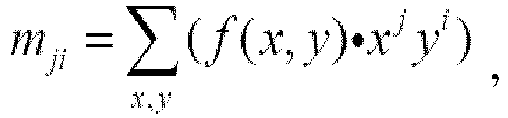 wobei die Schwerpunktkoordinaten (
x ,y ) Folgende sind: in Schritt S343 Detektieren der Triebwerke des Flugzeugs in dem quasi-kreisförmigen Bereich durch Ähnlichkeitsbestimmung; undin Schritt S344 Detektieren des Vorderrads des Flugzeugs, um die erste Position des Flugzeugs zu erhalten.
 - Verfahren nach Anspruch 3, wobei in Schritt S343 für M detektierte quasi-kreisförmige Bereiche eine Ähnlichkeit Similarityij zwischen einem i-ten quasi-kreisförmigen Bereich und einem j-ten quasi-kreisförmigen Bereich Folgende ist:
 wobei height eine Schwerpunkthöhe repräsentiert, Radius einen Radius repräsentiert und wenn die Ähnlichkeit Similarityij kleiner als ein im Voraus festgelegter Ähnlichkeitsschwellenwert ist, bestimmt wird, dass der i-te quasi-kreisförmige Bereich und der j-te quasi-kreisförmige Bereich Triebwerken der Flugzeuge entsprechen;wobei in Schritt S343, falls kein Flugzeugtriebwerk detektiert wird, eine iterative Detektion ausgeführt wird, um durch Erhöhen des Schwellenwerts für die Beurteilung von außerordentlich schwarz, des Kreisbeurteilungsschwellenwerts und des Ähnlichkeitsschwellenwerts die Schritte S341 bis S343 auszuführen; falls immer noch kein Flugzeugtriebwerk detektiert wird, auf alle außerordentlich schwarzen Bereiche eine kreisförmige 7*7-Schablone angewendet wird, um eine Öffnungsoperation auszuführen, und daraufhin die Schritte S342 bis S343 ausgeführt werden;falls immer noch kein Flugzeugtriebwerk detektiert wird, die iterative Detektion zweimal ausgeführt wird; undfalls immer noch kein Flugzeugtriebwerk detektiert wird, bestimmt wird, dass in dem Bild kein Triebwerk vorhanden ist;wobei der Schwellenwert für die Beurteilung von außerordentlich schwarz, der Kreisbeurteilungsschwellenwert und der Ähnlichkeitsschwellenwert in dieser Reihenfolge um 0,05, 0,5 und 20 erhöht werden;wobei der Schritt S344 das Vorderrad-Detektionsverfahren nach Anspruch 1 umfasst;
oderwobei der Flugzeugnachführungsschritt ferner umfasst:in Schritt S41 nach Erhalten der Positionen von Triebwerken in dem letzten Einzelbild Ausführen der Nachführung unter Verwendung eines Farbfüllalgorithmus zum Bestimmen eines Triebwerksbereichs in einem gegenwärtigen Einzelbild;in Schritt S42, falls ein Füllergebnis in Schritt S41 nicht gültig ist, Ausführen eines Schritts der Detektion und Nachführung einer dunklen Umgebung zum Durchführen der Schritte S341 und S342 unter Verwendung von Parametern für das letzte Einzelbild zum Detektieren und Nachführen des Triebwerksbereichs;in Schritt S43 nach Erhalten von Informationen hinsichtlich des Triebwerksbereichs Detektieren des Vorderrads des Flugzeugs unter Verwendung des Schritts S344, um die erste Position des Vorderrads des Flugzeugs zu erhalten;in Schritt S44 Ausführen eines Vorderrad-Notfallverarbeitungsschritts; wenn gemäß Informationen des letzten Einzelbilds und des gegenwärtigen Einzelbilds detektiert wird, dass eine Form des Vorderrads nicht richtig ist oder dass eine Position des Vorderrads offensichtlich von der in vorhergehenden Einzelbildern abweicht, Schätzen der Verlagerung des Vorderrads in dem gegenwärtigen Einzelbild auf der Grundlage der Verlagerung der Triebwerke zwischen zwei benachbarten Einzelbildern, um ein Schätzergebnis als ein Vorderrad-Nachführungsergebnis zu erhalten; falls nach mehr als N Einzelbildern kein Vorderrad detektiert werden kann, Ausgeben von Fehlerinformationen;wobei der Flugzeugortsbestimmungsschritt umfasst:in Schritt S51 Ausführen eines Kameravorrichtungskalibrierungs- und -bildkorrekturschritts, um eine Korrespondenz zwischen optischen Parametern einer Kameravorrichtung und einem geographischen Koordinatensystem zu bestimmen;in Schritt S52 Ausführen eines Flugzeugvorderrad-Abweichungsgrad-Berechnungsschritts; undin Schritt S53 Ausführen eines Schritts der Berechnung des tatsächlichen Abstands des Flugzeugvorderrads. - Verfahren nach Anspruch 4, wobei der Schritt S51 ferner umfasst:in Schritt S511 Lesen von N Kalibrierungsbildern;in Schritt S512 Ermitteln von Schachbretteckpunkten unter Verwendung einer Funktion cvFindChessboardCorners() in OpenCV, Bringen der gelesenen N Kalibrierungsbilder in die Funktion cvFindChessboardCorners(); falls das Ermitteln alle Eckpunkte erfolgreich ist, Zurückgeben von 1 durch die Funktion und Erhalten der Koordinaten der Eckpunkte in einem Bildkoordinatensystem; falls das Ermitteln aller Eckpunkte nicht erfolgreich ist, Zurückgeben von 0 durch die Funktion; undin Schritt S513 Bringen der Koordinaten der erfolgreich ermittelten Eckpunkte in einer Kalibrierungsvorlage in eine Funktion cvCalibrateCamera2() und Zurückgeben einer Parametermatrix, eines Verzerrungskoeffizienten, eines Rotationsvektors und eines Translationsvektors der Kameravorrichtung.
- Verfahren nach Anspruch 4, wobei der Schritt S52 ferner umfasst:gemäß der ersten Position (x 0, y 0) des Vorderrads des Flugzeugs, die in Schritt S43 erhalten wurde, unter Verwendung einer Beziehung zwischen Koordinaten der Position und der Führungs- und der Haltelinie Erhalten einer Geradengleichung der Führungslinie als y 1 = k 1 x 1 + b 1 und einer Geradengleichung der Haltelinie als y 2 = k 2 x 2 + b 2 , wobei ein Abstand von den Koordinaten der Position zu einer Geraden wie folgt ist:
 Bringen von (x 0, y 0) in die zwei Geradengleichungen, um d 1 und d 2 zu erhalten; wobei, falls d 2 ≥ 0 ist, angegeben wird, dass das Vorderrad des Flugzeugs über die Haltelinie hinausrollt; falls d 2 < 0 ist, angegeben wird, dass das Vorderrad des Flugzeugs nicht bei der Haltelinie angekommen ist; und zu diesem Zeitpunkt, falls k 1 > 0 ist, d 1 > 0 angibt, dass das Flugzeug nach links abweicht, und d 1 < 0 angibt, dass das Flugzeug nach rechts abweicht; und falls k 1 < 0 ist, d 1 < 0 angibt, dass das Flugzeug nach links abweicht, d 1 > 0 angibt, dass das Flugzeug nach rechts abweicht.
 - Verfahren nach Anspruch 6, wobei der Schritt S52 ferner umfasst:Bestimmen, ob | d 1 |> width / 2 ist, wobei width ein Schwellenwert gleich einer Breite des Vorderrads des detektierten Flugzeugs ist;falls | d 1 |> width / 2 ist, Bestimmen, dass das Flugzeug von der Führungslinie abweicht.
- Verfahren nach Anspruch 4, wobei der Schritt S53 ferner umfasst:Aufstellen einer Korrespondenz zwischen Bildkoordinaten und geodätischen Koordinaten;Erhalten von Bildkoordinaten von Kalibrierungspunkten, die während der Feldeinstellung in Schritt S1 verwendet wurden, Durchführen einer Anpassung an eine quadratische Kurve unter Verwendung der Bildkoordinaten durch ein Verfahren der kleinsten Fehlerquadrate, um eine Kurvenliniengleichung y = ax 2 + bx + c zu erhalten, wobei x ein Abstand in einem Bild ist, y ein tatsächlicher Abstand ist;Projizieren der Position des Vorderrads des Flugzeugs in dem Bild auf die Führungslinie entlang einer Richtung der Haltelinie, Berechnen eines euklidischen Abstands zwischen einem Projektionspunkt und einem Haltepunkt als x und Erhalten eines tatsächlichen Abstands von dem Vorderrad des Flugzeugs zu der Haltelinie unter Verwendung von y = ax2 + bx + c .
- Verfahren nach Anspruch 2, wobei das Verfahren ferner einen Schritt S6 umfasst, der nach dem Schritt S3 ausgeführt wird, wobei der Schritt S6 ein Flugzeugidentifizierungs- und -identitätsverifizierungsschritt ist, der umfasst:in Schritt S61 Ausführen einer Parameterverifizierung: Extrahieren von Flugzeugparametern in den Bildern und Vergleichen der Flugzeugparameter mit Typdaten, die in einer Datenbank vorgespeichert sind, um einen Typähnlichkeitsparameter zu erhalten;in Schritt S62 Ausführen einer Vorlagengleichheitsprüfung: Vergleichen der Bilder mit Typvorlagen, die in der Datenbank vorgespeichert sind, um einen Vorlagenähnlichkeitsparameter zu erhalten;in Schritt S63 Ausführen einer synthetischen Beurteilung: wenn der Typähnlichkeitsparameter und die Vorlagenähnlichkeit größer oder gleich einem Verifizierungsschwellenwert sind, Bestimmen, dass die Identitätsverifizierung bestanden wurde.
- Verfahren nach Anspruch 9, wobei der Schritt S61 ferner umfasst:in Schritt S611 Extrahieren eines Flugzeugtriebwerksparameters in den Bildern und Vergleichen des Flugzeugtriebwerksparameters mit einem Flugzeugtriebwerksparameter eines entsprechenden Typs, der in der Datenbank vorgespeichert ist, um ein erstes Verhältnis zu erhalten;in Schritt S612 Extrahieren eines Flugzeugflügelparameters in den Bildern und Vergleichen des Flugzeugflügelparameters mit einem Flugzeugflügelparameter des entsprechenden Typs, der in der Datenbank vorgespeichert ist, um ein zweites Verhältnis zu erhalten;in Schritt S613 Extrahieren eines Flugzeugkopfparameters in den Bildern und Vergleichen des Flugzeugkopfparameters mit einem Flugzeugkopfparameter des entsprechenden Typs, der in der Datenbank vorgespeichert ist, um ein drittes Verhältnis zu erhalten;in Schritt S614 Extrahieren eines Flugzeugseitenflossenparameters in den Bildern und Vergleichen des Flugzeugseitenflossenparameters mit einem Flugzeugseitenflossenparameter des entsprechenden Typs, der in der Datenbank vorgespeichert ist, um ein viertes Verhältnis zu erhalten; undin Schritt S615 Identifizieren des Maximalen und des Minimalen unter dem ersten Verhältnis, dem zweiten Verhältnis, dem dritten Verhältnis und dem vierten Verhältnis und Berechnen eines Verhältnisses des Minimalen zu dem Maximalen als der Typähnlichkeitsparameter;wobei der Schritt S62 ferner umfasst:in Schritt S621 Ausführen einer Gleichheitsprüfung mit einer globalen Vorlage: mit einem Gesamtbild als ein zu suchendes Bild und mit einem Standardflugzeugbild als eine Vorlage und Berechnen eines Ähnlichkeitsparameters mit einer globalen Vorlage; undin Schritt S622 Ausführen einer Gleichheitsprüfung mit einer lokalen Vorlage: mit Bildern eines Flugzeugtriebwerks, eines Flugzeugflügels, eines Flugzeugkopfs und einer Flugzeugseitenflosse, die gemäß den Schritten S611 bis S614 extrahiert wurden, als zu suchende Bilder, und mit einem Flugzeugtriebwerk, mit einem Flugzeugflügel, mit einem Flugzeugkopf und mit einer Flugzeugseitenflosse in dem Standardflugzeugbild als Vorlagen Berechnen von vier Ähnlichkeiten zwischen den zu suchenden Bildern und den Vorlagen, Entfernen der Minimalen unter den vier Ähnlichkeiten und Berechnen eines Durchschnittswerts der verbleibenden drei Ähnlichkeiten als ein lokaler Vorlagenähnlichkeitsparameter;wobei der Schritt S63 ferner umfasst:falls wenigstens zwei des Typähnlichkeitsparameters, des Ähnlichkeitsparameters mit einer globalen Vorlage und des Ähnlichkeitsparameters mit einer lokalen Vorlage größer oder gleich einem ersten Verifizierungsschwellenwert sind, Bestimmen, dass die Identitätsverifizierung bestanden wird; oderfalls alle des Typähnlichkeitsparameters, des Ähnlichkeitsparameters mit einer globalen Vorlage und des Ähnlichkeitsparameters mit einer lokalen Vorlage größer als ein zweiter Verifizierungsschwellenwert sind, Bestimmen, dass die Identitätsverifizierung bestanden wird.
- Verfahren nach Anspruch 1, wobei der Schritt 2000 ferner umfasst:in einem Erfassungsschritt Durchführen einer Laserabtastung zum horizontalen Abtasten einer Position, bei der erwartet wird, dass dort ein Flugzeugkopf eines Flugzeugs erscheint, Erhalten von Echodatenelementen auf der Grundlage der Laserabtastung und gemäß einer Beurteilungsbedingung Bestimmen, ob das Flugzeug erscheint, auf der Grundlage der Echodaten;in einem Ortsbestimmungsschritt, nachdem das Flugzeug erschienen ist, Durchführen der Laserabtastung zum horizontalen Abtasten des Flugzeugkopfs, Erhalten der Echodaten auf der Grundlage der Laserabtastung und Bestimmen einer Position einer Flugzeugnase des Flugzeugs gemäß den Echodaten; undin einem Nachführungs- und Führungsschritt, während das Flugzeug rollt, Nachführen der Position der Flugzeugnase durch Einstellen eines vertikalen Abtastwinkels der Laserabtastung.
- Verfahren nach Anspruch 11, wobei das Verfahren vor dem Erfassungsschritt ferner einen Nullpunktkalibrierungsschritt umfasst, der einen Vorrichtungsmontage-Nullpunktkalibrierungsschritt umfasst, der ausgeführt wird, wenn das Laserabtastungssystem erstmals eingebaut wird, wobei der Vorrichtungsmontage-Nullpunktkalibrierungsschritt umfasst:einen Schritt der Messung des horizontalen Nullpunkts, der umfasst:
horizontales Abtasten eines Kalibrierungsbereichs auf dem Boden mit einem festgesetzten vertikalen Abtastwinkel durch das Abtastsystem, wobei der Kalibrierungsbereich in N kleine Gebiete gleichgeteilt ist; Messen der Abstände von einem Begrenzungspunkt jedes der kleinen Gebiete und Ermitteln eines Minimalwerts unter den erhaltenen Abstandswerten; Bestimmen eines erweiterten Bereichs mit einem Begrenzungspunkt, der dem Minimalwert entspricht, als ein Mittelpunkt; und Identifizieren eines Punkts, der einem minimalen Abstandswert entspricht, als ein horizontaler Nullpunkt; undeinen Schritt der Messung des vertikalen Nullpunkts, der umfasst:
Durchführen einer Abstandsmessung bei einem vertikalen Abtastwinkel β1 durch das Abtastsystem, um einen ersten Abstandswert L1 zu erhalten, erneutes Durchführen der Abstandsmessung durch Einstellen des vertikalen Abtastwinkels β1 um einen Winkel λ, um einen zweiten Abstandswert L2 zu erhalten, und Berechnen von β1 unter Verwendung der folgenden Gleichung: wobei eine Gerade, wo sich L1 befindet, als eine Hypotenuse gewählt wird, eine Projektionslinie der Hypotenuse auf den Boden als ein Schenkel und ein Scheitelpunkt eines rechtwinkligen Dreiecks, das durch die Hypotenuse und den Schenkel gebildet ist, wobei ein eingeschlossener Winkel zwischen ihnen β1 ist, als ein vertikaler Nullpunkt gewählt wird;und wobei der Nullpunktkalibrierungsschritt ferner einen Nullpunktkorrekturschritt umfasst, der umfasst:nachdem der Vorrichtungsmontage-Nullpunktkalibrierungsschritt abgeschlossen ist, schrittweises Einstellen eines Abtastwinkels des Abtastsystems von einem Nullpunkt, bis ein im Voraus festgelegtes Bezugsobjekt ermittelt wird, und Aufzeichnen eines Abtastwinkels zu diesem Zeitpunkt als einen Korrekturwinkel; undwenn das Abtastsystem neu gestartet wird, Rückwärtseinstellen des Abtastwinkels um den Korrekturwinkel, um den Nullpunkt zu ermitteln, nachdem das im Voraus festgelegte Bezugsobjekt durch das Abtastsystem ermittelt worden ist;
undwobei die Beurteilungsbedingung ferner umfasst:A: Bestimmen, ob ein Verhältnis der Anzahl interessierender Punkte, die zusammenhängend sind und von denen einer einem minimalen Abstandswert entspricht, zu der Gesamtanzahl von Echodatenelementen größer als ein Schwellenwert ist;B: Berechnen einer Flugzeugbreite auf der Grundlage der Gesamtanzahl der Echodaten und Bestimmen, ob die Flugzeugbreite nicht kleiner als ein Breitenschwellenwert ist; undC: Berechnen einer Flugzeughöhe und Bestimmen, ob die berechnete Flugzeughöhe innerhalb eines vorgegebenen Bereichs liegt;wobei die Abstandswerte der interessierenden Punkte innerhalb eines spezifizierten Bereichs auf zwei Seiten mit einer vorgegebenen Länge liegen;und wobei in dem Erfassungsschritt, wenn die Echodaten erhalten werden, an den Echodaten eine Medianfilterung ausgeführt wird und daraufhin bestimmt wird, ob das Flugzeug erscheint;
undwobei der Ortsbestimmungsschritt ferner umfasst:Extrahieren von Zielpunkten, die auf den Flugzeugkopf fallen, aus den Echodaten und Umrechnen der Zielpunkte aus Polarkoordinatendaten in dreidimensionale räumliche Daten;Identifizieren eines Punkts mit einem minimalen Y-Richtungs-Wert aus den Zielpunkten als einen nächsten Punkt;Durchführen einer Kurvenanpassung zum Anpassen der Zielpunkte an eine Kurve und Identifizieren eines Scheitelpunkts der Kurve; undBestimmen des nächsten Punkts oder des Scheitelpunkts als die Position der Flugzeugnase gemäß einer Differenz zwischen einem X-Wert des nächsten Punkts und einem X-Wert des Scheitelpunkts;
undwobei der Nachführungs- und Führungsschritt ferner umfasst:Abtasten der Position der Flugzeugnase bei einem vorgegebenen vertikalen Abtastwinkel, während das Flugzeug rollt;Berechnen eines gegenwärtigen Flugzeugnasenpunkts gemäß den Echodaten; undvertikales Abtasten des gegenwärtigen Flugzeugnasenpunkts und Berechnen eines Änderungsbetrags des vertikalen Abtastwinkels gemäß einem Scheitelpunkt einer erhaltenen Parabel gemäß der Abtastung und Ändern des vertikalen Abtastwinkels gemäß dem Änderungsbetrag oder Berechnen des Änderungsbetrags des vertikalen Abtastwinkels gemäß dem gegenwärtigen Flugzeugnasenpunkt und Ändern des vertikalen Abtastwinkels gemäß dem Änderungsbetrag;
undwobei das Verfahren ferner einen Flugzeugtyp-Identifizierungsschritt umfasst;wobei der Flugzeugtyp-Identifizierungsschritt eine Flugzeugnasen-Höhenverifizierung und/oder eine Flugzeugkabinen-Breitenverifizierung und/oder eine Verifizierung eines Kopfluftbildprofils und/oder eine Verifizierung eines Kopfseitenansichtsprofils und/oder eine Flugzeugtriebwerkverifizierung umfasst;die Flugzeugnasen-Höhenverifizierung umfasst: falls eine Differenz zwischen der Flugzeugnasenhöhe und einer im Voraus festgelegten Flugzeugnasenhöhe innerhalb eines im Voraus festgelegten Bereichs liegt, Bestimmen, dass die Flugzeugnasen-Höhenverifizierung bestanden wurde;die Flugzeugkabinen-Breitenverifizierung umfasst: Ermitteln zweier Punkte aus den Echodaten, deren Differenz zwischen den X-Koordinaten das Maximum ist, mit einem geradlinigen Abstand zwischen den zwei Punkten als eine Flugzeugkabinenbreite, falls die Flugzeugkabinenbreite größer als ein Produkt einer theoretischen Flugzeugkabinenbreite und eines Breitenkoeffizienten ist, Bestimmen dass die Flugzeugkabinen-Breitenverifizierung bestanden wurde;die Verifizierung des Kopfluftbildprofils umfasst: Bringen der Echodaten (xi,yi,zi ), die durch horizontale Laserabtastung erhalten wurden, in eine im Voraus festgelegte Luftbildprofilgleichung y = fn (x) , Berechnen eines horizontalen Anpassungspunktfehlers
 die Verifizierung des Kopfseitenansichtsprofils umfasst: Bringen der Echodaten (xi,yi,zi ), die durch vertikale Laserabtastung erhalten wurden, in eine im Voraus festgelegte Seitenansichtsprofilgleichung z = gm (y), Berechnen eines vertikalen Anpassungspunktfehlers
 die Flugzeugtriebwerkverifizierung umfasst:Berechnen von Positionen von Triebwerken gemäß der Position der Flugzeugnase und Durchführen einer Laserabtastung, um die Positionen der Triebwerke horizontal und vertikal abzutasten;Umrechnen der Echodaten, die durch die horizontale Abtastung erhalten wurden, in dreidimensionale x-y-z-Koordinaten, Ermitteln eines nächsten Koordinatenpunkts, der am nächsten zu einem theoretischen Triebwerksmittelpunkt ist, und Ermitteln von Punkten, die aneinandergrenzend zu dem nächsten Koordinatenpunkt sind, um eine Punktmenge zu erhalten, und Berechnen eines Abstands zwischen einem am weitesten links liegenden Punkt und einem am weitesten rechts liegenden Punkt in der Punktmenge als eine Triebwerksbreite und eines Mittelpunkts zwischen dem am weitesten links liegenden Punkt und dem am weitesten rechts liegenden Punkt als eine horizontale Koordinate eines Triebwerksmittelpunkts;Umrechnung der Echodaten, die durch die vertikale Abtastung erhalten wurden, in dreidimensionale x-y-z-Koordinaten, Ermitteln eines nächsten Koordinatenpunkts, der dem theoretischen Triebwerksmittelpunkt am nächsten ist, und Ermitteln von Punkten, die aneinandergrenzend zu dem nächsten Koordinatenpunkt sind, um eine Punktmenge zu erhalten, und Berechnen eines Abstands zwischen einem obersten Punkt und einem untersten Punkt in der Punktmenge als eine Triebwerkshöhe und eines Mittelpunkts zwischen dem obersten Punkt und dem untersten Punkt als eine Höhe des Triebwerksmittelpunkts von dem Boden;Bestimmen, ob die Anzahl der Triebwerke mit einer im Voraus festgelegten Anzahl vereinbar ist, und falls die Anzahl der Triebwerke mit der im Voraus festgelegten Anzahl nicht vereinbar ist, Bestimmen, dass die Flugzeugtriebwerkverifizierung nicht bestanden wurde;Bestimmen, ob eine Differenz zwischen der horizontalen Koordinate des Triebwerksmittelpunkts und einem Standardwert einen Schwellenwert übersteigt oder ob eine Differenz zwischen der Höhe des Triebwerksmittelpunkts von dem Boden und einem Standardwert einen Schwellenwert übersteigt, und falls die Differenz zwischen der horizontalen Koordinate des Triebwerksmittelpunkts und einem Standardwert einen Schwellenwert übersteigt oder falls die Differenz zwischen der Höhe des Triebwerksmittelpunkts von dem Boden und einem Standardwert einen Schwellenwert übersteigt, Bestimmen, dass die Flugzeugtriebwerkverifizierung nicht bestanden wurde;Bestimmen, ob eine Differenz zwischen der Triebwerksbreite und einem Standardwert einen Schwellenwert übersteigt oder ob eine Differenz zwischen der Triebwerkshöhe und einem Standardwert einen Schwellenwert übersteigt, und falls die Differenz zwischen der Triebwerksbreite und einem Standardwert einen Schwellenwert übersteigt oder die Differenz zwischen der Triebwerkshöhe und einem Standardwert einen Schwellenwert übersteigt, Bestimmen, dass die Flugzeugtriebwerkverifizierung nicht bestanden wurde.
 - Verfahren nach Anspruch 1, wobei die Fusionsregel ferner umfasst:Festsetzen einer nichtleeren Grundmenge D = {∅, h,
h , H} unter Verwendung eines Fusionsverfahrens auf der Grundlage der D-S-Theorie, wobei h repräsentiert, dass der Flugzeugtyp richtig ist,h repräsentiert, dass der Flugzeugtyp falsch ist, H = {h,h } repräsentiert, dass der Flugzeugtyp richtig oder falsch sein könnte und einstweilig nicht bestimmt werden kann, und ∅ ein unmögliches Ereignis repräsentiert;Festsetzen einer Massefunktion m 1 (·) des Teilsystems für maschinelles Sehen und einer Massefunktion m 2 (·) des Laserabtastungs-Teilsystems und wobei die folgende Bedingung erfüllt ist: mit
mit
 m 2 (h) und m 2 (
h ) sich gemäß einer Prioritätsbestimmungsfolge ändern, die durch das Laserabtastungs-Teilsystem im Voraus festgelegt worden ist;Berechnen einer orthogonalen Summe der Massefunktionen: mit
mit falls
falls wobei ε 1 und ε 2 im Voraus festgelegte Schwellenwerte sind, Erzeugen eines Fusionsergebnisses, das angibt, dass der Flugzeugtyp richtig ist und dass die Identitätsverifizierung bestanden wird;falls:
- Flugzeug-Andockführungs- und -Typidentifizierungsvorrichtung, die umfasst:ein Teilsystem (1000) für maschinelles Sehen, das dafür konfiguriert ist, durch Bilderfassung Bilder zu erhalten und durch Berechnen auf der Grundlage der Bilder eine erste Position eines Vorderrads eines Flugzeugs zu erhalten;ein Laserabtastungs-Teilsystem (2000), das dafür konfiguriert ist, mittels Laserabtastung eine Position einer Flugzeugnase des Flugzeugs zu erhalten und durch Berechnen eine zweite Position des Vorderrads des Flugzeugs zu erhalten; undeine Fusionsvorrichtung (3000), die dafür konfiguriert ist, in Bezug auf die erste Position und die zweite Position des Vorderrads des Flugzeugs gemäß einer Fusionsregel eine Fusion auszuführen, um eine Abweichung des Vorderrads des Flugzeugs zu identifizieren;wobei die Fusionsregel umfasst:falls das Vorderrad des Flugzeugs von der Führungslinie abweicht:Bestimmen, ob ein Abstand zwischen x-Koordinaten der ersten Position und der zweiten Position des Vorderrads des Flugzeugs kleiner oder gleich einem Schwellenwert ist; falls der Abstand kleiner oder gleich dem Schwellenwert ist, Erhalten des durch das Teilsystem für maschinelles Sehen berechneten Abweichungsgrads des Vorderrads des Flugzeugs; falls der Abstand größer als der Schwellenwert ist, Ausführen einer glatten Filterung an der ersten Position und an der zweiten Position des Vorderrads des Flugzeugs, um Abweichungsinformationen bereitzustellen, die angeben, wie das Vorderrad des Flugzeugs von der Führungslinie abweicht;wobei der durch das Teilsystem für maschinelles Sehen berechnete Abweichungsgrad des Vorderrads des Flugzeugs wie folgt bestimmt wird:
Erhalten von Koordinaten der ersten Position des Vorderrads gemäß einem Ergebnis eines Vorderrad-Nachführungsschritts; wobei in dem Vorderrad-Nachführungsschritt ein Vorderrad-Detektionsverfahren verwendet wird, das enthält:Quantifizieren von 256 Graustufen in 64 Graustufen in einem Suchbereich des Bilds, Suchen eines ersten Spitzenwerts und eines ersten Tals in dem quantisierten 64-Graustufen-Histogramm, wobei eine beste Spitzenposition BestPeak und eine beste Talposition BestValley in dem ursprünglichen 256-Graustufen-Histogramm wie folgt definiert sind:
 wobei hist256(i) die Gesamtanzahl von Pixeln mit einer Graustufe i in dem 256-Graustufen-Histogramm ist;Aufteilen der Graustufen unter Verwendung von BestValley und für Teile, die eine kleinere Graustufe als das BestValley aufweisen, Entfernen unzusammenhängender Punkte mit einer verhältnismäßig kleinen Fläche und Ausführen einer Abschlussoperation an dem Bild unter Verwendung eines flachen ellipsenförmig strukturierenden Elements; undfür alle Grafiken Berechnen von Hu-Moment-Merkmalen siebenter Ordnung von Begrenzungen, Vergleichen der Hu-Moment-Merkmale siebenter Ordnung mit Momentmerkmalen eines im Voraus festgelegten Standardvorderradmodells und falls die Ähnlichkeit kleiner als ein Schwellenwert ist, Bestimmen, dass eine mittlere Grafik das Vorderrad ist;Erhalten zugehöriger Positionsinformationen über die Führungslinie und eine Haltelinie auf der Grundlage der Felddefinierung; undBestimmen des Abweichungsgrads des Vorderrads des Flugzeugs unter Verwendung der Kenntnis der Beziehung zwischen einem Mittelpunkt und einer Geraden in der Algebra;falls es einen Abstand gibt, der vor dem Vorderrad des Flugzeugs zu der Haltelinie verbleibt:
Bestimmen, ob es eine anomale Schwankung der zweiten Position des Vorderrads des Flugzeugs gibt; falls es keine derartige anomale Schwankung gibt, Erhalten der zweiten Position des Vorderrads des Flugzeugs als den Abstand, der von dem Vorderrad des Flugzeugs zu der Haltelinie verbleibt; falls es eine derartige anomale Schwankung gibt, Erhalten eines durchschnittlichen Differenzwerts von N vorhergehenden Differenzwerten zwischen Positionen des Vorderrads des Flugzeugs, die durch das Teilsystem für maschinelles Sehen und durch das Laserabtastungs-Teilsystem erhalten wurden, und Berechnen einer Summe einer Position des Vorderrads des Flugzeugs, die durch das Teilsystem für maschinelles Sehen dieses Mal erhalten wurde, und des durchschnittlichen Differenzwerts als der Abstand, der von dem Vorderrad des Flugzeugs zu der Haltelinie verbleibt.
Applications Claiming Priority (2)
| Application Number | Priority Date | Filing Date | Title |
|---|---|---|---|
| CN201410377430.5A CN105302151B (zh) | 2014-08-01 | 2014-08-01 | 一种飞机入坞引导和机型识别的系统及方法 |
| PCT/CN2015/083205 WO2016015546A1 (zh) | 2014-08-01 | 2015-07-02 | 一种飞机入坞引导和机型识别的系统及方法 |
Publications (4)
| Publication Number | Publication Date |
|---|---|
| EP3196863A1 EP3196863A1 (de) | 2017-07-26 |
| EP3196863A4 EP3196863A4 (de) | 2018-03-21 |
| EP3196863B1 true EP3196863B1 (de) | 2023-12-06 |
| EP3196863C0 EP3196863C0 (de) | 2023-12-06 |
Family
ID=55199531
Family Applications (1)
| Application Number | Title | Priority Date | Filing Date |
|---|---|---|---|
| EP15827975.2A Active EP3196863B1 (de) | 2014-08-01 | 2015-07-02 | System und verfahren zur flugzeugandockführung und zur flugzeugtypidentifizierung |
Country Status (5)
| Country | Link |
|---|---|
| US (1) | US10255520B2 (de) |
| EP (1) | EP3196863B1 (de) |
| CN (1) | CN105302151B (de) |
| ES (1) | ES2967980T3 (de) |
| WO (1) | WO2016015546A1 (de) |
Families Citing this family (78)
| Publication number | Priority date | Publication date | Assignee | Title |
|---|---|---|---|---|
| US10127448B2 (en) * | 2014-08-27 | 2018-11-13 | Bae Systems Information And Electronic Systems Integration Inc. | Method and system for dismount detection in low-resolution UAV imagery |
| WO2016171263A1 (ja) * | 2015-04-22 | 2016-10-27 | 新日鐵住金株式会社 | 形状測定装置及び形状測定方法 |
| TWI604422B (zh) * | 2016-03-23 | 2017-11-01 | 業群資訊股份有限公司 | 航空器導引過程的監控系統以及其監控方法 |
| CN107277433B (zh) * | 2016-04-06 | 2019-12-13 | 业群资讯股份有限公司 | 航空器导引过程的监控系统以及其监控方法 |
| GB2565675B (en) * | 2016-05-05 | 2021-12-01 | Walmart Apollo Llc | Systems and methods for collecting and processing image data |
| WO2018034615A1 (en) * | 2016-08-15 | 2018-02-22 | Singapore Technologies Dynamics Pte Ltd | Automatic passenger boarding bridge docking system |
| CN106128170A (zh) * | 2016-08-24 | 2016-11-16 | 桂林信通科技有限公司 | 一种飞机泊位智能指示系统 |
| CN107045677A (zh) * | 2016-10-14 | 2017-08-15 | 北京石油化工学院 | 一种危化品仓库障碍物扫描定位还原方法、装置及系统 |
| US10629072B2 (en) * | 2016-10-20 | 2020-04-21 | Ford Global Technologies, Llc | LIDAR and vision vehicle sensing |
| CN106530354B (zh) * | 2016-10-31 | 2020-01-14 | 纵目科技(上海)股份有限公司 | 一种图像处理装置、图像校正、标定点查找方法及系统 |
| RU2757549C2 (ru) * | 2017-01-06 | 2021-10-18 | Аурора Флайт Сайенсиз Корпорейшн | Система и способ для предупреждения столкновений беспилотного летательного аппарата |
| CN106976567A (zh) * | 2017-01-11 | 2017-07-25 | 天津华德宝航翼光电科技有限公司 | 一种飞机停泊过程方向引导动态显示系统 |
| RU2708346C1 (ru) * | 2017-03-22 | 2019-12-05 | Александр Иванович Стучилин | Способ идентификации типа самолета средствами пассивной оптической локации и устройство для его осуществления |
| CN107220973A (zh) * | 2017-06-29 | 2017-09-29 | 浙江中烟工业有限责任公司 | 基于Python+OpenCV的六边形中空滤棒快速检测方法 |
| WO2019037129A1 (en) * | 2017-08-25 | 2019-02-28 | Beijing Didi Infinity Technology And Development Co., Ltd. | METHODS AND SYSTEMS FOR DETECTING ENVIRONMENTAL INFORMATION OF A VEHICLE |
| DE102017215614A1 (de) * | 2017-09-05 | 2019-03-07 | Osram Gmbh | Stochastisch getaktete Bilderzeugung eines Lidar-System |
| JP6949138B2 (ja) | 2017-12-19 | 2021-10-13 | 日本音響エンジニアリング株式会社 | 航空機運航実績情報の収集装置 |
| CN108132672A (zh) * | 2017-12-20 | 2018-06-08 | 襄阳宏伟航空器有限责任公司 | 一种热气球飞行高度的自动控制方法 |
| CN109961455B (zh) | 2017-12-22 | 2022-03-04 | 杭州萤石软件有限公司 | 一种目标检测方法及装置 |
| US10752158B2 (en) * | 2018-02-07 | 2020-08-25 | Massachusetts Institute Of Technology | Methods and apparatus for imaging through fog |
| CN108960236B (zh) * | 2018-06-27 | 2021-08-27 | 浙江理工大学 | 基于二维码匹配与图像识别的指针式仪表识别方法 |
| KR102545105B1 (ko) * | 2018-10-10 | 2023-06-19 | 현대자동차주식회사 | 차량용 허위 타겟 판별 장치 및 그의 허위 타겟 판별 방법과 그를 포함하는 차량 |
| CN109543533B (zh) * | 2018-10-22 | 2023-05-09 | 捻果科技(深圳)有限公司 | 一种用于机场作业人员管理的自动识别方法 |
| CN109711036B (zh) * | 2018-12-24 | 2023-05-23 | 中国航空工业集团公司西安飞机设计研究所 | 飞行控制系统试验结果的评估方法 |
| CN111368603B (zh) * | 2018-12-26 | 2023-04-07 | 北京眼神智能科技有限公司 | 遥感图像的飞机分割方法、装置、可读存储介质及设备 |
| EP3680689A1 (de) * | 2019-01-11 | 2020-07-15 | ADB Safegate Sweden AB | Flughafen-standanordnung |
| CN109752730B (zh) * | 2019-02-25 | 2024-02-27 | 佛山市奇创自动化设备有限公司 | 一种基于v槽检测的激光定位方法及系统 |
| CN111637834B (zh) * | 2019-03-01 | 2023-01-10 | 北京伟景智能科技有限公司 | 一种三维数据测量装置及方法 |
| CN109887343B (zh) * | 2019-04-04 | 2020-08-25 | 中国民航科学技术研究院 | 一种航班地服保障节点自动采集监测系统及方法 |
| CN110097596B (zh) * | 2019-04-30 | 2023-06-09 | 湖北大学 | 一种基于opencv的目标检测系统 |
| CN110113510B (zh) * | 2019-05-27 | 2021-02-26 | 杭州国翌科技有限公司 | 一种实时视频图像增强方法和高速相机系统 |
| CN112034831B (zh) * | 2019-06-04 | 2021-11-09 | 深圳中集天达空港设备有限公司 | 登机桥接靠飞机的方法及电子设备以及存储介质 |
| CN110516739B (zh) * | 2019-08-27 | 2022-12-27 | 创新先进技术有限公司 | 一种证件识别方法、装置及设备 |
| CN110728668B (zh) * | 2019-10-09 | 2022-06-28 | 中国科学院光电技术研究所 | 一种小目标形态保持的空域高通滤波器 |
| CN110646212B (zh) * | 2019-10-23 | 2022-01-25 | 成都飞机工业(集团)有限责任公司 | 一种飞机发动机标定的新方法 |
| EP3813039A1 (de) * | 2019-10-24 | 2021-04-28 | thyssenkrupp Airport Solutions, S.A. | Verfahren zur beobachtung von bodenverkehr auf einem flughafen |
| CN111079663B (zh) * | 2019-12-19 | 2022-01-11 | 深圳云天励飞技术股份有限公司 | 高空抛物的监测方法、装置、电子设备及存储介质 |
| CN111522345B (zh) * | 2020-04-30 | 2024-02-27 | 电子科技大学 | 一种登机桥对接舱门的轮位控制方法 |
| US11538349B2 (en) | 2020-08-03 | 2022-12-27 | Honeywell International Inc. | Multi-sensor data fusion-based aircraft detection, tracking, and docking |
| CN112164086B (zh) * | 2020-10-12 | 2024-07-19 | 华雁智能科技(集团)股份有限公司 | 一种精细化的图像边缘信息确定方法、系统及电子设备 |
| CN112381029B (zh) * | 2020-11-24 | 2023-11-14 | 沈阳建筑大学 | 一种基于欧氏距离的机载LiDAR数据建筑物提取方法 |
| CN112597892B (zh) * | 2020-12-23 | 2022-09-23 | 重庆邮电大学 | 一种汽车座舱内遗留物检测系统及检测方法 |
| CN113013781B (zh) * | 2021-02-05 | 2022-04-01 | 安阳一都网络科技有限公司 | 基于图像处理的激光发射及动态校准装置、方法、设备和介质 |
| CN113052190B (zh) * | 2021-04-01 | 2022-05-31 | 威海职业学院(威海市技术学院) | 一种基于图像处理的视觉辅助系统及方法 |
| KR102567249B1 (ko) * | 2021-04-21 | 2023-08-21 | (주)안세기술 | 3차원 레이저 스캐너를 이용한 항공기 주기유도 시스템 및 이를 이용한 항공기 주기 제어방법 |
| CN113204244B (zh) * | 2021-04-23 | 2022-06-03 | 电子科技大学 | 一种基于定位导航的登机桥对接方法 |
| US12372656B2 (en) * | 2021-06-09 | 2025-07-29 | Honeywell International Inc. | Aircraft identification |
| CN113610133B (zh) * | 2021-07-30 | 2024-05-28 | 上海德衡数据科技有限公司 | 一种激光数据和视觉数据融合方法及系统 |
| CN113343957B (zh) * | 2021-08-06 | 2021-12-21 | 深圳市信润富联数字科技有限公司 | 基于三维视觉的轮毂识别方法、装置、设备及存储介质 |
| KR102347972B1 (ko) * | 2021-08-18 | 2022-01-07 | 주식회사 아이지아이에스 | 파노라마 영상 제공시스템 |
| CN113432558B (zh) * | 2021-08-25 | 2021-11-26 | 山东捷瑞数字科技股份有限公司 | 一种基于激光的不规则物体表面积的测量装置及方法 |
| CN114001658B (zh) * | 2021-10-29 | 2022-08-30 | 合肥工业大学 | 一种冰箱发泡夹具腔内自动检测装置及其方法 |
| EP4177864A1 (de) * | 2021-11-09 | 2023-05-10 | TK Airport Solutions, S.A. | Visuelles andockführungssystem |
| CN114067147B (zh) * | 2021-11-12 | 2022-12-16 | 北京航空航天大学 | 一种基于局部形状匹配的舰船目标确认方法 |
| CN114140497B (zh) * | 2021-11-15 | 2024-12-06 | 中国科学院自动化研究所 | 目标车辆3d实时追踪方法及系统 |
| CN114543664B (zh) * | 2021-12-30 | 2024-05-07 | 中国航空工业集团公司沈阳飞机设计研究所 | 一种基于激光扫描的加油锥套定位方法及装置 |
| US12020346B2 (en) * | 2022-01-11 | 2024-06-25 | Rtx Corporation | Aircraft communication visualization |
| CN114594789B (zh) * | 2022-03-03 | 2024-06-21 | 飞循智航(成都)科技有限公司 | 一种无人机回收引导方法、装置及电子设备 |
| CN114674249B (zh) * | 2022-03-28 | 2023-02-07 | 上海大学 | 一种筒体嵌套装配对中的视觉测量引导装置、方法及系统 |
| CN114674231B (zh) * | 2022-03-28 | 2022-12-20 | 大连理工大学 | 一种基于单片机的便携式在线视觉位移测量系统 |
| CN114821377B (zh) * | 2022-04-29 | 2025-12-19 | 中国人民解放军空军工程大学航空机务士官学校 | 一种基于特征融合的高动态多目标无人机检测方法 |
| CN114863332B (zh) * | 2022-04-29 | 2024-08-27 | 华中科技大学 | 一种基于事件相机的雨滴检测方法 |
| CN114954997B (zh) * | 2022-07-14 | 2022-12-13 | 成都飞机工业(集团)有限责任公司 | 一种舱门装配阶差的控制方法、装置、设备及介质 |
| DE102022134637A1 (de) * | 2022-12-22 | 2024-06-27 | Rheinmetall Air Defence Ag | Verfahren zur fernsteuerung einer fluggastbrücke |
| CN116758271B (zh) * | 2023-05-09 | 2025-11-14 | 中国航空无线电电子研究所 | 飞行指引符号图像识别方法 |
| CN116300971B (zh) * | 2023-05-17 | 2023-09-01 | 中国民航大学 | 民航飞机的牵引滑行控制方法、装置、牵引车及存储介质 |
| US20240420445A1 (en) * | 2023-06-14 | 2024-12-19 | Honeywell International Inc. | Aircraft maintenance system and methods |
| CN116452840B (zh) * | 2023-06-19 | 2023-08-18 | 济宁联威车轮制造有限公司 | 一种基于数控机床的汽车零部件组装位置视觉校对系统 |
| CN117022662A (zh) * | 2023-07-11 | 2023-11-10 | 北京华翼助航技术开发有限公司 | 一种大角度引导飞机停靠系统、方法及存储介质 |
| CN117086500B (zh) * | 2023-08-17 | 2024-06-25 | 深圳市大德激光技术有限公司 | 一种激光蚀刻设备电气控制系统 |
| CN116804865B (zh) * | 2023-08-28 | 2023-12-08 | 成都飞机工业(集团)有限责任公司 | 一种三轴自动化程编特征识别与刀轨生成方法 |
| CN117152144B (zh) * | 2023-10-30 | 2024-01-30 | 潍坊华潍新材料科技有限公司 | 基于图像处理的导辊监测方法及装置 |
| CN117452956A (zh) * | 2023-12-26 | 2024-01-26 | 天津瀚海蓝帆海洋科技有限公司 | 一种具有电子围栏应急系统的水下机器人 |
| CN117830731B (zh) * | 2024-01-02 | 2024-06-28 | 北京蓝耘科技股份有限公司 | 多维并行调度方法 |
| CN118314359B (zh) * | 2024-03-11 | 2025-05-13 | 广东国工智能科技有限公司 | 高速机械执行末端防抖动计算调控方法、系统及加工系统 |
| CN117949917B (zh) * | 2024-03-26 | 2024-05-28 | 中国民航大学 | 机坪杂波环境下鸟类目标的识别方法和存储介质 |
| CN120308352A (zh) * | 2025-03-26 | 2025-07-15 | 西安睿诺航空装备有限公司 | 一种机场无车辆保障系统 |
| CN120394381A (zh) * | 2025-05-13 | 2025-08-01 | 苏州博睿测控设备有限公司 | 电动执行器的装配检测方法、装置、终端及存储介质 |
Family Cites Families (26)
| Publication number | Priority date | Publication date | Assignee | Title |
|---|---|---|---|---|
| FR2637694B1 (fr) * | 1988-10-07 | 1991-10-18 | Electr Et Entreprises | Dispositif de detection de la position d'un mobile, notamment d'un aeronef, dans un plan |
| JP2667924B2 (ja) * | 1990-05-25 | 1997-10-27 | 東芝テスコ 株式会社 | 航空機ドッキングガイダンス装置 |
| US6324489B1 (en) * | 1999-10-29 | 2001-11-27 | Safegate International Ab | Aircraft identification and docking guidance systems |
| DE4301637C2 (de) * | 1993-01-22 | 1997-05-22 | Daimler Benz Aerospace Ag | Verfahren zum Andocken eines Flugzeuges an eine Fluggastbrücke eines Flughafengebäudes |
| BR9408629A (pt) * | 1994-10-14 | 1998-12-01 | Airport Tech Scandinavia | Sistema e processo para verificar a forma de um objeto detectado e sistema para rastrear um objeto |
| US5675661A (en) * | 1995-10-12 | 1997-10-07 | Northrop Grumman Corporation | Aircraft docking system |
| BR9707716A (pt) * | 1996-02-29 | 2000-01-04 | Siemens Ag | Sistema de condução de aeroportos, especialmente sistema de condução de tráfego no solo de tráfego no solo de aeroportos |
| FR2763727B1 (fr) * | 1997-05-20 | 1999-08-13 | Sagem | Procede et systeme de guidage d'un avion vers un poste d'accostage |
| US6353793B1 (en) * | 1999-02-01 | 2002-03-05 | Aero Modifications & Consulting, Llc | System and apparatus for determining the center of gravity of an aircraft |
| US6564142B2 (en) * | 1999-02-01 | 2003-05-13 | Aero Modifications & Consulting, L.L.C. | System and apparatus for determining the center of gravity of an aircraft |
| US6563432B1 (en) | 2001-01-12 | 2003-05-13 | Safegate International Ab | Aircraft docking system and method with automatic checking of apron and detection of fog or snow |
| ES2206016B1 (es) * | 2002-04-04 | 2005-07-16 | Team Tecnologia Europea Aplicada Al Movimiento, S.L. | Procedimiento y aparato para el control de la posicion de aeronaves en maniobras en tierra despues del aterrizaje. |
| US6928363B2 (en) | 2002-09-20 | 2005-08-09 | The Boeing Company | Autotiller control system for aircraft |
| JP4402400B2 (ja) * | 2003-08-28 | 2010-01-20 | オリンパス株式会社 | 物体認識装置 |
| CN1300750C (zh) * | 2005-03-07 | 2007-02-14 | 张积洪 | 飞机泊位机型自动识别与指示系统 |
| US7702453B2 (en) * | 2007-03-23 | 2010-04-20 | Dew Engineering And Development Ulc | System and method for guiding an aircraft to a stopping position |
| FR2924831B1 (fr) * | 2007-12-11 | 2010-11-19 | Airbus France | Procede et dispositif de generation d'un ordre de vitesse de lacet pour un aeronef roulant au sol |
| CN101739694B (zh) * | 2010-01-07 | 2011-10-05 | 北京智安邦科技有限公司 | 基于图像分析的高压输电线的超高检测的方法及装置 |
| CN102252619A (zh) * | 2011-04-21 | 2011-11-23 | 中国民航大学 | 飞机泊位过程中移动距离测量与显示系统 |
| FR2982062B1 (fr) * | 2011-10-27 | 2013-12-13 | Airbus Operations Sas | Procede et un dispositif d'aide a la garantie de la precision et de l'integrite d'une position d'un aeronef au sol. |
| US9280155B2 (en) * | 2011-12-02 | 2016-03-08 | Borealis Technical Limited | Aircraft ground travel traction control system and method |
| CN102567093A (zh) * | 2011-12-20 | 2012-07-11 | 广州粤嵌通信科技股份有限公司 | 一种应用于视觉泊位自动引导系统的泊位机型识别方法 |
| WO2013141605A1 (ko) | 2012-03-21 | 2013-09-26 | (주)안세기술 | 항공기의 기종판별 및 주기유도를 위한 시스템 및 방법 |
| CN103049788B (zh) * | 2012-12-24 | 2015-11-18 | 南京航空航天大学 | 基于计算机视觉的待过行人数目的检测系统及方法 |
| CN103177586A (zh) * | 2013-03-05 | 2013-06-26 | 天津工业大学 | 一种基于机器视觉的城市交叉路口多车道车流量检测方法 |
| CN103853893B (zh) * | 2014-03-26 | 2016-10-26 | 中国民用航空总局第二研究所 | 一种从点云数据检测飞机姿态的参数模型匹配方法 |
-
2014
- 2014-08-01 CN CN201410377430.5A patent/CN105302151B/zh active Active
-
2015
- 2015-07-02 EP EP15827975.2A patent/EP3196863B1/de active Active
- 2015-07-02 WO PCT/CN2015/083205 patent/WO2016015546A1/zh not_active Ceased
- 2015-07-02 ES ES15827975T patent/ES2967980T3/es active Active
- 2015-07-02 US US15/329,990 patent/US10255520B2/en active Active
Also Published As
| Publication number | Publication date |
|---|---|
| WO2016015546A1 (zh) | 2016-02-04 |
| EP3196863A4 (de) | 2018-03-21 |
| CN105302151B (zh) | 2018-07-13 |
| EP3196863A1 (de) | 2017-07-26 |
| CN105302151A (zh) | 2016-02-03 |
| ES2967980T3 (es) | 2024-05-06 |
| US20170262732A1 (en) | 2017-09-14 |
| US10255520B2 (en) | 2019-04-09 |
| EP3196863C0 (de) | 2023-12-06 |
Similar Documents
| Publication | Publication Date | Title |
|---|---|---|
| EP3196863B1 (de) | System und verfahren zur flugzeugandockführung und zur flugzeugtypidentifizierung | |
| US10290219B2 (en) | Machine vision-based method and system for aircraft docking guidance and aircraft type identification | |
| US10562644B2 (en) | System and method for aircraft docking guidance and aircraft type identification | |
| Hautiere et al. | Automatic fog detection and estimation of visibility distance through use of an onboard camera | |
| EP2096602B1 (de) | Verfahren und Vorrichtung zur Startbahnsegmentierung mittels Sensoranalyse | |
| CN117492026B (zh) | 结合激光雷达扫描的铁路货车装载状态检测方法及系统 | |
| EP2741267B1 (de) | Fahrzeugerkennungsvorrichtung und fahrzeugerkennungsverfahren | |
| CN105447431A (zh) | 一种基于机器视觉的入坞飞机跟踪定位方法及系统 | |
| CN117763423A (zh) | 一种基于深度学习的智能汽车激光雷达点云异常检测方法 | |
| CN112683228A (zh) | 单目相机测距方法及装置 | |
| CN105335764B (zh) | 一种入坞飞机机型识别验证系统及方法 | |
| CN111539279A (zh) | 道路限高高度检测方法、装置、设备及存储介质 | |
| Barua et al. | An efficient method of lane detection and tracking for highway safety | |
| CN105447496A (zh) | 一种基于机器视觉的入坞飞机机型识别验证方法和系统 | |
| Tian | Identification of weather conditions related to roadside lidar data | |
| RU2857139C1 (ru) | Способ формирования цифровых портретов наземных объектов воздушной разведки | |
| CN121305505B (zh) | 一种基于ai与多尺度融合的道路病害识别方法 | |
| KR102952877B1 (ko) | 라이다 센서를 이용한 객체 추적 장치 및 방법 | |
| US20240096090A1 (en) | Damage Detection and Image Alignment Based on Polygonal Representation of Objects | |
| Hautière¹ et al. | Perception through scattering media for autonomous vehicles | |
| Zhang et al. | 3-D Modeling of Traffic Accidents Scenes Using a UAV-Borne SSL-Camera System | |
| Niblock et al. | Autonomous tracking system for airport lighting quality control. | |
| CN121284297A (zh) | 一种基于人工智能的视频分析方法及系统 | |
| CN121415367A (zh) | 一种基于车轮检测的路侧停车状态判断方法及系统 | |
| CN114066968A (zh) | 一种基于视觉图像处理的车速测量方法 |
Legal Events
| Date | Code | Title | Description |
|---|---|---|---|
| STAA | Information on the status of an ep patent application or granted ep patent |
Free format text: STATUS: THE INTERNATIONAL PUBLICATION HAS BEEN MADE |
|
| PUAI | Public reference made under article 153(3) epc to a published international application that has entered the european phase |
Free format text: ORIGINAL CODE: 0009012 |
|
| STAA | Information on the status of an ep patent application or granted ep patent |
Free format text: STATUS: REQUEST FOR EXAMINATION WAS MADE |
|
| 17P | Request for examination filed |
Effective date: 20170301 |
|
| AK | Designated contracting states |
Kind code of ref document: A1 Designated state(s): AL AT BE BG CH CY CZ DE DK EE ES FI FR GB GR HR HU IE IS IT LI LT LU LV MC MK MT NL NO PL PT RO RS SE SI SK SM TR |
|
| AX | Request for extension of the european patent |
Extension state: BA ME |
|
| DAV | Request for validation of the european patent (deleted) | ||
| DAX | Request for extension of the european patent (deleted) | ||
| A4 | Supplementary search report drawn up and despatched |
Effective date: 20180215 |
|
| RIC1 | Information provided on ipc code assigned before grant |
Ipc: G06K 9/00 20060101ALI20180210BHEP Ipc: G06K 9/36 20060101ALI20180210BHEP Ipc: G08G 5/06 20060101AFI20180210BHEP Ipc: G06K 9/20 20060101ALI20180210BHEP Ipc: H04N 7/00 20110101ALI20180210BHEP Ipc: G01S 17/06 20060101ALI20180210BHEP Ipc: G01S 17/88 20060101ALI20180210BHEP Ipc: G06K 9/60 20060101ALI20180210BHEP Ipc: B64F 1/00 20060101ALI20180210BHEP |
|
| STAA | Information on the status of an ep patent application or granted ep patent |
Free format text: STATUS: EXAMINATION IS IN PROGRESS |
|
| 17Q | First examination report despatched |
Effective date: 20190319 |
|
| RAP1 | Party data changed (applicant data changed or rights of an application transferred) |
Owner name: SHENZHEN CIMC-TIANDA AIRPORT SUPPORT LTD. |
|
| REG | Reference to a national code |
Ref country code: DE Ref legal event code: R079 Free format text: PREVIOUS MAIN CLASS: G08G0005060000 Ipc: G06V0020580000 Ref country code: DE Ref legal event code: R079 Ref document number: 602015086847 Country of ref document: DE Free format text: PREVIOUS MAIN CLASS: G08G0005060000 Ipc: G06V0020580000 |
|
| GRAP | Despatch of communication of intention to grant a patent |
Free format text: ORIGINAL CODE: EPIDOSNIGR1 |
|
| STAA | Information on the status of an ep patent application or granted ep patent |
Free format text: STATUS: GRANT OF PATENT IS INTENDED |
|
| RIC1 | Information provided on ipc code assigned before grant |
Ipc: G06V 20/56 20220101ALI20230123BHEP Ipc: G06V 20/58 20220101AFI20230123BHEP |
|
| INTG | Intention to grant announced |
Effective date: 20230213 |
|
| GRAJ | Information related to disapproval of communication of intention to grant by the applicant or resumption of examination proceedings by the epo deleted |
Free format text: ORIGINAL CODE: EPIDOSDIGR1 |
|
| STAA | Information on the status of an ep patent application or granted ep patent |
Free format text: STATUS: EXAMINATION IS IN PROGRESS |
|
| GRAP | Despatch of communication of intention to grant a patent |
Free format text: ORIGINAL CODE: EPIDOSNIGR1 |
|
| STAA | Information on the status of an ep patent application or granted ep patent |
Free format text: STATUS: GRANT OF PATENT IS INTENDED |
|
| INTC | Intention to grant announced (deleted) | ||
| INTG | Intention to grant announced |
Effective date: 20230705 |
|
| GRAS | Grant fee paid |
Free format text: ORIGINAL CODE: EPIDOSNIGR3 |
|
| GRAA | (expected) grant |
Free format text: ORIGINAL CODE: 0009210 |
|
| STAA | Information on the status of an ep patent application or granted ep patent |
Free format text: STATUS: THE PATENT HAS BEEN GRANTED |
|
| AK | Designated contracting states |
Kind code of ref document: B1 Designated state(s): AL AT BE BG CH CY CZ DE DK EE ES FI FR GB GR HR HU IE IS IT LI LT LU LV MC MK MT NL NO PL PT RO RS SE SI SK SM TR |
|
| REG | Reference to a national code |
Ref country code: GB Ref legal event code: FG4D |
|
| REG | Reference to a national code |
Ref country code: DE Ref legal event code: R096 Ref document number: 602015086847 Country of ref document: DE |
|
| REG | Reference to a national code |
Ref country code: CH Ref legal event code: EP |
|
| REG | Reference to a national code |
Ref country code: IE Ref legal event code: FG4D |
|
| U01 | Request for unitary effect filed |
Effective date: 20240105 |
|
| U07 | Unitary effect registered |
Designated state(s): AT BE BG DE DK EE FI FR IT LT LU LV MT NL PT SE SI Effective date: 20240115 |
|
| PG25 | Lapsed in a contracting state [announced via postgrant information from national office to epo] |
Ref country code: GR Free format text: LAPSE BECAUSE OF FAILURE TO SUBMIT A TRANSLATION OF THE DESCRIPTION OR TO PAY THE FEE WITHIN THE PRESCRIBED TIME-LIMIT Effective date: 20240307 |
|
| PG25 | Lapsed in a contracting state [announced via postgrant information from national office to epo] |
Ref country code: GR Free format text: LAPSE BECAUSE OF FAILURE TO SUBMIT A TRANSLATION OF THE DESCRIPTION OR TO PAY THE FEE WITHIN THE PRESCRIBED TIME-LIMIT Effective date: 20240307 |
|
| REG | Reference to a national code |
Ref country code: ES Ref legal event code: FG2A Ref document number: 2967980 Country of ref document: ES Kind code of ref document: T3 Effective date: 20240506 |
|
| PG25 | Lapsed in a contracting state [announced via postgrant information from national office to epo] |
Ref country code: RS Free format text: LAPSE BECAUSE OF FAILURE TO SUBMIT A TRANSLATION OF THE DESCRIPTION OR TO PAY THE FEE WITHIN THE PRESCRIBED TIME-LIMIT Effective date: 20231206 Ref country code: NO Free format text: LAPSE BECAUSE OF FAILURE TO SUBMIT A TRANSLATION OF THE DESCRIPTION OR TO PAY THE FEE WITHIN THE PRESCRIBED TIME-LIMIT Effective date: 20240306 Ref country code: HR Free format text: LAPSE BECAUSE OF FAILURE TO SUBMIT A TRANSLATION OF THE DESCRIPTION OR TO PAY THE FEE WITHIN THE PRESCRIBED TIME-LIMIT Effective date: 20231206 |
|
| PG25 | Lapsed in a contracting state [announced via postgrant information from national office to epo] |
Ref country code: IS Free format text: LAPSE BECAUSE OF FAILURE TO SUBMIT A TRANSLATION OF THE DESCRIPTION OR TO PAY THE FEE WITHIN THE PRESCRIBED TIME-LIMIT Effective date: 20240406 |
|
| PG25 | Lapsed in a contracting state [announced via postgrant information from national office to epo] |
Ref country code: CZ Free format text: LAPSE BECAUSE OF FAILURE TO SUBMIT A TRANSLATION OF THE DESCRIPTION OR TO PAY THE FEE WITHIN THE PRESCRIBED TIME-LIMIT Effective date: 20231206 |
|
| PG25 | Lapsed in a contracting state [announced via postgrant information from national office to epo] |
Ref country code: SK Free format text: LAPSE BECAUSE OF FAILURE TO SUBMIT A TRANSLATION OF THE DESCRIPTION OR TO PAY THE FEE WITHIN THE PRESCRIBED TIME-LIMIT Effective date: 20231206 |
|
| PG25 | Lapsed in a contracting state [announced via postgrant information from national office to epo] |
Ref country code: SM Free format text: LAPSE BECAUSE OF FAILURE TO SUBMIT A TRANSLATION OF THE DESCRIPTION OR TO PAY THE FEE WITHIN THE PRESCRIBED TIME-LIMIT Effective date: 20231206 Ref country code: SK Free format text: LAPSE BECAUSE OF FAILURE TO SUBMIT A TRANSLATION OF THE DESCRIPTION OR TO PAY THE FEE WITHIN THE PRESCRIBED TIME-LIMIT Effective date: 20231206 Ref country code: RO Free format text: LAPSE BECAUSE OF FAILURE TO SUBMIT A TRANSLATION OF THE DESCRIPTION OR TO PAY THE FEE WITHIN THE PRESCRIBED TIME-LIMIT Effective date: 20231206 Ref country code: IS Free format text: LAPSE BECAUSE OF FAILURE TO SUBMIT A TRANSLATION OF THE DESCRIPTION OR TO PAY THE FEE WITHIN THE PRESCRIBED TIME-LIMIT Effective date: 20240406 Ref country code: CZ Free format text: LAPSE BECAUSE OF FAILURE TO SUBMIT A TRANSLATION OF THE DESCRIPTION OR TO PAY THE FEE WITHIN THE PRESCRIBED TIME-LIMIT Effective date: 20231206 |
|
| PG25 | Lapsed in a contracting state [announced via postgrant information from national office to epo] |
Ref country code: PL Free format text: LAPSE BECAUSE OF FAILURE TO SUBMIT A TRANSLATION OF THE DESCRIPTION OR TO PAY THE FEE WITHIN THE PRESCRIBED TIME-LIMIT Effective date: 20231206 |
|
| U20 | Renewal fee for the european patent with unitary effect paid |
Year of fee payment: 10 Effective date: 20240724 |
|
| PG25 | Lapsed in a contracting state [announced via postgrant information from national office to epo] |
Ref country code: PL Free format text: LAPSE BECAUSE OF FAILURE TO SUBMIT A TRANSLATION OF THE DESCRIPTION OR TO PAY THE FEE WITHIN THE PRESCRIBED TIME-LIMIT Effective date: 20231206 |
|
| REG | Reference to a national code |
Ref country code: DE Ref legal event code: R097 Ref document number: 602015086847 Country of ref document: DE |
|
| PLBE | No opposition filed within time limit |
Free format text: ORIGINAL CODE: 0009261 |
|
| STAA | Information on the status of an ep patent application or granted ep patent |
Free format text: STATUS: NO OPPOSITION FILED WITHIN TIME LIMIT |
|
| 26N | No opposition filed |
Effective date: 20240909 |
|
| PG25 | Lapsed in a contracting state [announced via postgrant information from national office to epo] |
Ref country code: MC Free format text: LAPSE BECAUSE OF FAILURE TO SUBMIT A TRANSLATION OF THE DESCRIPTION OR TO PAY THE FEE WITHIN THE PRESCRIBED TIME-LIMIT Effective date: 20231206 |
|
| REG | Reference to a national code |
Ref country code: CH Ref legal event code: PL |
|
| GBPC | Gb: european patent ceased through non-payment of renewal fee |
Effective date: 20240702 |
|
| PG25 | Lapsed in a contracting state [announced via postgrant information from national office to epo] |
Ref country code: CH Free format text: LAPSE BECAUSE OF NON-PAYMENT OF DUE FEES Effective date: 20240731 |
|
| PG25 | Lapsed in a contracting state [announced via postgrant information from national office to epo] |
Ref country code: GB Free format text: LAPSE BECAUSE OF NON-PAYMENT OF DUE FEES Effective date: 20240702 |
|
| PG25 | Lapsed in a contracting state [announced via postgrant information from national office to epo] |
Ref country code: IE Free format text: LAPSE BECAUSE OF NON-PAYMENT OF DUE FEES Effective date: 20240702 |
|
| U20 | Renewal fee for the european patent with unitary effect paid |
Year of fee payment: 11 Effective date: 20250728 |
|
| PGFP | Annual fee paid to national office [announced via postgrant information from national office to epo] |
Ref country code: ES Payment date: 20250826 Year of fee payment: 11 |
|
| PG25 | Lapsed in a contracting state [announced via postgrant information from national office to epo] |
Ref country code: CY Free format text: LAPSE BECAUSE OF FAILURE TO SUBMIT A TRANSLATION OF THE DESCRIPTION OR TO PAY THE FEE WITHIN THE PRESCRIBED TIME-LIMIT; INVALID AB INITIO Effective date: 20150702 |
|
| PG25 | Lapsed in a contracting state [announced via postgrant information from national office to epo] |
Ref country code: HU Free format text: LAPSE BECAUSE OF FAILURE TO SUBMIT A TRANSLATION OF THE DESCRIPTION OR TO PAY THE FEE WITHIN THE PRESCRIBED TIME-LIMIT; INVALID AB INITIO Effective date: 20150702 |