EP3198215B1 - Wärmetauschersystem mit verbesserter leistung und verbesserter kompaktheit - Google Patents
Wärmetauschersystem mit verbesserter leistung und verbesserter kompaktheit Download PDFInfo
- Publication number
- EP3198215B1 EP3198215B1 EP15767166.0A EP15767166A EP3198215B1 EP 3198215 B1 EP3198215 B1 EP 3198215B1 EP 15767166 A EP15767166 A EP 15767166A EP 3198215 B1 EP3198215 B1 EP 3198215B1
- Authority
- EP
- European Patent Office
- Prior art keywords
- air
- cavity
- fresh air
- opening
- stale
- Prior art date
- Legal status (The legal status is an assumption and is not a legal conclusion. Google has not performed a legal analysis and makes no representation as to the accuracy of the status listed.)
- Active
Links
Images





Classifications
-
- F—MECHANICAL ENGINEERING; LIGHTING; HEATING; WEAPONS; BLASTING
- F28—HEAT EXCHANGE IN GENERAL
- F28D—HEAT-EXCHANGE APPARATUS, NOT PROVIDED FOR IN ANOTHER SUBCLASS, IN WHICH THE HEAT-EXCHANGE MEDIA DO NOT COME INTO DIRECT CONTACT
- F28D9/00—Heat-exchange apparatus having stationary plate-like or laminated conduit assemblies for both heat-exchange media, the media being in contact with different sides of a conduit wall
-
- F—MECHANICAL ENGINEERING; LIGHTING; HEATING; WEAPONS; BLASTING
- F24—HEATING; RANGES; VENTILATING
- F24F—AIR-CONDITIONING; AIR-HUMIDIFICATION; VENTILATION; USE OF AIR CURRENTS FOR SCREENING
- F24F12/00—Use of energy recovery systems in air conditioning, ventilation or screening
- F24F12/001—Use of energy recovery systems in air conditioning, ventilation or screening with heat-exchange between supplied and exhausted air
- F24F12/006—Use of energy recovery systems in air conditioning, ventilation or screening with heat-exchange between supplied and exhausted air using an air-to-air heat exchanger
-
- F—MECHANICAL ENGINEERING; LIGHTING; HEATING; WEAPONS; BLASTING
- F28—HEAT EXCHANGE IN GENERAL
- F28D—HEAT-EXCHANGE APPARATUS, NOT PROVIDED FOR IN ANOTHER SUBCLASS, IN WHICH THE HEAT-EXCHANGE MEDIA DO NOT COME INTO DIRECT CONTACT
- F28D21/00—Heat-exchange apparatus not covered by any of the groups F28D1/00 - F28D20/00
- F28D21/0001—Recuperative heat exchangers
- F28D21/0003—Recuperative heat exchangers the heat being recuperated from exhaust gases
- F28D21/0005—Recuperative heat exchangers the heat being recuperated from exhaust gases for domestic or space-heating systems
- F28D21/0008—Air heaters
-
- F—MECHANICAL ENGINEERING; LIGHTING; HEATING; WEAPONS; BLASTING
- F28—HEAT EXCHANGE IN GENERAL
- F28D—HEAT-EXCHANGE APPARATUS, NOT PROVIDED FOR IN ANOTHER SUBCLASS, IN WHICH THE HEAT-EXCHANGE MEDIA DO NOT COME INTO DIRECT CONTACT
- F28D21/00—Heat-exchange apparatus not covered by any of the groups F28D1/00 - F28D20/00
- F28D21/0001—Recuperative heat exchangers
- F28D21/0014—Recuperative heat exchangers the heat being recuperated from waste air or from vapors
-
- F—MECHANICAL ENGINEERING; LIGHTING; HEATING; WEAPONS; BLASTING
- F28—HEAT EXCHANGE IN GENERAL
- F28F—DETAILS OF HEAT-EXCHANGE AND HEAT-TRANSFER APPARATUS, OF GENERAL APPLICATION
- F28F27/00—Control arrangements or safety devices specially adapted for heat-exchange or heat-transfer apparatus
- F28F27/02—Control arrangements or safety devices specially adapted for heat-exchange or heat-transfer apparatus for controlling the distribution of heat-exchange media between different channels
-
- F—MECHANICAL ENGINEERING; LIGHTING; HEATING; WEAPONS; BLASTING
- F24—HEATING; RANGES; VENTILATING
- F24F—AIR-CONDITIONING; AIR-HUMIDIFICATION; VENTILATION; USE OF AIR CURRENTS FOR SCREENING
- F24F5/00—Air-conditioning systems or apparatus not covered by F24F1/00 or F24F3/00, e.g. using solar heat or combined with household units such as an oven or water heater
- F24F5/0075—Systems using thermal walls, e.g. double window
- F24F2005/0082—Facades
-
- F—MECHANICAL ENGINEERING; LIGHTING; HEATING; WEAPONS; BLASTING
- F28—HEAT EXCHANGE IN GENERAL
- F28F—DETAILS OF HEAT-EXCHANGE AND HEAT-TRANSFER APPARATUS, OF GENERAL APPLICATION
- F28F2250/00—Arrangements for modifying the flow of the heat exchange media, e.g. flow guiding means; Particular flow patterns
- F28F2250/06—Derivation channels, e.g. bypass
-
- Y—GENERAL TAGGING OF NEW TECHNOLOGICAL DEVELOPMENTS; GENERAL TAGGING OF CROSS-SECTIONAL TECHNOLOGIES SPANNING OVER SEVERAL SECTIONS OF THE IPC; TECHNICAL SUBJECTS COVERED BY FORMER USPC CROSS-REFERENCE ART COLLECTIONS [XRACs] AND DIGESTS
- Y02—TECHNOLOGIES OR APPLICATIONS FOR MITIGATION OR ADAPTATION AGAINST CLIMATE CHANGE
- Y02B—CLIMATE CHANGE MITIGATION TECHNOLOGIES RELATED TO BUILDINGS, e.g. HOUSING, HOUSE APPLIANCES OR RELATED END-USER APPLICATIONS
- Y02B30/00—Energy efficient heating, ventilation or air conditioning [HVAC]
- Y02B30/56—Heat recovery units
Definitions
- the invention relates to the field of heat exchanger systems intended to be integrated into building walls, in particular renovation walls for residential or tertiary buildings, according to claim 1.
- exchangers For the privileged application of renovation of the old housing stock, it is preferable to use systems integrating exchangers with double air flows, of the type allowing a thermal transfer as well as a transfer of humidity between the two flows of air passing through the exchanger.
- Such an exchanger ensuring this double transfer is also commonly called “total exchanger” or “enthalpy exchanger”.
- This type of exchanger guarantees a thermal transfer between the stale air flow and the fresh air flow, but also a moisture transfer between these two flows, from the wettest environment to the driest environment.
- Heat exchanger systems for building walls must meet substantial specifications, including requirements in terms of compactness, mass, cost, energy performance, or the ability to meet air ventilation needs in several climatic configurations.
- the invention relates to a heat exchanger system intended to be integrated into a wall of a building, the system comprising an external casing and a double-flow air counter-flow exchanger. housed in said housing, the exchanger comprising a fresh air intake area, a fresh air distribution area, a stale air intake area and a stale air discharge area, the area fresh air intake and the exhaust air exhaust zone located at a first end of the exchanger in a first direction of the system, being offset from each other in a second direction of the system orthogonal to the first direction, and the stale air intake zone as well as the fresh air distribution zone located at a second end of the exchanger in the first direction, also being offset from each other in the second direction.
- the outer casing comprises first and second opposing closing covers in a third direction of the system, the third direction being orthogonal to the first and second directions.
- the external housing includes a stale air intake cavity delimited in part by the stale air intake zone, a fresh air intake cavity delimited in part by the intake air zone. fresh air, a fresh air distribution cavity delimited in part by the fresh air distribution zone, and a stale air evacuation cavity delimited in part by the stale air evacuation zone.
- the first closing cover comprises an opening for the intake of stale air opening into the stale air intake cavity as well as an opening for the distribution of fresh air communicating with the distribution cavity.
- fresh air the second closing cover comprising an opening for the admission of fresh air opening into the fresh air intake cavity as well as an opening for the evacuation of stale air opening into the exhaust cavity stale air.
- the outer casing also has, at its periphery, a first air channel extending around the exchanger between the stale air intake cavity and the stale air evacuation cavity into which it opens, the first air channel externally bypassing the fresh air intake cavity and being separated from the stale air intake cavity by controllable means for bypassing the air located in this same cavity.
- the heat exchanger system has a thickness, in the third direction, less than or equal to 20 cm, and more preferably of the order of 15 cm.
- the air trapped in the first air channel fulfills a function of dead air volume whose temperature is in equilibrium with the peripheral environment of the exchanger system. according to the invention. It then constitutes a peripheral insulation which protects the exchanger. This limits the potential risks of degradation of the energy exchanged within the protected exchanger.
- the invention makes it possible to cleverly reduce the risks of appearance of overheating or cold spots, likely to be created at the periphery of the exchanger system due to the external climatic conditions and / or the presence disturbing surrounding elements, also integrated in the wall near the heat exchanger system. In particular, the absence of cold spots reduces the risk of condensation within the exchanger.
- the first air channel participates in the creation of a quasi-adiabatic peripheral buffer zone, reinforcing the overall energy performance of the exchanger system.
- This buffer zone is moreover advantageously produced with stale air, which gives better performance than with fresh air.
- the stale air makes it possible to obtain a better thermal equilibrium with the wall, that is to say with the wall in which the exchanger system is integrated. This results in better thermal insulation by avoiding high thermal gradients.
- this first air channel is integrated into a stale air bypass system, activated when the fresh outside air is cooler than the indoor air in summer. It suffices to open the bypass means so that the stale air naturally borrows the first air channel before joining the stale air evacuation cavity. In this case, only the fresh air passes through the exchanger, within which it can be filtered.
- the first air channel thus makes it possible to confer several functionalities on the exchanger system according to the invention, while offering satisfactory compactness.
- the installation of the openings on the closing covers of the external housing makes it possible to approach these openings as closely as possible to the spaces into which the air must be introduced / extracted, when these covers are arranged parallel to the wall in which the system according to the invention is integrated, and orthogonally to the third direction.
- this exchanger proves to be perfectly suited for implantation in a building wall.
- the invention also has at least one of the following optional features, taken individually or in combination.
- the outer casing comprises, at its periphery, a second air channel extending in the first direction along the exchanger, a shutter member separating the stale air evacuation cavity from a first end of the second channel.
- This second channel can be functionalized in two different ways, which will be explained below. In all cases, it contributes to the creation of the quasi-adiabatic peripheral buffer zone protecting the exchanger, and strengthening the overall energy performance of the system.
- a second end of the second air channel opens into the fresh air distribution cavity, and the opening for the fresh air distribution is made on the first cover. closing the outer casing by opening at the first end of the second air channel, so that the opening for the distribution of fresh air and the opening for the intake of stale air are separated from one of the 'other, according to said first direction.
- the second channel is thus used by the fresh air leaving the exchanger, before its introduction into the space to be ventilated.
- the temperature of the air flowing through this second channel is thus theoretically close to the equilibrium temperature of the wall integrating the system. This makes it possible, locally at the level of this second air channel, to obtain a peripheral barrier suitably protecting the exchanger from any harmful thermal attack.
- the opening for the distribution of fresh air and the opening for the intake of stale air are spaced from one another, in the first direction which is preferably the direction of the height from the wall, the risk of short-circuiting between the two flows associated with these openings is largely minimized.
- another shutter member for example a single wall, separates the fresh air distribution cavity from a second end of the second channel, and the opening for distribution fresh air is produced on the first closing cover of the outer casing by opening into the fresh air distribution cavity.
- the second channel is closed at its two ends and the air which is enclosed therein thus fulfills the function of dead buffer volume. It then constitutes a peripheral insulation which protects the exchanger, since this volume of air is naturally, by natural convection, in thermal equilibrium with the temperature of the wall. This limits the potential risks of degradation of the energy exchanged within the exchanger, thus cleverly reducing the risks of the appearance of overheating or cold spots likely to be created at the periphery of the exchanger system.
- the second air channel participates in the creation of the quasi-adiabatic peripheral buffer zone, reinforcing the overall energy performance of the exchanger system.
- the outer casing has an overall shape of a rectangular parallelepiped, even if other similar shapes could be retained, without departing from the scope of the invention.
- the first direction corresponds to a direction of the height of the wall.
- it could for example be the horizontal direction.
- the exchanger has an overall shape of a hexagonal prism, regular or irregular, four of the six rectangular faces of the prism constituting respectively the fresh air intake zone, the fresh air distribution zone, the intake of stale air and the stale air evacuation zone, and the exchanger is preferably arranged in the external casing so that the two other rectangular faces of the prism are parallel to said first direction of the system.
- each of the stale air intake cavity, fresh air intake cavity, fresh air distribution cavity and stale air evacuation cavity extend over substantially the entire thickness of the system. in the third direction, being delimited by said first and second closing covers.
- the exchanger is an enthalpy exchanger allowing a heat transfer and a moisture transfer between the two air flows.
- it could be a simple heat exchanger, without moisture exchange.
- the exchanger system comprises tubes arranged orthogonally to the first and second closing covers and connected respectively to the opening for the intake of stale air, the opening for the distribution of fresh air, the opening for the admission of fresh air as well as the opening for the exhaust of stale air.
- this feature avoids the use of pipes running at the periphery of the system, thus contributing to the reduction of the risks of energy losses and air leaks.
- the exchanger is a plate or plate and fin exchanger.
- any type of exchanger known to those skilled in the art can be used in the present invention.
- the invention also relates to a building wall comprising at least one exchanger system as described above.
- This wall preferably comprises an external partition and an internal partition between which is defined a space in which the said at least one heat exchanger system is housed, a layer of thermal insulation being preferably interposed between the internal partition and the first cover of the system. exchanger, and between the external partition and the second cover of this same system.
- the invention also relates to a building comprising at least one wall as described above, this wall preferably being a renovation wall.
- this wall preferably being a renovation wall.
- the invention also applies to a new building wall, generally called a “wall”.
- a building 102 is represented, of the domestic, collective or tertiary building type.
- This building is equipped with vertical walls 101, at least one of which is equipped with an exchanger system 100 according to the invention.
- the wall can either be a new wall, or a renovation wall intended for the energy renovation of the old housing stock. It is this second application which will be described below.
- the system 100 integrated into the wall 101, fulfills the energy recovery function here on the ventilation of the buildings. It allows a transfer energy between the air located in the interior volume 103 of the building, and the air located in the exterior space 105 surrounding this same building. It is also called an air conditioning and treatment system.
- the exchanger system 100 is integrated into the wall 101 by being arranged in an interior space 2 thereof, delimited between an outer partition 4 and an inner partition 6 parallel and vertical.
- a thermal insulation layer 8 is placed in the space 2, being interposed between the internal partition 6 and a first cover 10 of the exchanger system, just as a thermal insulation layer 12 is placed in the space 2 being interposed between the outer partition 4 and a second cover 14 of this system.
- the exchanger system 100 which will be detailed below, has a thickness E1 of the order of 15 cm.
- the layers 8, 12 each have a thickness E2, E3 of the order of 5 to 8 cm, the two thicknesses being able to be different.
- These layers 8, 12 are made of conventional materials, such as rock wool, etc.
- the interior and exterior partitions 4, 6 are preferably made from usual construction materials, of the concrete, brick, wood, steel, cob, plaster, polymers, or combinations and / or derivatives thereof.
- the partitions each have a thickness E4 of the order of 1 to 8 cm.
- the exchanger system 100 is essentially composed of an external housing 18 and of an exchanger 20 intended to be housed in the housing.
- the latter has an overall shape of a rectangular parallelepiped. Its largest dimension extends in a first direction A of the system, corresponding to the direction of the height of the wall 101 when the system 100 is integrated therein.
- the width of the housing 18 extends in a second direction B of the system, corresponding to the horizontal direction when this system 100 is integrated into the wall.
- the first direction A is thus orthogonal to the second direction B.
- the thickness E1 of the housing extends in a third direction C also horizontal, and orthogonal to the other two directions A and B.
- the outer box 18 comprises the two closure covers 10, 14, arranged in planes AB and offset from one another in the direction C, orthogonal to these two covers 10, 14.
- the housing has four peripheral faces, including two opposite faces 22a, 22b spaced apart in direction A and two opposite faces 24a, 24b spaced apart in direction B.
- the exchanger 20 is of the counter-current and double air flow type. It has a conventional shape, for example by adopting a design called plates or plates and fins.
- the exchanger 20 guarantees a heat transfer between the stale air flow A leaving the building 102, and the fresh air flow B entering the same building.
- the system 100 thanks to its heat exchanger 20, makes it possible to recover the heat or the coolness contained in the stale air A evacuated from the housing, and supplying it to the incoming fresh air flow B.
- the system 100 therefore makes it possible to avoid the waste of energy for heating or air conditioning the building 102.
- the stale air flow A can have a temperature of 22 ° C before leaving the building, and the fresh air flow B can have a temperature of 0 ° C before entering the building .
- the flow F2 can reach 20 ° C leaving the exchanger and entering the building, and the flow F1 can be cooled to a temperature of 2 ° C leaving the exchanger and of the building.
- the incoming air in heating mode, the incoming air is cold and dry, and the exchanger makes it possible to humidify and preheat this incoming dry air under acceptable thermal comfort conditions.
- the stale air cools and discharges part of its humidity.
- the exchanger makes it possible to dehumidify and cool this incoming air at acceptable thermal comfort conditions.
- the stale air heats up and becomes charged with humidity.
- the exchanger makes it possible to humidify and cool the incoming air under acceptable thermal comfort conditions. In fact, the stale air heats up and discharges part of its humidity here.
- the system 100 can be supplemented by fans (not shown) to allow the circulation of the flows F1 and F2.
- the fans are then preferably arranged outside the wall 101.
- Another preferred possibility lies in the integration of the fans in the inlet cavities of the streams, which moreover provides an acoustic advantage. They are generally associated with filters.
- the exchanger 20 is therefore also designed to transfer moisture between these two flows F1 and F2, from the wettest environment to the driest environment.
- This exchanger 20 is therefore qualified as a total exchanger or even an enthalpy exchanger.
- the exchanger 20, forming the heart of the system 100 has an overall shape of a hexagonal prism, preferably irregular insofar as the hexagonal base does not have six sides of identical lengths.
- the hexagonal base is in an AB plane, and the prism extends in the direction C.
- the prism has six peripheral rectangular faces. Four of its six rectangular faces respectively constitute a fresh air intake area 30, a fresh air distribution area 32, a stale air intake area 34 and a stale air discharge area 36
- the zones 32, 34 are arranged in the upper part of the prism, while the zones 30, 36 are arranged in the lower part. Between the two pairs of aforementioned zones, the two other rectangular faces 38a, 38b of the prism are closed and arranged in an opposite manner, parallel to the first direction A, in planes AC.
- the two hexagonal bases, closing the prism at its opposite ends in the direction C are intended to be respectively in plan contact with the two closing covers 10, 14 of the outer casing, when the exchanger is housed in the latter.
- the two rectangular faces 38a, 38b of the prism are intended to be placed respectively at a distance and opposite the faces 24a, 24b, as will be described with reference to the figure 4 .
- the edge of the exchanger 20 which connects the two zones 32, 34 is internally supported on the peripheral face 22a of the housing, preferably on the middle of this face.
- the edge of the exchanger 20 which connects the two zones 30, 36 is in turn facing and near the other peripheral face 22b of the housing, also preferably facing the middle of this face 22b.
- the spacing between these two edges of the prism, in the direction A, is therefore slightly less than the total length of the system 100 in this same direction.
- the parallel and facing faces 24a, 38a form part of a first air channel 40a situated at the periphery of the system 100, while the parallel and facing faces 24b, 38b form a second air channel 40b also located at the periphery of the system, opposite the first channel 40a.
- the fresh air intake zone 30 and the stale air discharge zone 36 are located at a low end of the exchanger 20 in direction A, and are offset from one of the other in direction B.
- the fresh air distribution zone 32 and the stale air intake zone 34 are located at the upper end of the exchanger in direction A, while also being offset from each other in direction B.
- Each of these zones 30, 32, 34, 36 participates in the delimitation of a cavity in which the air passes before being introduced or after being extracted from the exchanger 20.
- Each of these cavities which will be detailed below, extend in the direction C over a thickness substantially identical to the total thickness E1 of the system. In fact, these cavities are closed in direction C by the two closure covers 10, 14 of the housing.
- the first cover 10 has an opening 74 for the admission of stale air opening into the cavity 54.
- the opening 74 is thus located opposite the interior partition 6, and a tube 84 is connected to this opening 74 by passing through the partition 6 and the insulation layer 8 until opening into the interior volume 103 of the building.
- the tube 84 is preferably arranged orthogonally to the cover 10, which makes it possible to reduce its length to reach the interior volume 103, and reduce the risk of losses. energy and air leaks. It also simplifies installation and maintenance.
- the shutter member 62 thus separates the cavity 56 from a first end of the second channel 40b, traveling at the periphery of the system 100 in the direction A.
- the cavity 56 is located at a lower lateral end portion of the system 100.
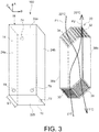
- the second cover 14 has an opening 76 (visible on the figures 2 and 3 ) for the evacuation of stale air, opening into the cavity 56.
- the opening 76 is thus located opposite the external partition 4, and a tube 86 is connected to this opening 76 through the partition 4 and the insulation layer 12 until opening into the volume 105 outside the building.
- the tube 86 is also preferably arranged orthogonally to the cover 14.
- the first cover 10 has an opening 72 for the admission of stale air opening into the second channel, at its first end near the shutter member 62.
- the opening 72 is thus located opposite the interior partition 6, and a tube 82 is connected to this opening 72 by passing through the partition 6 and the insulation layer 8 until opening into the interior volume 103 of the building.
- the tube 82 is preferably arranged orthogonally to the cover 10.
- the stale air intake opening 74 and the fresh air distribution opening 72 are thus separated from each other in the direction A of the height, which avoids a short circuit between the two F1 and F2 flows.
- the hotter stale air flow will naturally tend to borrow the tube 84 and the opening 74 located higher than the tube 82 and the opening 72, dedicated to the passage of the fresh air flow F2.
- the new air intake cavity 50 there is a fourth cavity, called the new air intake cavity 50, partially delimited by the zone 30. It is also delimited by two members 64, one extending the face 38a and the other disposed at 90 ° relative to the first, so as to connect it to the junction edge between the zones 30, 36 of the exchanger.
- This cavity 50 is therefore the only one of the four cavities which is not delimited by the peripheral faces of the housing 18, being located at a distance from the faces 24a, 22b.
- the cavity 50 is nevertheless located near a lower lateral end portion of the system 100, laterally opposite the cavity 56.
- the second cover 14 has an opening 70 (visible on the figures 2 and 3 ) for the admission of fresh air, opening into the cavity 50.
- the opening 70 is thus located opposite the external partition 4, and a tube 80 is connected to this opening 70 through the partition 4 and the insulation layer 12 until it opens into the volume 105 outside the building.
- the tube 80 is also preferably arranged orthogonally to the cover 14.
- the withdrawal of the fresh air intake cavity 50 allows the first air channel 40a to extend at the periphery of the system 100, around the exchanger 20 between the stale air intake cavity 54 and the stale air evacuation cavity 56. Indeed, starting from the controllable bypass means 60, the air channel 40a extends firstly in the direction A along the face 24a of the housing, then externally bypasses this new air intake cavity 50 along the face 22a.
- the members 64 therefore also participate in the delimitation of the first air channel 40a, which opens at its lower end into the exhaust air cavity 56.
- the figure 4 shows the exchanger system 100 according to an operating configuration in heating mode, preferably used in winter.
- the bypass means 60 are closed and prevent air communication between the stale air intake cavity 54 and the first channel 40a. Therefore, the flow of stale air F1 entering the system 100 through the tube 84 enters the cavity 54, the zone 34, the core of the exchanger 20, the zone 36, the air ejection cavity. stale 56 then the tube 86.
- the flow F1 is forced to escape from the cavity 54 by the stale air discharge opening 76, and not by the channel 40a already filled with air and closed at its opposite end.
- the fresh air flow F2 enters the system 100 through the tube 80, before penetrate into the cavity 50 and through the zone 30. It then travels through the core of the exchanger 20 to exit therefrom through the zone 32, from which it joins the cavity 52 then the second air channel 40b, before escaping through the opening 72 and the associated tube 82, in the direction of the interior space 103.
- the first air channel 40a fulfills a function of dead air volume whose temperature is in equilibrium with the peripheral environment of the exchanger system. It therefore advantageously participates in the creation of a quasi-adiabatic peripheral buffer zone, reinforcing the overall energy performance of the exchanger system. This almost adiabatic peripheral zone is observed all around the system 100, not only with the first aforementioned air channel, but also with the second air channel 40b fulfilling a similar function, and also with the air passing through the cavities. 52, 54, 56.
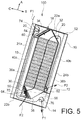
- the figure 5 shows the system 100 in another operating configuration, allowing simple ventilation, without heat exchange.
- This configuration is preferably adopted in summer, when the fresh air is cooler than the stale air.
- the bypass means 60 are controlled in the open position, so as to establish air communication between the stale air intake cavity 54 and the first channel 40a.
- the bypass means 60 can take the form of a simple shutter that can be actuated using conventional means.
- the flap is open, the flow of stale air F1 present in the stale air intake cavity 54 will naturally pass through the first air channel 40a and bypass the exchanger 20.
- the air preferably takes the air path that consumes the least energy potential, namely the path of the bypass channel 40a. From this channel, the flow of stale air F1 enters the stale air evacuation cavity 56 before being extracted from the system by the tube 86.
- the outer case 18 is equipped with another shutter member 63 extending in the direction C, and connecting the faces 24b, 38b in the upper part of the system.
- This member 63 which takes the form of a single wall, makes it possible to separate the fresh air distribution cavity 52 from a second end of the second channel 40b.
- the opening 74 for the distribution of fresh air is then made on the first cover 10 by opening into the fresh air distribution cavity 52, and no longer in the second channel 40 arranged below. The latter is thus closed at its two ends and therefore participates in the creation of a quasi-adiabatic peripheral buffer zone, reinforcing the overall energy performance of the exchanger system.
- the openings 72 and 74 remain spaced from one another in the direction B, but are located substantially at the same height in the direction A.
- diffusers can be installed with adequate orientations, for example at the level of the associated tubes 82, 84, in the interior space 103 of the building.
- a third preferred embodiment of the invention is shown, with a design close to that of the second mode.
- the main difference lies in the fact that the stale air intake cavity 54 is no longer closed by the upper edge of the exchanger 20, the latter now being at a distance and facing the face 22a, and no longer resting on it.
- the cavity 54 bypasses the aforementioned edge and continues with a channel which protects the fresh air distribution cavity 52, separated from the channel by a wall 67.
- This wall 67 therefore therefore being parallel to the face 22a between the 'aforementioned edge of the exchanger, and the face 24b on which it is connected.
- the opening 74 for the intake of stale air is located at the end of the channel extending the cavity 54, close to the face 24b, being substantially aligned in the direction A with the opening 72 for fresh air distribution.
- the proximity of the two openings 72, 74 can lead to the use of deflectors in the room, to avoid a short circuit between the stale air and the fresh air.
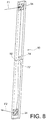
- a column or ramp 90 shown on the figures 8 , 9a and 9b can locally replace the internal partition 6, or be provided in addition to the latter. It allows the distribution and collection of air, as will be explained below.
- the column 90 has two complementary orifices 72 ′, 74 ′ communicating respectively with the openings 72, 74 of the exchanger system 100. These orifices 72 ′, 74 ′ respectively open into two compartments separated by a partition 92, allowing the segregation between flows F1 and F2. At the opposite ends of these two compartments of the column 90, namely respectively at the top and at the bottom of the part, there are two diffusers 94, 94 allowing the passage of the flows F1 and F2. These are then separated by a distance almost corresponding to a room height, thus avoiding a short circuit.
Landscapes
- Engineering & Computer Science (AREA)
- Mechanical Engineering (AREA)
- General Engineering & Computer Science (AREA)
- Physics & Mathematics (AREA)
- Thermal Sciences (AREA)
- Chemical & Material Sciences (AREA)
- Combustion & Propulsion (AREA)
- Heat-Exchange Devices With Radiators And Conduit Assemblies (AREA)
Claims (14)
- Wärmetauschersystem (100), das dazu bestimmt ist, in eine Wand (101) eines Gebäudes integriert zu werden, wobei das System ein Außengehäuse (18) und einen Doppel-Luftstrom- und Gegenstromwärmetauscher (20) enthält, der im Gehäuse aufgenommen ist, wobei der Wärmetauscher einen Frischlufteinlassbereich (30), einen Frischluftverteilungsbereich (32), einen Ablufteinlassbereich (34) und einen Abluftauslassbereich (36) enthält, wobei der Frischlufteinlassbereich und der Abluftauslassbereich sich an einem ersten Ende des Wärmetauschers (20) in einer ersten Richtung (A) des Systems befinden und dabei in einer zweiten Richtung (B) des Systems orthogonal zur ersten Richtung zueinander versetzt sind, und wobei der Ablufteinlassbereich und der Frischluftverteilungsbereich sich an einem zweiten Ende des Wärmetauschers in der ersten Richtung (A) befinden und dabei auch in der zweiten Richtung (B) zueinander versetzt sind,
wobei das Außengehäuse (18) eine erste und zweite Schließkappe (10, 14) enthält, die in einer dritten Richtung (C) des Systems entgegengesetzt liegen, wobei die dritte Richtung orthogonal zu der ersten und zweiten Richtung (A, B) verläuft,
wobei das Außengehäuse (18) einen Ablufteinlasshohlraum (54) aufweist, der teilweise durch den Ablufteinlassbereich (34) begrenzt ist, sowie einen Frischlufteinlasshohlraum (50), der teilweise durch den Frischlufteinlassbereich (30) begrenzt ist, einen Frischluftverteilungshohlraum (52), der teilweise durch den Frischluftverteilungsbereich (32) begrenzt ist, und einen Abluftauslasshohlraum (56), der teilweise durch den Abluftauslassbereich (36) begrenzt ist,
wobei die erste Schließkappe (10) eine in den Ablufteinlasshohlraum (54) mündende Öffnung (74) für den Einlass von Abluft und eine mit dem Frischluftverteilungshohlraum (52) kommunizierende Öffnung (72) für die Verteilung von Frischluft aufweist, wobei die zweite Schließkappe (14) eine in den Frischlufteinlasshohlraum (50) mündende Öffnung (70) für den Einlass von Frischluft und eine in den Abluftauslasshohlraum (56) mündende Öffnung (76) für den Auslass von Abluft aufweist,
wobei das Außengehäuse (18) an seinem Umfang einen ersten Luftkanal (40a) enthält, der sich um den Wärmetauscher (20) herum zwischen dem Ablufteinlasshohlraum (54) und dem Abluftauslasshohlraum (56) erstreckt, in welchen er hineinmündet, wobei der erste Luftkanal (40a) außen den Frischlufteinlasshohlraum (50) umgeht und von dem Ablufteinlasshohlraum (54) über steuerbare Mittel (60) zum Umleiten der in diesem Hohlraum (54) befindlichen Luft getrennt ist,
wobei das System (100) in der dritten Richtung (C) eine Dicke kleiner oder gleich 20 cm aufweist. - Wärmetauschersystem nach Anspruch 1,
dadurch gekennzeichnet, dass
das Außengehäuse (18) an seinem Umfang einen zweiten Luftkanal (40b) enthält, der sich in der ersten Richtung (A) entlang des Wärmetauschers (20) erstreckt, wobei ein Verschlussorgan (62) den Abluftauslasshohlraum (56) von einem ersten Ende des zweiten Kanals (40b) trennt. - Wärmetauschersystem nach Anspruch 2,
dadurch gekennzeichnet, dass
ein zweites Ende des zweiten Luftkanals (40b) in den Frischluftverteilungshohlraum (52) mündet, und dass
die Öffnung (72) zur Verteilung von Frischluft an der ersten Schließkappe (10) des Außengehäuses ausgeführt ist und dabei im Bereich des ersten Endes des zweiten Luftkanals (40b) ausmündet, damit die Öffnung (72) zur Frischluftverteilung und die Öffnung (74) zum Ablufteinlass in der ersten Richtung (A) voneinander beabstandet sind. - Wärmetauschersystem nach Anspruch 2,
dadurch gekennzeichnet, dass
ein weiteres Verschlussorgan (63) den Frischluftverteilungshohlraum (52) von einem zweiten Ende des zweiten Luftkanals (40b) trennt, und dass
die Öffnung (72) zur Frischluftverteilung in der ersten Schließkappe (10) des Außengehäuses ausgeführt ist und dabei in den Frischluftverteilungshohlraum (52) mündet. - Wärmetauschersystem nach einem der vorangehenden Ansprüche,
dadurch gekennzeichnet, dass
das Außengehäuse (18) insgesamt eine Rechteckquaderform aufweist. - Wärmetauschersystem nach einem der vorangehenden Ansprüche,
dadurch gekennzeichnet, dass
die erste Richtung (A) einer Höhenrichtung der Wand (101) entspricht. - Wärmetauschersystem nach einem der vorangehenden Ansprüche,
dadurch gekennzeichnet, dass
der Wärmetauscher (20) insgesamt in Form eines gleichmäßigen oder ungleichmäßigen hexagonalen Prismas vorliegt, wobei vier der sechs rechteckigen Seiten des Prismas den Frischlufteinlassbereich (30), den Frischluftverteilungsbereich (32), den Ablufteinlassbereich (34) bzw. den Abluftauslassbereich (36) bilden, und dass
der Wärmetauscher (20) vorzugsweise in dem Außengehäuse (18) so angeordnet ist, dass die beiden weiteren rechteckigen Seiten (38a, 38b) des Prismas parallel zur ersten Richtung (A) verlaufen. - Wärmetauschersystem nach einem der vorangehenden Ansprüche,
dadurch gekennzeichnet, dass
jeder aus Ablufteinlasshohlraum (54), Frischlufteinlasshohlraum (50), Frischluftverteilungshohlraum (52) und Abluftauslasshohlraum (56) sich im Wesentlich über die gesamte Dicke (E1) des Systems in der dritten Richtung (C) erstreckt und dabei von der ersten und der zweiten Schließkappe (10, 14) begrenzt wird. - Wärmetauschersystem nach einem der vorangehenden Ansprüche,
dadurch gekennzeichnet, dass
der Wärmetauscher (20) ein Enthalpietauscher ist, der einen Wärmetransfer und einen Feuchtigkeitstransfer zwischen den beiden Luftströmen ermöglicht. - Wärmetauschersystem nach einem der vorangehenden Ansprüche,
dadurch gekennzeichnet, dass
es Rohre (84, 82, 80, 86) enthält, die orthogonal zur ersten und zweiten Schließkappe (10, 14) angeordnet und an die Öffnung zum Ablufteinlass (74), an die Öffnung zur Frischluftverteilung (72), an die Öffnung zum Frischlufteinlass (70) bzw. an die Öffnung zum Abluftauslass (76) angeschlossen sind. - Wärmetauschersystem nach einem der vorangehenden Ansprüche,
dadurch gekennzeichnet, dass
der Wärmetauscher (20) ein Platten- oder Platten- und Rippentauscher ist. - Gebäudewand (101), enthaltend zumindest ein Wärmetauschersystem (100) nach einem der vorangehenden Ansprüche.
- Gebäudewand nach dem vorangehenden Anspruch,
dadurch gekennzeichnet, dass
sie eine äußere Trennwand (4) und eine innere Trennwand (6) enthält, zwischen denen ein Raum (2) definiert ist, in welchem das zumindest eine Wärmetauschersystem (100) aufgenommen ist, wobei vorzugsweise eine Wärmedämmschicht (8, 12) zwischen der inneren Trennwand (6) und der ersten Kappe (10) des Wärmetauschersystems (100) und zwischen der äußeren Trennwand (4) und der zweiten Kappe (14) dieses Systems eingefügt ist. - Gebäude (102), enthaltend zumindest eine Gebäudewand (101) nach Anspruch 12 oder Anspruch 13, wobei die Gebäudewand vorzugsweise eine Sanierungswand ist.
Applications Claiming Priority (2)
| Application Number | Priority Date | Filing Date | Title |
|---|---|---|---|
| FR1459049A FR3026476A1 (fr) | 2014-09-25 | 2014-09-25 | Systeme d'echangeur thermique a performances et compacite ameliorees |
| PCT/EP2015/071944 WO2016046303A1 (fr) | 2014-09-25 | 2015-09-24 | Systeme d'echangeur thermique a performances et compacite ameliorees |
Publications (2)
| Publication Number | Publication Date |
|---|---|
| EP3198215A1 EP3198215A1 (de) | 2017-08-02 |
| EP3198215B1 true EP3198215B1 (de) | 2019-12-25 |
Family
ID=52273245
Family Applications (1)
| Application Number | Title | Priority Date | Filing Date |
|---|---|---|---|
| EP15767166.0A Active EP3198215B1 (de) | 2014-09-25 | 2015-09-24 | Wärmetauschersystem mit verbesserter leistung und verbesserter kompaktheit |
Country Status (3)
| Country | Link |
|---|---|
| EP (1) | EP3198215B1 (de) |
| FR (1) | FR3026476A1 (de) |
| WO (1) | WO2016046303A1 (de) |
Family Cites Families (2)
| Publication number | Priority date | Publication date | Assignee | Title |
|---|---|---|---|---|
| KR100628078B1 (ko) * | 2005-02-15 | 2006-09-26 | 엘지전자 주식회사 | 환기시스템 |
| DE102011002605B4 (de) * | 2011-01-13 | 2015-06-18 | Blumartin Gmbh | Dezentrale Raumlüftungsvorrichtung mit Wärmerückgewinnung |
-
2014
- 2014-09-25 FR FR1459049A patent/FR3026476A1/fr not_active Ceased
-
2015
- 2015-09-24 WO PCT/EP2015/071944 patent/WO2016046303A1/fr not_active Ceased
- 2015-09-24 EP EP15767166.0A patent/EP3198215B1/de active Active
Non-Patent Citations (1)
| Title |
|---|
| None * |
Also Published As
| Publication number | Publication date |
|---|---|
| WO2016046303A1 (fr) | 2016-03-31 |
| FR3026476A1 (fr) | 2016-04-01 |
| EP3198215A1 (de) | 2017-08-02 |
Similar Documents
| Publication | Publication Date | Title |
|---|---|---|
| EP1965146B1 (de) | Kondensationswärmetauscher, der zwei Primärwärmetauscher und einen Sekundärwärmetauscher umfasst | |
| FR2876223A1 (fr) | Dispositif pour le refroidissement de batteries d'un vehicule a motorisation electrique et/ou hybride | |
| EP2306084B1 (de) | Vorrichtung zur Beleuchtung und/oder Signalisierung für Kraftfahrzeug | |
| FR2566881A1 (fr) | Ensemble de ventilation avec recuperation de chaleur | |
| WO2016016330A1 (fr) | Echangeur enthalpique ameliore | |
| EP2286158B1 (de) | Doppelfluss-wärmetauschervorrichtung | |
| EP2339253B1 (de) | Wohngebäude mit einem passiven Klimatisierungssystem | |
| CA2800715A1 (fr) | Echangeur thermique aeraulique | |
| EP3296678A1 (de) | Vereinfachter enthalpie-wärmetauscher | |
| FR3013823A1 (fr) | Echangeur air/air a double flux, installation de traitement d'air et methode de nettoyage d'un tel echangeur | |
| EP2672191B1 (de) | Kondenswasserbehälter und Luftaufbereitungsgerät, das mit einem solchen Behälter ausgestattet ist | |
| EP3198215B1 (de) | Wärmetauschersystem mit verbesserter leistung und verbesserter kompaktheit | |
| EP4010651B1 (de) | Verbesserter wärmespeicher | |
| EP3014661B1 (de) | Solarmodul mit vereinfachter feuchtigkeitspegelregulierung | |
| EP0102911A2 (de) | Einrichtung und Verfahren zur Wärmerekuperation für einen Feuerraum | |
| EP4030109B1 (de) | Lufterneuerungs- und -aufbereitungsgerät | |
| FR3000787A1 (fr) | Chauffe-eau thermodynamique | |
| FR2506906A1 (fr) | Dispositif de ventilation forcee de locaux | |
| FR2989981A1 (fr) | Elements de construction de batiments a basse consommation d'energie | |
| WO2011092622A2 (fr) | Module de production d'énergie mixte photovoltaïque et thermique à partir du rayonnement solaire, et installation équipée de tels modules | |
| WO2024056954A1 (fr) | Circuit échangeur de chaleur utilisant les hourdis et méthode d'installation d'un circuit climatiseur | |
| FR2884300A1 (fr) | Installation permettant de temperer l'air introduit dans les locaux | |
| FR3167196A1 (fr) | Dispositif de refroidissement ou de chauffage de l’air ambiant dans un espace intérieur, plus particulièrement dans un espace intérieur d’un bâtiment. | |
| CA2911450A1 (fr) | Methode et systeme de recuperation d`energie d`echange d`air de batiments | |
| FR3045685A1 (fr) | Element de construction alveolaire pour mur a regulation thermique |
Legal Events
| Date | Code | Title | Description |
|---|---|---|---|
| STAA | Information on the status of an ep patent application or granted ep patent |
Free format text: STATUS: THE INTERNATIONAL PUBLICATION HAS BEEN MADE |
|
| PUAI | Public reference made under article 153(3) epc to a published international application that has entered the european phase |
Free format text: ORIGINAL CODE: 0009012 |
|
| STAA | Information on the status of an ep patent application or granted ep patent |
Free format text: STATUS: REQUEST FOR EXAMINATION WAS MADE |
|
| 17P | Request for examination filed |
Effective date: 20170328 |
|
| AK | Designated contracting states |
Kind code of ref document: A1 Designated state(s): AL AT BE BG CH CY CZ DE DK EE ES FI FR GB GR HR HU IE IS IT LI LT LU LV MC MK MT NL NO PL PT RO RS SE SI SK SM TR |
|
| AX | Request for extension of the european patent |
Extension state: BA ME |
|
| DAV | Request for validation of the european patent (deleted) | ||
| DAX | Request for extension of the european patent (deleted) | ||
| GRAP | Despatch of communication of intention to grant a patent |
Free format text: ORIGINAL CODE: EPIDOSNIGR1 |
|
| STAA | Information on the status of an ep patent application or granted ep patent |
Free format text: STATUS: GRANT OF PATENT IS INTENDED |
|
| INTG | Intention to grant announced |
Effective date: 20190715 |
|
| GRAS | Grant fee paid |
Free format text: ORIGINAL CODE: EPIDOSNIGR3 |
|
| GRAA | (expected) grant |
Free format text: ORIGINAL CODE: 0009210 |
|
| STAA | Information on the status of an ep patent application or granted ep patent |
Free format text: STATUS: THE PATENT HAS BEEN GRANTED |
|
| AK | Designated contracting states |
Kind code of ref document: B1 Designated state(s): AL AT BE BG CH CY CZ DE DK EE ES FI FR GB GR HR HU IE IS IT LI LT LU LV MC MK MT NL NO PL PT RO RS SE SI SK SM TR |
|
| REG | Reference to a national code |
Ref country code: GB Ref legal event code: FG4D Free format text: NOT ENGLISH |
|
| REG | Reference to a national code |
Ref country code: CH Ref legal event code: EP |
|
| REG | Reference to a national code |
Ref country code: DE Ref legal event code: R096 Ref document number: 602015044315 Country of ref document: DE |
|
| REG | Reference to a national code |
Ref country code: AT Ref legal event code: REF Ref document number: 1217580 Country of ref document: AT Kind code of ref document: T Effective date: 20200115 |
|
| REG | Reference to a national code |
Ref country code: IE Ref legal event code: FG4D Free format text: LANGUAGE OF EP DOCUMENT: FRENCH |
|
| REG | Reference to a national code |
Ref country code: CH Ref legal event code: NV Representative=s name: BOVARD AG PATENT- UND MARKENANWAELTE, CH |
|
| REG | Reference to a national code |
Ref country code: NL Ref legal event code: MP Effective date: 20191225 |
|
| PG25 | Lapsed in a contracting state [announced via postgrant information from national office to epo] |
Ref country code: BG Free format text: LAPSE BECAUSE OF FAILURE TO SUBMIT A TRANSLATION OF THE DESCRIPTION OR TO PAY THE FEE WITHIN THE PRESCRIBED TIME-LIMIT Effective date: 20200325 Ref country code: FI Free format text: LAPSE BECAUSE OF FAILURE TO SUBMIT A TRANSLATION OF THE DESCRIPTION OR TO PAY THE FEE WITHIN THE PRESCRIBED TIME-LIMIT Effective date: 20191225 Ref country code: LV Free format text: LAPSE BECAUSE OF FAILURE TO SUBMIT A TRANSLATION OF THE DESCRIPTION OR TO PAY THE FEE WITHIN THE PRESCRIBED TIME-LIMIT Effective date: 20191225 Ref country code: SE Free format text: LAPSE BECAUSE OF FAILURE TO SUBMIT A TRANSLATION OF THE DESCRIPTION OR TO PAY THE FEE WITHIN THE PRESCRIBED TIME-LIMIT Effective date: 20191225 Ref country code: LT Free format text: LAPSE BECAUSE OF FAILURE TO SUBMIT A TRANSLATION OF THE DESCRIPTION OR TO PAY THE FEE WITHIN THE PRESCRIBED TIME-LIMIT Effective date: 20191225 Ref country code: GR Free format text: LAPSE BECAUSE OF FAILURE TO SUBMIT A TRANSLATION OF THE DESCRIPTION OR TO PAY THE FEE WITHIN THE PRESCRIBED TIME-LIMIT Effective date: 20200326 Ref country code: NO Free format text: LAPSE BECAUSE OF FAILURE TO SUBMIT A TRANSLATION OF THE DESCRIPTION OR TO PAY THE FEE WITHIN THE PRESCRIBED TIME-LIMIT Effective date: 20200325 |
|
| REG | Reference to a national code |
Ref country code: LT Ref legal event code: MG4D |
|
| PG25 | Lapsed in a contracting state [announced via postgrant information from national office to epo] |
Ref country code: HR Free format text: LAPSE BECAUSE OF FAILURE TO SUBMIT A TRANSLATION OF THE DESCRIPTION OR TO PAY THE FEE WITHIN THE PRESCRIBED TIME-LIMIT Effective date: 20191225 Ref country code: RS Free format text: LAPSE BECAUSE OF FAILURE TO SUBMIT A TRANSLATION OF THE DESCRIPTION OR TO PAY THE FEE WITHIN THE PRESCRIBED TIME-LIMIT Effective date: 20191225 |
|
| PG25 | Lapsed in a contracting state [announced via postgrant information from national office to epo] |
Ref country code: AL Free format text: LAPSE BECAUSE OF FAILURE TO SUBMIT A TRANSLATION OF THE DESCRIPTION OR TO PAY THE FEE WITHIN THE PRESCRIBED TIME-LIMIT Effective date: 20191225 |
|
| PG25 | Lapsed in a contracting state [announced via postgrant information from national office to epo] |
Ref country code: PT Free format text: LAPSE BECAUSE OF FAILURE TO SUBMIT A TRANSLATION OF THE DESCRIPTION OR TO PAY THE FEE WITHIN THE PRESCRIBED TIME-LIMIT Effective date: 20200520 Ref country code: CZ Free format text: LAPSE BECAUSE OF FAILURE TO SUBMIT A TRANSLATION OF THE DESCRIPTION OR TO PAY THE FEE WITHIN THE PRESCRIBED TIME-LIMIT Effective date: 20191225 Ref country code: NL Free format text: LAPSE BECAUSE OF FAILURE TO SUBMIT A TRANSLATION OF THE DESCRIPTION OR TO PAY THE FEE WITHIN THE PRESCRIBED TIME-LIMIT Effective date: 20191225 Ref country code: RO Free format text: LAPSE BECAUSE OF FAILURE TO SUBMIT A TRANSLATION OF THE DESCRIPTION OR TO PAY THE FEE WITHIN THE PRESCRIBED TIME-LIMIT Effective date: 20191225 Ref country code: EE Free format text: LAPSE BECAUSE OF FAILURE TO SUBMIT A TRANSLATION OF THE DESCRIPTION OR TO PAY THE FEE WITHIN THE PRESCRIBED TIME-LIMIT Effective date: 20191225 |
|
| PG25 | Lapsed in a contracting state [announced via postgrant information from national office to epo] |
Ref country code: SK Free format text: LAPSE BECAUSE OF FAILURE TO SUBMIT A TRANSLATION OF THE DESCRIPTION OR TO PAY THE FEE WITHIN THE PRESCRIBED TIME-LIMIT Effective date: 20191225 Ref country code: SM Free format text: LAPSE BECAUSE OF FAILURE TO SUBMIT A TRANSLATION OF THE DESCRIPTION OR TO PAY THE FEE WITHIN THE PRESCRIBED TIME-LIMIT Effective date: 20191225 Ref country code: IS Free format text: LAPSE BECAUSE OF FAILURE TO SUBMIT A TRANSLATION OF THE DESCRIPTION OR TO PAY THE FEE WITHIN THE PRESCRIBED TIME-LIMIT Effective date: 20200425 |
|
| REG | Reference to a national code |
Ref country code: DE Ref legal event code: R097 Ref document number: 602015044315 Country of ref document: DE |
|
| PG25 | Lapsed in a contracting state [announced via postgrant information from national office to epo] |
Ref country code: DK Free format text: LAPSE BECAUSE OF FAILURE TO SUBMIT A TRANSLATION OF THE DESCRIPTION OR TO PAY THE FEE WITHIN THE PRESCRIBED TIME-LIMIT Effective date: 20191225 Ref country code: ES Free format text: LAPSE BECAUSE OF FAILURE TO SUBMIT A TRANSLATION OF THE DESCRIPTION OR TO PAY THE FEE WITHIN THE PRESCRIBED TIME-LIMIT Effective date: 20191225 |
|
| PGFP | Annual fee paid to national office [announced via postgrant information from national office to epo] |
Ref country code: DE Payment date: 20200910 Year of fee payment: 6 Ref country code: GB Payment date: 20200921 Year of fee payment: 6 |
|
| PLBE | No opposition filed within time limit |
Free format text: ORIGINAL CODE: 0009261 |
|
| STAA | Information on the status of an ep patent application or granted ep patent |
Free format text: STATUS: NO OPPOSITION FILED WITHIN TIME LIMIT |
|
| REG | Reference to a national code |
Ref country code: AT Ref legal event code: MK05 Ref document number: 1217580 Country of ref document: AT Kind code of ref document: T Effective date: 20191225 |
|
| PG25 | Lapsed in a contracting state [announced via postgrant information from national office to epo] |
Ref country code: SI Free format text: LAPSE BECAUSE OF FAILURE TO SUBMIT A TRANSLATION OF THE DESCRIPTION OR TO PAY THE FEE WITHIN THE PRESCRIBED TIME-LIMIT Effective date: 20191225 |
|
| PGFP | Annual fee paid to national office [announced via postgrant information from national office to epo] |
Ref country code: CH Payment date: 20200923 Year of fee payment: 6 |
|
| 26N | No opposition filed |
Effective date: 20200928 |
|
| PG25 | Lapsed in a contracting state [announced via postgrant information from national office to epo] |
Ref country code: AT Free format text: LAPSE BECAUSE OF FAILURE TO SUBMIT A TRANSLATION OF THE DESCRIPTION OR TO PAY THE FEE WITHIN THE PRESCRIBED TIME-LIMIT Effective date: 20191225 Ref country code: IT Free format text: LAPSE BECAUSE OF FAILURE TO SUBMIT A TRANSLATION OF THE DESCRIPTION OR TO PAY THE FEE WITHIN THE PRESCRIBED TIME-LIMIT Effective date: 20191225 |
|
| PG25 | Lapsed in a contracting state [announced via postgrant information from national office to epo] |
Ref country code: PL Free format text: LAPSE BECAUSE OF FAILURE TO SUBMIT A TRANSLATION OF THE DESCRIPTION OR TO PAY THE FEE WITHIN THE PRESCRIBED TIME-LIMIT Effective date: 20191225 |
|
| PG25 | Lapsed in a contracting state [announced via postgrant information from national office to epo] |
Ref country code: MC Free format text: LAPSE BECAUSE OF FAILURE TO SUBMIT A TRANSLATION OF THE DESCRIPTION OR TO PAY THE FEE WITHIN THE PRESCRIBED TIME-LIMIT Effective date: 20191225 |
|
| REG | Reference to a national code |
Ref country code: BE Ref legal event code: MM Effective date: 20200930 |
|
| PG25 | Lapsed in a contracting state [announced via postgrant information from national office to epo] |
Ref country code: LU Free format text: LAPSE BECAUSE OF NON-PAYMENT OF DUE FEES Effective date: 20200924 |
|
| PG25 | Lapsed in a contracting state [announced via postgrant information from national office to epo] |
Ref country code: BE Free format text: LAPSE BECAUSE OF NON-PAYMENT OF DUE FEES Effective date: 20200930 Ref country code: IE Free format text: LAPSE BECAUSE OF NON-PAYMENT OF DUE FEES Effective date: 20200924 |
|
| PGFP | Annual fee paid to national office [announced via postgrant information from national office to epo] |
Ref country code: FR Payment date: 20210930 Year of fee payment: 7 |
|
| REG | Reference to a national code |
Ref country code: DE Ref legal event code: R119 Ref document number: 602015044315 Country of ref document: DE |
|
| REG | Reference to a national code |
Ref country code: CH Ref legal event code: PL |
|
| GBPC | Gb: european patent ceased through non-payment of renewal fee |
Effective date: 20210924 |
|
| PG25 | Lapsed in a contracting state [announced via postgrant information from national office to epo] |
Ref country code: TR Free format text: LAPSE BECAUSE OF FAILURE TO SUBMIT A TRANSLATION OF THE DESCRIPTION OR TO PAY THE FEE WITHIN THE PRESCRIBED TIME-LIMIT Effective date: 20191225 Ref country code: MT Free format text: LAPSE BECAUSE OF FAILURE TO SUBMIT A TRANSLATION OF THE DESCRIPTION OR TO PAY THE FEE WITHIN THE PRESCRIBED TIME-LIMIT Effective date: 20191225 Ref country code: CY Free format text: LAPSE BECAUSE OF FAILURE TO SUBMIT A TRANSLATION OF THE DESCRIPTION OR TO PAY THE FEE WITHIN THE PRESCRIBED TIME-LIMIT Effective date: 20191225 |
|
| PG25 | Lapsed in a contracting state [announced via postgrant information from national office to epo] |
Ref country code: MK Free format text: LAPSE BECAUSE OF FAILURE TO SUBMIT A TRANSLATION OF THE DESCRIPTION OR TO PAY THE FEE WITHIN THE PRESCRIBED TIME-LIMIT Effective date: 20191225 |
|
| PG25 | Lapsed in a contracting state [announced via postgrant information from national office to epo] |
Ref country code: GB Free format text: LAPSE BECAUSE OF NON-PAYMENT OF DUE FEES Effective date: 20210924 Ref country code: DE Free format text: LAPSE BECAUSE OF NON-PAYMENT OF DUE FEES Effective date: 20220401 |
|
| PG25 | Lapsed in a contracting state [announced via postgrant information from national office to epo] |
Ref country code: LI Free format text: LAPSE BECAUSE OF NON-PAYMENT OF DUE FEES Effective date: 20210930 Ref country code: CH Free format text: LAPSE BECAUSE OF NON-PAYMENT OF DUE FEES Effective date: 20210930 |
|
| PG25 | Lapsed in a contracting state [announced via postgrant information from national office to epo] |
Ref country code: FR Free format text: LAPSE BECAUSE OF NON-PAYMENT OF DUE FEES Effective date: 20220930 |