EP3198300B1 - Procédé permettant de faire fonctionner une pluralité de capteurs radar dans un véhicule à moteur et véhicule à moteur - Google Patents
Procédé permettant de faire fonctionner une pluralité de capteurs radar dans un véhicule à moteur et véhicule à moteur Download PDFInfo
- Publication number
- EP3198300B1 EP3198300B1 EP15770797.7A EP15770797A EP3198300B1 EP 3198300 B1 EP3198300 B1 EP 3198300B1 EP 15770797 A EP15770797 A EP 15770797A EP 3198300 B1 EP3198300 B1 EP 3198300B1
- Authority
- EP
- European Patent Office
- Prior art keywords
- radar sensors
- motor vehicle
- radar
- data
- sensors
- Prior art date
- Legal status (The legal status is an assumption and is not a legal conclusion. Google has not performed a legal analysis and makes no representation as to the accuracy of the status listed.)
- Active
Links
Images


Classifications
-
- G—PHYSICS
- G01—MEASURING; TESTING
- G01S—RADIO DIRECTION-FINDING; RADIO NAVIGATION; DETERMINING DISTANCE OR VELOCITY BY USE OF RADIO WAVES; LOCATING OR PRESENCE-DETECTING BY USE OF THE REFLECTION OR RERADIATION OF RADIO WAVES; ANALOGOUS ARRANGEMENTS USING OTHER WAVES
- G01S13/00—Systems using the reflection or reradiation of radio waves, e.g. radar systems; Analogous systems using reflection or reradiation of waves whose nature or wavelength is irrelevant or unspecified
- G01S13/88—Radar or analogous systems specially adapted for specific applications
- G01S13/93—Radar or analogous systems specially adapted for specific applications for anti-collision purposes
- G01S13/931—Radar or analogous systems specially adapted for specific applications for anti-collision purposes of land vehicles
-
- G—PHYSICS
- G01—MEASURING; TESTING
- G01S—RADIO DIRECTION-FINDING; RADIO NAVIGATION; DETERMINING DISTANCE OR VELOCITY BY USE OF RADIO WAVES; LOCATING OR PRESENCE-DETECTING BY USE OF THE REFLECTION OR RERADIATION OF RADIO WAVES; ANALOGOUS ARRANGEMENTS USING OTHER WAVES
- G01S13/00—Systems using the reflection or reradiation of radio waves, e.g. radar systems; Analogous systems using reflection or reradiation of waves whose nature or wavelength is irrelevant or unspecified
- G01S13/86—Combinations of radar systems with non-radar systems, e.g. sonar, direction finder
-
- G—PHYSICS
- G01—MEASURING; TESTING
- G01S—RADIO DIRECTION-FINDING; RADIO NAVIGATION; DETERMINING DISTANCE OR VELOCITY BY USE OF RADIO WAVES; LOCATING OR PRESENCE-DETECTING BY USE OF THE REFLECTION OR RERADIATION OF RADIO WAVES; ANALOGOUS ARRANGEMENTS USING OTHER WAVES
- G01S13/00—Systems using the reflection or reradiation of radio waves, e.g. radar systems; Analogous systems using reflection or reradiation of waves whose nature or wavelength is irrelevant or unspecified
- G01S13/88—Radar or analogous systems specially adapted for specific applications
- G01S13/93—Radar or analogous systems specially adapted for specific applications for anti-collision purposes
- G01S13/931—Radar or analogous systems specially adapted for specific applications for anti-collision purposes of land vehicles
- G01S2013/932—Radar or analogous systems specially adapted for specific applications for anti-collision purposes of land vehicles using own vehicle data, e.g. ground speed, steering wheel direction
-
- G—PHYSICS
- G01—MEASURING; TESTING
- G01S—RADIO DIRECTION-FINDING; RADIO NAVIGATION; DETERMINING DISTANCE OR VELOCITY BY USE OF RADIO WAVES; LOCATING OR PRESENCE-DETECTING BY USE OF THE REFLECTION OR RERADIATION OF RADIO WAVES; ANALOGOUS ARRANGEMENTS USING OTHER WAVES
- G01S13/00—Systems using the reflection or reradiation of radio waves, e.g. radar systems; Analogous systems using reflection or reradiation of waves whose nature or wavelength is irrelevant or unspecified
- G01S13/88—Radar or analogous systems specially adapted for specific applications
- G01S13/93—Radar or analogous systems specially adapted for specific applications for anti-collision purposes
- G01S13/931—Radar or analogous systems specially adapted for specific applications for anti-collision purposes of land vehicles
- G01S2013/9327—Sensor installation details
- G01S2013/93271—Sensor installation details in the front of the vehicles
-
- G—PHYSICS
- G01—MEASURING; TESTING
- G01S—RADIO DIRECTION-FINDING; RADIO NAVIGATION; DETERMINING DISTANCE OR VELOCITY BY USE OF RADIO WAVES; LOCATING OR PRESENCE-DETECTING BY USE OF THE REFLECTION OR RERADIATION OF RADIO WAVES; ANALOGOUS ARRANGEMENTS USING OTHER WAVES
- G01S13/00—Systems using the reflection or reradiation of radio waves, e.g. radar systems; Analogous systems using reflection or reradiation of waves whose nature or wavelength is irrelevant or unspecified
- G01S13/88—Radar or analogous systems specially adapted for specific applications
- G01S13/93—Radar or analogous systems specially adapted for specific applications for anti-collision purposes
- G01S13/931—Radar or analogous systems specially adapted for specific applications for anti-collision purposes of land vehicles
- G01S2013/9327—Sensor installation details
- G01S2013/93272—Sensor installation details in the back of the vehicles
-
- G—PHYSICS
- G01—MEASURING; TESTING
- G01S—RADIO DIRECTION-FINDING; RADIO NAVIGATION; DETERMINING DISTANCE OR VELOCITY BY USE OF RADIO WAVES; LOCATING OR PRESENCE-DETECTING BY USE OF THE REFLECTION OR RERADIATION OF RADIO WAVES; ANALOGOUS ARRANGEMENTS USING OTHER WAVES
- G01S13/00—Systems using the reflection or reradiation of radio waves, e.g. radar systems; Analogous systems using reflection or reradiation of waves whose nature or wavelength is irrelevant or unspecified
- G01S13/88—Radar or analogous systems specially adapted for specific applications
- G01S13/93—Radar or analogous systems specially adapted for specific applications for anti-collision purposes
- G01S13/931—Radar or analogous systems specially adapted for specific applications for anti-collision purposes of land vehicles
- G01S2013/9327—Sensor installation details
- G01S2013/93274—Sensor installation details on the side of the vehicles
Definitions
- the invention relates to a method for operating a plurality of radar sensors in a motor vehicle, wherein at least one operating parameter of the radar sensors can be changed, and to a motor vehicle.
- radar sensors are mostly used as environment sensors for a medium and larger distance range in order to be able to determine other road users or larger objects in terms of distance, angle and relative speed.
- Such radar data can be included in environment models or can also be made available directly to vehicle systems.
- longitudinal guidance systems such as ACC or also safety systems make use of radar data.
- Radar sensors of conventional design usually have a larger dimension and are rather bulky, since the antennas and the electronic components required directly on the antenna, i.e. the radar front end, are integrated in a housing.
- the electronic components mainly form the radar transceiver, which contains a frequency control (usually comprising a phase-locked loop - PLL), mixing devices, a low noise amplifier (LNA) and the like, but often control modules and digital signal processing components are also implemented close to the antenna, for example by already processed
- a frequency control usually comprising a phase-locked loop - PLL
- mixing devices usually comprising a phase-locked loop - PLL
- LNA low noise amplifier
- control modules and digital signal processing components are also implemented close to the antenna, for example by already processed
- sensor data for example object lists
- a connected bus for example a CAN bus.
- CMOS complementary metal-oxide-semiconductor
- an extremely cost-effective small radar sensor is possible, which can meet installation space requirements significantly better and, due to the short signal paths, also has a very low signal-to-noise ratio and for high frequencies and larger, variable frequency bandwidths is suitable. Therefore, such small radar sensors can also be used for short-range applications, for example in the range from 30 cm to 10 m.
- CMOS transceiver chip and / or a package with a CMOS transceiver chip and antenna on a common printed circuit board with a digital signal processor (DSP processor) or to integrate the functions of the signal processor into the CMOS Integrate transceiver chip.
- DSP processor digital signal processor
- radar sensors are usually operated as “stand-alone” sensors, which means that each radar sensor decides for itself under which operating parameters it should work and deliver Radar data, whereby radar sensors have already been proposed in which signal and function algorithms are implemented.
- the radar sensors themselves also form the control devices and can thus, for example, directly control various actuators and / or make outputs, for example via a human-machine interface of the motor vehicle.
- the monitored area to be recorded is defined by the implemented or addressed function.
- the radar sensors are permanently programmed for a special function that can be assigned to a vehicle system, for example. This limits the use of the radar sensors for other functions, and the radar sensors are always active, which means a high energy requirement.
- DE 198 45 568 A1 relates to a device for object detection for motor vehicles, comprising a distance sensor system formed by a plurality of distance sensors, which are arranged on a motor vehicle in such a way that they scan the surroundings of the motor vehicle, and an evaluation unit, which uses the data from the distance sensor system to determine the trajectory and speed of a Object determined relative to the motor vehicle.
- the distance sensors can optionally be controlled by the evaluation unit and the range and / or the measurement repetition frequency and / or the resolution and / or the operating mode of the distance sensors can be changed.
- U.S. 5,717,399 A discloses a radar device for use in a vehicle.
- a radar module for detecting objects in the short range comprising a plurality of short-range antennas and a transmitting / receiving device
- a monitoring module for detecting distant objects comprising a plurality of long-range antennas and a transmitting / receiving device
- the radar device has a control device that can change a resolution mode or the operating time ratio of the radar module.
- EP 2 439 714 A1 relates to a vehicle environment monitoring device and a corresponding monitoring method.
- a radar control system provided with a central control unit which controls several radar sensors arranged around the vehicle.
- US 2014/0191895 A1 relates to a radar system for vehicles, with a specific arrangement of the at least two radar sensors to be used for environmental monitoring.
- the radar sensors are activated by a control unit with regard to their visibility.
- US 2012/0194377 A1 relates to an antenna device with two differently oriented antennas, a radar device using such an antenna device, and a vehicle radar system.
- a vehicle radar system can comprise two radar devices, one of which can be designed as a master and the other as a slave.
- the invention is therefore based on the object of improving the operation of radar sensors in motor vehicles in terms of efficiency and availability for different functions of vehicle systems.
- the invention therefore proposes a centralized control of the radar sensors, which uses driving situation data about the current driving situation to determine which properties the currently required sensor data of the radar sensors should have in order to be as beneficial as possible through at least one function of the vehicle systems of the motor vehicle, preferably several functions of the vehicle systems of the motor vehicle to be processed.
- This is defined by a requirement profile for the sensor data.
- a requirements profile can contain, for example, from which environmental areas of interest sensor data are required, how often / quickly these sensor data are required and in what quality the sensor data are required.
- the device executing the method according to the invention knows where the radar sensors are arranged and what properties the radar sensors have, it is possible to map this requirement profile, knowing the detection properties of the radar sensors, to operating parameters of the radar sensors that meet the requirement profile as well as possible.
- a holistic view of the performance of all radar sensors is therefore carried out in order to be able to meet the requirement profile as precisely as possible and also to achieve improvements in terms of energy requirements, bus utilization and / or computing resource requirements, after a decision can be made, for example, which radar sensors are currently not needed and which radar sensors are required. If a suitable architecture is chosen for the radar sensors themselves or if the radar sensors are even connected to a central unit, many applications, specifically functions of vehicle systems, can benefit from the performance of this configuration optimization. Additional information about the driving situation is therefore used in order to determine the most efficient possible operation of the totality of the radar sensors, taking into account the interaction, addition and the like of the detection properties of all radar sensors.
- the requirement profile can be described, for example, by requirement parameters, which preferably specify for different areas of the surroundings of the motor vehicle the priority with which data are required from there (or whether data from there are required at all), what the desired accuracy of the sensor data from the area is as well as how fast and / or with what frequency data should ideally be obtained. If the driving situation data shows, for example, that a turning maneuver is currently taking place, ultimately only sensor data from the direction in which the motor vehicle is turning is relevant, for example radar sensors that are aligned to the left in a left-turning maneuver. The other radar sensors can be deactivated, for example.
- a critical area of the surroundings can be defined, for example, which contains this potential collision partner and from which extremely precise radar data can be obtained extremely quickly. For example, data acquisition rates or accuracies of others Radar sensors are reduced in order to enable rapid transport and rapid evaluation of these sensor data from the critical surrounding area.
- the evaluation of the requirement profile and, ideally, additional efficiency criteria result in operating strategies that are perfectly coordinated between the radar sensors.
- radar sensors which include a semiconductor chip that realizes the radar transceiver, in particular a CMOS chip.
- the novel radar sensors described at the beginning, especially implemented in CMOS technology not only offer the advantage of being able to be implemented in an extremely compact manner and thus, for example, to be built into doors, bumpers and the like, but it is also possible, especially if through the semiconductor chip a digital signal processing component and / or a control unit of the radar sensor can also be implemented to provide part of the intelligence in these radar sensors and, in particular, to enable fast and efficient change of operating parameters in the radar sensor.
- a particularly compact, highly integrated design results when the semiconductor chip and an antenna arrangement of the radar sensor are implemented as a package. The radar sensor can then be made extremely small, for example by the package arranged on a circuit board.
- an activation and / or deactivation of a radar sensor can be triggered by the operating parameters and / or a data acquisition rate and / or at least one operating parameter describing the detection area and / or an operating parameter describing the distance separation capability and / or an operating parameter can be used as operating parameters Radar sensor to be made preliminary evaluation of descriptive operating parameters are used. It is therefore conceivable, on the one hand, to switch a radar sensor on or off temporarily by means of a corresponding operating parameter, but it is also possible that as an operating parameter Generally speaking, the current detection properties changing operating parameters are used.
- the detection properties of the radar sensors taken into account in the implementation of the requirement profile are therefore to be understood to include the basic setting options of the radar sensors and their effects on the current detection properties.
- the general detection properties of the radar sensors with regard to the operating parameters therefore indicate the basic options for setting to a specific operating state with certain current detection properties, but also contain the arrangement of the radar sensor and allow conclusions to be drawn about the detected part of the vehicle's surroundings.
- a specific advantageous embodiment of the present invention provides that, in a surrounding area of interest described by the requirement profile, only the radar sensors detecting the surrounding area of interest or the radar sensors detecting the surrounding area of interest are operated with more frequent and / or more accurate sensor data than the other operating parameters delivering radar sensors. Furthermore, as already described, it is conceivable that at least two radar sensors are operated for the redundant detection of at least part of the critical environmental area in a critical environmental area described by the requirement profile, in particular as a sub-area of the environmental area of interest. This is explained in more detail using a few specific examples.
- At least one radar sensor with a higher frequency bandwidth, for example 3 GHz, while the remaining radar sensors are operated with a low bandwidth, for example 100 MHz. It is also possible to operate some radar sensors with a higher cycle time (lower data acquisition rate) and others with a lower cycle time (higher data acquisition rate).
- the detection quality can be increased, for example by reducing ambiguities, if several neighboring radar sensors, whose detection areas overlap in overlapping areas, can redundantly detect certain objects. If the object is contained in the sensor data of all these radar sensors, the sensor data can be statistically combined with respect to the object.
- the radar system formed by the radar sensors is operated as sparingly as possible with regard to energy consumption, the bus bandwidth used, the computing resources and the like, whereby of course requirement profiles, for example with regard to potential collision effects or other possibly risky driving maneuvers, generally outweigh these efficiency criteria.
- the question evaluated in the operating method according to the invention is how the requirement profile can be achieved with otherwise the highest possible efficiency.
- one of the radar sensors is switched off and / or its detection area is adapted to minimize redundancy in the case of a non-critical portion of a surrounding area of interest contained in the requirement profile redundantly detecting radar sensors. So it is too It is entirely possible, if an increase in the detection quality is not desired, to switch off radar sensors that deliver the same measurements from the identical object. This saves energy and computing resources and reduces the amount of data in the bus system. Of course, this also applies to radar sensors that are not relevant to the current traffic scenario.
- radar sensors that detect the surroundings of the motor vehicle in a 360 ° angle range are used in their detection areas.
- Several radar sensors can therefore be used in the motor vehicle in such a way that 360 ° monitoring of the entire surroundings of the motor vehicle is made possible, which also enables more precise mapping of the entire surroundings (static and dynamic) to be achieved.
- Such an arrangement of radar sensors can be achieved, for example, with eight radar sensors if radar sensors arranged in each case in the corner areas of the motor vehicle and between the corners of the motor vehicle are used.
- the radar sensors provided at the corners of the motor vehicle can be oriented, for example, at a 45 ° angle to the longitudinal direction of the motor vehicle, and the radar sensors disposed between the corners can each be oriented perpendicular to the side in which they are disposed.
- a central control unit of the motor vehicle which in particular is assigned to at least two vehicle systems.
- Such central control devices are known, for example, under the catchphrase "central driver assistance system” (zFAS).
- zFAS central driver assistance system
- the idea is that all the functions to be carried out by driver assistance systems are implemented on a single control device which also receives the sensor data from all connected sensors, including the radar sensors.
- control unit also determines and updates an environment model of the motor vehicle, since the driving situation data can then also include data from the environment model which is already present in the control unit.
- a central control unit usually receives further driving situation data describing the current operating state and the driving situation anyway, so that when all the necessary input data are available, the requirement profile and the operating parameters can be determined particularly easily as an additional function.
- Different connection architectures of the radar sensors with the central control unit are conceivable, for example a separate connection (star architecture) for each radar sensor, or the use of rings or chains along which the radar sensors are connected.
- star architecture star architecture
- the evaluation of the driving situation and the activation of the radar sensors are carried out by a computing device of at least one of the radar sensors. Since modern radar sensors themselves have a certain intelligence, for example in the case of the described radar sensors implemented in semiconductor technology, which implement a control unit and / or digital signal processing components through the semiconductor chip, the function described by the method according to the invention for determining the requirement profile and the operating parameters can therefore be used without any problems can also be implemented within a radar sensor.
- the radar sensor whose computing device takes over this central coordination, ultimately has a master role, while the remaining radar sensors can be regarded as slaves.
- the master radar sensor uses appropriate algorithms, which can be part of a decision module, for example, in order to evaluate the driving situation data for the requirement profile and to derive suitable operating parameters from this. It is also conceivable that such a master radar sensor acts as a distribution point for the sensor data from the radar sensors, for example initially receiving all sensor data from all radar sensors and forwards them or even realizing functions of at least one vehicle system that evaluates the sensor data.
- the radar sensor is selected dynamically as a function of the driving situation data and / or the operating parameters.
- Each radar sensor can therefore basically be configured as a master or slave, even while driving, for example depending on the current traffic scenario, i.e. the current driving situation. This enables particularly efficient use (distribution of intelligence) of the configuration with multiple radar sensors.
- data transmission paths from the other radar sensors and the like that supply the most relevant sensor data can be taken into account, for example.
- the most varied of input data describing the driving situation can be used as driving situation data.
- ego data describing the operating state of the motor vehicle and / or at least one predictive operating state of the motor vehicle and / or environment data describing the environment of the motor vehicle and / or request data describing specific requirements from at least one vehicle system are used as driving situation data.
- This information gives an overall picture of the driving situation from which the requirement profile, for example as a requirement parameter, can be derived. If request data from vehicle systems or also individual functions of vehicle systems are used, prioritization can be provided within the vehicle systems and / or functions so that, for example, safety-relevant vehicle systems are prioritized higher than comfort-relevant vehicle systems and the like.
- control device is preferably a central control device that realizes the functions of a plurality of vehicle systems and, if necessary, also determines and updates an environment model of the motor vehicle.
- the radar sensors can preferably include a semiconductor chip, in particular a CMOS chip, realizing the radar transceiver. It is particularly expedient in this context if the semiconductor chip also implements a digital signal processing component and / or a control unit of the radar sensor and / or the semiconductor chip and an antenna arrangement of the radar sensor are implemented as a package. As already stated, such radar sensors can be implemented in an extremely compact manner and, in particular when using CMOS technology, are inexpensive to manufacture and are therefore available. In this way, even larger numbers of radar sensors can be integrated into various components of the motor vehicle, for example in a vehicle door and / or a bumper, in a space-saving manner and ideally invisible from the outside.
- the radar sensors also have a corresponding intelligence for performing functions, in particular also for the method according to the invention, so that it can be provided that the computing device for performing the method according to the invention, the digital signal processing component and / or the control unit of a radar sensor can be used.
- Fig. 1 shows a schematic diagram of a motor vehicle 1 of a first embodiment not according to the invention.
- it has eight radar sensors 2a - 2h, with four radar sensors 2a, 2c, 2e, 2g being arranged at the corners of the motor vehicle 1, the remaining radar sensors 2b, 2d, 2f and 2h on the sides in the middle between the corner radar sensors 2a, 2c, 2e and 2g.
- the associated largest possible detection areas of the radar sensors 2a - 2h are shown in Fig. 2 and designated by the reference numerals 3a-3h. Obviously, a 360 ° angle range is covered.
- the radar sensors 2a, 2c, 2d, 2e, 2g and 2h can be arranged in the bumpers of the motor vehicle 1, the radar sensors 2b and 2f in the doors.
- Various operating parameters of the radar sensors 2a-2h can be set, in particular operating parameters defining the current detection properties such as opening angle, bandwidth, data acquisition rate and the like.
- a central control device 4 is provided to control the operation of the radar sensors 2a-2h.
- the radar sensors 2a - 2h are each connected to the control device 4 in four pieces via a chain, although other connection architectures are also conceivable.
- the central control unit 4 executes various functions of several driver assistance systems, in particular all driver assistance systems, and uses sensor data from the radar sensors 2a - 2h and other sensors of the motor vehicle 1, which are not shown here, to determine and update an environment model of the motor vehicle 1, which is generated by the various functions is taken into account.
- ego data of the motor vehicle are made available to the central control device 4 via further vehicle systems not shown in detail here, which can describe the current operating state of the motor vehicle 1 and possibly predicted future operating states. It is therefore possible within the control device 4 to create a good image of the current driving situation of the motor vehicle 1 using the available driving situation data and possibly further data of the functions.
- a requirement profile for the sensor data of the radar sensors 2a-2h is determined from current driving situation data that describe the driving situation of the motor vehicle 1.
- driving situation data for example, environment data describing the environment of the motor vehicle, for example the described environment model, and ego data of the motor vehicle 1, for example its speed, steering angle and the like, are taken into account. It is expedient to also take into account request data of the functions that use the sensor data of the radar sensors 2a-2h, it being possible for the functions or the corresponding vehicle systems to be prioritized among one another.
- a requirements profile is obtained in step S1, which can be described, for example, by requirement parameters.
- a requirements profile of this type can first specify the area of interest of the surroundings of the motor vehicle 1 from which sensor data are to be obtained.
- This surrounding area of interest can now be subdivided into parts to which, for example, priorities and / or attributes are assigned. For example, if a potential collision object has been detected in a critical surrounding area as a sub-area of the surrounding area of interest, cf. in Fig. 2 For example, the object 5, this critical surrounding area can be given a high priority and / or particularly precise sensor data can be requested particularly quickly from this area.
- Other interesting and / or even critical environmental areas arise, for example, from the current direction of travel of the motor vehicle 1.
- the environmental area behind the motor vehicle 1 is the relevant environmental area; if there is a turning process to the right, the surrounding area lying to the right of motor vehicle 1 is the surrounding area of interest and the like. Obviously, it can be inferred from the driving situation from where, with what frequency, speed and quality, sensor data of the radar sensors 2a-2h are required, which is described by the requirement profile.
- a step S2 operating parameters are now determined from this requirement profile, taking into account efficiency criteria 6, with which this requirement profile can (best) be realized. These operating parameters can also include an operating parameter that controls activation and deactivation of the respective radar sensor 2a-2h.
- Efficiency criteria 6 relate in particular to the energy consumption, the restriction of the data traffic on the bus systems of the motor vehicle 1 and the lowest possible utilization of computing resources. If, for example, there is a right-turn process, no or only very little data is required from the radar sensors 2e, 2f and 2g pointing to the left, so that these can be deactivated, for example, which saves energy and data traffic as well as computing resources.
- the Sensors 2h and 2d which are directed forwards and backwards, respectively, supply data that could be relevant, but not as relevant as the sensor data supplied, for example, by sensors 2a and 2b, so that the detection ranges of sensors 2a and 2b ideally can be adjusted so that they reflect the most important environmental area and a particularly high data acquisition rate is given with high accuracy, while the sensors 2h and 2d can be operated with below-average data acquisition rates and rather lower quality requirements, while the sensor 2c can continue to be operated with medium operating parameters.
- the detection areas of sensors 3a, 3b and 3h can be set so that all three radar sensors 3a, 3b and 3h detect the object 5, so that redundant detection is given and more precise information about the object 5 can be obtained. It is also conceivable, however, that there is no critical driving situation and consequently, based on the efficiency criteria, 6 objects should only be recorded once.
- the current, actually used detection areas of the sensors 3a, 3b and 3h can be adapted in such a case that only one of these radar sensors 3a, 3b and 3h, for example the radar sensor 3a, actually measures the object 5.
- a large number of driving situations can be mapped to corresponding requirement profiles, from which in turn an optimally suitable set of operating parameters for the radar sensors 2a - 2h follows, which meet this requirement profile as efficiently as possible, for example by switching off / activating some sensors , be operated with higher or lower resource requirements and the like.
- step S3 the radar sensors 2a-2h are activated in accordance with the operating parameters determined in step S2.
- the dashed arrow 7 in Fig. 3 indicates, the method is of course repeated cyclically, so that the current driving situation is always mapped by corresponding operating parameter sets, with a holistic consideration of the radar systems formed by the radar sensors 2a - 2h in order to optimally meet requirement profiles.
- Fig. 4 shows a particularly advantageously usable radar sensor 2 in more detail.
- This comprises a circuit board 8, on which a package 9 is arranged, which is formed from the antenna arrangement 10 of the radar sensor 2 and a semiconductor chip 11, here a CMOS chip.
- a radar transceiver 12, a control unit 13 and a digital signal processing component 14 (DSP) are implemented by the CMOS chip 11.
- the radar sensor 2 can be made extremely compact and can therefore be installed in doors and bumpers of the motor vehicle 1 in a space-saving manner.
- the components implemented by the semiconductor chip 11 already provide a certain intelligence on the radar sensor side.
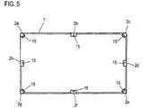
- each of the sensors 2a - 2h now has a computing device 15 which is designed to carry out the method according to the invention, which in the present case is formed by the control unit 13 and / or the digital signal processing component 14.
- One of the sensors 2a - 2h is now determined as the master, in particular depending on the driving situation, and its computing device 15 executes the method according to the invention until another sensor 2a - 2h is determined as the master.
- the other sensors 2a - 2h which are not the master, ultimately act as slaves. In this way, the distributed intelligence that is given in the radar sensors 2a-2h can be used particularly expediently.
Landscapes
- Engineering & Computer Science (AREA)
- Radar, Positioning & Navigation (AREA)
- Remote Sensing (AREA)
- Physics & Mathematics (AREA)
- Computer Networks & Wireless Communication (AREA)
- General Physics & Mathematics (AREA)
- Electromagnetism (AREA)
- Radar Systems Or Details Thereof (AREA)
- Traffic Control Systems (AREA)
Claims (11)
- Procédé pour faire fonctionner une pluralité de capteurs radar (2, 2a-2h) dans un véhicule automobile (1, 1'), dans lequel des capteurs radar (2, 2a-2h) saisissant l'environnement du véhicule automobile (1, 1') dans une portée angulaire de 360° sont utilisés dans leurs portées de saisie (3a-3h), et au moins un paramètre de fonctionnement des capteurs radar (2, 2a-2h) peut être modifié, dans lequel les données de situation de conduite décrivant une situation de conduite réelle du véhicule automobile (1, 1') sont évaluées pour déterminer un profil d'exigences pour les données des capteurs radar (2, 2a-2h) et les paramètres de fonctionnement des capteurs radar (2, 2a-2h) sont adaptés au profil d'exigences en tenant compte au moins des caractéristiques de saisie de tous les capteurs radar (2, 2a-2h),
caractérisé en ce que
chacun des capteurs radar (2, 2a-2h) présente un appareil de calcul (15) et l'évaluation de la situation de conduite et l'activation des capteurs radar (2, 2a-2h) par l'appareil de calcul (15) d'au moins un des capteurs radar (2, 2a-2h) a lieu, dans lequel le capteur radar (2, 2a-2h) dont l'appareil de calcul (15) est utilisé, est sélectionné de manière dynamique en fonction des données de la situation de conduite et/ou des paramètres de fonctionnement. - Procédé selon la revendication 1,
caractérisé en ce que
une activation et/ou une désactivation d'un capteur radar (2, 2a-2h) est déclenchée par les paramètres de fonctionnement et/ou, en tant que paramètre de fonctionnement, un taux d'acquisition des données et/ou au moins un paramètre de fonctionnement décrivant la portée de saisie (3a-3h) et/ou au moins un paramètre de fonctionnement décrivant la capacité de séparation de distance et/ou au moins un paramètre de fonctionnement décrivant la pré-évaluation à devant être effectuée par le capteur radar (2, 2a-2h) sont utilisés. - Procédé selon la revendication 1 ou 2,
caractérisé en ce que
dans le cas d'une portée d'environnement d'intérêt décrite par le profil de demande, seulement les capteurs radar (2, 2a-2h) saisissant la portée d'environnement d'intérêt ou les capteurs radar (2, 2a-2h) saisissant la portée d'environnement d'intérêt avec des données de capteur plus fréquentes et/ou plus précises que les autres capteurs radar (2, 2a-2h) sont mis en fonctionnement. - Procédé selon l'une quelconque des revendications précédentes,
caractérisé en ce que
dans le cas d'une portée d'environnement critique décrite par le profil d'exigences, en particulier comme une sous-portée de la portée d'environnement d'intérêt, au moins deux capteurs radar (2, 2a-2h) sont exploités pour la saisie redondante d'au moins une partie de la portée d'environnement critique. - Procédé selon l'une quelconque des revendications précédentes,
caractérisé en ce que
lors de l'adaptation des paramètres de fonctionnement des capteurs radar (2, 2a-2h), également au moins un critère d'efficacité minimisant la consommation d'énergie et/ou la quantité de données à transporter et/ou les ressources informatiques nécessaires (6) est pris en compte. - Procédé selon la revendication 5,
caractérisé en ce que
dans le cas d'une partie non critique d'une portée d'environnement d'intérêt contenue dans le profil d'exigences saisissant de manière redondante des capteurs radar (2, 2a-2h), l'un des capteurs radar (2, 2a-2h) est désactivé et/ou sa portée de saisie (3a-3h) est adaptée pour minimiser la redondance. - Procédé selon l'une quelconque des revendications précédentes,
caractérisé en ce que
un parmi huit capteurs radar (2, 2a-2h) est agencé respectivement dans les portées de coins du véhicule automobile (1, 1') et entre les angles du véhicule automobile (1,1'). - Procédé selon l'une quelconque des revendications précédentes,
caractérisé en ce que
les données sur l'ego décrivant l'état de fonctionnement du véhicule automobile (1, 1') et/ou au moins un état de fonctionnement prédictif du véhicule automobile (1, 1') et/ou les données sur l'environnement décrivant l'environnement du véhicule automobile (1,1') et/ou les données sur les exigences décrivant les exigences spécifiques d'au moins un système du véhicule sont utilisées comme données sur la situation de conduite. - Véhicule automobile (1, 1') avec plusieurs capteurs radar (2, 2a-2h) qui, dans leurs portées de saisie (3 bis-h), saisissent l'environnement du véhicule automobile (1, 1') dans une portée angulaire de 360° et présentent chacun un appareil de calcul (15) ;
dans lequel les appareils de calcul (15) des capteurs radar (2, 2a-2h) et un équipement de commande (4) du véhicule automobile (1, 1') sont réalisés pour effectuer un procédé selon l'une quelconque des revendications précédentes. - Véhicule automobile selon la revendication 9,
caractérisé en ce que
les capteurs radar (2, 2a-2h) comprennent une puce semi-conductrice (11) réalisant l'émetteur-récepteur radar (12), en particulier une puce CMOS. - Véhicule automobile selon la revendication 10,
caractérisé en ce que
également un composant de traitement de signal (14) numérique et/ou une unité de commande (12) du capteur radar (2, 2a-2h) sont réalisés et/ou la puce semi-conductrice (11) et un agencement d'antenne (10) du capteur radar (2, 2a-2h) sont réalisés par la puce semi-conductrice (11) comme un ensemble (9).
Applications Claiming Priority (2)
| Application Number | Priority Date | Filing Date | Title |
|---|---|---|---|
| DE102014014307.4A DE102014014307A1 (de) | 2014-09-25 | 2014-09-25 | Verfahren zum Betrieb einer Mehrzahl von Radarsensoren in einem Kraftfahrzeug und Kraftfahrzeug |
| PCT/EP2015/001892 WO2016045794A1 (fr) | 2014-09-25 | 2015-09-24 | Procédé permettant de faire fonctionner une pluralité de capteurs radar dans un véhicule à moteur et véhicule à moteur |
Publications (2)
| Publication Number | Publication Date |
|---|---|
| EP3198300A1 EP3198300A1 (fr) | 2017-08-02 |
| EP3198300B1 true EP3198300B1 (fr) | 2020-08-26 |
Family
ID=54199161
Family Applications (1)
| Application Number | Title | Priority Date | Filing Date |
|---|---|---|---|
| EP15770797.7A Active EP3198300B1 (fr) | 2014-09-25 | 2015-09-24 | Procédé permettant de faire fonctionner une pluralité de capteurs radar dans un véhicule à moteur et véhicule à moteur |
Country Status (5)
| Country | Link |
|---|---|
| US (2) | US10451729B2 (fr) |
| EP (1) | EP3198300B1 (fr) |
| CN (1) | CN106716173B (fr) |
| DE (1) | DE102014014307A1 (fr) |
| WO (1) | WO2016045794A1 (fr) |
Families Citing this family (34)
| Publication number | Priority date | Publication date | Assignee | Title |
|---|---|---|---|---|
| DE102014014307A1 (de) | 2014-09-25 | 2016-03-31 | Audi Ag | Verfahren zum Betrieb einer Mehrzahl von Radarsensoren in einem Kraftfahrzeug und Kraftfahrzeug |
| DE102015011927B3 (de) * | 2015-09-12 | 2016-12-15 | Audi Ag | Verfahren zur Reduzierung des Energieverbrauchs von Radarsensoren in einem Kraftfahrzeug und Kraftfahrzeug |
| DE102016202112A1 (de) * | 2016-02-12 | 2017-08-17 | Robert Bosch Gmbh | Radarsensor für Fahrerassistenzsysteme in Kraftfahrzeugen |
| DE102016004305A1 (de) * | 2016-04-08 | 2017-10-12 | Audi Ag | Kraftfahrzeug mit mehreren an unterschiedlichen Einbaupositionen angeordneten Radarsensoren und Verfahren zum Betreiben mehrerer an unterschiedlichen Einbaupositionen eines Kraftfahrzeugs angeordneter Radarsensoren |
| DE102016210365A1 (de) * | 2016-06-10 | 2017-12-14 | Audi Ag | Verfahren zum Betrieb eines Fahrzeugsystems zum Wegrollschutz und Kraftfahrzeug |
| DE102016222549B4 (de) * | 2016-11-16 | 2019-05-16 | Audi Ag | Verfahren zum Ermitteln einer Anhängerinformation und Kraftfahrzeug |
| DE102017205495A1 (de) * | 2017-03-31 | 2018-10-04 | Conti Temic Microelectronic Gmbh | Vorrichtung und Verfahren zum Fokussieren von Sensoren im fahrdynamischen Grenzbereich für ein Kraftfahrzeug |
| US10386856B2 (en) * | 2017-06-29 | 2019-08-20 | Uber Technologies, Inc. | Autonomous vehicle collision mitigation systems and methods |
| CN110998692B (zh) * | 2017-08-03 | 2024-03-08 | 株式会社小糸制作所 | 车辆系统以及车辆 |
| US10551493B2 (en) | 2017-08-18 | 2020-02-04 | GM Global Technology Operations LLC | Widely spaced radar nodes with unambiguous beam pattern |
| DE102017214657B3 (de) | 2017-08-22 | 2018-11-22 | Audi Ag | Verfahren zur Auswertung von Radardaten und Kraftfahrzeug |
| JPWO2019058720A1 (ja) * | 2017-09-22 | 2020-11-19 | ソニー株式会社 | 情報処理装置、自律型移動装置、および方法、並びにプログラム |
| DE102017217805B4 (de) | 2017-10-06 | 2019-05-02 | Vega Grieshaber Kg | Radarfüllstandmessgerät mit Synchronisationssignal auf verschiedenen Leitungstypen |
| CN108279671B (zh) * | 2018-01-08 | 2021-12-14 | 深圳市易成自动驾驶技术有限公司 | 基于太赫兹的环境感知方法、装置及计算机可读存储介质 |
| DE102018200814B3 (de) * | 2018-01-18 | 2019-07-18 | Audi Ag | Verfahren zum Betrieb eines zur vollständig automatischen Führung eines Kraftfahrzeugs ausgebildeten Fahrzeugführungssystems des Kraftfahrzeugs und Kraftfahrzeug |
| DE102018202296A1 (de) * | 2018-02-15 | 2019-08-22 | Robert Bosch Gmbh | Radarsensor-System und Verfahren zum Betreiben eines Radarsensor-Systems |
| JP7045249B2 (ja) * | 2018-04-19 | 2022-03-31 | 本田技研工業株式会社 | 輸送機器 |
| DE102018206553A1 (de) * | 2018-04-27 | 2019-10-31 | Robert Bosch Gmbh | Radarsensorkopf für ein Radarsystem |
| CN110418310B (zh) * | 2018-04-28 | 2021-03-30 | 华为技术有限公司 | 车辆雷达通信一体化的实现方法、相关设备及系统 |
| US11353872B2 (en) * | 2018-07-30 | 2022-06-07 | Pony Ai Inc. | Systems and methods for selectively capturing and filtering sensor data of an autonomous vehicle |
| US20210373151A1 (en) * | 2018-10-12 | 2021-12-02 | Kyocera Corporation | Electronic device, control method of electronic device, and control program of electronic device |
| DE102018219376A1 (de) * | 2018-11-13 | 2020-05-14 | Robert Bosch Gmbh | Verfahren zum Auswählen und beschleunigten Ausführen von Handlungsreaktionen |
| DE102018130916A1 (de) * | 2018-12-05 | 2020-06-10 | Valeo Schalter Und Sensoren Gmbh | Verfahren zum priorisierten Übertragen von erfassten Informationen eines Sensors eines Kraftfahrzeugs an eine Steuereinheit des Kraftfahrzeugs, Sensor, Fahrerassistenzsystem sowie Kraftfahrzeug |
| DE102019203783B4 (de) * | 2019-03-20 | 2022-08-11 | Vitesco Technologies GmbH | Verfahren, Programm und System zur Verwendung von Signalqualitätsanforderungen im Rahmen von Sicherheitskonzepten |
| DE102019203808A1 (de) * | 2019-03-20 | 2020-09-24 | Robert Bosch Gmbh | Verfahren und Datenverarbeitungsvorrichtung zum Analysieren einer Sensorverbundkonfiguration und zumindest teilautonomer Roboter |
| CN115616952A (zh) | 2019-06-21 | 2023-01-17 | 华为技术有限公司 | 传感器的控制方法、装置和传感器 |
| JP7310524B2 (ja) * | 2019-10-11 | 2023-07-19 | トヨタ自動車株式会社 | 遠隔自動運転車両、及び車両遠隔指示システム |
| EP3869221B1 (fr) | 2020-02-20 | 2025-12-31 | Magna Electronics Sweden AB | Système radar comportant des sous-bandes |
| EP4113166A4 (fr) * | 2020-02-25 | 2024-03-20 | Furukawa Electric Co. Ltd. | Dispositif de traitement, procédé de traitement et programme de traitement |
| EP4143600A1 (fr) * | 2020-04-28 | 2023-03-08 | Veoneer Sweden AB | Test d'émetteur-récepteur radar |
| CN113954766B (zh) * | 2020-07-20 | 2026-02-10 | 罗伯特·博世有限公司 | 用于基于状况地处理机动车的传感器数据的方法和装置 |
| DE102022001262A1 (de) * | 2022-04-12 | 2023-10-12 | Mercedes-Benz Group AG | Innenraumüberwachungssystem und Verfahren zu dessen Betrieb sowie Fahrzeug mit einem solchen Innenraumüberwachungssystem |
| DE102023200606A1 (de) * | 2023-01-26 | 2024-08-01 | Volkswagen Aktiengesellschaft | Radarsystem mit CMOS-Elektronikkomponenten |
| WO2025153865A1 (fr) * | 2024-01-17 | 2025-07-24 | ロベルト•ボッシュ•ゲゼルシャフト•ミト•ベシュレンクテル•ハフツング | Appareil de traitement et procédé de traitement pour acquérir une position d'un terminal mobile par rapport à un véhicule |
Citations (1)
| Publication number | Priority date | Publication date | Assignee | Title |
|---|---|---|---|---|
| US20120194377A1 (en) * | 2011-01-31 | 2012-08-02 | Denso Corporation | Antenna apparatus, radar apparatus and on-vehicle radar system |
Family Cites Families (51)
| Publication number | Priority date | Publication date | Assignee | Title |
|---|---|---|---|---|
| JP3302848B2 (ja) * | 1994-11-17 | 2002-07-15 | 本田技研工業株式会社 | 車載レーダー装置 |
| DE19529173C1 (de) * | 1995-08-08 | 1997-01-09 | Siemens Ag | Radargerät mit reduzierter abgestrahlter Leistung |
| US5847661A (en) * | 1996-03-15 | 1998-12-08 | Intelligent Ideation, Inc. | Vehicle data acquisition system |
| GB9613645D0 (en) * | 1996-06-28 | 1996-08-28 | Cambridge Consultants | Vehicle radar system |
| DE19803660C2 (de) | 1998-01-30 | 2001-07-05 | Siemens Ag | Kraftfahrzeugradar |
| JP3463734B2 (ja) * | 1998-03-30 | 2003-11-05 | 三菱電機株式会社 | 気象観測レーダシステム |
| DE19845568A1 (de) | 1998-04-23 | 1999-10-28 | Volkswagen Ag | Vorrichtung zur Objekterfassung für Kraftfahrzeuge |
| US6268803B1 (en) * | 1998-08-06 | 2001-07-31 | Altra Technologies Incorporated | System and method of avoiding collisions |
| KR100803414B1 (ko) * | 2000-08-16 | 2008-02-13 | 레이던 컴퍼니 | 근거리 물체 감지 시스템 |
| DE10059673A1 (de) * | 2000-12-01 | 2002-06-06 | Bosch Gmbh Robert | Impuls-Radarverfahren sowie Impuls-Radarsensor und System |
| JP3885716B2 (ja) * | 2002-11-21 | 2007-02-28 | 日産自動車株式会社 | 車両用推奨操作量生成装置 |
| KR100498965B1 (ko) * | 2003-04-22 | 2005-07-01 | 삼성전자주식회사 | 차량간 임시 무선 네트워크를 이용한 차량 운행정보 교환방법 및 시스템 |
| JP4544305B2 (ja) * | 2005-05-13 | 2010-09-15 | 株式会社村田製作所 | レーダ |
| JPWO2006123499A1 (ja) * | 2005-05-16 | 2008-12-25 | 株式会社村田製作所 | レーダ |
| JP2007116217A (ja) * | 2005-10-18 | 2007-05-10 | Hitachi Ltd | ミリ波レーダ装置およびそれを用いたミリ波レーダシステム |
| JP4224096B2 (ja) * | 2006-10-27 | 2009-02-12 | 三菱電機株式会社 | レーダ装置 |
| EP2084555A2 (fr) * | 2006-10-31 | 2009-08-05 | Valeo Raytheon Systems, Inc. | Système et procédé pour un créer un signal d'alerte dans un système de détection |
| JP5160114B2 (ja) * | 2007-03-26 | 2013-03-13 | 本田技研工業株式会社 | 車両の通り抜け判断装置 |
| JP4476315B2 (ja) * | 2007-08-17 | 2010-06-09 | 三菱電機株式会社 | 車載レーダ装置 |
| US20090254260A1 (en) * | 2008-04-07 | 2009-10-08 | Axel Nix | Full speed range adaptive cruise control system |
| US7969349B2 (en) * | 2009-04-06 | 2011-06-28 | Raytheon Company | System and method for suppressing close clutter in a radar system |
| JP2010261784A (ja) * | 2009-05-01 | 2010-11-18 | Denso Corp | レーダ装置 |
| JP5327321B2 (ja) * | 2009-06-04 | 2013-10-30 | トヨタ自動車株式会社 | 車両用周辺監視装置及び車両用周辺監視方法 |
| US8354920B2 (en) * | 2010-01-22 | 2013-01-15 | John Kole | Vehicle overhead clearance detection system and method of operation |
| US8600606B2 (en) * | 2010-02-11 | 2013-12-03 | GM Global Technology Operations LLC | Vehicle safety systems and methods |
| JP5183661B2 (ja) * | 2010-03-29 | 2013-04-17 | 三菱電機株式会社 | 車載レーダ装置 |
| CN101833092B (zh) | 2010-04-27 | 2012-07-04 | 成都捌零科技有限公司 | 车辆360度障碍无死角智能检测与预警方法 |
| EP2390679B1 (fr) * | 2010-05-27 | 2012-10-03 | Mitsubishi Electric R&D Centre Europe B.V. | Radar d'automobile doté d'évitement d'interférence de fréquence radio |
| DE102011078641A1 (de) * | 2011-07-05 | 2013-01-10 | Robert Bosch Gmbh | Radarsystem für Kraftfahrzeuge sowie Kraftfahrzeug mit einem Radarsystem |
| EP2743721B1 (fr) * | 2011-08-12 | 2019-10-02 | Panasonic Corporation | Appareil radar |
| JP5866917B2 (ja) * | 2011-09-20 | 2016-02-24 | 富士通株式会社 | 探知測距装置および探知測距方法 |
| DE102011055693A1 (de) * | 2011-11-24 | 2013-05-29 | Hella Kgaa Hueck & Co. | Radargerät und Verfahren zur Erkennung eines Ausfalls eines Empfangskanals eines Radargerätes |
| US8957807B2 (en) * | 2011-12-14 | 2015-02-17 | Ford Global Technologies, Llc | Internal multi-axis G sensing used to align an automotive forward radar to the vehicle's thrust axis |
| US20130169468A1 (en) * | 2011-12-30 | 2013-07-04 | Flir Systems, Inc. | Radar system and related methods |
| DE102013101079A1 (de) * | 2012-02-03 | 2013-08-08 | Conti Temic Microelectronic Gmbh | Verfahren und Vorrichtung zur Priorisierung von Prozessen |
| DE102012015250A1 (de) | 2012-08-01 | 2014-02-06 | Audi Ag | Radarsensor für ein Kraftfahrzeug, Kraftfahrzeug und Kommunikationsverfahren |
| JP5324690B1 (ja) * | 2012-09-21 | 2013-10-23 | 株式会社小松製作所 | 作業車両用周辺監視システム及び作業車両 |
| US8994581B1 (en) * | 2012-09-25 | 2015-03-31 | Adam Brown | Direction of arrival (DOA) estimation using multiple offset receive channels |
| US9116242B2 (en) * | 2013-03-06 | 2015-08-25 | Toyota Motor Engineering & Manufacturing North America, Inc. | Map aware adaptive automotive radar |
| JP6304257B2 (ja) * | 2013-09-12 | 2018-04-04 | パナソニック株式会社 | レーダ装置、車両及び移動体速度検出方法 |
| JP6413240B2 (ja) | 2014-01-08 | 2018-10-31 | 株式会社デンソー | 車両制御装置および車両 |
| DE102014201026A1 (de) * | 2014-01-21 | 2015-07-23 | Robert Bosch Gmbh | Verfahren zur Winkelschätzung und Radarsensor für Kraftfahrzeuge |
| JP6371534B2 (ja) * | 2014-02-12 | 2018-08-08 | 株式会社デンソーテン | レーダ装置、車両制御システム、および、信号処理方法 |
| US9733348B2 (en) * | 2014-07-03 | 2017-08-15 | GM Global Technology Operations LLC | Vehicle radar with beam adjustment |
| TWI571399B (zh) * | 2014-08-20 | 2017-02-21 | 啟碁科技股份有限公司 | 預警方法及車用雷達系統 |
| US9720072B2 (en) * | 2014-08-28 | 2017-08-01 | Waymo Llc | Methods and systems for vehicle radar coordination and interference reduction |
| DE102014014307A1 (de) | 2014-09-25 | 2016-03-31 | Audi Ag | Verfahren zum Betrieb einer Mehrzahl von Radarsensoren in einem Kraftfahrzeug und Kraftfahrzeug |
| US10006987B2 (en) * | 2014-10-08 | 2018-06-26 | Nxp Usa, Inc. | Radar device utilizing phase shift |
| US9541638B2 (en) * | 2014-11-11 | 2017-01-10 | Nxp B.V. | MIMO radar system |
| US9720080B1 (en) * | 2014-11-25 | 2017-08-01 | Sandia Corporation | Combined radar and telemetry system |
| JP2016118427A (ja) * | 2014-12-19 | 2016-06-30 | 富士通テン株式会社 | レーダ装置、および、信号処理方法 |
-
2014
- 2014-09-25 DE DE102014014307.4A patent/DE102014014307A1/de not_active Withdrawn
-
2015
- 2015-09-24 EP EP15770797.7A patent/EP3198300B1/fr active Active
- 2015-09-24 WO PCT/EP2015/001892 patent/WO2016045794A1/fr not_active Ceased
- 2015-09-24 US US15/514,459 patent/US10451729B2/en active Active
- 2015-09-24 CN CN201580051669.6A patent/CN106716173B/zh not_active Expired - Fee Related
-
2019
- 2019-10-22 US US16/660,674 patent/US10877149B2/en active Active
Patent Citations (1)
| Publication number | Priority date | Publication date | Assignee | Title |
|---|---|---|---|---|
| US20120194377A1 (en) * | 2011-01-31 | 2012-08-02 | Denso Corporation | Antenna apparatus, radar apparatus and on-vehicle radar system |
Also Published As
| Publication number | Publication date |
|---|---|
| EP3198300A1 (fr) | 2017-08-02 |
| CN106716173A (zh) | 2017-05-24 |
| DE102014014307A1 (de) | 2016-03-31 |
| US20170285165A1 (en) | 2017-10-05 |
| CN106716173B (zh) | 2020-07-07 |
| US10877149B2 (en) | 2020-12-29 |
| US10451729B2 (en) | 2019-10-22 |
| US20200124720A1 (en) | 2020-04-23 |
| WO2016045794A1 (fr) | 2016-03-31 |
Similar Documents
| Publication | Publication Date | Title |
|---|---|---|
| EP3198300A1 (fr) | Procédé permettant de faire fonctionner une pluralité de capteurs radar dans un véhicule à moteur et véhicule à moteur | |
| EP3397990B1 (fr) | Procédé d'opérer un système d'assistance au conducteur d'un véhicule et véhicule | |
| DE102017216435B4 (de) | Verfahren zum Betrieb von Radarsensoren und Kraftfahrzeug | |
| DE102015200020B4 (de) | Fahrzeugsteuervorrichtung, Fahrzeug und Fahrzeugsteuerverfahren | |
| DE102019201141A1 (de) | Adaptiver Geschwindigkeitsregler in einem Motorrad zur Zielverfolgung | |
| EP3151035B1 (fr) | Procede de fonctionnement de capteurs radars dans un vehicule automobile et vehicule automobile | |
| EP3141433B1 (fr) | Procédé de fonctionnement d'un système d'assistance du conducteur pour l'assistance d'au moins une personne hors du véhicule | |
| DE102011012379B4 (de) | Verfahren und Radar-Sensoranordnung zur Detektion von Ort und Geschwindigkeit von Objekten relativ zu einem Fahrzeug | |
| DE102010055993A1 (de) | Integrierte Radarvorrichtung und integrierte Antennenvorrichtung | |
| DE102017124868A1 (de) | Verbesserte Objekterfassung in mehreren Radaren | |
| EP3452847B1 (fr) | Véhicule automobile comprenant au moins deux capteurs radars | |
| DE102014009869A1 (de) | Verfahren zum Betrieb eines Radarsensors in einem Kraftfahrzeug und Kraftfahrzeug | |
| EP2244104A2 (fr) | Procédé et dispositif de fonctionnement d'un système de reconnaissance de l'environnement assisté par radar | |
| DE102017124863A1 (de) | Fahrzeugradarsteuerung | |
| EP2065727B1 (fr) | Procédé d'évaluation de la largeur d'objets radar | |
| DE102018122595A1 (de) | Synchronisation mehrerer radaranlaufzeiten zur störungsminderung | |
| EP2966725A1 (fr) | Radome pour un dispositif de capteur radar ayant au moins deux capteurs radar et dispositif de capteur radar | |
| DE102014009861A1 (de) | Radarsensorvorrichtung mit wenigstens zwei Radarsensoren und Kraftfahrzeug | |
| DE102018127782A1 (de) | System und Verfahren zur Pseudozufalls-Chirp-Planung zur Vermeidung von Interferenzen | |
| DE102017201551B4 (de) | Verfahren zum Betrieb von zwei ein Gespann bildenden Kraftfahrzeugen während eines Abschleppvorgangs und Kraftfahrzeug | |
| DE102018118238A1 (de) | Verfahren zum Betreiben einer Radarvorrichtung und Radarvorrichtung | |
| DE102016004305A1 (de) | Kraftfahrzeug mit mehreren an unterschiedlichen Einbaupositionen angeordneten Radarsensoren und Verfahren zum Betreiben mehrerer an unterschiedlichen Einbaupositionen eines Kraftfahrzeugs angeordneter Radarsensoren | |
| DE102016223259A1 (de) | Verfahren zum Betrieb einer Radarsensoranordnung eines Kraftfahrzeugs und Kraftfahrzeug | |
| EP3109663A1 (fr) | Procédé destiné au fonctionnement d'un système d'assistance du conducteur d'un véhicule automobile et véhicule automobile | |
| EP3059607B1 (fr) | Procede de fonctionnement d'un systeme d'information du conducteur dans un vehicule automobile et vehicule automobile |
Legal Events
| Date | Code | Title | Description |
|---|---|---|---|
| STAA | Information on the status of an ep patent application or granted ep patent |
Free format text: STATUS: THE INTERNATIONAL PUBLICATION HAS BEEN MADE |
|
| PUAI | Public reference made under article 153(3) epc to a published international application that has entered the european phase |
Free format text: ORIGINAL CODE: 0009012 |
|
| STAA | Information on the status of an ep patent application or granted ep patent |
Free format text: STATUS: REQUEST FOR EXAMINATION WAS MADE |
|
| 17P | Request for examination filed |
Effective date: 20170425 |
|
| AK | Designated contracting states |
Kind code of ref document: A1 Designated state(s): AL AT BE BG CH CY CZ DE DK EE ES FI FR GB GR HR HU IE IS IT LI LT LU LV MC MK MT NL NO PL PT RO RS SE SI SK SM TR |
|
| AX | Request for extension of the european patent |
Extension state: BA ME |
|
| DAV | Request for validation of the european patent (deleted) | ||
| DAX | Request for extension of the european patent (deleted) | ||
| STAA | Information on the status of an ep patent application or granted ep patent |
Free format text: STATUS: EXAMINATION IS IN PROGRESS |
|
| 17Q | First examination report despatched |
Effective date: 20181129 |
|
| REG | Reference to a national code |
Ref country code: DE Ref legal event code: R079 Ref document number: 502015013340 Country of ref document: DE Free format text: PREVIOUS MAIN CLASS: G01S0013870000 Ipc: G01S0013860000 |
|
| GRAP | Despatch of communication of intention to grant a patent |
Free format text: ORIGINAL CODE: EPIDOSNIGR1 |
|
| STAA | Information on the status of an ep patent application or granted ep patent |
Free format text: STATUS: GRANT OF PATENT IS INTENDED |
|
| RIC1 | Information provided on ipc code assigned before grant |
Ipc: G01S 13/931 20200101ALI20200507BHEP Ipc: G01S 13/86 20060101AFI20200507BHEP |
|
| INTG | Intention to grant announced |
Effective date: 20200602 |
|
| GRAS | Grant fee paid |
Free format text: ORIGINAL CODE: EPIDOSNIGR3 |
|
| GRAA | (expected) grant |
Free format text: ORIGINAL CODE: 0009210 |
|
| STAA | Information on the status of an ep patent application or granted ep patent |
Free format text: STATUS: THE PATENT HAS BEEN GRANTED |
|
| AK | Designated contracting states |
Kind code of ref document: B1 Designated state(s): AL AT BE BG CH CY CZ DE DK EE ES FI FR GB GR HR HU IE IS IT LI LT LU LV MC MK MT NL NO PL PT RO RS SE SI SK SM TR |
|
| REG | Reference to a national code |
Ref country code: GB Ref legal event code: FG4D Free format text: NOT ENGLISH |
|
| REG | Reference to a national code |
Ref country code: CH Ref legal event code: EP |
|
| REG | Reference to a national code |
Ref country code: AT Ref legal event code: REF Ref document number: 1306885 Country of ref document: AT Kind code of ref document: T Effective date: 20200915 |
|
| REG | Reference to a national code |
Ref country code: IE Ref legal event code: FG4D Free format text: LANGUAGE OF EP DOCUMENT: GERMAN |
|
| REG | Reference to a national code |
Ref country code: DE Ref legal event code: R096 Ref document number: 502015013340 Country of ref document: DE |
|
| REG | Reference to a national code |
Ref country code: LT Ref legal event code: MG4D |
|
| PG25 | Lapsed in a contracting state [announced via postgrant information from national office to epo] |
Ref country code: HR Free format text: LAPSE BECAUSE OF FAILURE TO SUBMIT A TRANSLATION OF THE DESCRIPTION OR TO PAY THE FEE WITHIN THE PRESCRIBED TIME-LIMIT Effective date: 20200826 Ref country code: SE Free format text: LAPSE BECAUSE OF FAILURE TO SUBMIT A TRANSLATION OF THE DESCRIPTION OR TO PAY THE FEE WITHIN THE PRESCRIBED TIME-LIMIT Effective date: 20200826 Ref country code: GR Free format text: LAPSE BECAUSE OF FAILURE TO SUBMIT A TRANSLATION OF THE DESCRIPTION OR TO PAY THE FEE WITHIN THE PRESCRIBED TIME-LIMIT Effective date: 20201127 Ref country code: FI Free format text: LAPSE BECAUSE OF FAILURE TO SUBMIT A TRANSLATION OF THE DESCRIPTION OR TO PAY THE FEE WITHIN THE PRESCRIBED TIME-LIMIT Effective date: 20200826 Ref country code: PT Free format text: LAPSE BECAUSE OF FAILURE TO SUBMIT A TRANSLATION OF THE DESCRIPTION OR TO PAY THE FEE WITHIN THE PRESCRIBED TIME-LIMIT Effective date: 20201228 Ref country code: NO Free format text: LAPSE BECAUSE OF FAILURE TO SUBMIT A TRANSLATION OF THE DESCRIPTION OR TO PAY THE FEE WITHIN THE PRESCRIBED TIME-LIMIT Effective date: 20201126 Ref country code: BG Free format text: LAPSE BECAUSE OF FAILURE TO SUBMIT A TRANSLATION OF THE DESCRIPTION OR TO PAY THE FEE WITHIN THE PRESCRIBED TIME-LIMIT Effective date: 20201126 Ref country code: LT Free format text: LAPSE BECAUSE OF FAILURE TO SUBMIT A TRANSLATION OF THE DESCRIPTION OR TO PAY THE FEE WITHIN THE PRESCRIBED TIME-LIMIT Effective date: 20200826 |
|
| REG | Reference to a national code |
Ref country code: NL Ref legal event code: MP Effective date: 20200826 |
|
| PG25 | Lapsed in a contracting state [announced via postgrant information from national office to epo] |
Ref country code: PL Free format text: LAPSE BECAUSE OF FAILURE TO SUBMIT A TRANSLATION OF THE DESCRIPTION OR TO PAY THE FEE WITHIN THE PRESCRIBED TIME-LIMIT Effective date: 20200826 Ref country code: NL Free format text: LAPSE BECAUSE OF FAILURE TO SUBMIT A TRANSLATION OF THE DESCRIPTION OR TO PAY THE FEE WITHIN THE PRESCRIBED TIME-LIMIT Effective date: 20200826 Ref country code: LV Free format text: LAPSE BECAUSE OF FAILURE TO SUBMIT A TRANSLATION OF THE DESCRIPTION OR TO PAY THE FEE WITHIN THE PRESCRIBED TIME-LIMIT Effective date: 20200826 Ref country code: RS Free format text: LAPSE BECAUSE OF FAILURE TO SUBMIT A TRANSLATION OF THE DESCRIPTION OR TO PAY THE FEE WITHIN THE PRESCRIBED TIME-LIMIT Effective date: 20200826 Ref country code: IS Free format text: LAPSE BECAUSE OF FAILURE TO SUBMIT A TRANSLATION OF THE DESCRIPTION OR TO PAY THE FEE WITHIN THE PRESCRIBED TIME-LIMIT Effective date: 20201226 |
|
| PG25 | Lapsed in a contracting state [announced via postgrant information from national office to epo] |
Ref country code: SM Free format text: LAPSE BECAUSE OF FAILURE TO SUBMIT A TRANSLATION OF THE DESCRIPTION OR TO PAY THE FEE WITHIN THE PRESCRIBED TIME-LIMIT Effective date: 20200826 Ref country code: RO Free format text: LAPSE BECAUSE OF FAILURE TO SUBMIT A TRANSLATION OF THE DESCRIPTION OR TO PAY THE FEE WITHIN THE PRESCRIBED TIME-LIMIT Effective date: 20200826 Ref country code: EE Free format text: LAPSE BECAUSE OF FAILURE TO SUBMIT A TRANSLATION OF THE DESCRIPTION OR TO PAY THE FEE WITHIN THE PRESCRIBED TIME-LIMIT Effective date: 20200826 Ref country code: DK Free format text: LAPSE BECAUSE OF FAILURE TO SUBMIT A TRANSLATION OF THE DESCRIPTION OR TO PAY THE FEE WITHIN THE PRESCRIBED TIME-LIMIT Effective date: 20200826 Ref country code: CZ Free format text: LAPSE BECAUSE OF FAILURE TO SUBMIT A TRANSLATION OF THE DESCRIPTION OR TO PAY THE FEE WITHIN THE PRESCRIBED TIME-LIMIT Effective date: 20200826 |
|
| REG | Reference to a national code |
Ref country code: CH Ref legal event code: PL |
|
| REG | Reference to a national code |
Ref country code: DE Ref legal event code: R097 Ref document number: 502015013340 Country of ref document: DE |
|
| PG25 | Lapsed in a contracting state [announced via postgrant information from national office to epo] |
Ref country code: ES Free format text: LAPSE BECAUSE OF FAILURE TO SUBMIT A TRANSLATION OF THE DESCRIPTION OR TO PAY THE FEE WITHIN THE PRESCRIBED TIME-LIMIT Effective date: 20200826 Ref country code: AL Free format text: LAPSE BECAUSE OF FAILURE TO SUBMIT A TRANSLATION OF THE DESCRIPTION OR TO PAY THE FEE WITHIN THE PRESCRIBED TIME-LIMIT Effective date: 20200826 Ref country code: MC Free format text: LAPSE BECAUSE OF FAILURE TO SUBMIT A TRANSLATION OF THE DESCRIPTION OR TO PAY THE FEE WITHIN THE PRESCRIBED TIME-LIMIT Effective date: 20200826 |
|
| REG | Reference to a national code |
Ref country code: BE Ref legal event code: MM Effective date: 20200930 |
|
| PG25 | Lapsed in a contracting state [announced via postgrant information from national office to epo] |
Ref country code: SK Free format text: LAPSE BECAUSE OF FAILURE TO SUBMIT A TRANSLATION OF THE DESCRIPTION OR TO PAY THE FEE WITHIN THE PRESCRIBED TIME-LIMIT Effective date: 20200826 Ref country code: LU Free format text: LAPSE BECAUSE OF NON-PAYMENT OF DUE FEES Effective date: 20200924 |
|
| PLBE | No opposition filed within time limit |
Free format text: ORIGINAL CODE: 0009261 |
|
| STAA | Information on the status of an ep patent application or granted ep patent |
Free format text: STATUS: NO OPPOSITION FILED WITHIN TIME LIMIT |
|
| PG25 | Lapsed in a contracting state [announced via postgrant information from national office to epo] |
Ref country code: IT Free format text: LAPSE BECAUSE OF FAILURE TO SUBMIT A TRANSLATION OF THE DESCRIPTION OR TO PAY THE FEE WITHIN THE PRESCRIBED TIME-LIMIT Effective date: 20200826 |
|
| 26N | No opposition filed |
Effective date: 20210527 |
|
| PG25 | Lapsed in a contracting state [announced via postgrant information from national office to epo] |
Ref country code: CH Free format text: LAPSE BECAUSE OF NON-PAYMENT OF DUE FEES Effective date: 20200930 Ref country code: BE Free format text: LAPSE BECAUSE OF NON-PAYMENT OF DUE FEES Effective date: 20200930 Ref country code: SI Free format text: LAPSE BECAUSE OF FAILURE TO SUBMIT A TRANSLATION OF THE DESCRIPTION OR TO PAY THE FEE WITHIN THE PRESCRIBED TIME-LIMIT Effective date: 20200826 Ref country code: IE Free format text: LAPSE BECAUSE OF NON-PAYMENT OF DUE FEES Effective date: 20200924 Ref country code: LI Free format text: LAPSE BECAUSE OF NON-PAYMENT OF DUE FEES Effective date: 20200930 |
|
| REG | Reference to a national code |
Ref country code: AT Ref legal event code: MM01 Ref document number: 1306885 Country of ref document: AT Kind code of ref document: T Effective date: 20200924 |
|
| PG25 | Lapsed in a contracting state [announced via postgrant information from national office to epo] |
Ref country code: AT Free format text: LAPSE BECAUSE OF NON-PAYMENT OF DUE FEES Effective date: 20200924 |
|
| PG25 | Lapsed in a contracting state [announced via postgrant information from national office to epo] |
Ref country code: TR Free format text: LAPSE BECAUSE OF FAILURE TO SUBMIT A TRANSLATION OF THE DESCRIPTION OR TO PAY THE FEE WITHIN THE PRESCRIBED TIME-LIMIT Effective date: 20200826 Ref country code: MT Free format text: LAPSE BECAUSE OF FAILURE TO SUBMIT A TRANSLATION OF THE DESCRIPTION OR TO PAY THE FEE WITHIN THE PRESCRIBED TIME-LIMIT Effective date: 20200826 Ref country code: CY Free format text: LAPSE BECAUSE OF FAILURE TO SUBMIT A TRANSLATION OF THE DESCRIPTION OR TO PAY THE FEE WITHIN THE PRESCRIBED TIME-LIMIT Effective date: 20200826 |
|
| PG25 | Lapsed in a contracting state [announced via postgrant information from national office to epo] |
Ref country code: MK Free format text: LAPSE BECAUSE OF FAILURE TO SUBMIT A TRANSLATION OF THE DESCRIPTION OR TO PAY THE FEE WITHIN THE PRESCRIBED TIME-LIMIT Effective date: 20200826 |
|
| P01 | Opt-out of the competence of the unified patent court (upc) registered |
Effective date: 20230530 |
|
| PGFP | Annual fee paid to national office [announced via postgrant information from national office to epo] |
Ref country code: GB Payment date: 20230920 Year of fee payment: 9 |
|
| PGFP | Annual fee paid to national office [announced via postgrant information from national office to epo] |
Ref country code: FR Payment date: 20230922 Year of fee payment: 9 Ref country code: DE Payment date: 20230930 Year of fee payment: 9 |
|
| REG | Reference to a national code |
Ref country code: DE Ref legal event code: R119 Ref document number: 502015013340 Country of ref document: DE |
|
| GBPC | Gb: european patent ceased through non-payment of renewal fee |
Effective date: 20240924 |
|
| PG25 | Lapsed in a contracting state [announced via postgrant information from national office to epo] |
Ref country code: DE Free format text: LAPSE BECAUSE OF NON-PAYMENT OF DUE FEES Effective date: 20250401 |
|
| PG25 | Lapsed in a contracting state [announced via postgrant information from national office to epo] |
Ref country code: GB Free format text: LAPSE BECAUSE OF NON-PAYMENT OF DUE FEES Effective date: 20240924 |
|
| PG25 | Lapsed in a contracting state [announced via postgrant information from national office to epo] |
Ref country code: FR Free format text: LAPSE BECAUSE OF NON-PAYMENT OF DUE FEES Effective date: 20240930 |