EP3198323B2 - Device for imaging a sample - Google Patents
Device for imaging a sample Download PDFInfo
- Publication number
- EP3198323B2 EP3198323B2 EP15756911.2A EP15756911A EP3198323B2 EP 3198323 B2 EP3198323 B2 EP 3198323B2 EP 15756911 A EP15756911 A EP 15756911A EP 3198323 B2 EP3198323 B2 EP 3198323B2
- Authority
- EP
- European Patent Office
- Prior art keywords
- optical
- intermediate image
- plane
- image plane
- detection
- Prior art date
- Legal status (The legal status is an assumption and is not a legal conclusion. Google has not performed a legal analysis and makes no representation as to the accuracy of the status listed.)
- Active
Links
Images



Classifications
-
- G—PHYSICS
- G02—OPTICS
- G02B—OPTICAL ELEMENTS, SYSTEMS OR APPARATUS
- G02B21/00—Microscopes
- G02B21/0004—Microscopes specially adapted for specific applications
- G02B21/002—Scanning microscopes
- G02B21/0024—Confocal scanning microscopes (CSOMs) or confocal "macroscopes"; Accessories which are not restricted to use with CSOMs, e.g. sample holders
- G02B21/0052—Optical details of the image generation
- G02B21/0076—Optical details of the image generation arrangements using fluorescence or luminescence
-
- G—PHYSICS
- G02—OPTICS
- G02B—OPTICAL ELEMENTS, SYSTEMS OR APPARATUS
- G02B21/00—Microscopes
- G02B21/0004—Microscopes specially adapted for specific applications
- G02B21/002—Scanning microscopes
- G02B21/0024—Confocal scanning microscopes (CSOMs) or confocal "macroscopes"; Accessories which are not restricted to use with CSOMs, e.g. sample holders
- G02B21/0052—Optical details of the image generation
-
- G—PHYSICS
- G02—OPTICS
- G02B—OPTICAL ELEMENTS, SYSTEMS OR APPARATUS
- G02B21/00—Microscopes
- G02B21/06—Means for illuminating specimens
-
- G—PHYSICS
- G02—OPTICS
- G02B—OPTICAL ELEMENTS, SYSTEMS OR APPARATUS
- G02B21/00—Microscopes
- G02B21/06—Means for illuminating specimens
- G02B21/08—Condensers
- G02B21/082—Condensers for incident illumination only
-
- G—PHYSICS
- G02—OPTICS
- G02B—OPTICAL ELEMENTS, SYSTEMS OR APPARATUS
- G02B21/00—Microscopes
- G02B21/36—Microscopes arranged for photographic purposes or projection purposes or digital imaging or video purposes including associated control and data processing arrangements
- G02B21/361—Optical details, e.g. image relay to the camera or image sensor
-
- G—PHYSICS
- G02—OPTICS
- G02B—OPTICAL ELEMENTS, SYSTEMS OR APPARATUS
- G02B21/00—Microscopes
- G02B21/36—Microscopes arranged for photographic purposes or projection purposes or digital imaging or video purposes including associated control and data processing arrangements
- G02B21/365—Control or image processing arrangements for digital or video microscopes
Definitions
- the invention relates to a device for imaging a sample arranged in an object plane.
- This device includes an optical transmission system which images a region of the sample from the object plane into an intermediate image plane.
- the object plane and the intermediate image plane enclose an angle different from 90° with an optical axis of the transmission system, the optical transmission system is made up of several lenses.
- the device also includes an optical imaging system with a lens whose optical axis is perpendicular to the intermediate image plane and which is focused on the intermediate image plane, so that the object plane can be imaged undistorted on a detector.
- the device also includes an illumination device for illuminating the sample with a light sheet, with illumination light being coupled into the beam path of the transmission system in the intermediate image plane or in a pupil plane and directed onto the sample by the transmission system, or being radiated directly into the object plane via a separate illumination beam path .
- the light sheet lies essentially in the object plane and determines the direction of the illumination.
- the normal of the object plane - which also corresponds to the normal of the light sheet - defines a detection direction.
- the optical transmission system consists of several lenses. It can be constructed symmetrically, so that the imaging through the optical transmission system takes place with a scale of 1:1. However, this is not absolutely necessary, the image can also be enlarged or reduced.
- Such a device is used in particular when examining biological samples, in which the sample is illuminated with a light sheet whose plane intersects the optical axis of the detection at an angle other than zero. Usually, the light sheet encloses a right angle with the detection direction.
- SPIM Selective Plane Illumination Microscopy
- spatial recordings can also be made of thicker samples in a relatively short time.
- optical sections combined with a relative movement in a direction perpendicular to the plane of the section, a pictorial, spatially extended representation of the sample is possible.
- the SPIM technique is preferably used in fluorescence microscopy, where it is also referred to as LSFM ( Light Sheet Fluorescence Microscopy ).
- LSFM Light Sheet Fluorescence Microscopy
- detection can take place in the wide field, larger sample areas can be recorded.
- the light exposure of the samples is the lowest with this method, which, among other things, reduces the risk of fading of a sample, since the sample is only illuminated by a thin sheet of light at a non-zero angle to the detection direction.
- a quasi-static light sheet can also be used. This is generated by quickly scanning the sample with a light beam.
- the light sheet-like illumination occurs when the light beam is subjected to a very rapid relative movement to the sample to be observed and is lined up several times in succession.
- the integration time of the camera on whose sensor the sample is imaged is sensibly chosen so that the scanning is completed within the integration time.
- the illumination takes place via a lens system which lies in the plane of the sample which is illuminated. If, for example, observation is made from above, the lighting must come from the side. Conventional preparation techniques can therefore not be used.
- a further major disadvantage is that both the illumination lens and the observation lens have to be arranged spatially close to one another, so that a lens with a high numerical aperture can be used for detection, which lens captures light from a wide area. At the same time, however, a light sheet must also be generated.
- SPIM optics were developed, using the same objective for illumination with a light sheet and simultaneous detection of fluorescence coming from the sample.
- the sample is illuminated with a light sheet over a partial area of the objective, which includes an edge area of this objective, so that the illumination therefore takes place at an angle that is oblique to the optical axis of the objective.
- An opposite edge area of the lens is then used for the detection, so that the detection also takes place on average at an angle that is different from zero to the optical axis of the lens. Due to the limited numerical aperture of the lens, this angle is usually less than the 90° that is otherwise used in classic SPIM technology is common.
- the imaging system is supplemented there by a transmission system, which consists of the mirror-symmetrical coupling of two imaging subsystems.
- the two imaging systems are arranged mirror-symmetrically with respect to their optical elements, with the mirror plane corresponding to the original image plane of the object-side subsystem, in which the illuminated area of the sample in the image intersects the image plane at an angle.
- the magnification of the transmission system is chosen such that it corresponds to the ratio of the refractive indices of a first medium, in which the sample is located, to a second medium, in which the intermediate image is located.
- the optical components of the two subsystems can be chosen to be identical, but they are arranged mirror-inverted so that the image is on a 1:1 scale.
- the optical element which is the sample closest, ie is in an immersion medium then according to U.S. 2011/0261446 A1 Magnifications are chosen that correspond to the ratio of the refractive indices of the object-side and an image-side medium or immersion medium.
- the optical transmission system - which is symmetrical except for the use of immersion media - the object plane is imaged in an intermediate image in an intermediate image plane, with the intermediate image plane again coinciding with the light sheet plane, so that the object plane is shown undistorted and not enlarged with respect to the intermediate image plane.
- U.S. 2011/0261446 A1 an optical imaging system designed as a microscope is provided, which has a lens whose optical axis is perpendicular to the intermediate image plane. In addition, it is focused on the intermediate image plane, the focal planes of the transmission system and the imaging system intersect in the center of the intermediate image. In this way, an undistorted imaging of the sample, ie an imaging free of aberrations, can take place on a detector with a microscope-dependent magnification.
- a partially catadioptric, ie reflective system can also be used. Such is, for example, in the not previously published DE 10 2013 105 586.9 described so that the overall length and the number of optical elements can be reduced.
- the U.S. 2011/0261446 A1 it can be seen that the angular distribution of the fluorescence beams to be detected in the plane spanned by the light sheet illumination direction and the optical axis of the transmission system is symmetrical relative to the propagated optical axis of the optical imaging system which is connected downstream of the transmission system. There is no overlap between the excitation and detection beams in the detection pupil.
- the numerical aperture of the optical imaging system which is connected downstream of the transmission system, also limits the angle spectrum that can be detected by the sample.
- the numerical aperture of the transmission system on the object side is larger than the numerical aperture of the optical imaging system.
- the generation of the light sheet is generated here by means of a scanning movement, so it is a quasi-static light sheet.
- the angular spectrum of the detection beam path is arranged symmetrically to the optical axis of the optical imaging system, which is arranged downstream of the transmission system; here too, the range of the angular spectrum is limited by the numerical aperture of the optical imaging system.
- the object of the invention is to improve a device of the type described at the outset such that the resolution that can be achieved during detection is improved with simple means.
- the device therefore preferably also includes a detector and an evaluation unit connected to it for image processing, taking into account such an asymmetrical point spread function and/or a point spread function that is compressed due to the interface.
- a detector and an evaluation unit connected to it for image processing, taking into account such an asymmetrical point spread function and/or a point spread function that is compressed due to the interface.
- the object plane and the intermediate image plane enclose angles with the optical axis of the transmission system, the amounts of which are smaller than the opening angle of the object-side or intermediate-image-side detection aperture cone of the transmission system.
- the object plane and the intermediate image plane also lie at least partially in the object-side or in the intermediate-image side detection aperture cone.
- the intermediate image or the imaged light sheet plane between the transmission system and the optical imaging system is then within the possible detection angle spectrum, which depends on the aperture of the transmission system and its focal length and corresponds to the detection aperture cone.
- the maximum possible partial range of the detectable fluorescence angle spectrum in said plane is limited due to the position of the intermediate image plane in the detection aperture cone on the output side of the transmission system and is therefore asymmetrical in relation to the optical axis of the transmission system.
- the device described is preferably characterized in that the object plane lies at least partially within the object-side detection aperture cone and thus encloses an angle with the optical axis of the transmission system, the amount of which is smaller than the opening angle of the detection aperture cone.
- the object-side detection aperture cone is correspondingly transferred by the transmission system to the side of the intermediate image, and there the intermediate image plane lies at least partially within the intermediate-image-side detection aperture cone.
- the optical axis of the transmission system encloses an angle with the intermediate image plane, the amount of which is smaller than the opening angle of the intermediate image-side detection aperture cone of the transmission system. In this case, no interfering optical elements that could hide part of the detection angle spectrum may be arranged in the transmission system.
- the entire area of the object-side aperture of the transmission system is then available for the detection of emitted fluorescent light, for example, so that the detection aperture cone of the transmission system is limited only by the numerical aperture of the transmission system on the object side.
- a part of the objective lens of the transmission system on the object side is usually used for coupling in excitation light, this part of the objective lens is then no longer available for detection because, for example, the illuminating light is reflected via a mirror located in the beam path of the transmission system. is coupled. Accordingly, in this case the maximum possible, theoretically available detection aperture cone, which utilizes the entire aperture of the object-side lens of the transmission system, cannot be achieved.
- the object plane and thus also the light sheet plane are not in the actually possible detection aperture cone, the same conditions prevail on the intermediate image side, here too the intermediate image plane is then outside the intermediate image side aperture cone of the transmission system.
- the angle spectrum is designed symmetrically to the optical axis of the optical imaging system, which is also restricted by the aperture of the optical imaging system, which images the intermediate image in an image plane.
- the intermediate image plane is thus partially localized within the detection aperture cone transmitted by the transmission system—mirrored in the case of transmission on a scale of 1:1.
- the optical imaging system is connected downstream of the transmission system and its optical axis is aligned perpendicularly to this intermediate image plane. It collects fluorescent light or light to be detected within a further detection aperture cone, namely the optical imaging system. Since the intermediate image plane lies within the transmitted detection aperture cone, the optical imaging system can cover a larger detection angle range than is possible in the prior art, which here inevitably leads to an asymmetrical distribution of the detection angle range. Since the detection angle range that can be detected is increased—albeit asymmetrically—the overall resolution can be increased in this way.
- the device is designed in such a way that a first and a second optical medium are arranged between the optical transmission system and the optical imaging system.
- the first optical medium is arranged between the optical transmission system and the intermediate image plane and the second optical medium is arranged between the intermediate image plane and the optical imaging system.
- the intermediate image plane then lies in the interface between the first and second optical medium, the second optical medium has a higher refractive index than the first optical medium.
- the media can be designed as liquids, for example as immersion media, or also as gel-like or glass-like media, which can also assume the function of an immersion medium if they are connected directly to the optical transmission system or the optical imaging system.
- the interface can also be optically microstructured to effectively achieve a larger jump in refractive index than would be possible with simple interfaces.
- a correspondingly high numerical aperture of the optical imaging system preferably a larger aperture than that of the optical transmission system, and with a jump in the refractive index with the intermediate image plane as the boundary surface, the actually detectable angular range can be very closely approximated to the theoretically possible angular range - due to Snell's law of refraction, however there is always an asymmetry.
- the device described above is used to illuminate a sample arranged in an object plane with a light sheet, the light sheet lying essentially in the object plane and defining an illumination direction, and the normal of the object plane defining a detection direction.
- An area of the sample is imaged from the object plane into an intermediate image plane using an optical transmission system, with the object plane and the intermediate image plane forming an angle that differs from 90° with an optical axis of the transmission system.
- the intermediate image plane is imaged undistorted onto a detector using an optical imaging system with a lens whose optical axis is perpendicular to the intermediate image plane and which is focused on the intermediate image plane. There it is registered as an image, with the optical imaging system (6) capturing a detection angle range distributed asymmetrically around the optical axis (7).
- the registered image is then processed in an evaluation unit connected to the detector (8), taking into account an asymmetric point spread function based on the asymmetric detection angle spectrum and/or a compressed point spread function.
- a first optical medium is arranged between the optical transmission system and the intermediate image plane and a second optical medium is arranged between the intermediate image plane and the optical imaging system.
- the intermediate image plane lies in the interface between the first and second optical medium, the second optical medium has a higher refractive index than the first optical medium.
- the device comprises an optical transmission system 3 which images a region of the sample 2 from the object plane 1 into an intermediate image plane 4 .
- the object plane 1 and the intermediate image plane 4 form an angle other than 90° with an optical axis 5 of the optical transmission system 3 .
- the optical transmission system 3 is made up of several lenses. For example, it can be constructed symmetrically with respect to a plane of symmetry between the subsystems perpendicular to the optical axis 5 of the transmission system, so that the image is generated by the transmission system 3 with an image scale of 1:1.
- each subsystem comprising an objective and a tube lens.
- each subsystem can also be constructed catadioptrically, ie one or more lenses are at least partially mirrored, as a result of which the structural size and the number of lenses can be reduced.
- the transmission system 3 can also be non-symmetrical in order to generate a correspondingly enlarged image in the intermediate image plane. This can also be done by choosing suitable media - in particular immersion media - on the object or intermediate image side, which differ in their refractive indices.
- the device also includes an optical imaging system 6 with an objective, the optical axis 7 of which is perpendicular to the intermediate image plane 4 and which is focused on the intermediate image plane 4, so that overall the object plane 1 can be imaged undistorted on a detector 8.
- An evaluation unit 9 for image processing is connected to the detector 8 .
- the device includes imaging the sample 2 also has an illumination device 10 for illuminating the sample 2 with a light sheet 11.
- the device shown illuminating light in the intermediate image plane 4 is coupled into the beam path of the transmission system 3 and directed through the transmission system 3 onto the sample 2.
- a pupil plane of the transmission system 3 can also be used for coupling.
- the illumination takes place independently of the transmission system directly by irradiation in the sample space.
- the light sheet 11 is directed onto the sample 2 by the transmission system 3 and lies essentially in the object plane 1, in this way the direction of illumination is defined.
- the normal of the object plane 1 corresponds to the detection direction. The illumination therefore takes place at an angle different from zero to the direction of detection.
- the light sheet 11 lies essentially in the object plane 1, the expression "substantially” meaning that the light sheet 11, as in Fig.1 indicated, has a non-zero thickness in the xz plane shown here, which increases with increasing distance from the focal point.
- the thickness of the light sheet 11 is represented here by the two envelopes on the left and right of the object plane 1 and the intermediate image plane 4, respectively.
- the light sheet 11 has a significantly greater extent perpendicular to the plane of the drawing.
- the detection direction is perpendicular to the object plane 1 or the intermediate image plane 4.
- the aperture of the sample-side lens of the optical transmission system 3 in cooperation with the focus, limits the maximum possible angular range in which emission light - for example fluorescent light that was excited by the light sheet - is detected can be. This maximum possible angular range is identified for the xz plane on the object side and between the images by the short dashed lines.
- the aperture defines an object-side detection aperture cone 12 and an intermediate-image side detection aperture cone 13, the section of which in the xz plane is shown here .
- the transmission system 3 is constructed symmetrically here, so that the detection aperture cone 13 on the intermediate image side corresponds to a mirrored detection aperture cone 12 on the object side.
- the detection angle range is limited to a section of the object-side aperture cone 12 lying symmetrically about the detection axis, which is represented here by the hatched area within the object-side detection aperture cone 12 and correspondingly by a hatched area on the intermediate image side.
- the reason for this is that part of the beam path is kept free for the illumination and/or that the detection beam path in the optical imaging system is restricted and/or that no additional measures have to be taken during image evaluation due to an asymmetrical detection angle spectrum Evaluation is therefore much easier.
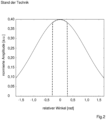
- the associated detection angle spectrum which can be detected by the optical imaging system 6 in this case, is in Fig.2 represented by the dot-dash line.
- the solid line represents the theoretically maximum possible angle spectrum, which depends solely on the aperture of the transmission system 3 and/or the optical imaging system 6.
- the normalized amplitude is represented in arbitrary units , and the relative angle in is on the x-axis Represented in radians in relation to the optical axis 7 of the optical imaging system 6 .
- the detection angle spectrum that can actually be detected is severely limited here compared to what is theoretically possible due to the requirement that it must be symmetrical to the optical axis 7 of the optical imaging system 6 .
- the device shown behaves in such a way that the object-side detection aperture cone 12 corresponds to the actually maximum possible aperture cone of the transmission system 3, the dimensions of which are specified solely by the corresponding data of an object-side lens of the transmission system 3.
- the detection aperture cone 13 can also be slightly smaller than the maximum possible aperture cone of the transmission system 3 .
- the object plane 1 in the example shown here encloses an angle with the optical axis of the transmission system 3, the amount of which is smaller than the opening angle of the object-side detection aperture cone 12 of the transmission system 3 and the object plane 1 - and thus also the plane of the light sheet 11 - At least partially within the object-side detection aperture cone 12 is located.
- the intermediate image plane 4 encloses an angle with the optical axis 5 of the transmission system 3, the amount of which is smaller than the opening angle of the intermediate image side detection aperture cone 13 of the transmission system 3, the intermediate image plane lies at least partially within the intermediate image side detection -Aperture cone 13. This is in Fig.1 clearly visible.
- the intermediate image plane 4 is therefore localized within the reflected detection aperture cone 13 .
- the optical imaging system 6 is aligned with its optical axis 7 perpendicular to the intermediate image plane 4 and collects fluorescent light at most in an image-side detection aperture cone 14, which is characterized here by the long dashed lines. Since fluorescent light or, in general, emission light, which propagates at an angle of greater than 90° relative to the optical axis 7 of the optical imaging system 6, cannot in principle be detected, the maximum theoretically possible sub-range of the detection angle spectrum in the xz plane, which is associated with the in Fig.1 shown structure can be grasped, marked by the triangle with the vertices A, B and C.
- this maximum theoretically possible partial area which is defined by the triangle ABC, is asymmetrical in relation to the optical axis 5 of the transmission system 3.
- the sub-area that can actually be captured by the optical imaging system 6 is sometimes even more restricted than the maximum theoretically possible sub-area. This depends on the aperture of the imaging optical system 6 .
- the detection angle range that can actually be detected by the optical imaging system 6 and identified by the triangle CDE covers a significantly larger angle range than the symmetrical, hatched cone according to the prior art, but is asymmetrically distributed around the optical axis 7 of the optical imaging system 6. This detection angle range, which is larger than in the prior art, results in a higher resolution of the device, even if the detection angle spectrum is distributed asymmetrically about the optical axis 7 of the optical imaging system 6 .
- the detection aperture cone 14 on the imaging side can be enlarged further if the numerical aperture of the optical imaging system 6 is also selected to be larger.
- the numerical aperture of the optical imaging system 6 is therefore preferably larger than the numerical aperture of the transmission system 3.
- a boundary surface is introduced in the intermediate image plane, which brings about a jump in the refractive index.
- a first optical medium is arranged between the optical transmission system 3 and the intermediate image plane 4 and a second optical medium is arranged between the intermediate image plane 4 and the optical imaging system 6 .
- the intermediate image plane 4 lies at the boundary between the first and second optical medium, ie in the interface.
- the second optical medium has a higher refractive index than the first optical medium.
- the optical media each cover the beam paths up to the transmission system 3 or optical imaging system 6, they can be immersion media, for example, or gel-like substances; glasses are also possible configurations.
- the sub-area that can actually be detected can be approximated as closely as possible to the theoretically possible one.
- an asymmetry remains which, in terms of imaging technology, results in an asymmetrical or non-point-symmetrical point spread function for the entire device.
- the evaluation unit 9 is preferably suitable for image processing, taking into account an asymmetrical point spread function based on the asymmetrical detection angle spectrum. In this way, the point spread function can be used for image evaluation and contribute to increasing sharpness as part of an unfolding.
- the evaluation unit is also suitable for taking into account or calculating a compressed point spread function, such as that which occurs on the described boundary surface in the intermediate image plane due to Snell's law of refraction.
- the detection angle spectra are shown for different configurations of the device.
- the images each show a section in the xz plane through the amplitude component of the light emitted by the sample, i.e. the detection angle spectrum with a solid line.
- the phase fraction is neglected in this case, which is adequate when considering fluorescence emission.
- the form of the detection angle spectrum is chosen arbitrarily and is only used for illustration.
- the abscissa represents the angle relative to the optical axis 7 of the optical imaging system 6.
- the numerical aperture of the optical transmission system 3 is 1.2 and is identical to the numerical aperture of the optical imaging system 6. Only one medium was used here, namely water with a refractive index of 1.33.
- the transmission system 3 is constructed symmetrically and the optical imaging system 6 is at an angle of 48° to the transmission system 3 in relation to the optical axes.
- the maximum theoretically possible detectable sub-range of the detection angle spectrum corresponding to triangle ABC in Fig.1 which can be detected behind the transmission system 3, is shown in dashed lines.
- this sub-range is clipped due to the aperture of the transmission system 3 and due to the fact that the intermediate image plane 4 lies within the detection aperture cone 13, to which the optical imaging system must detect perpendicularly.
- the section that can actually be detected corresponds to the triangle CDE in Fig.1 is in Figures 3-5 shown dotted.
- a further trimming results from the fact that the aperture of the optical imaging system 6 can again only cover a certain partial area, based on the optical axis 7 of the optical imaging system 6 the point spread function of the system is asymmetrical.
- the area that can actually be detected is increased by introducing a jump in the refractive index in the intermediate image plane 4 .
- Fig.5 shown here water with a refractive index of 1.33 is used as the first medium between the transmission system 3 and the intermediate image plane 4 and glass BK7 with a refractive index of 1.52 is used as the second medium between the intermediate image plane 4 and the optical imaging system.
- the numerical aperture of the optical imaging system 6 is then 1.329 and is within the realizable range due to the media selection.
- the theoretically possible spectrum is then fully recorded, it is indicated by the dotted line in Fig.5 shown.
- the resolution of the overall system can be increased if an asymmetrical, possibly compressed detection angle spectrum and, associated therewith, an asymmetrical and likewise possibly compressed point spread function are permitted during the detection.
Landscapes
- Physics & Mathematics (AREA)
- Chemical & Material Sciences (AREA)
- Analytical Chemistry (AREA)
- General Physics & Mathematics (AREA)
- Optics & Photonics (AREA)
- Engineering & Computer Science (AREA)
- Multimedia (AREA)
- Computer Vision & Pattern Recognition (AREA)
- Investigating Or Analysing Materials By Optical Means (AREA)
- Microscoopes, Condenser (AREA)
- Investigating, Analyzing Materials By Fluorescence Or Luminescence (AREA)
Description
Die Erfindung betrifft eine Vorrichtung zur Abbildung einer in einer Objektebene angeordneten Probe. Diese Vorrichtung umfasst ein optisches Übertragungssystem, welches einen Bereich der Probe von der Objektebene in eine Zwischenbildebene abbildet. Die Objektebene und die Zwischenbildebene schließen dabei mit einer optischen Achse des Übertragungssystems einen von 90° verschiedenen Winkel ein, das optische Übertragungssystem ist aus mehreren Linsen aufgebaut. Die Vorrichtung umfasst außerdem ein optisches Abbildungssystem mit einem Objektiv, dessen optische Achse senkrecht auf der Zwischenbildebene steht und welches auf die Zwischenbildebene fokussiert ist, so dass die Objektebene unverzerrt auf einen Detektor abbildbar ist. Schließlich umfasst die Vorrichtung auch eine Beleuchtungseinrichtung zur Beleuchtung der Probe mit einem Lichtblatt, wobei Beleuchtungslicht in der Zwischenbildebene oder in einer Pupillenebene in den Strahlengang des Übertragungssystems eingekoppelt und durch das Übertragungssystem auf die Probe gelenkt wird oder über einen separaten Beleuchtungsstrahlengang direkt in die Objektebene eingestrahlt wird. Dabei liegt das Lichtblatt im Wesentlichen in der Objektebene und legt die Richtung der Beleuchtung fest. Die Normale der Objektebene - die auch der Normalen des Lichtblattes entspricht - legt eine Detektionsrichtung fest.The invention relates to a device for imaging a sample arranged in an object plane. This device includes an optical transmission system which images a region of the sample from the object plane into an intermediate image plane. The object plane and the intermediate image plane enclose an angle different from 90° with an optical axis of the transmission system, the optical transmission system is made up of several lenses. The device also includes an optical imaging system with a lens whose optical axis is perpendicular to the intermediate image plane and which is focused on the intermediate image plane, so that the object plane can be imaged undistorted on a detector. Finally, the device also includes an illumination device for illuminating the sample with a light sheet, with illumination light being coupled into the beam path of the transmission system in the intermediate image plane or in a pupil plane and directed onto the sample by the transmission system, or being radiated directly into the object plane via a separate illumination beam path . The light sheet lies essentially in the object plane and determines the direction of the illumination. The normal of the object plane - which also corresponds to the normal of the light sheet - defines a detection direction.
Das optische Übertragungssystem besteht aus mehreren Linsen. Es kann symmetrisch aufgebaut sein, so dass die Abbildung durch das optische Übertragungssystem mit einem Maßstab von 1:1 erfolgt. Dies ist jedoch nicht zwingend notwendig, die Abbildung kann auch vergrößert oder verkleinert erfolgen.The optical transmission system consists of several lenses. It can be constructed symmetrically, so that the imaging through the optical transmission system takes place with a scale of 1:1. However, this is not absolutely necessary, the image can also be enlarged or reduced.
Eine solche Vorrichtung wird insbesondere bei der Untersuchung von biologischen Proben eingesetzt, bei der die Beleuchtung der Probe mit einem Lichtblatt, dessen Ebene die optische Achse der Detektion in einem von Null verschiedenen Winkel schneidet, erfolgt. Üblicherweise schließt dabei das Lichtblatt mit der Detektionsrichtung einen rechten Winkel ein. Mit dieser auch als SPIM (Selective Plane Illumination Microscopy) bezeichneten Technik lassen sich in relativ kurzer Zeit räumliche Aufnahmen auch dickerer Proben erstellen. Auf der Basis von optischen Schnitten kombiniert mit einer Relativbewegung in einer Richtung senkrecht zur Schnittebene ist eine bildliche, räumlich ausgedehnte Darstellung der Probe möglich.Such a device is used in particular when examining biological samples, in which the sample is illuminated with a light sheet whose plane intersects the optical axis of the detection at an angle other than zero. Usually, the light sheet encloses a right angle with the detection direction. With this technique, also known as SPIM ( Selective Plane Illumination Microscopy ), spatial recordings can also be made of thicker samples in a relatively short time. On the basis of optical sections combined with a relative movement in a direction perpendicular to the plane of the section, a pictorial, spatially extended representation of the sample is possible.
Die SPIM-Technik wird bevorzugt in der Fluoreszenzmikroskopie eingesetzt, wo sie dann auch als LSFM (Light Sheet Fluorescence Microscopy) bezeichnet wird. Gegenüber anderen etablierten Verfahren wie der konfokalen Laser-Scanning-Mikroskopie oder der Zwei-Photonen-Mikroskopie weist die LSFM-Technik mehrere Vorzüge auf: Da die Detektion im Weitfeld erfolgen kann, lassen sich größere Probenbereiche erfassen. Darüber hinaus ist die Lichtbelastung der Proben bei diesem Verfahren am geringsten, was unter anderem die Gefahr des Ausbleichens einer Probe reduziert, da die Probe nur durch ein dünnes Lichtblatt in einem von Null verschiedenen Winkel zur Detektionsrichtung beleuchtet wird. Anstelle eines rein statischen Lichtblattes kann auch ein quasistatisches Lichtblatt verwendet werden. Dieses wird erzeugt, indem die Probe mit einem Lichtstrahl schnell abgetastet wird. Die lichtblattartige Beleuchtung entsteht, wenn der Lichtstrahl einer sehr schnellen Relativbewegung zu der zu beobachtenden Probe unterworfen wird und dabei zeitlich aufeinanderfolgend mehrfach aneinandergereiht wird. Dabei wird die Integrationszeit der Kamera, auf deren Sensor die Probe abgebildet wird, sinnvollerweise so gewählt, dass die Abtastung innerhalb der Integrationszeit abgeschlossen wird.The SPIM technique is preferably used in fluorescence microscopy, where it is also referred to as LSFM ( Light Sheet Fluorescence Microscopy ). Compared to other established methods such as confocal laser scanning microscopy or two-photon microscopy, LSFM technology has several advantages: Since detection can take place in the wide field, larger sample areas can be recorded. In addition, the light exposure of the samples is the lowest with this method, which, among other things, reduces the risk of fading of a sample, since the sample is only illuminated by a thin sheet of light at a non-zero angle to the detection direction. Instead of a purely static light sheet, a quasi-static light sheet can also be used. This is generated by quickly scanning the sample with a light beam. The light sheet-like illumination occurs when the light beam is subjected to a very rapid relative movement to the sample to be observed and is lined up several times in succession. The integration time of the camera on whose sensor the sample is imaged is sensibly chosen so that the scanning is completed within the integration time.
Die SPIM-Technik ist in der Literatur inzwischen vielfach beschrieben, beispielsweise in der
Bei den üblichen SPIM-Anordnungen erfolgt die Beleuchtung über ein Linsensystem, welches in der Ebene der Probe liegt, die beleuchtet wird. Wird also beispielsweise von oben beobachtet, so muss die Beleuchtung von der Seite erfolgen. Übliche Präparationstechniken können daher nicht verwendet werden. Ein weiterer wesentlicher Nachteil liegt darin, dass sowohl das Beleuchtungsobjektiv als auch das Beobachtungsobjektiv räumlich nah beieinander angeordnet werden müssen, so dass für die Detektion eine Linse mit einer hohen numerischen Apertur genutzt werden kann, welche aus einem weiten Bereich Licht einfängt. Gleichzeitig muss jedoch auch ein Lichtblatt erzeugt werden. Diese mechanischen Beschränkungen können zu einer Einschränkung der numerischen Apertur und damit der Auflösung des abbildenden Systems führen.In the case of the usual SPIM arrangements, the illumination takes place via a lens system which lies in the plane of the sample which is illuminated. If, for example, observation is made from above, the lighting must come from the side. Conventional preparation techniques can therefore not be used. A further major disadvantage is that both the illumination lens and the observation lens have to be arranged spatially close to one another, so that a lens with a high numerical aperture can be used for detection, which lens captures light from a wide area. At the same time, however, a light sheet must also be generated. These mechanical limitations can limit the numerical aperture and thus the resolution of the imaging system.
Um diese Beschränkungen aufzuheben, wurden SPIM-Optiken entwickelt, bei denen dasselbe Objektiv für die Beleuchtung mit einem Lichtblatt und gleichzeitig für die Detektion von Fluoreszenz, welche von der Probe kommt, verwendet wird. Dabei erfolgt die Beleuchtung der Probe mit einem Lichtblatt über einen Teilbereich des Objektivs, welcher einen Randbereich dieses Objektivs einschließt, so dass die Beleuchtung also unter einem zur optischen Achse des Objektivs schrägen Winkel erfolgt. Für die Detektion wird dann ein gegenüberliegender Randbereich des Objektivs verwendet, so dass die Detektion im Mittel ebenfalls unter einem zur optischen Achse des Objektivs von Null verschiedenen Winkel erfolgt. Aufgrund der beschränkten numerischen Apertur des Objektivs beträgt dieser Winkel in der Regel weniger als die 90°, die sonst in der klassischen SPIM-Technik üblich ist.To overcome these limitations, SPIM optics were developed, using the same objective for illumination with a light sheet and simultaneous detection of fluorescence coming from the sample. In this case, the sample is illuminated with a light sheet over a partial area of the objective, which includes an edge area of this objective, so that the illumination therefore takes place at an angle that is oblique to the optical axis of the objective. An opposite edge area of the lens is then used for the detection, so that the detection also takes place on average at an angle that is different from zero to the optical axis of the lens. Due to the limited numerical aperture of the lens, this angle is usually less than the 90° that is otherwise used in classic SPIM technology is common.
Ein solcher Aufbau ist beispielsweise in der
Sofern keine Immersionsmedien verwendet werden, können die optischen Komponenten der beiden Teilsysteme identisch gewählt werden, sie sind jedoch spiegelverkehrt angeordnet, so dass die Abbildung im Maßstab 1:1 erfolgt.If no immersion media are used, the optical components of the two subsystems can be chosen to be identical, but they are arranged mirror-inverted so that the image is on a 1:1 scale.
Falls eines der beiden Teilsysteme als Immersionssystem ausgestaltet ist, sich das optische Element, welches der Probe am nächsten ist, also in einem Immersionsmedium befindet, so sollen gemäß der
Um nun eine vergrößerte Darstellung der Probe in der Objektebene zu erhalten, ist in der
Anstelle eines aus Linsen aufgebauten, transmissiven Übertragungssystems, wie es in der
Der
Eine ähnliche Anordnung wird in der
Aufgabe der Erfindung ist es, eine Vorrichtung der eingangs beschriebenen Art dahingehend zu verbessern, dass die bei der Detektion erzielbare Auflösung mit einfachen Mitteln verbessert wird.The object of the invention is to improve a device of the type described at the outset such that the resolution that can be achieved during detection is improved with simple means.
Diese Aufgabe wird durch die Merkmale der unabhängigen Ansprüche gelöst.This object is solved by the features of the independent claims.
Aufgrund des asymmetrischen Detektionswinkelspektrums, welches einen größeren Winkelbereich als im Stand der Technik einschließt, kann die Auflösung der mikroskopischen Vorrichtung erhöht werden. Die Halbwertsbreite der Punktspreizfunktion des Systems wird aufgrund des größeren Bereichs, der für die Detektion des Winkelspektrums zur Verfügung steht, reduziert, jedoch wird ihr aufgrund der Asymmetrie des Detektionswinkelspektrums gleichzeitig ebenfalls eine Asymmetrie aufgeprägt. Vorzugsweise umfasst die Vorrichtung daher auch einen Detektor und eine daran angeschlossene Auswerteeinheit zur Bildbearbeitung unter Berücksichtigung einer solchen asymmetrischen Punktspreizfunktion und/oder einer aufgrund der Grenzfläche gestauchten Punktspreizfunktion. Insbesondere indem das aufgenommene Bild mit der asymmetrischen Punktspreizfunktion entfaltet wird, lassen sich im Bild vorhandene Unschärfen besser korrigieren. Jedoch erhält man auch ohne eine Entfaltung mit der Punktspreizfunktion, die nur im Rahmen einer Bildbearbeitung erfolgen kann, ein besser aufgelöstes Bild als im Stand der Technik.Due to the asymmetric detection angle spectrum, which includes a larger angle range than in the prior art, the resolution of the microscopic device can be increased. The FWHM of the system's point spread function is reduced due to the larger range available for angular spectrum detection, however, due to the asymmetry of the detection angle spectrum, an asymmetry is also imposed on it at the same time. The device therefore preferably also includes a detector and an evaluation unit connected to it for image processing, taking into account such an asymmetrical point spread function and/or a point spread function that is compressed due to the interface. In particular, by unfolding the recorded image with the asymmetrical point spread function, the blurring that is present in the image can be better corrected. However, even without deconvolution using the point spread function, which can only take place as part of image processing, a better-resolution image is obtained than in the prior art.
Vorzugsweise schließen dabei die Objektebene und die Zwischenbildebene mit der optischen Achse des Übertragungssystems Winkel ein, deren Beträge kleiner als der Öffnungswinkel des objektseitigen bzw. des zwischenbildseitigen Detektions-Aperturkegels des Übertragungssystems sind. Die Objektebene und die Zwischenbildebene liegen außerdem mindestens teilweise im objektseitigen bzw. im zwischenbildseitigen Detektions-Aperturkegel.Preferably, the object plane and the intermediate image plane enclose angles with the optical axis of the transmission system, the amounts of which are smaller than the opening angle of the object-side or intermediate-image-side detection aperture cone of the transmission system. The object plane and the intermediate image plane also lie at least partially in the object-side or in the intermediate-image side detection aperture cone.
Das Zwischenbild bzw. die abgebildete Lichtblattebene zwischen Übertragungssystem und optischen Abbildungssystem liegt dann innerhalb des möglichen Detektionswinkelspektrums, welches von der Apertur des Übertragungssystems und seiner Brennweite abhängt und dem Detektions-Aperturkegel entspricht. Dies führt zu einer inhärenten Asymmetrie der detektierbaren Fluoreszenzwinkelverteilung in der durch die Ausbreitungsrichtung und die optische Achse des Übertragungssystems bzw. der optischen Achse des optischen Abbildungssystems aufgespannten Ebene, also senkrecht zur Lichtblattebene. Der maximal mögliche Teilbereich des erfassbaren Fluoreszenzwinkelspektrums in der genannten Ebene wird aufgrund der Lage der Zwischenbildebene im Detektions-Aperturkegel auf der Ausgangsseite des Übertragungssystems beschränkt und ist daher asymmetrisch bezogen auf die optische Achse des Übertragungssystems.The intermediate image or the imaged light sheet plane between the transmission system and the optical imaging system is then within the possible detection angle spectrum, which depends on the aperture of the transmission system and its focal length and corresponds to the detection aperture cone. This leads to an inherent asymmetry of the detectable fluorescence angle distribution in the plane spanned by the direction of propagation and the optical axis of the transmission system or the optical axis of the optical imaging system, ie perpendicular to the plane of the light sheet. The maximum possible partial range of the detectable fluorescence angle spectrum in said plane is limited due to the position of the intermediate image plane in the detection aperture cone on the output side of the transmission system and is therefore asymmetrical in relation to the optical axis of the transmission system.
Die beschriebene Vorrichtung zeichnet sich vorzugsweise dadurch aus, dass die Objektebene mindestens teilweise innerhalb des objektseitigen Detektions-Aperturkegels liegt und somit mit der optischen Achse des Übertragungssystems einen Winkel einschließt, dessen Betrag kleiner als der Öffnungswinkel des Detektions-Aperturkegels ist. Der objektseitige Detektions-Aperturkegel wird entsprechend durch das Übertragungssystem auf die Seite des Zwischenbildes übertragen und dort liegt entsprechend die Zwischenbildebene mindestens teilweise innerhalb des zwischenbildseitigen Detektions-Aperturkegels. Die optische Achse des Übertragungssystems schließt mit der Zwischenbildebene einen Winkel ein, dessen Betrag kleiner als der Öffnungswinkel des zwischenbildseitigen Detektions-Aperturkegels des Übertragungssystems ist. Somit dürfen in diesem Fall im Übertragungssystem keine störenden optischen Elemente angeordnet sein, die einen Teil des Detektionswinkelspektrums ausblenden könnten.The device described is preferably characterized in that the object plane lies at least partially within the object-side detection aperture cone and thus encloses an angle with the optical axis of the transmission system, the amount of which is smaller than the opening angle of the detection aperture cone. The object-side detection aperture cone is correspondingly transferred by the transmission system to the side of the intermediate image, and there the intermediate image plane lies at least partially within the intermediate-image-side detection aperture cone. The optical axis of the transmission system encloses an angle with the intermediate image plane, the amount of which is smaller than the opening angle of the intermediate image-side detection aperture cone of the transmission system. In this case, no interfering optical elements that could hide part of the detection angle spectrum may be arranged in the transmission system.
Für die Detektion beispielsweise von emittiertem Fluoreszenzlicht steht dann der gesamte Bereich der objektseitigen Apertur des Übertragungssystems zur Verfügung, so dass der Detektions-Aperturkegel des Übertragungssystems nur durch die numerische Apertur des Übertragungssystems auf der Objektseite beschränkt wird. Im Stand der Technik wird meist ein Teil des objektseitigen Objektivs des Übertragungssystems für die Einkopplung von Anregungslicht genutzt, dieser Teil des Objektivs steht für die Detektion dann nicht mehr zur Verfügung, weil beispielsweise das Beleuchtungslicht über einen Spiegel, welcher sich im Strahlengang des Übertragungssystems befindet, eingekoppelt wird. Entsprechend kann in diesem Fall der maximal mögliche, theoretisch zur Verfügung stehende Detektions-Aperturkegel, der die gesamte Apertur des objektseitigen Objektivs des Übertragungssystems ausnutzt, nicht erreicht werden. Als Konsequenz befindet sich die Objektebene und damit auch die Lichtblattebene nicht im tatsächlich möglichen Detektions-Aperturkegel, gleiche Verhältnisse herrschen auf der Zwischenbildseite, auch hier liegt dann die Zwischenbildebene außerhalb des zwischenbildseitigen Aperturkegels des Übertragungssystems. Als Konsequenz ist im Stand der Technik das Winkelspektrum symmetrisch zur optischen Achse des optischen Abbildungssystems ausgebildet, welches zudem durch die Apertur des optischen Abbildungssystems, welcher das Zwischenbild in eine Bildebene abbildet, eingeschränkt wird.The entire area of the object-side aperture of the transmission system is then available for the detection of emitted fluorescent light, for example, so that the detection aperture cone of the transmission system is limited only by the numerical aperture of the transmission system on the object side. In the prior art, a part of the objective lens of the transmission system on the object side is usually used for coupling in excitation light, this part of the objective lens is then no longer available for detection because, for example, the illuminating light is reflected via a mirror located in the beam path of the transmission system. is coupled. Accordingly, in this case the maximum possible, theoretically available detection aperture cone, which utilizes the entire aperture of the object-side lens of the transmission system, cannot be achieved. As a consequence, the object plane and thus also the light sheet plane are not in the actually possible detection aperture cone, the same conditions prevail on the intermediate image side, here too the intermediate image plane is then outside the intermediate image side aperture cone of the transmission system. As a consequence, in the prior art, the angle spectrum is designed symmetrically to the optical axis of the optical imaging system, which is also restricted by the aperture of the optical imaging system, which images the intermediate image in an image plane.
Die Zwischenbildebene ist also teilweise innerhalb des vom Übertragungssystem übertragenen - bei einer Übertragung im Maßstab 1:1 gespiegelten - Detektions-Aperturkegels lokalisiert. Das optische Abbildungssystem ist dem Übertragungssystem nachgeschaltet und in seiner optischen Achse senkrecht zu dieser Zwischenbildebene ausgerichtet. Es sammelt Fluoreszenzlicht bzw. zu detektierendes Licht innerhalb eines weiteren Detektions-Aperturkegels, nämlich des optischen Abbildungssystems ein. Da die Zwischenbildebene innerhalb des übertragenen Detektions-Aperturkegels liegt, kann das optische Abbildungssystem einen größeren Detektionswinkelbereich erfassen, als dies im Stand der Technik möglich ist, dies führt hier zwangsläufig zu einer asymmetrischen Verteilung des Detektionswinkelbereichs. Da der erfassbare Detektionswinkelbereich - wenn auch asymmetrisch - vergrößert wird, kann auf diese Weise die Auflösung insgesamt erhöht werden.The intermediate image plane is thus partially localized within the detection aperture cone transmitted by the transmission system—mirrored in the case of transmission on a scale of 1:1. The optical imaging system is connected downstream of the transmission system and its optical axis is aligned perpendicularly to this intermediate image plane. It collects fluorescent light or light to be detected within a further detection aperture cone, namely the optical imaging system. Since the intermediate image plane lies within the transmitted detection aperture cone, the optical imaging system can cover a larger detection angle range than is possible in the prior art, which here inevitably leads to an asymmetrical distribution of the detection angle range. Since the detection angle range that can be detected is increased—albeit asymmetrically—the overall resolution can be increased in this way.
Dabei ist es vorteilhaft, einen möglichst große numerische Apertur des optischen Abbildungssystems zu wählen, insbesondere diese größer als die numerische Apertur des Übertragungssystems zu wählen, um einen möglichst großen Detektionswinkelbereich zu erfassen um die Auflösung zu maximieren.In this case, it is advantageous to select the largest possible numerical aperture of the optical imaging system, in particular to select this larger than the numerical aperture of the transmission system, in order to cover the largest possible detection angle range in order to maximize the resolution.
Erfindungsgemäß ist die Vorrichtung so ausgestaltet, dass zwischen dem optischen Übertragungssystem und dem optischen Abbildungssystem ein erstes und ein zweites optisches Medium angeordnet sind. Dabei ist das erste optische Medium zwischen dem optischen Übertragungssystem und der Zwischenbildebene angeordnet und das zweite optische Medium zwischen der Zwischenbildebene und dem optischen Abbildungssystem. Die Zwischenbildebene liegt dann in der Grenzfläche zwischen erstem und zweitem optischen Medium, das zweite optische Medium hat einen höheren Brechungsindex als das erste optische Medium. Die Medien können als Flüssigkeiten, beispielsweise als Immersionsmedien ausgestaltet sein, oder auch als gelartige oder glasartige Medien, die ebenfalls die Funktion eines Immersionsmediums übernehmen können, wenn sie direkt an das optische Übertragungssystem bzw. das optische Abbildungssystem anschließen. Die Grenzfläche kann auch optisch mikrostrukturiert sein um effektiv einen größeren Sprung im Brechungsindex zu erreichen, als er für einfache Grenzflächen möglich wäre. Bei einer entsprechend hohen numerischen Apertur des optischen Abbildungssystems, bevorzugt einer größeren Apertur als die des optischen Übertragungssystems, und bei einem Brechungsindexsprung mit der Zwischenbildebene als Grenzfläche kann - aufgrund des Snelliusschen Brechungsgesetzes - der tatsächlich erfassbare Winkelbereich dem theoretisch möglichen Winkelbereich sehr stark angenähert werden, jedoch ist stets eine Asymmetrie vorhanden.According to the invention, the device is designed in such a way that a first and a second optical medium are arranged between the optical transmission system and the optical imaging system. In this case, the first optical medium is arranged between the optical transmission system and the intermediate image plane and the second optical medium is arranged between the intermediate image plane and the optical imaging system. The intermediate image plane then lies in the interface between the first and second optical medium, the second optical medium has a higher refractive index than the first optical medium. The media can be designed as liquids, for example as immersion media, or also as gel-like or glass-like media, which can also assume the function of an immersion medium if they are connected directly to the optical transmission system or the optical imaging system. The interface can also be optically microstructured to effectively achieve a larger jump in refractive index than would be possible with simple interfaces. With a correspondingly high numerical aperture of the optical imaging system, preferably a larger aperture than that of the optical transmission system, and with a jump in the refractive index with the intermediate image plane as the boundary surface, the actually detectable angular range can be very closely approximated to the theoretically possible angular range - due to Snell's law of refraction, however there is always an asymmetry.
Die Einführung einer Grenzfläche geht einher mit einer Stauchung des Winkelspektrums eines Punktstrahlers, d.h. der Punktspreizfunktion, welche hier nicht als Verzerrung angesehen wird, jedoch bei einer späteren Auswertung entsprechend berücksichtigt werden muss.The introduction of an interface goes hand in hand with a compression of the angular spectrum of a point radiator, i.e. the point spread function, which is not regarded as distortion here, but must be taken into account accordingly in a later evaluation.
Die vorangehend beschriebene Vorrichtung wird dazu verwendet, eine in einer Objektebene angeordnete Probe mit einem Lichtblatt zu beleuchten, wobei das Lichtblatt im Wesentlichen in der Objektebene liegt und eine Beleuchtungsrichtung festlegt, und die Normale der Objektebene eine Detektionsrichtung festlegt. Mit einem optischen Übertragungssystem wird ein Bereich der Probe von der Objektebene in eine Zwischenbildebene abgebildet, wobei die Objektebene und die Zwischenbildebene mit einer optischen Achse des Übertragungssystems einen von 90° verschiedenen Winkel einschließen. Die Zwischenbildebene wird mit einem optischen Abbildungssystem mit einem Objektiv, dessen optische Achse senkrecht auf der Zwischenbildebene steht und das auf die Zwischenbildebene fokussiert ist, unverzerrt auf einen Detektor abgebildet. Dort wird es als Bild registriert, wobei das optische Abbildungssystem (6) einen um die optische Achse (7) asymmetrisch verteilten Detektionswinkelbereich erfasst. Das registrierte Bild wird anschließend in einer mit dem Detektor (8) verbundenen Auswerteeinheit unter Berücksichtigung einer asymmetrischen Punktspreizfunktion auf Basis des asymmetrischen Detektionswinkelspektrums und/oder einer gestauchten Punktspreizfunktion bearbeitet. Zwischen dem optischen Übertragungssystem und der Zwischenbildebene ist ein erstes optisches Medium und zwischen der Zwischenbildebene und dem optischen Abbildungssystem ist ein zweites optisches Medium angeordnet. Die Zwischenbildebene liegt in der Grenzfläche zwischen erstem und zweitem optischen Medium, das zweite optische Medium hat einen höheren Brechungsindex als das erste optische Medium.The device described above is used to illuminate a sample arranged in an object plane with a light sheet, the light sheet lying essentially in the object plane and defining an illumination direction, and the normal of the object plane defining a detection direction. An area of the sample is imaged from the object plane into an intermediate image plane using an optical transmission system, with the object plane and the intermediate image plane forming an angle that differs from 90° with an optical axis of the transmission system. The intermediate image plane is imaged undistorted onto a detector using an optical imaging system with a lens whose optical axis is perpendicular to the intermediate image plane and which is focused on the intermediate image plane. There it is registered as an image, with the optical imaging system (6) capturing a detection angle range distributed asymmetrically around the optical axis (7). The registered image is then processed in an evaluation unit connected to the detector (8), taking into account an asymmetric point spread function based on the asymmetric detection angle spectrum and/or a compressed point spread function. A first optical medium is arranged between the optical transmission system and the intermediate image plane and a second optical medium is arranged between the intermediate image plane and the optical imaging system. The intermediate image plane lies in the interface between the first and second optical medium, the second optical medium has a higher refractive index than the first optical medium.
Nachfolgend wird die Erfindung beispielsweise anhand der beigefügten Zeichnungen, die auch erfindungswesentliche Merkmale offenbaren, noch näher erläutert. Es zeigen:
- Fig.1
- den Aufbau einer Vorrichtung zur Abbildung einer Probe,
- Fig.2
- die detektierbare Winkelverteilung vom Detektionslicht nach dem Stand der Technik,
- Fig.3
- Detektionswinkelspektren für eine erste Ausgestaltung einer nicht erfindungsgemäßen Vorrichtung gemäß
Fig.1 , - Fig.4
- Detektionswinkelspektren für eine zweite nicht erfindungsgemäße Ausgestaltung einer solchen Vorrichtung,
- Fig.5
- Detektionswinkelspektren für eine dritte Ausgestaltung einer solchen Vorrichtung.
- Fig.1
- the construction of a device for imaging a sample,
- Fig.2
- the detectable angular distribution of the detection light according to the prior art,
- Fig.3
- Detection angle spectra according to a first embodiment of a device not according to the invention
Fig.1 , - Fig.4
- Detection angle spectra for a second embodiment of such a device not according to the invention,
- Fig.5
- Detection angle spectra for a third embodiment of such a device.
Anhand von
Die Vorrichtung umfasst außerdem ein optisches Abbildungssystem 6 mit einem Objektiv, dessen optische Achse 7 senkrecht auf der Zwischenbildebene 4 steht und welches auf die Zwischenbildebene 4 fokussiert ist, so dass insgesamt die Objektebene 1 unverzerrt auf einen Detektor 8 abbildbar ist. An den Detektor 8 ist eine Auswerteeinheit 9 zur Bildbearbeitung angeschlossen.The device also includes an
Schließlich umfasst die Vorrichtung zur Abbildung der Probe 2 auch eine Beleuchtungseinrichtung 10 zur Beleuchtung der Probe 2 mit einem Lichtblatt 11. Bei der in
Die Detektionsrichtung steht hier senkrecht auf der Objektebene 1 bzw. der Zwischenbildebene 4. Die Apertur des probenseitigen Objektivs des optischen Übertragungssystems 3 beschränkt in Zusammenwirkung mit dem Fokus den maximal möglichen Winkelbereich, in dem Emissionslicht - beispielsweise Fluoreszenzlicht, was durch das Lichtblatt angeregt wurde - detektiert werden kann. Dieser maximal mögliche Winkelbereich ist für die xz-Ebene objektseitig und zwischenbildseitig durch die kurzgestrichelten Linien gekennzeichnet, räumlich betrachtet wird durch die Apertur ein objektseitiger Detektions-Aperturkegel 12 und ein zwischenbildseitiger Detektions-Aperturkegel 13 festgelegt, dessen Schnitt in der xz-Ebene hier dargestellt ist. Das Übertragungssystem 3 ist hier symmetrisch aufgebaut, so dass der zwischenbildseitige Detektions-Aperturkegel 13 einem gespiegelten objektseitigen Detektions-Aperturkegel 12 entspricht.The detection direction is perpendicular to the
Im Stand der Technik ist der Detektionswinkelbereich auf einen symmetrisch um die Detektionsachse liegenden Ausschnitt des objektseitigen Aperturkegels 12 beschränkt, welcher hier durch den schraffierten Bereich innerhalb des objektseitigen Detektions-Aperturkegels 12 und entsprechend durch einen schraffierten Bereich auf der Zwischenbildseite dargestellt ist. Im Stand der Technik hat dies seine Begründung darin, dass ein Teil des Strahlengangs für die Beleuchtung freigehalten wird und / oder dass der Detektionsstrahlengang im optischen Abbildungssystem beschränkt wird und / oder dass bei der Bildauswertung keine zusätzlichen Maßnahmen aufgrund eines asymmetrischen Detektionswinkelspektrums vorgenommen werden müssen, die Auswertung also wesentlich einfacher ist.In the prior art, the detection angle range is limited to a section of the object-
Das zugehörige Detektionswinkelspektrum, was vom optischen Abbildungssystem 6 in diesem Fall detektiert werden kann, ist in
Bei der in
Die Zwischenbildebene 4 ist also innerhalb des gespiegelten Detektions-Aperturkegels 13 lokalisiert. Das optische Abbildungssystem 6 ist mit seiner optischen Achse 7 senkrecht zur Zwischenbildebene 4 ausgerichtet und sammelt Fluoreszenzlicht maximal in einem abbildungsseitigen Detektions-Aperturkegel 14 ein, welcher hier durch die lang gestrichelten Linien gekennzeichnet wird. Da Fluoreszenzlicht bzw. allgemein Emmissionslicht, welches in einem Winkel von größer als 90° relativ zur optischen Achse 7 des optischen Abbildungssystems 6 propagiert, prinzipiell nicht erfasst werden kann, wird der maximal theoretisch mögliche Teilbereich des Detektionswinkelspektrums in der xz-Ebene, der mit dem in
Der vom optischen Abbildungssystem 6 tatsächlich erfassbare Teilbereich ist mitunter noch stärker eingeschränkt als der maximal theoretisch mögliche Teilbereich. Dies hängt von der Apertur des optischen Abbildungssystems 6 ab. In jedem Fall umfasst der durch das optische Abbildungssystem 6 tatsächlich erfassbare, durch das Dreieck CDE gekennzeichnete Detektionswinkelbereich einen wesentlich größeren Winkelbereich als der symmetrische, schraffierte Kegel entsprechend dem Stand der Technik, ist jedoch asymmetrisch um die optische Achse 7 des optischen Abbildungssystems 6 verteilt. Dieser gegenüber dem Stand der Technik größere Detektionswinkelbereich resultiert in einer höheren Auflösung der Vorrichtung, auch wenn das Detektionswinkelspektrum asymmetrisch um die optische Achse 7 des optischen Abbildungssystems 6 verteilt ist.The sub-area that can actually be captured by the
Dabei kann der abbildungsseitige Detektions-Aperturkegel 14 weiter vergrößert werden, wenn auch die numerische Apertur des optischen Abbildungssystems 6 größer gewählt wird. Vorzugsweise ist daher die numerische Apertur des optischen Abbildungssystems 6 größer als die numerische Apertur des Übertragungssystems 3. In der Zwischenbildebene wird eine Grenzfläche eingeführt, die einen Brechungsindexsprung bewirkt. Dazu wird zwischen dem optischen Übertragungssystem 3 und der Zwischenbildebene 4 ein erstes optisches Medium angeordnet und zwischen der Zwischenbildebene 4 und dem optischen Abbildungssystem 6 ein zweites optisches Medium. Die Zwischenbildebene 4 liegt an der Grenze zwischen erstem und zweiten optischen Medium, also in der Grenzfläche. Das zweite optische Medium hat einen höheren Brechungsindex als das erste optische Medium. Die optischen Medien decken jeweils die Strahlengänge bis zum Übertragungssystem 3 bzw. optischen Abbildungssystem 6 ab, es kann sich beispielsweise um Immersionsmedien handeln, oder um gelartige Substanzen, auch Gläser sind mögliche Ausgestaltungen. Auf diese Weise kann der tatsächlich erfassbare Teilbereich dem theoretisch möglichen weitest möglich angenähert werden. In jedem Falle bleibt eine Asymmetrie, die abbildungstechnisch eine asymmetrische bzw. nicht punktsymmetrische Punktspreizfunktion für die gesamte Vorrichtung ergibt. Vorzugsweise ist die Auswerteeinheit 9 zur Bildbearbeitung geeignet unter Berücksichtigung einer asymmetrischen Punktspreizfunktion auf Basis des asymmetrischen Detektionswinkelspektrums, auf diese Weise kann die Punktspreizfunktion für die Bildauswertung herangezogen werden und im Rahmen einer Entfaltung zur Erhöhung der Schärfe beitragen. Alternativ oder ergänzend ist die Auswerteeinheit auch zur Berücksichtigung bzw. Verrechnung einer gestauchten Punktspreizfunktion geeignet, wie sie aufgrund des Snelliusschen Brechungsgesetzes an der beschriebenen Grenzfläche in der Zwischenbildebene auftritt, geeignet.In this case, the
In den
Bei dem in
Während also der tatsächlich erfassbare Bereich gegenüber dem Stand der Technik schon vergrößert ist, kann zur Erhöhung der Auflösung versucht werden, einen noch größeren Teil des gestrichelt dargestellten, theoretisch möglichen Spektrums zu erfassen. Dieser - nicht von der Erfindung umfasste - Fall ist in
Während der Erhöhung der numerischen Apertur des optischen Abbildungssystems 6 daher Grenzen gesetzt sind, erfolgt eine Vergrößerung des tatsächlich detektierbaren Bereichs, indem in der Zwischenbildebene 4 ein Brechungsindexsprung eingeführt wird. Dies ist in
Wenn ein asymmetrisches, ggf. gestauchtes Detektionswinkelspektrum und damit einhergehend eine asymmetrisch und ebenfalls ggf. gestauchte Punktspreizfunktion bei der Detektion zugelassen werden, lässt sich die Auflösung des Gesamtsystems erhöhen.The resolution of the overall system can be increased if an asymmetrical, possibly compressed detection angle spectrum and, associated therewith, an asymmetrical and likewise possibly compressed point spread function are permitted during the detection.
- 11
- Objektebeneobject level
- 22
- Probesample
- 33
- optisches Übertragungssystemoptical transmission system
- 44
- Zwischenbildebeneintermediate image level
- 55
- optische Achseoptical axis
- 66
- optisches Abbildungssystemoptical imaging system
- 77
- optische Achseoptical axis
- 88th
- Detektordetector
- 99
- Auswerteeinheitevaluation unit
- 1010
- Beleuchtungseinrichtunglighting device
- 1111
- Lichtblattlight sheet
- 1212
- objektseitiger Detektions-Aperturkegelobject-side detection aperture cone
- 1313
- zwischenbildseitiger Detektions-Aperturkegelinterimage-side detection aperture cone
- 1414
- abbildungsseitiger Detektions-Aperturkegelimage-side detection aperture cone
- A, B, C, D, E, FA, B, C, D, E, F
- Eckpunkte von Dreieckenvertices of triangles
Claims (7)
- Apparatus for imaging a sample (2) arranged in an object plane (1), comprising- an optical transfer system (3), which images a region of the sample (2) from the object plane (1) into an intermediate image plane (4),- wherein the object plane (1) and the intermediate image plane (4) enclose with an optical axis (5) of the transfer system (3) an angle that differs from 90° and the optical transfer system (3) is made up of a plurality of lenses,- an optical imaging system (6) having an objective, the optical axis (7) of which is perpendicular to the intermediate image plane (4) and which is focused at the intermediate image plane (4) such that the object plane (1) is able to be imaged onto a detector (8) without distortion,- an illumination device (10) for illuminating the sample (2) with a light sheet (11), wherein the light sheet (11) is located substantially in the object plane (1) and defines an illumination direction, and the normal of the object plane (1) defines a detection direction,- characterized in that- the optical imaging system (6) has an aperture with which a detection angle region which is asymmetrically distributed about the optical axis (7) of the objective is captured and imaged onto a detector (8) and- a first optical medium is arranged between the optical transfer system (3) and the intermediate image plane (4) and a second optical medium is arranged between the intermediate image plane (4) and the optical imaging system, wherein the intermediate image plane (4) is located in the interface between the first and the second optical medium and the second optical medium has a greater refractive index than the first optical medium.
- Apparatus according to Claim 1, characterized in that the object plane (1) and the intermediate image plane (4) enclose with the optical axis (5) of the transfer system (3) in each case an angle having an absolute value that is less than the opening angle of an object-side detection aperture cone (12) or of an intermediate-image-side detection aperture cone (13) of the transfer system (3), and the object plane (1) and the intermediate image plane (4) are located partially within the object-side detection aperture cone (12) or the intermediate-image-side detection aperture cone (13).
- Apparatus according to Claim 1 or 2, comprising an evaluation unit (9) connected to the detector (8) for image processing while taking into account an asymmetric point spread function based on the asymmetric detection angle spectrum and/or a compressed point spread function.
- Apparatus according to one of Claims 1 to 3, characterized in that the numerical aperture of the optical imaging system (6) is greater than the numerical aperture of the transfer system (3).
- Apparatus according to one of Claims 1 to 4, characterized in that the transfer system (3) is set up symmetrically with respect to a plane of symmetry between the subsystems perpendicular to the optical axis (5) of the transfer system (3), with the result that the imaging through the transfer system (3) is effected at an imaging scale of 1:1, and/or that the transfer system (3) has a catadioptric design.
- Method for imaging a sample (2) arranged in an object plane (1), wherein- the sample is illuminated with a light sheet (11), wherein the light sheet (11) is located substantially in the object plane (1) and defines an illumination direction, and the normal of the object plane (1) defines a detection direction,- a region of the sample (2) is imaged from the object plane (1) into an intermediate image plane (4) using an optical transfer system (3), wherein the object plane (1) and the intermediate image plane (4) enclose with an optical axis (5) of the transfer system (3) an angle that differs from 90°,- using an optical imaging system (6) having an objective, the optical axis (7) of which is perpendicular to the intermediate image plane (4) and which is focused at the intermediate image plane (4), the intermediate image plane (4) is imaged onto a detector (8) without distortion and is registered there as an image, wherein the optical imaging system (6) has an aperture that captures a detection angle region that is asymmetrically distributed about the optical axis (7), wherein a first optical medium is arranged between the optical transfer system (3) and the intermediate image plane (4) and a second optical medium is arranged between the intermediate image plane (4) and the optical imaging system, wherein the intermediate image plane (4) is located in the interface between the first and the second optical medium and the second optical medium has a greater refractive index than the first optical medium,- the registered image is processed in an evaluation unit connected to the detector (8) while taking into account an asymmetric point spread function based on the asymmetric detection angle spectrum and/or a compressed point spread function.
- Method according to Claim 6, characterized in that the object plane (1) and the intermediate image plane (4) are located partially within the object-side detection aperture cone (12) or the intermediate-image-side detection aperture cone (13).
Applications Claiming Priority (2)
| Application Number | Priority Date | Filing Date | Title |
|---|---|---|---|
| DE102014113827.9A DE102014113827A1 (en) | 2014-09-24 | 2014-09-24 | Device for imaging a sample |
| PCT/EP2015/069869 WO2016045913A1 (en) | 2014-09-24 | 2015-08-31 | Device for imaging a sample |
Publications (3)
| Publication Number | Publication Date |
|---|---|
| EP3198323A1 EP3198323A1 (en) | 2017-08-02 |
| EP3198323B1 EP3198323B1 (en) | 2020-01-29 |
| EP3198323B2 true EP3198323B2 (en) | 2023-03-08 |
Family
ID=54014824
Family Applications (1)
| Application Number | Title | Priority Date | Filing Date |
|---|---|---|---|
| EP15756911.2A Active EP3198323B2 (en) | 2014-09-24 | 2015-08-31 | Device for imaging a sample |
Country Status (6)
| Country | Link |
|---|---|
| US (1) | US10477124B2 (en) |
| EP (1) | EP3198323B2 (en) |
| JP (1) | JP6829527B2 (en) |
| CN (1) | CN106716217B (en) |
| DE (1) | DE102014113827A1 (en) |
| WO (1) | WO2016045913A1 (en) |
Families Citing this family (3)
| Publication number | Priority date | Publication date | Assignee | Title |
|---|---|---|---|---|
| DE102016011227C5 (en) * | 2016-09-19 | 2020-04-09 | Leica Microsystems Cms Gmbh | Microscope system and method for imaging a sample using a microscope system |
| DE102020204066A1 (en) | 2020-03-30 | 2021-09-30 | Leica Microsystems Cms Gmbh | Optical arrangement for an inclined plane microscope to improve the resolution |
| DE102020209889A1 (en) * | 2020-08-05 | 2022-02-10 | Carl Zeiss Microscopy Gmbh | Microscope and method for microscopic imaging with variable illumination |
Citations (4)
| Publication number | Priority date | Publication date | Assignee | Title |
|---|---|---|---|---|
| US5004307A (en) † | 1990-04-12 | 1991-04-02 | The Board Of Trustees Of The Leland Stanford Junior University | Near field and solid immersion optical microscope |
| US20040240047A1 (en) † | 2003-02-21 | 2004-12-02 | Shafer David R. | Catadioptric imaging system for broad band microscopy |
| WO2008078083A1 (en) † | 2006-12-22 | 2008-07-03 | Isis Innovation Limited | Focusing apparatus and method |
| WO2010012980A1 (en) † | 2008-07-31 | 2010-02-04 | Imperial Innovations Limited | Optical arrangement for oblique plane microscopy |
Family Cites Families (11)
| Publication number | Priority date | Publication date | Assignee | Title |
|---|---|---|---|---|
| US498048A (en) | 1893-05-23 | Pipe-wrench | ||
| JPH0519172A (en) * | 1991-07-09 | 1993-01-29 | Nikon Corp | Laser scanning microscope |
| JP2002054909A (en) * | 2000-08-11 | 2002-02-20 | Dainippon Screen Mfg Co Ltd | Image acquisition device |
| US20060291048A1 (en) * | 2001-03-19 | 2006-12-28 | Dmetrix, Inc. | Multi-axis imaging system with single-axis relay |
| DE10257423A1 (en) | 2002-12-09 | 2004-06-24 | Europäisches Laboratorium für Molekularbiologie (EMBL) | Microscope used in molecular biology comprises a focussing arrangement producing an extended planar object illumination region, a detection device, and a movement arrangement |
| CN1837890A (en) * | 2006-03-29 | 2006-09-27 | 哈尔滨工业大学 | Image recovery and pupil filtering type transverse super-resolution confocal microscopic imaging method and apparatus |
| DE102011000835C5 (en) | 2011-02-21 | 2019-08-22 | Leica Microsystems Cms Gmbh | Scanning microscope and method for light microscopic imaging of an object |
| ES2898616T3 (en) * | 2012-04-03 | 2022-03-08 | Univ Court Univ St Andrews | High resolution images of extended volumes |
| JP6051605B2 (en) | 2012-06-13 | 2016-12-27 | ソニー株式会社 | Display device, display control method, and program |
| DE102012013163B4 (en) | 2012-07-02 | 2022-08-25 | Carl Zeiss Microscopy Gmbh | Microscope and method of light sheet microscopy |
| DE102013105586B4 (en) | 2013-05-30 | 2023-10-12 | Carl Zeiss Ag | Device for imaging a sample |
-
2014
- 2014-09-24 DE DE102014113827.9A patent/DE102014113827A1/en active Pending
-
2015
- 2015-08-31 CN CN201580051470.3A patent/CN106716217B/en active Active
- 2015-08-31 WO PCT/EP2015/069869 patent/WO2016045913A1/en not_active Ceased
- 2015-08-31 EP EP15756911.2A patent/EP3198323B2/en active Active
- 2015-08-31 US US15/514,453 patent/US10477124B2/en active Active
- 2015-08-31 JP JP2017515697A patent/JP6829527B2/en active Active
Patent Citations (4)
| Publication number | Priority date | Publication date | Assignee | Title |
|---|---|---|---|---|
| US5004307A (en) † | 1990-04-12 | 1991-04-02 | The Board Of Trustees Of The Leland Stanford Junior University | Near field and solid immersion optical microscope |
| US20040240047A1 (en) † | 2003-02-21 | 2004-12-02 | Shafer David R. | Catadioptric imaging system for broad band microscopy |
| WO2008078083A1 (en) † | 2006-12-22 | 2008-07-03 | Isis Innovation Limited | Focusing apparatus and method |
| WO2010012980A1 (en) † | 2008-07-31 | 2010-02-04 | Imperial Innovations Limited | Optical arrangement for oblique plane microscopy |
Non-Patent Citations (11)
| Title |
|---|
| ANSELMI ET AL.: "Three-dimensional imaging and photostimulation by remote- focusing and holographic light patterning", PNAS, vol. 108, no. 49, 6 December 2011 (2011-12-06), pages 19504 - 19509, DOI: 10.1073/pnas.1109111108 † |
| BOTCHERBY ET AL.: "An optical technique for remote focusing in microscopy", OPTICS COMMUNICATIONS, vol. 281, 2008, pages 880 - 887, DOI: 10.1016/j.optcom.2007.10.007 † |
| Broschure der Patentinhaberin aus dem Jahr 2007 † |
| C. Dunsby, "Optically sectioned imaging by oblique plane microscopy", Proc. SPIE 7367, Advanced Microscopy Techniques, 73670H, 1. Juli 2009; doi:10.1117/12.835143 † |
| DUNSBY: "Optically sectioned imaging by oblique plane microscopy", OPTICS EXPRESS, vol. 16, no. 25, 8 December 2008 (2008-12-08), pages 20306 - 20316 † |
| Internet Leica Microsystems, "Echtzeit-3D-Bildgebung lebender Organismen bei sub-zellulärer Auflösung" 08.11.2016, (gefunden 03.02.2022) † |
| KIM ET AL.: "Vectorial point spread function and optical transfer function in oblique plane imaging", OPTICS EXPRESS, vol. 22, no. 9, 1 May 2014 (2014-05-01), pages 11140 - 11151 † |
| Rechnung der Einsprechenden aus dem Jahr 2010 † |
| S. Kumar et al., "High-speed 2D and 3D fluorescence microscopy of cardiac myocytes", Optics Express, Val. 19. Seiten 13839 - 13847, 18. Juli 2011 † |
| SIBARITA: "Deconvolution Microscopy", ADVANCES IN BIOCHEMICAL ENGINEERING, vol. 95, 2005, Berlin , Heidelberg, pages 201 - 243 † |
| Stellungnahme von Prof. Dr. Dunsby † |
Also Published As
| Publication number | Publication date |
|---|---|
| JP6829527B2 (en) | 2021-02-10 |
| US20170280076A1 (en) | 2017-09-28 |
| DE102014113827A1 (en) | 2016-03-24 |
| EP3198323B1 (en) | 2020-01-29 |
| US10477124B2 (en) | 2019-11-12 |
| JP2017530404A (en) | 2017-10-12 |
| EP3198323A1 (en) | 2017-08-02 |
| CN106716217B (en) | 2020-03-03 |
| CN106716217A (en) | 2017-05-24 |
| WO2016045913A1 (en) | 2016-03-31 |
Similar Documents
| Publication | Publication Date | Title |
|---|---|---|
| EP3489735B1 (en) | Method and arrangement for light sheet microscopy | |
| EP2535754B1 (en) | Sampling microscope and method for imaging an object using a light microscope | |
| DE202014011312U1 (en) | Microscope, focusing unit, liquid holding unit and optical unit | |
| EP3440491B1 (en) | Microscope and method for imaging a sample | |
| WO2014191381A1 (en) | Device for imaging a sample | |
| LU92925B1 (en) | Method for examining a sample by means of light-sheet microscopy and light-sheet microscope | |
| EP1882970A1 (en) | Laser scanning microscope for fluorescence analysis | |
| EP3447559A1 (en) | High resolution 2d microscopy with improved cut thickness | |
| WO2011018181A1 (en) | Microscope for measuring total reflection fluorescence | |
| EP3198323B2 (en) | Device for imaging a sample | |
| EP2290423B1 (en) | Scanning-microscope for optical scanning of samples with a diffusion plate in front of a transmitted light detector | |
| EP3867861B1 (en) | Method for digitally correcting an optical image of a sample by means of a microscope, and microscope | |
| WO2020207795A1 (en) | Light sheet microscope and method for determining the refractive indices of objects in the specimen space | |
| DE102014118025B4 (en) | Light sheet microscopy device | |
| WO2016166374A1 (en) | Method and device for the spim analysis of a sample | |
| EP3899502B1 (en) | Fluorescent light microscopy with increased axial resolution | |
| DE102011053003A1 (en) | Wide field-microscope device i.e. total internal reflection-microscope device, for fluorescence measurements of flow cell, has mirror directing light beam to adjustable location of prism such that incident angle of beam on sample is changed | |
| EP3341781B1 (en) | Illumination arrangement for a light sheet microscope | |
| DE102015100695B4 (en) | Optical arrangement for a laser scanner system | |
| DE102018126009B4 (en) | Method and microscope for determining the thickness of a cover or support glass | |
| DE102020204615A1 (en) | Inclined plane microscope with improved collection efficiency | |
| DE102023204171A1 (en) | Optical system for a metrology system and metrology system with such an optical system | |
| DE102022114984A1 (en) | APPARATUS AND METHOD FOR LIGHT FIELD MICROSCOPY | |
| DE102023204172A1 (en) | Optical system for a metrology system and metrology system with such an optical system | |
| LU92807B1 (en) | Illumination arrangement for a light-sheet microscope |
Legal Events
| Date | Code | Title | Description |
|---|---|---|---|
| STAA | Information on the status of an ep patent application or granted ep patent |
Free format text: STATUS: THE INTERNATIONAL PUBLICATION HAS BEEN MADE |
|
| PUAI | Public reference made under article 153(3) epc to a published international application that has entered the european phase |
Free format text: ORIGINAL CODE: 0009012 |
|
| STAA | Information on the status of an ep patent application or granted ep patent |
Free format text: STATUS: REQUEST FOR EXAMINATION WAS MADE |
|
| 17P | Request for examination filed |
Effective date: 20170403 |
|
| AK | Designated contracting states |
Kind code of ref document: A1 Designated state(s): AL AT BE BG CH CY CZ DE DK EE ES FI FR GB GR HR HU IE IS IT LI LT LU LV MC MK MT NL NO PL PT RO RS SE SI SK SM TR |
|
| AX | Request for extension of the european patent |
Extension state: BA ME |
|
| DAV | Request for validation of the european patent (deleted) | ||
| DAX | Request for extension of the european patent (deleted) | ||
| GRAP | Despatch of communication of intention to grant a patent |
Free format text: ORIGINAL CODE: EPIDOSNIGR1 |
|
| STAA | Information on the status of an ep patent application or granted ep patent |
Free format text: STATUS: GRANT OF PATENT IS INTENDED |
|
| INTG | Intention to grant announced |
Effective date: 20191004 |
|
| GRAS | Grant fee paid |
Free format text: ORIGINAL CODE: EPIDOSNIGR3 |
|
| GRAA | (expected) grant |
Free format text: ORIGINAL CODE: 0009210 |
|
| STAA | Information on the status of an ep patent application or granted ep patent |
Free format text: STATUS: THE PATENT HAS BEEN GRANTED |
|
| RIN1 | Information on inventor provided before grant (corrected) |
Inventor name: WOLLESCHENSKY, RALF Inventor name: SIEBENMORGEN, JOERG Inventor name: KALKBRENNER, THOMAS Inventor name: KLEPPE, INGO Inventor name: LIPPERT, HELMUT |
|
| AK | Designated contracting states |
Kind code of ref document: B1 Designated state(s): AL AT BE BG CH CY CZ DE DK EE ES FI FR GB GR HR HU IE IS IT LI LT LU LV MC MK MT NL NO PL PT RO RS SE SI SK SM TR |
|
| REG | Reference to a national code |
Ref country code: GB Ref legal event code: FG4D Free format text: NOT ENGLISH |
|
| REG | Reference to a national code |
Ref country code: CH Ref legal event code: EP |
|
| REG | Reference to a national code |
Ref country code: AT Ref legal event code: REF Ref document number: 1228878 Country of ref document: AT Kind code of ref document: T Effective date: 20200215 |
|
| REG | Reference to a national code |
Ref country code: IE Ref legal event code: FG4D Free format text: LANGUAGE OF EP DOCUMENT: GERMAN |
|
| REG | Reference to a national code |
Ref country code: DE Ref legal event code: R096 Ref document number: 502015011606 Country of ref document: DE |
|
| REG | Reference to a national code |
Ref country code: NL Ref legal event code: MP Effective date: 20200129 |
|
| PG25 | Lapsed in a contracting state [announced via postgrant information from national office to epo] |
Ref country code: FI Free format text: LAPSE BECAUSE OF FAILURE TO SUBMIT A TRANSLATION OF THE DESCRIPTION OR TO PAY THE FEE WITHIN THE PRESCRIBED TIME-LIMIT Effective date: 20200129 Ref country code: RS Free format text: LAPSE BECAUSE OF FAILURE TO SUBMIT A TRANSLATION OF THE DESCRIPTION OR TO PAY THE FEE WITHIN THE PRESCRIBED TIME-LIMIT Effective date: 20200129 Ref country code: NO Free format text: LAPSE BECAUSE OF FAILURE TO SUBMIT A TRANSLATION OF THE DESCRIPTION OR TO PAY THE FEE WITHIN THE PRESCRIBED TIME-LIMIT Effective date: 20200429 Ref country code: PT Free format text: LAPSE BECAUSE OF FAILURE TO SUBMIT A TRANSLATION OF THE DESCRIPTION OR TO PAY THE FEE WITHIN THE PRESCRIBED TIME-LIMIT Effective date: 20200621 |
|
| REG | Reference to a national code |
Ref country code: LT Ref legal event code: MG4D |
|
| PG25 | Lapsed in a contracting state [announced via postgrant information from national office to epo] |
Ref country code: GR Free format text: LAPSE BECAUSE OF FAILURE TO SUBMIT A TRANSLATION OF THE DESCRIPTION OR TO PAY THE FEE WITHIN THE PRESCRIBED TIME-LIMIT Effective date: 20200430 Ref country code: BG Free format text: LAPSE BECAUSE OF FAILURE TO SUBMIT A TRANSLATION OF THE DESCRIPTION OR TO PAY THE FEE WITHIN THE PRESCRIBED TIME-LIMIT Effective date: 20200429 Ref country code: HR Free format text: LAPSE BECAUSE OF FAILURE TO SUBMIT A TRANSLATION OF THE DESCRIPTION OR TO PAY THE FEE WITHIN THE PRESCRIBED TIME-LIMIT Effective date: 20200129 Ref country code: LV Free format text: LAPSE BECAUSE OF FAILURE TO SUBMIT A TRANSLATION OF THE DESCRIPTION OR TO PAY THE FEE WITHIN THE PRESCRIBED TIME-LIMIT Effective date: 20200129 Ref country code: SE Free format text: LAPSE BECAUSE OF FAILURE TO SUBMIT A TRANSLATION OF THE DESCRIPTION OR TO PAY THE FEE WITHIN THE PRESCRIBED TIME-LIMIT Effective date: 20200129 Ref country code: IS Free format text: LAPSE BECAUSE OF FAILURE TO SUBMIT A TRANSLATION OF THE DESCRIPTION OR TO PAY THE FEE WITHIN THE PRESCRIBED TIME-LIMIT Effective date: 20200529 |
|
| PG25 | Lapsed in a contracting state [announced via postgrant information from national office to epo] |
Ref country code: NL Free format text: LAPSE BECAUSE OF FAILURE TO SUBMIT A TRANSLATION OF THE DESCRIPTION OR TO PAY THE FEE WITHIN THE PRESCRIBED TIME-LIMIT Effective date: 20200129 |
|
| REG | Reference to a national code |
Ref country code: DE Ref legal event code: R026 Ref document number: 502015011606 Country of ref document: DE |
|
| PG25 | Lapsed in a contracting state [announced via postgrant information from national office to epo] |
Ref country code: LT Free format text: LAPSE BECAUSE OF FAILURE TO SUBMIT A TRANSLATION OF THE DESCRIPTION OR TO PAY THE FEE WITHIN THE PRESCRIBED TIME-LIMIT Effective date: 20200129 Ref country code: EE Free format text: LAPSE BECAUSE OF FAILURE TO SUBMIT A TRANSLATION OF THE DESCRIPTION OR TO PAY THE FEE WITHIN THE PRESCRIBED TIME-LIMIT Effective date: 20200129 Ref country code: SM Free format text: LAPSE BECAUSE OF FAILURE TO SUBMIT A TRANSLATION OF THE DESCRIPTION OR TO PAY THE FEE WITHIN THE PRESCRIBED TIME-LIMIT Effective date: 20200129 Ref country code: DK Free format text: LAPSE BECAUSE OF FAILURE TO SUBMIT A TRANSLATION OF THE DESCRIPTION OR TO PAY THE FEE WITHIN THE PRESCRIBED TIME-LIMIT Effective date: 20200129 Ref country code: CZ Free format text: LAPSE BECAUSE OF FAILURE TO SUBMIT A TRANSLATION OF THE DESCRIPTION OR TO PAY THE FEE WITHIN THE PRESCRIBED TIME-LIMIT Effective date: 20200129 Ref country code: RO Free format text: LAPSE BECAUSE OF FAILURE TO SUBMIT A TRANSLATION OF THE DESCRIPTION OR TO PAY THE FEE WITHIN THE PRESCRIBED TIME-LIMIT Effective date: 20200129 Ref country code: SK Free format text: LAPSE BECAUSE OF FAILURE TO SUBMIT A TRANSLATION OF THE DESCRIPTION OR TO PAY THE FEE WITHIN THE PRESCRIBED TIME-LIMIT Effective date: 20200129 Ref country code: ES Free format text: LAPSE BECAUSE OF FAILURE TO SUBMIT A TRANSLATION OF THE DESCRIPTION OR TO PAY THE FEE WITHIN THE PRESCRIBED TIME-LIMIT Effective date: 20200129 |
|
| PLBI | Opposition filed |
Free format text: ORIGINAL CODE: 0009260 |
|
| PLAX | Notice of opposition and request to file observation + time limit sent |
Free format text: ORIGINAL CODE: EPIDOSNOBS2 |
|
| 26 | Opposition filed |
Opponent name: LEICA MICROSYSTEMS CMS GMBH Effective date: 20201027 |
|
| PG25 | Lapsed in a contracting state [announced via postgrant information from national office to epo] |
Ref country code: IT Free format text: LAPSE BECAUSE OF FAILURE TO SUBMIT A TRANSLATION OF THE DESCRIPTION OR TO PAY THE FEE WITHIN THE PRESCRIBED TIME-LIMIT Effective date: 20200129 |
|
| PG25 | Lapsed in a contracting state [announced via postgrant information from national office to epo] |
Ref country code: SI Free format text: LAPSE BECAUSE OF FAILURE TO SUBMIT A TRANSLATION OF THE DESCRIPTION OR TO PAY THE FEE WITHIN THE PRESCRIBED TIME-LIMIT Effective date: 20200129 Ref country code: PL Free format text: LAPSE BECAUSE OF FAILURE TO SUBMIT A TRANSLATION OF THE DESCRIPTION OR TO PAY THE FEE WITHIN THE PRESCRIBED TIME-LIMIT Effective date: 20200129 |
|
| PLBB | Reply of patent proprietor to notice(s) of opposition received |
Free format text: ORIGINAL CODE: EPIDOSNOBS3 |
|
| PG25 | Lapsed in a contracting state [announced via postgrant information from national office to epo] |
Ref country code: MC Free format text: LAPSE BECAUSE OF FAILURE TO SUBMIT A TRANSLATION OF THE DESCRIPTION OR TO PAY THE FEE WITHIN THE PRESCRIBED TIME-LIMIT Effective date: 20200129 |
|
| REG | Reference to a national code |
Ref country code: CH Ref legal event code: PL |
|
| PG25 | Lapsed in a contracting state [announced via postgrant information from national office to epo] |
Ref country code: LU Free format text: LAPSE BECAUSE OF NON-PAYMENT OF DUE FEES Effective date: 20200831 Ref country code: LI Free format text: LAPSE BECAUSE OF NON-PAYMENT OF DUE FEES Effective date: 20200831 Ref country code: CH Free format text: LAPSE BECAUSE OF NON-PAYMENT OF DUE FEES Effective date: 20200831 |
|
| REG | Reference to a national code |
Ref country code: BE Ref legal event code: MM Effective date: 20200831 |
|
| PG25 | Lapsed in a contracting state [announced via postgrant information from national office to epo] |
Ref country code: FR Free format text: LAPSE BECAUSE OF NON-PAYMENT OF DUE FEES Effective date: 20200831 |
|
| PG25 | Lapsed in a contracting state [announced via postgrant information from national office to epo] |
Ref country code: BE Free format text: LAPSE BECAUSE OF NON-PAYMENT OF DUE FEES Effective date: 20200831 Ref country code: IE Free format text: LAPSE BECAUSE OF NON-PAYMENT OF DUE FEES Effective date: 20200831 |
|
| REG | Reference to a national code |
Ref country code: AT Ref legal event code: MM01 Ref document number: 1228878 Country of ref document: AT Kind code of ref document: T Effective date: 20200831 |
|
| PG25 | Lapsed in a contracting state [announced via postgrant information from national office to epo] |
Ref country code: AT Free format text: LAPSE BECAUSE OF NON-PAYMENT OF DUE FEES Effective date: 20200831 |
|
| PG25 | Lapsed in a contracting state [announced via postgrant information from national office to epo] |
Ref country code: TR Free format text: LAPSE BECAUSE OF FAILURE TO SUBMIT A TRANSLATION OF THE DESCRIPTION OR TO PAY THE FEE WITHIN THE PRESCRIBED TIME-LIMIT Effective date: 20200129 Ref country code: MT Free format text: LAPSE BECAUSE OF FAILURE TO SUBMIT A TRANSLATION OF THE DESCRIPTION OR TO PAY THE FEE WITHIN THE PRESCRIBED TIME-LIMIT Effective date: 20200129 Ref country code: CY Free format text: LAPSE BECAUSE OF FAILURE TO SUBMIT A TRANSLATION OF THE DESCRIPTION OR TO PAY THE FEE WITHIN THE PRESCRIBED TIME-LIMIT Effective date: 20200129 |
|
| PG25 | Lapsed in a contracting state [announced via postgrant information from national office to epo] |
Ref country code: MK Free format text: LAPSE BECAUSE OF FAILURE TO SUBMIT A TRANSLATION OF THE DESCRIPTION OR TO PAY THE FEE WITHIN THE PRESCRIBED TIME-LIMIT Effective date: 20200129 Ref country code: AL Free format text: LAPSE BECAUSE OF FAILURE TO SUBMIT A TRANSLATION OF THE DESCRIPTION OR TO PAY THE FEE WITHIN THE PRESCRIBED TIME-LIMIT Effective date: 20200129 |
|
| PUAH | Patent maintained in amended form |
Free format text: ORIGINAL CODE: 0009272 |
|
| STAA | Information on the status of an ep patent application or granted ep patent |
Free format text: STATUS: PATENT MAINTAINED AS AMENDED |
|
| 27A | Patent maintained in amended form |
Effective date: 20230308 |
|
| AK | Designated contracting states |
Kind code of ref document: B2 Designated state(s): AL AT BE BG CH CY CZ DE DK EE ES FI FR GB GR HR HU IE IS IT LI LT LU LV MC MK MT NL NO PL PT RO RS SE SI SK SM TR |
|
| REG | Reference to a national code |
Ref country code: DE Ref legal event code: R102 Ref document number: 502015011606 Country of ref document: DE |
|
| REG | Reference to a national code |
Ref country code: DE Ref legal event code: R082 Ref document number: 502015011606 Country of ref document: DE Representative=s name: GLEIM PETRI PATENT- UND RECHTSANWALTSPARTNERSC, DE |
|
| PGFP | Annual fee paid to national office [announced via postgrant information from national office to epo] |
Ref country code: DE Payment date: 20250820 Year of fee payment: 11 |
|
| PGFP | Annual fee paid to national office [announced via postgrant information from national office to epo] |
Ref country code: GB Payment date: 20250821 Year of fee payment: 11 |