EP3198697B1 - Procédé et dispositif de surveillance d'un réseau électrique dans un véhicule ferroviaire et véhicule ferroviaire - Google Patents
Procédé et dispositif de surveillance d'un réseau électrique dans un véhicule ferroviaire et véhicule ferroviaire Download PDFInfo
- Publication number
- EP3198697B1 EP3198697B1 EP15775654.5A EP15775654A EP3198697B1 EP 3198697 B1 EP3198697 B1 EP 3198697B1 EP 15775654 A EP15775654 A EP 15775654A EP 3198697 B1 EP3198697 B1 EP 3198697B1
- Authority
- EP
- European Patent Office
- Prior art keywords
- network
- current
- current change
- phase
- machine
- Prior art date
- Legal status (The legal status is an assumption and is not a legal conclusion. Google has not performed a legal analysis and makes no representation as to the accuracy of the status listed.)
- Active
Links
Images


Classifications
-
- H—ELECTRICITY
- H02—GENERATION; CONVERSION OR DISTRIBUTION OF ELECTRIC POWER
- H02H—EMERGENCY PROTECTIVE CIRCUIT ARRANGEMENTS
- H02H3/00—Emergency protective circuit arrangements for automatic disconnection directly responsive to an undesired change from normal electric working condition with or without subsequent reconnection ; integrated protection
- H02H3/02—Details
- H02H3/027—Details with automatic disconnection after a predetermined time
-
- H—ELECTRICITY
- H02—GENERATION; CONVERSION OR DISTRIBUTION OF ELECTRIC POWER
- H02H—EMERGENCY PROTECTIVE CIRCUIT ARRANGEMENTS
- H02H3/00—Emergency protective circuit arrangements for automatic disconnection directly responsive to an undesired change from normal electric working condition with or without subsequent reconnection ; integrated protection
- H02H3/44—Emergency protective circuit arrangements for automatic disconnection directly responsive to an undesired change from normal electric working condition with or without subsequent reconnection ; integrated protection responsive to the rate of change of electrical quantities
-
- H—ELECTRICITY
- H02—GENERATION; CONVERSION OR DISTRIBUTION OF ELECTRIC POWER
- H02H—EMERGENCY PROTECTIVE CIRCUIT ARRANGEMENTS
- H02H7/00—Emergency protective circuit arrangements specially adapted for specific types of electric machines or apparatus or for sectionalised protection of cable or line systems, and effecting automatic switching in the event of an undesired change from normal working conditions
- H02H7/08—Emergency protective circuit arrangements specially adapted for specific types of electric machines or apparatus or for sectionalised protection of cable or line systems, and effecting automatic switching in the event of an undesired change from normal working conditions for dynamo-electric motors
- H02H7/085—Emergency protective circuit arrangements specially adapted for specific types of electric machines or apparatus or for sectionalised protection of cable or line systems, and effecting automatic switching in the event of an undesired change from normal working conditions for dynamo-electric motors against excessive load
- H02H7/0854—Emergency protective circuit arrangements specially adapted for specific types of electric machines or apparatus or for sectionalised protection of cable or line systems, and effecting automatic switching in the event of an undesired change from normal working conditions for dynamo-electric motors against excessive load responsive to rate of change of current, couple or speed, e.g. anti-kickback protection
-
- H—ELECTRICITY
- H02—GENERATION; CONVERSION OR DISTRIBUTION OF ELECTRIC POWER
- H02H—EMERGENCY PROTECTIVE CIRCUIT ARRANGEMENTS
- H02H7/00—Emergency protective circuit arrangements specially adapted for specific types of electric machines or apparatus or for sectionalised protection of cable or line systems, and effecting automatic switching in the event of an undesired change from normal working conditions
- H02H7/08—Emergency protective circuit arrangements specially adapted for specific types of electric machines or apparatus or for sectionalised protection of cable or line systems, and effecting automatic switching in the event of an undesired change from normal working conditions for dynamo-electric motors
- H02H7/085—Emergency protective circuit arrangements specially adapted for specific types of electric machines or apparatus or for sectionalised protection of cable or line systems, and effecting automatic switching in the event of an undesired change from normal working conditions for dynamo-electric motors against excessive load
- H02H7/0856—Emergency protective circuit arrangements specially adapted for specific types of electric machines or apparatus or for sectionalised protection of cable or line systems, and effecting automatic switching in the event of an undesired change from normal working conditions for dynamo-electric motors against excessive load characterised by the protection measure taken
- H02H7/0857—Emergency protective circuit arrangements specially adapted for specific types of electric machines or apparatus or for sectionalised protection of cable or line systems, and effecting automatic switching in the event of an undesired change from normal working conditions for dynamo-electric motors against excessive load characterised by the protection measure taken by lowering the mechanical load of the motor
-
- H—ELECTRICITY
- H02—GENERATION; CONVERSION OR DISTRIBUTION OF ELECTRIC POWER
- H02H—EMERGENCY PROTECTIVE CIRCUIT ARRANGEMENTS
- H02H7/00—Emergency protective circuit arrangements specially adapted for specific types of electric machines or apparatus or for sectionalised protection of cable or line systems, and effecting automatic switching in the event of an undesired change from normal working conditions
- H02H7/08—Emergency protective circuit arrangements specially adapted for specific types of electric machines or apparatus or for sectionalised protection of cable or line systems, and effecting automatic switching in the event of an undesired change from normal working conditions for dynamo-electric motors
- H02H7/085—Emergency protective circuit arrangements specially adapted for specific types of electric machines or apparatus or for sectionalised protection of cable or line systems, and effecting automatic switching in the event of an undesired change from normal working conditions for dynamo-electric motors against excessive load
- H02H7/0856—Emergency protective circuit arrangements specially adapted for specific types of electric machines or apparatus or for sectionalised protection of cable or line systems, and effecting automatic switching in the event of an undesired change from normal working conditions for dynamo-electric motors against excessive load characterised by the protection measure taken
- H02H7/0858—Emergency protective circuit arrangements specially adapted for specific types of electric machines or apparatus or for sectionalised protection of cable or line systems, and effecting automatic switching in the event of an undesired change from normal working conditions for dynamo-electric motors against excessive load characterised by the protection measure taken by reversing, cycling or reducing the power supply to the motor
-
- H—ELECTRICITY
- H02—GENERATION; CONVERSION OR DISTRIBUTION OF ELECTRIC POWER
- H02H—EMERGENCY PROTECTIVE CIRCUIT ARRANGEMENTS
- H02H7/00—Emergency protective circuit arrangements specially adapted for specific types of electric machines or apparatus or for sectionalised protection of cable or line systems, and effecting automatic switching in the event of an undesired change from normal working conditions
- H02H7/10—Emergency protective circuit arrangements specially adapted for specific types of electric machines or apparatus or for sectionalised protection of cable or line systems, and effecting automatic switching in the event of an undesired change from normal working conditions for converters; for rectifiers
- H02H7/12—Emergency protective circuit arrangements specially adapted for specific types of electric machines or apparatus or for sectionalised protection of cable or line systems, and effecting automatic switching in the event of an undesired change from normal working conditions for converters; for rectifiers for static converters or rectifiers
- H02H7/122—Emergency protective circuit arrangements specially adapted for specific types of electric machines or apparatus or for sectionalised protection of cable or line systems, and effecting automatic switching in the event of an undesired change from normal working conditions for converters; for rectifiers for static converters or rectifiers for inverters, i.e. DC/AC converters
- H02H7/1227—Emergency protective circuit arrangements specially adapted for specific types of electric machines or apparatus or for sectionalised protection of cable or line systems, and effecting automatic switching in the event of an undesired change from normal working conditions for converters; for rectifiers for static converters or rectifiers for inverters, i.e. DC/AC converters responsive to abnormalities in the output circuit, e.g. short circuit
-
- H—ELECTRICITY
- H02—GENERATION; CONVERSION OR DISTRIBUTION OF ELECTRIC POWER
- H02H—EMERGENCY PROTECTIVE CIRCUIT ARRANGEMENTS
- H02H7/00—Emergency protective circuit arrangements specially adapted for specific types of electric machines or apparatus or for sectionalised protection of cable or line systems, and effecting automatic switching in the event of an undesired change from normal working conditions
- H02H7/26—Sectionalised protection of cable or line systems, e.g. for disconnecting a section on which a short-circuit, earth fault, or arc discharge has occured
Definitions
- the invention relates to a method and a device for monitoring an electrical network in a rail vehicle and a rail vehicle.
- Asynchronous and synchronous machines are used in rail vehicles.
- so-called permanent magnet machines which can also be referred to as permanent magnet motors, are used to drive the rail vehicle.
- the machines used to drive the rail vehicle are also referred to below as drive motors.
- These are supplied with electrical energy via a generally three-phase electrical network.
- the electrical network here also includes a power converter, which converts a direct voltage, for example an intermediate circuit voltage, into a desired alternating voltage for supplying the drive motor when the permanent magnet machine is operated as a motor.
- the converter can also convert the alternating voltage generated by the drive motor into a direct voltage.
- Short circuits can occur in the electrical network. These can occur both within the drive motor, e.g. within a housing of the machine, or along a phase line for connecting the converter and the drive motor. Short circuits can also occur in the converter. In the event of short circuits, so-called arcs can also occur, which can lead to undesired destruction of components of the rail vehicle.
- the converter is usually electrically isolated from the drive motor, for example by appropriately arranged circuit breakers.
- the rail vehicle is braked to a standstill in order to prevent a potential supply of the short circuit.
- the DE 10 2011 012 314 A1 relates to a method and a device for controlling at least one phase current of an electrical machine.
- the EP 2 784 891 A1 discloses a DC feed protection relay device with an input device, a first calculation device, a holding device, a second calculation device and a detection device which can detect a fault in a feed circuit.
- the WO 2013/010591 A1 relates to a method for determining a faulty section of a unilaterally fed power supply line which is divided into several sections by switching devices, each switching device being assigned a measuring device.
- the U.S. 4,203,142 A relates to a carriage device for mines, in particular a detection of an earth fault in such carriage devices.
- the U.S. 5,578,912 A relates to a motor drive device for an electric window regulator in a passenger car, in particular a device for the detection of motor problems such as bridging, short circuit and idling.
- the technical problem arises of creating a device and a method for monitoring an electrical network of a rail vehicle and a rail vehicle which enable an alternative, but nevertheless reliable and timely detection of a network fault.
- a method for monitoring an electrical network in a rail vehicle is proposed.
- the electrical network can in particular be a traction network of the rail vehicle or part of the traction network of the rail vehicle describe.
- the electrical network is used in particular to transfer energy between a converter of the rail vehicle and a drive motor of the rail vehicle.
- the electrical network includes at least one power converter.
- the converter can be operated both as an inverter and as a rectifier.
- the converter can be designed as a three-phase converter.
- the converter can in particular comprise electrical switching elements such as MOSFET or IGBT.
- the converter can be electrically connected on the input side to an intermediate circuit, in particular an intermediate circuit capacitor, of the rail vehicle.
- An intermediate circuit voltage which drops across the intermediate circuit capacitor and which is thus applied to the converter on the input side is a direct voltage.
- the converter can be connected to the drive motor, for example via at least one phase line.
- the electrical network also includes at least one drive motor.
- the drive motor can designate an electrical machine for driving the rail vehicle, in particular a permanent magnet machine.
- the The drive motor can thus be a synchronous machine with a permanently magnetized rotor.
- the drive motor can be operated in a motorized mode. Here, electrical energy that is transferred from the converter to the drive motor is converted into mechanical energy. The electrical energy is transmitted in the form of an alternating current and an alternating voltage, which feed the drive motor. In a generator operating mode, mechanical energy is converted into electrical energy by the drive motor, and the electrical energy can be transmitted to the converter.
- the drive motor generates an alternating current and an alternating voltage.
- the electrical network further comprises at least one first phase line for the electrical connection of the at least one converter and the at least one drive motor.
- the phase line here denotes an electrical line through which a first phase current can flow.
- the electrical network preferably comprises more than one, in particular three, phase lines.
- At least one electrical switching element for example a power switching element, in particular a MOSFET, an IGBT or a power switch, can be arranged along the first phase line. By means of the electrical switching element of the first phase line, an electrical connection between the converter and the drive motor can be interrupted or established via the first phase line.
- the converter is preferably a three-phase converter which is connected to a three-phase drive motor via three phase lines.
- an amount of a current change in the first phase current is determined.
- the amount can be determined as the amount of the change in current or denote the amount. Thus, it is not the level of the current or the current value, but a change in the first phase current over time or a level of this change that is determined.
- the magnitude of the change in current can be determined, for example, by forming the first derivative.
- the term determining denotes a direct detection of a variable, for example by a detection device or a sensor, or the calculation of the variable from at least one directly detected variable.
- a current value of the first phase current e.g. by a current sensor, are detected, the current change being determined during a predetermined period of time as a function of the current value.
- the network can therefore include at least one first detection device for direct detection of the change in current in the first phase current.
- the electrical network comprises a first detection device for detecting an electrical variable, for example the current value, the first phase current and at least one first determination device, the first determination device determining the magnitude of the change in current in the first phase current as a function of the detected electrical variable certainly.
- the determination device can be designed as an FPGA.
- the electrical network can of course comprise further detection devices and, if necessary, determination devices which enable the magnitude of the current change in the further phase currents to be determined.
- the magnitude of the current change of at least one further phase current is determined.
- an amount of the current change in the first phase current and an amount of the current change in a further phase current can be determined.
- the magnitude of the current change in the remaining phase current can then be determined as a function of the magnitude of the current change that has already been determined.
- the electrical network z. B. comprise a first current sensor for detecting the current value of the first phase current and a further current sensor for detecting a current value of a further phase current.
- the magnitude of the current changes can then be determined by one or more determination devices.
- a network fault is detected in a machine-side sub-network if at least one current change-based criterion is met.
- the current change-based criterion is met when the magnitude of the current change in the first phase current is greater than a predetermined current change threshold value.
- the machine-side subnetwork here denotes at least that part of the electrical network that is arranged between a determination point of the electrical network, in or at which the magnitude of the change in current of the first phase current is determined, and the drive motor and that includes at least part of the drive motor.
- the machine-side subnetwork can thus comprise at least the section of the first phase line which connects the previously explained determination point to the drive motor and at least a part of the electrical network of the drive motor.
- the determination point here denotes a point or section of the first phase line in which the current change to be determined according to the invention occurs.
- the determination point can thus designate the point or section in which the current sensor explained above is arranged.
- the electrical network can also include a converter-side subnetwork, the converter-side subnetwork comprising the part of the electrical network that is arranged between the determination point and the converter, and the converter itself.
- a network fault particularly refers to a short circuit or the occurrence of an undesired, low-inductance connection.
- the current change threshold values can be determined as a function of electrical properties of the electrical network, in particular inductances of the electrical network.
- the converter of the electrical network or the converter-side part of the electrical network generally has a low inductance. If a network fault occurs in the machine-side part of the electrical network, in particular Short circuit or an undesirably low-inductance connection, a very high current will flow from the converter-side part to the machine-side part of the electrical network for a short time due to the low inductance of the converter or the converter-side part.
- the drive motor and the phase line (s) generally have a higher inductance than the converter or the converter-side part of the electrical network.
- a network error in particular a short circuit or an undesirably low-resistance connection, occurs in the converter-side part
- a lower current will flow from the machine-side subnetwork to the converter-side subnetwork for a longer time compared to the case of a network error in the machine-side part.
- the result is that, in the event of a network fault in the machine-side part, a high change in current occurs, while in the case of a network fault in the part on the converter side, a comparatively lower change in current occurs.
- at least the change in current in the event of a network fault in the machine-side subnetwork is higher than a maximum permissible or maximum expected current change in the fault-free state of the electrical network.
- the current change threshold value (s) can be determined by a person skilled in the art as a function of the electrical properties of the electrical network, for example by means of suitable simulations and / or experiments and / or calculations.
- a fault location in the sub-network on the machine side is also determined as a function of the magnitude of the change in current.
- the magnitude of the change in current can decrease linearly or exponentially with increasing distance.
- This distance can denote a length of an, in particular shortest, electrical connection, for example the phase line, which connects the previously explained determination point and the fault location.
- the previously explained current change threshold value can be selected here in such a way that a network fault can be detected independently of the fault location in the sub-network on the machine side.
- the predetermined current change threshold value is selected in such a way that a network fault can be detected even with a maximum distance between the fault location in the machine-side subnetwork and the determination point.
- the distance to the fault location can then be determined as a function of the specific magnitude of the change in current.
- the corresponding interval can then be determined in which the particular magnitude of the change in current lies.
- the section that is assigned to this interval can then be determined as the fault location.
- the change in current in the first phase current is determined cyclically.
- a cycle can have a predetermined duration, for example a duration in a range from 1 ⁇ s (inclusive) to 5 ⁇ s (inclusive).
- the duration of a cycle is preferably 2 microseconds.
- the current change-based criterion is fulfilled if the magnitude of the current change is greater than the predetermined current change threshold value for at least a predetermined number of cycles, in particular of cycles immediately following one another in time. This advantageously increases the reliability of the detection.
- a level of the first phase current is determined.
- the amount can be determined as an amount or denote the amount.
- the height can be, for example, an amplitude or an RMS value of the first phase current.
- a network fault is detected in the machine-side subnetwork if a current value-based criterion is also met, the current value-based criterion being met if the magnitude of the first phase current is greater than a predetermined current value threshold value.
- a fault location in the machine-side network part is determined and a fault location-dependent protective function is carried out, a current flow through a faulty network section being reduced.
- the faulty network section can contain the fault location.
- a current flow through the faulty network section can be interrupted.
- the faulty network section can be isolated on one or both sides.
- the reduction or interruption of the current flow through the faulty network section can, for example, by opening at least one electrical Switching element take place, which connects the faulty network section with a further network section. This is particularly advantageous if the drive motor is designed as a permanent magnet machine.
- the electrical network in particular the first phase line, can comprise one or more electrical switching elements, by means of which an electrical connection of different sections of the phase line can be interrupted or established.
- the speed of the drive motor can be reduced.
- a rotor of the permanent magnet machine can be braked for this purpose.
- the rail vehicle can preferably be braked by means of at least one braking device.
- the speed of the drive motor can be reduced to zero.
- phase line can also be reduced, in particular interrupted, and / or the speed of the drive motor can be reduced without determining the fault location in the machine-side subnetwork.
- the speed of the drive motor is reduced when a network fault is detected in the machine-side network part.
- a network fault is detected in the machine-side network part.
- no fault location is determined in the machine-side subnetwork. A protective function independent of the location of the fault is thus carried out.
- the electrical connection between the converter and the drive motor is interrupted in this case.
- the drive motor is braked partially or preferably completely in order to prevent feeding of the network fault, in particular the short circuit.
- the electrical network comprises three phase lines for the electrical connection of the at least one converter and the at least one drive motor, an amount of a current change of all phase currents being determined.
- all phase currents can be recorded, e.g. by means of a current sensor. Only two of the three phase currents can also be recorded and the remaining phase current can be calculated as a function of the recorded phase currents
- phase-specific network fault is detected in the machine-side subnetwork if the at least one current change-based criterion for one of the phase lines is met. This results in an advantageous manner that a three-phase network can be reliably monitored.
- this phase line or all phase lines can be interrupted. If network errors are detected in only two of the phase lines, then these two phase lines or all phase lines can be interrupted. If network errors are detected in three phase lines, all phase lines can be interrupted.
- a device for monitoring an electrical network in a rail vehicle is also proposed.
- the device is designed in such a way that a method according to one of the previously explained embodiments can be carried out with the device.
- the device comprises at least one evaluation device.
- the electrical network which is monitored by means of the device, is designed as explained above.
- the device further comprises at least one evaluation device and at least one first device for determining the magnitude of a change in current in a first phase current.
- the first device for determining the change in current can, as explained above, be designed as a device for detecting the change in current.
- the first device can also comprise a device for detecting an electrical variable and a determining device, the change in current being able to be determined by the determining device as a function of the detected electrical variable.
- the evaluation device and the At least the first device for determination can also be designed as a common device.
- the device for detecting an electrical variable and the determination device can also be designed as a common device.
- a magnitude of the change in current in the first phase current can also be determined.
- the evaluation device can also detect a network fault in a machine-side subnetwork if at least one current change-based criterion is met, the current change-based criterion being met if the magnitude of the current change in the first phase current is greater than a predetermined current change threshold value.
- the device advantageously enables one of the previously explained methods to be carried out.
- a rail vehicle is also proposed, the rail vehicle comprising the device explained above. This advantageously results in a rail vehicle with a high level of operational reliability.
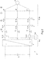
- Fig. 1 an equivalent circuit diagram of the electrical network 1 of a rail vehicle (not shown) is shown.
- the electrical network 1 comprises a converter C (see Fig. 2 ), where in Fig. 1 a resulting inductance L1_C and a resulting resistance R1_C of the converter C are shown.
- An intermediate circuit capacitor C_k is also shown.
- the electrical network 1 further comprises a permanent magnet machine M, a resulting inductance L_M and a resulting resistance R_M of the permanent magnet machine M also being shown.
- a phase line P with a first section A, a second section B and a third section C.
- a current sensor CS and an evaluation device AE are also shown.
- the current sensor CS detects a current value in a determination point BP of the phase line P.
- a current I is shown as an example.
- the evaluation device AE determines a change in current dl / dt as a function of the current value and a duration dt. This change in current is determined cyclically.
- Resulting resistances R_A, R_B, R_C of the individual sections A, B, C of phase line P are also shown.
- Resulting inductances L_A, L_B, L_C of sections A, B, C are also shown accordingly.
- a first electrical switching element S1 which can be referred to as a motor power switch, for example, is arranged along the phase line P. Also arranged along the phase line P is a further electrical switching element S2, which can be referred to, for example, as an emergency stop motor circuit breaker. An electrical connection between the converter C and the permanent magnet machine M via the phase line P can be established or interrupted by means of the switching elements S1, S2.
- the first section A here comprises at least a section of the phase line P between the determination point BP and the first electrical switching element S1.
- the second section B here comprises a section of the phase line P between the first electrical switching element S1 and the second electrical switching element S2.
- the switching elements S1, S2 are arranged in such a way that the first section A can be connected to the second section B by means of the first switching element S1. Furthermore, the second section B can be connected to the third section C by means of the second switching element S2. Motor protection switches which enable the electrical connection to be interrupted at connection points AP of the permanent magnet machine M are not shown.
- the third section C here comprises a section of the phase line P between the second electrical switching element S2 and a connection point AP of the permanent magnet machine M.
- a fourth section D is also shown, which comprises the electrical network of the permanent magnet machine M up to the connection points AP.
- a level or an amount of the current change in the phase current I can be determined in each cycle.
- the evaluation device AE also evaluates whether a current change-based criterion is met, this criterion being met if the magnitude of the current change in the phase current I in each cycle is greater than a first predetermined value or the amount of the current change threshold value SW1 (see FIG Fig. 3 ) is.
- a network fault in particular a short circuit, is detected in a machine-side subnetwork TN_M.
- the machine-side subnetwork TN_M here includes at least that part of the electrical network 1 which includes the part of the phase line P that is arranged between the determination point BP and the connection point AP of the permanent magnet machine M.
- the machine-side subnetwork TN_M further comprises at least part of the electrical network of the permanent magnet machine M.
- a converter-side subnetwork TN_C is also shown. This includes at least part of the electrical network of the converter C (not shown) and that part of the phase line P which connects the converter C and the destination point BP.
- the network error detected as described above is detected in the machine-side subnetwork TN_M.
- a level or an amount of the phase current I is determined by the evaluation device AE.
- a network fault can be detected in the machine-side subnetwork TN_M if a current value-based criterion is also met. This is fulfilled when the level of the phase current I is greater than a predetermined current value threshold value.
- At least one of the switching elements S1, S2, preferably both switching elements S1, S2, can be opened.
- a three-phase electrical network 1 of a rail vehicle (not shown) is shown schematically.
- an intermediate circuit capacitor C_k is shown, which is electrically connected to a converter C on the input side.
- the converter C is connected to a permanent magnet machine M via three phases P1, P2, P3.
- no resulting resistances and resulting inductances are shown.
- first current sensor CS_P1 for detecting a first phase current I_P1 in a first phase line P1.
- Another current sensor CS_P3 for detecting a third phase current I_P3 in a third phase line P3 is also shown.
- a second phase current I_P2 in a second phase line P2 can be determined as a function of the remaining phase currents I_P1, I_P3.
- each of the phase lines P1, P2, P3 comprises a first electrical switching element S1_P1, S1_P2, S1_P3 and a second electrical switching element S2_P1, S2_P2, S2_P3. Also shown is a subdivision of the respective phase line P1, P2, P3 into sections A, B, C. Also shown are connection points AP of the permanent magnet machine M, a fourth section D comprising an electrical network of the permanent magnet machine M. It is shown here that the first electrical switching elements S1_P1, S1_P2, S1_P3 are controlled by a control device 2, ie can be opened or closed. In this case, the first electrical switching elements S1_P1, S1_P2, S1_P3 can be controlled jointly, in particular simultaneously, by the control device 2.
- the second electrical switching elements S2_P1, S2_P2, S2_P3 are controlled by a second control device 3, i.e. can be opened or closed.
- the second electrical switching elements S2_P1, S2_P2, S2_P3 can also be controlled jointly, in particular simultaneously, by the second control device 3.
- An evaluation device AE can be used to cyclically determine an amount or an amount of a change in current of both the first phase current I_P1, the second phase current I_P2 and the third phase current I_P3.
- a network fault in a machine-side subnetwork can be detected if the previously explained current change-based criterion is met for at least one of the phase currents I_P1, I_P2, I_P3.
- At least two, but preferably all, of the first switching elements S1_P1, S1_P2, S1_P3 can be opened.
- at least two, but preferably all, of the second switching elements S1_P1, S1_P2, S1_P3 can be opened.
- the first and / or second switching elements S1_P1, S1_P2, S1_P3, S2_P1, S2_P2, S2_P3 of the phase line (s) for which the current change-based criterion is met can be opened.
- a device for monitoring the electrical network 1 can include at least the evaluation device AE. This can preferably also include the current sensors CS_P1, CS_P3.
- Fig. 3 is an exemplary relationship between the magnitude of a change in current dl / dt and a distance d of a fault location from a determination point BP (see Fig. 1 ) shown in a phase line P1, P2, P3.
- the amount of current change determined by the evaluation device AE is higher the closer the fault location is to the determination point BP.
- the magnitude of the change in current decreases exponentially with increasing distance d from the determination point BP.
- a network fault in the machine-side subnetwork TN_M (see FIG Fig. 1 and Fig. 2 ) can be detected. It can thus be detected that either in the first section A, in the second section B, in the third section C or in the fourth section D (see Fig. 1 ) there is a network error.
- the speed of the permanent magnet machine M can, for example, be reduced, in particular by partially or completely braking the rail vehicle, i.e. to a standstill.
- a fault location in the fourth section D can be detected if the magnitude of the current change is greater than the first predetermined current change threshold value SW1 and less than or equal to a second predetermined current change threshold value SW2.
- the amount of current change determined by the evaluation device AE is greater than the second predetermined current change threshold value SW2, it can be detected that a fault location is either in the first section A or in the second section B or in the third section C of the machine-side subnetwork TN_M. If the magnitude of the change in current is less than or equal to a third predetermined current change threshold value SW3, but greater than the second predetermined current change threshold value SW2, it can be detected that the fault location is in third section C.
- the fault location lies in the second section B if the magnitude of the current change is greater than the third predetermined current change threshold value SW3, but less than or equal to a fourth predetermined current change threshold value SW4.
- the fact that the fault location is in the first section A can be detected when the magnitude of the current change is greater than the fourth predetermined current change threshold value SW4.
- a fault location-dependent protective function can then be carried out. If, for example, the fault location is in the second section B, the first switching element S1 and the second switching element S2 (see FIG Fig. 1 ) can be opened. If the location is in the third section C, then, for example, the second switching element S2 can be opened and the electrical connection at the connection point AP of the permanent magnet machine M can be interrupted.
- the electrical connection at the connection point AP can be interrupted and the speed of the motor can be reduced. If the fault location is in the first section A, the first switching element S1 can be opened.
Landscapes
- Engineering & Computer Science (AREA)
- Power Engineering (AREA)
- Electric Propulsion And Braking For Vehicles (AREA)
- Control Of Electric Motors In General (AREA)
- Control Of Ac Motors In General (AREA)
Claims (8)
- Procédé de surveillance d'un réseau électrique (1) dans un véhicule sur rails, dans lequel le réseau électrique (1) comprend au moins un convertisseur de puissance (C), au moins un moteur d'entraînement (M) et au moins une première ligne de phase (P, P1) pour relier électriquement l'au moins un convertisseur de puissance (C) et l'au moins un moteur d'entraînement, dans lequel une intensité d'une variation de courant d'un premier courant de phase (I, I1) est déterminée, dans lequel une défaillance de réseau est détectée si au moins un critère basé sur la variation de courant est rempli, dans lequel le critère basé sur la variation de courant est rempli quand une intensité de la variation de courant du premier courant de phase (I , I1) est supérieure à une valeur de seuil de variation de courant (SW1) prédéterminée,
caractérisé en ce que
la défaillance de réseau est détectée dans un réseau partiel côté machine (TN_M), dans lequel un emplacement de défaillance est déterminé dans le réseau partiel côté machine (TN_M) en fonction de l'intensité de la variation de courant, dans lequel une intensité de la variation de courant se réduit au fur et à mesure que la distance entre un emplacement de défaillance dans le réseau partiel côté machine (TN_M) et un point déterminé (BP), dans lequel apparaît la variation de courant, augmente. - Procédé selon la revendication 1, caractérisé en ce que la variation de courant du premier courant de phase (I, I1) est déterminée de manière cyclique, dans lequel le critère basé sur la variation de courant est rempli si l'intensité de la variation de courant est respectivement supérieure à la valeur de seuil de variation de courant (SW1) prédéterminée pour au moins un nombre prédéterminé de cycles.
- Procédé selon l'une quelconque des revendications précédentes, caractérisé en ce qu'une intensité du premier courant de phase (I, I1) est déterminée, dans lequel une défaillance de réseau est détectée dans le réseau partiel de réseau côté machine (TN_M) si en supplément un critère basé sur la valeur de courant est rempli, dans lequel le critère basé sur la valeur de courant est rempli quand l'intensité du premier courant de phase (I, I1) est supérieure à une valeur de seuil de valeur de courant prédéterminée.
- Procédé selon l'une quelconque des revendications précédentes, caractérisé en ce que lors de la détection d'une défaillance de réseau dans la partie de réseau côté machine (TN_M), un emplacement de défaillance est déterminé dans le réseau partiel côté machine (TN_M) et une fonction de protection dépendant de l'emplacement de défaillance est exécutée, dans lequel un flux de courant à travers une portion de réseau défectueuse est réduit et/ou une vitesse de rotation du moteur d'entraînement est réduite.
- Procédé selon l'une quelconque des revendications 1 à 4, caractérisé en ce que lors de la détection d'une défaillance de réseau dans la partie de réseau côté machine (TN_M), une vitesse de rotation du moteur d'entraînement est réduite et/ou au moins la première ligne de phase (P, P1) est interrompue.
- Procédé selon l'une quelconque des revendications 1 à 5, caractérisé en ce que le réseau électrique (1) comprend trois lignes de phase (P, P1, P2, P3) pour relier électriquement l'au moins un convertisseur de puissance (C) et l'au moins un moteur d'entraînement, dans lequel une intensité d'une variation de courant de tous les courants de phase (I, I1, I2, I3) est déterminée, dans lequel une défaillance de réseau spécifique à la phase est détectée dans le réseau partiel côté machine (TN_M) si l'au moins un critère basé sur la variation de courant est rempli pour une des lignes de phase (P, P1, P2, P3).
- Dispositif de surveillance d'un réseau électrique (1) dans un véhicule sur rails, dans lequel le réseau électrique (1) comprend au moins un convertisseur de puissance (C), au moins un moteur d'entraînement et au moins une première ligne de phase (P, P1) pour relier électriquement l'au moins un convertisseur de puissance (C) et l'au moins un moteur d'entraînement, dans lequel le dispositif comprend au moins un système d'évaluation (AE) et au moins un premier système pour déterminer une intensité de la variation de courant d'un premier courant de phase (I, I1, I2, I3), dans lequel une intensité de la variation de courant du premier courant de phase (I, I1) peut être déterminée, dans lequel une défaillance de réseau peut être détectée par le système d'évaluation (AE) si au moins un critère basé sur la variation de courant est rempli, dans lequel le critère basé sur la variation de courant est rempli quand l'intensité de la variation de courant du premier courant de phase (I, I1) est supérieure à une valeur de seuil de variation de courant (SW1) prédéterminée,
caractérisé en ce que
la défaillance de réseau peut être détectée dans un réseau partiel côté machine (TN_M), dans lequel un emplacement de défaillance peut être déterminé dans le réseau partiel côté machine (TN_M) en fonction de l'intensité de la variation de courant, dans lequel une intensité de la variation de courant se réduit au fur et à mesure que la distance entre un emplacement de défaillance dans le réseau partiel côté machine (TN_M) et un point déterminé, dans lequel apparaît la variation de courant, augmente. - Véhicule sur rails comprenant un dispositif selon la revendication 7.
Applications Claiming Priority (2)
| Application Number | Priority Date | Filing Date | Title |
|---|---|---|---|
| DE102014219278.1A DE102014219278A1 (de) | 2014-09-24 | 2014-09-24 | Verfahren und Vorrichtung zur Überwachung eines elektrischen Netzwerks in einem Schienenfahrzeug sowie Schienenfahrzeug |
| PCT/EP2015/071817 WO2016046247A1 (fr) | 2014-09-24 | 2015-09-23 | Procédé et dispositif de surveillance d'un réseau électrique dans un véhicule ferroviaire et véhicule ferroviaire |
Publications (2)
| Publication Number | Publication Date |
|---|---|
| EP3198697A1 EP3198697A1 (fr) | 2017-08-02 |
| EP3198697B1 true EP3198697B1 (fr) | 2021-08-18 |
Family
ID=54260730
Family Applications (1)
| Application Number | Title | Priority Date | Filing Date |
|---|---|---|---|
| EP15775654.5A Active EP3198697B1 (fr) | 2014-09-24 | 2015-09-23 | Procédé et dispositif de surveillance d'un réseau électrique dans un véhicule ferroviaire et véhicule ferroviaire |
Country Status (7)
| Country | Link |
|---|---|
| US (1) | US10153633B2 (fr) |
| EP (1) | EP3198697B1 (fr) |
| CN (1) | CN107005041B (fr) |
| DE (1) | DE102014219278A1 (fr) |
| ES (1) | ES2891135T3 (fr) |
| RU (1) | RU2017113961A (fr) |
| WO (1) | WO2016046247A1 (fr) |
Families Citing this family (3)
| Publication number | Priority date | Publication date | Assignee | Title |
|---|---|---|---|---|
| EP3576297A1 (fr) * | 2018-05-31 | 2019-12-04 | Alstom Ferroviaria S.P.A. | Procédé de localisation de courts-circuits dans un circuit d'alimentation d'un moteur pmm |
| DE102018209582A1 (de) | 2018-06-14 | 2019-12-19 | Bombardier Transportation Gmbh | Verfahren zum Betreiben eines elektrisch angetriebenen Fahrzeugs und elektrisch angetriebenes Fahrzeug |
| CN110729708B (zh) * | 2019-09-30 | 2022-01-28 | 国电南瑞科技股份有限公司 | 基于以太网与e1通道高速铁路牵引网故障处理决策装置 |
Family Cites Families (13)
| Publication number | Priority date | Publication date | Assignee | Title |
|---|---|---|---|---|
| US4203142A (en) | 1978-07-31 | 1980-05-13 | Lee Donald E | Ground fault system and method of detection |
| DE4400234C1 (de) * | 1994-01-05 | 1995-08-03 | Elbas Elektrische Bahnsysteme | Verfahren zur Kurzschlußerkennung in Bahnnetzen |
| US5578912A (en) * | 1994-02-04 | 1996-11-26 | Alps Electric Co., Ltd. | On-car motor driving apparatus and self-diagnosing and selective driving mechanisms for the same |
| JP3704400B2 (ja) * | 1996-07-03 | 2005-10-12 | ファナック株式会社 | モータのインバータ駆動制御装置における異常診断方法 |
| JP2006311684A (ja) | 2005-04-27 | 2006-11-09 | Mitsubishi Electric Corp | 永久磁石式風力発電設備の短絡事故検出装置 |
| FR2900241B1 (fr) | 2006-04-21 | 2008-07-11 | Alstom Transport Sa | Procede de depistage d'un court-circuit resistif, systeme, module et support d'enregistrement pour ce procede |
| FR2933818B1 (fr) | 2008-07-10 | 2010-09-03 | Alstom Transport Sa | Systeme d'alimentation electrique pour moteur triphase a aimants permanents. |
| DE102011012314A1 (de) * | 2011-02-25 | 2012-08-30 | Volkswagen Aktiengesellschaft | Verfahren und Vorrichtung zur Steuerung mindestens eines Phasenstromes |
| CN103688434B (zh) * | 2011-07-21 | 2017-03-22 | 西门子公司 | 单侧馈电的供电线路中的故障识别和故障定位 |
| JP5951237B2 (ja) * | 2011-11-21 | 2016-07-13 | 株式会社東芝 | 直流き電保護継電装置 |
| DE102014207171A1 (de) * | 2014-04-15 | 2015-10-15 | Robert Bosch Gmbh | Verfahren und Vorrichtung zum Ermitteln eines Innenwiderstandes eines Versorgungsnetzes zur Energieversorgung einer Personenschutzeinrichtung eines Fahrzeugs |
| US9960723B2 (en) * | 2016-06-06 | 2018-05-01 | Rockwell Automation Technologies, Inc. | Motor drive with resonance detection and impedance computation |
| US11171796B2 (en) * | 2016-06-23 | 2021-11-09 | Hewlett Packard Enterprise Development Lp | Managing multicast scaling |
-
2014
- 2014-09-24 DE DE102014219278.1A patent/DE102014219278A1/de not_active Withdrawn
-
2015
- 2015-09-23 EP EP15775654.5A patent/EP3198697B1/fr active Active
- 2015-09-23 CN CN201580051348.6A patent/CN107005041B/zh active Active
- 2015-09-23 ES ES15775654T patent/ES2891135T3/es active Active
- 2015-09-23 RU RU2017113961A patent/RU2017113961A/ru not_active Application Discontinuation
- 2015-09-23 US US15/513,791 patent/US10153633B2/en active Active
- 2015-09-23 WO PCT/EP2015/071817 patent/WO2016046247A1/fr not_active Ceased
Also Published As
| Publication number | Publication date |
|---|---|
| CN107005041A (zh) | 2017-08-01 |
| DE102014219278A1 (de) | 2016-03-24 |
| EP3198697A1 (fr) | 2017-08-02 |
| WO2016046247A1 (fr) | 2016-03-31 |
| US10153633B2 (en) | 2018-12-11 |
| ES2891135T3 (es) | 2022-01-26 |
| CN107005041B (zh) | 2019-06-21 |
| RU2017113961A (ru) | 2018-10-24 |
| DE102014219278A8 (de) | 2016-06-30 |
| US20180115149A1 (en) | 2018-04-26 |
Similar Documents
| Publication | Publication Date | Title |
|---|---|---|
| EP2745394B1 (fr) | Circuit d'états de fonctionnement pour un onduleur et procédé de réglage des états de fonctionnement d'un onduleur | |
| EP3449557B1 (fr) | Dispositif onduleur, système d'entraînement électrique et procédé de décharge d'un condensateur de circuit intermédiaire dans un dispositif onduleur | |
| EP2810366B1 (fr) | Procédé et dispositif de surveillance du système de commande de court-circuit d'un moteur triphasé | |
| DE102016114445B4 (de) | Dreiphasen-Wechselrichtersystem | |
| EP2715939B1 (fr) | Procédé et dispositif d'exploitation d'un étage final de puissance | |
| DE102017128005A1 (de) | Detektion und abschwächung von umrichterfehlern bei motoren von lenkungssystemen | |
| WO2017129285A1 (fr) | Procédé de détection d'une défaillance dans un groupe générateur | |
| EP3058652B1 (fr) | Appareil de commande à débranchement de sécurité | |
| DE102010062334A1 (de) | Verfahren und Vorrichtung zum Betreiben einer durch einen Wechselrichter gesteuerten elektrischen Maschine im Falle einer Störung | |
| EP3198697B1 (fr) | Procédé et dispositif de surveillance d'un réseau électrique dans un véhicule ferroviaire et véhicule ferroviaire | |
| DE102019217836A1 (de) | Verfahren zur Betriebssteuerung einer elektrischen Fahrzeugantriebseinheit mit zwei Steuerungen | |
| EP3188924B1 (fr) | Procédé et dispositif de surveillance d'un réseau électrique dans un véhicule ferroviaire et véhicule ferroviaire | |
| DE102014208747A1 (de) | Verfahren zum Wechsel eines Betriebszustands einer elektrischen Maschine und Vorrichtung zum Betriebszustandswechsel einer elektrischen Maschine | |
| WO2017089065A1 (fr) | Procédé de détection d'une défaillance dans un groupe générateur | |
| DE102017211219A1 (de) | Verfahren und Vorrichtung zum Betreiben einer elektrischen Maschine, insbesondere eines Lenkunterstützungsantriebs | |
| EP2774266B1 (fr) | Procédé et dispositif pour faire fonctionner une machine électrique à commutation électronique en cas de défaillance | |
| DE102012208631A1 (de) | Verfahren und Vorrichtung zum Betrieb eines bürstenlosen Motors | |
| EP4256691A1 (fr) | Procédé pour faire fonctionner une machine électrique, dispositif pour faire fonctionner une machine électrique et système d'entraînement électrique | |
| DE102015201543A1 (de) | Ansteuerungsverfahren zur Stillstandssicherung einer elektrischen Maschine | |
| DE102016204854A1 (de) | Ermittlung eines Kurzschlussstroms in den Phasen einer mittels eines Wechselrichters angesteuerten E-Maschine | |
| DE102015003446A1 (de) | Versorgung eines Kraftfahrzeugs mit Spannungsprüfung | |
| EP2654155B1 (fr) | Convertisseur de courant, tout comme procédé destiné au fonctionnement d'un convertisseur de courant | |
| EP3893386B1 (fr) | Appareil de commande, circuit de commande et véhicule automobile | |
| WO2011157470A1 (fr) | Montage pour déterminer une variation de tension de potentiels de conducteur dans un réseau électrique non mis à la terre | |
| DE102015000086A1 (de) | Verfahren zur Drehmomentüberwachung und Umrichter |
Legal Events
| Date | Code | Title | Description |
|---|---|---|---|
| STAA | Information on the status of an ep patent application or granted ep patent |
Free format text: STATUS: THE INTERNATIONAL PUBLICATION HAS BEEN MADE |
|
| PUAI | Public reference made under article 153(3) epc to a published international application that has entered the european phase |
Free format text: ORIGINAL CODE: 0009012 |
|
| STAA | Information on the status of an ep patent application or granted ep patent |
Free format text: STATUS: REQUEST FOR EXAMINATION WAS MADE |
|
| 17P | Request for examination filed |
Effective date: 20170306 |
|
| AK | Designated contracting states |
Kind code of ref document: A1 Designated state(s): AL AT BE BG CH CY CZ DE DK EE ES FI FR GB GR HR HU IE IS IT LI LT LU LV MC MK MT NL NO PL PT RO RS SE SI SK SM TR |
|
| AX | Request for extension of the european patent |
Extension state: BA ME |
|
| DAV | Request for validation of the european patent (deleted) | ||
| DAX | Request for extension of the european patent (deleted) | ||
| GRAP | Despatch of communication of intention to grant a patent |
Free format text: ORIGINAL CODE: EPIDOSNIGR1 |
|
| STAA | Information on the status of an ep patent application or granted ep patent |
Free format text: STATUS: GRANT OF PATENT IS INTENDED |
|
| INTG | Intention to grant announced |
Effective date: 20210325 |
|
| GRAS | Grant fee paid |
Free format text: ORIGINAL CODE: EPIDOSNIGR3 |
|
| GRAA | (expected) grant |
Free format text: ORIGINAL CODE: 0009210 |
|
| STAA | Information on the status of an ep patent application or granted ep patent |
Free format text: STATUS: THE PATENT HAS BEEN GRANTED |
|
| AK | Designated contracting states |
Kind code of ref document: B1 Designated state(s): AL AT BE BG CH CY CZ DE DK EE ES FI FR GB GR HR HU IE IS IT LI LT LU LV MC MK MT NL NO PL PT RO RS SE SI SK SM TR |
|
| REG | Reference to a national code |
Ref country code: GB Ref legal event code: FG4D Free format text: NOT ENGLISH |
|
| REG | Reference to a national code |
Ref country code: CH Ref legal event code: EP |
|
| REG | Reference to a national code |
Ref country code: DE Ref legal event code: R096 Ref document number: 502015015080 Country of ref document: DE |
|
| RAP4 | Party data changed (patent owner data changed or rights of a patent transferred) |
Owner name: BOMBARDIER TRANSPORTATION GMBH |
|
| REG | Reference to a national code |
Ref country code: IE Ref legal event code: FG4D Free format text: LANGUAGE OF EP DOCUMENT: GERMAN Ref country code: AT Ref legal event code: REF Ref document number: 1422488 Country of ref document: AT Kind code of ref document: T Effective date: 20210915 |
|
| REG | Reference to a national code |
Ref country code: LT Ref legal event code: MG9D |
|
| REG | Reference to a national code |
Ref country code: NL Ref legal event code: MP Effective date: 20210818 |
|
| REG | Reference to a national code |
Ref country code: ES Ref legal event code: FG2A Ref document number: 2891135 Country of ref document: ES Kind code of ref document: T3 Effective date: 20220126 |
|
| PG25 | Lapsed in a contracting state [announced via postgrant information from national office to epo] |
Ref country code: RS Free format text: LAPSE BECAUSE OF FAILURE TO SUBMIT A TRANSLATION OF THE DESCRIPTION OR TO PAY THE FEE WITHIN THE PRESCRIBED TIME-LIMIT Effective date: 20210818 Ref country code: SE Free format text: LAPSE BECAUSE OF FAILURE TO SUBMIT A TRANSLATION OF THE DESCRIPTION OR TO PAY THE FEE WITHIN THE PRESCRIBED TIME-LIMIT Effective date: 20210818 Ref country code: HR Free format text: LAPSE BECAUSE OF FAILURE TO SUBMIT A TRANSLATION OF THE DESCRIPTION OR TO PAY THE FEE WITHIN THE PRESCRIBED TIME-LIMIT Effective date: 20210818 Ref country code: PT Free format text: LAPSE BECAUSE OF FAILURE TO SUBMIT A TRANSLATION OF THE DESCRIPTION OR TO PAY THE FEE WITHIN THE PRESCRIBED TIME-LIMIT Effective date: 20211220 Ref country code: NO Free format text: LAPSE BECAUSE OF FAILURE TO SUBMIT A TRANSLATION OF THE DESCRIPTION OR TO PAY THE FEE WITHIN THE PRESCRIBED TIME-LIMIT Effective date: 20211118 Ref country code: FI Free format text: LAPSE BECAUSE OF FAILURE TO SUBMIT A TRANSLATION OF THE DESCRIPTION OR TO PAY THE FEE WITHIN THE PRESCRIBED TIME-LIMIT Effective date: 20210818 Ref country code: LT Free format text: LAPSE BECAUSE OF FAILURE TO SUBMIT A TRANSLATION OF THE DESCRIPTION OR TO PAY THE FEE WITHIN THE PRESCRIBED TIME-LIMIT Effective date: 20210818 Ref country code: BG Free format text: LAPSE BECAUSE OF FAILURE TO SUBMIT A TRANSLATION OF THE DESCRIPTION OR TO PAY THE FEE WITHIN THE PRESCRIBED TIME-LIMIT Effective date: 20211118 |
|
| PG25 | Lapsed in a contracting state [announced via postgrant information from national office to epo] |
Ref country code: PL Free format text: LAPSE BECAUSE OF FAILURE TO SUBMIT A TRANSLATION OF THE DESCRIPTION OR TO PAY THE FEE WITHIN THE PRESCRIBED TIME-LIMIT Effective date: 20210818 Ref country code: LV Free format text: LAPSE BECAUSE OF FAILURE TO SUBMIT A TRANSLATION OF THE DESCRIPTION OR TO PAY THE FEE WITHIN THE PRESCRIBED TIME-LIMIT Effective date: 20210818 Ref country code: GR Free format text: LAPSE BECAUSE OF FAILURE TO SUBMIT A TRANSLATION OF THE DESCRIPTION OR TO PAY THE FEE WITHIN THE PRESCRIBED TIME-LIMIT Effective date: 20211119 |
|
| PG25 | Lapsed in a contracting state [announced via postgrant information from national office to epo] |
Ref country code: NL Free format text: LAPSE BECAUSE OF FAILURE TO SUBMIT A TRANSLATION OF THE DESCRIPTION OR TO PAY THE FEE WITHIN THE PRESCRIBED TIME-LIMIT Effective date: 20210818 |
|
| PG25 | Lapsed in a contracting state [announced via postgrant information from national office to epo] |
Ref country code: DK Free format text: LAPSE BECAUSE OF FAILURE TO SUBMIT A TRANSLATION OF THE DESCRIPTION OR TO PAY THE FEE WITHIN THE PRESCRIBED TIME-LIMIT Effective date: 20210818 |
|
| REG | Reference to a national code |
Ref country code: DE Ref legal event code: R097 Ref document number: 502015015080 Country of ref document: DE |
|
| REG | Reference to a national code |
Ref country code: BE Ref legal event code: MM Effective date: 20210930 |
|
| PG25 | Lapsed in a contracting state [announced via postgrant information from national office to epo] |
Ref country code: SM Free format text: LAPSE BECAUSE OF FAILURE TO SUBMIT A TRANSLATION OF THE DESCRIPTION OR TO PAY THE FEE WITHIN THE PRESCRIBED TIME-LIMIT Effective date: 20210818 Ref country code: SK Free format text: LAPSE BECAUSE OF FAILURE TO SUBMIT A TRANSLATION OF THE DESCRIPTION OR TO PAY THE FEE WITHIN THE PRESCRIBED TIME-LIMIT Effective date: 20210818 Ref country code: RO Free format text: LAPSE BECAUSE OF FAILURE TO SUBMIT A TRANSLATION OF THE DESCRIPTION OR TO PAY THE FEE WITHIN THE PRESCRIBED TIME-LIMIT Effective date: 20210818 Ref country code: MC Free format text: LAPSE BECAUSE OF FAILURE TO SUBMIT A TRANSLATION OF THE DESCRIPTION OR TO PAY THE FEE WITHIN THE PRESCRIBED TIME-LIMIT Effective date: 20210818 Ref country code: EE Free format text: LAPSE BECAUSE OF FAILURE TO SUBMIT A TRANSLATION OF THE DESCRIPTION OR TO PAY THE FEE WITHIN THE PRESCRIBED TIME-LIMIT Effective date: 20210818 Ref country code: CZ Free format text: LAPSE BECAUSE OF FAILURE TO SUBMIT A TRANSLATION OF THE DESCRIPTION OR TO PAY THE FEE WITHIN THE PRESCRIBED TIME-LIMIT Effective date: 20210818 Ref country code: AL Free format text: LAPSE BECAUSE OF FAILURE TO SUBMIT A TRANSLATION OF THE DESCRIPTION OR TO PAY THE FEE WITHIN THE PRESCRIBED TIME-LIMIT Effective date: 20210818 |
|
| PLBE | No opposition filed within time limit |
Free format text: ORIGINAL CODE: 0009261 |
|
| STAA | Information on the status of an ep patent application or granted ep patent |
Free format text: STATUS: NO OPPOSITION FILED WITHIN TIME LIMIT |
|
| 26N | No opposition filed |
Effective date: 20220519 |
|
| PG25 | Lapsed in a contracting state [announced via postgrant information from national office to epo] |
Ref country code: LU Free format text: LAPSE BECAUSE OF NON-PAYMENT OF DUE FEES Effective date: 20210923 Ref country code: IT Free format text: LAPSE BECAUSE OF FAILURE TO SUBMIT A TRANSLATION OF THE DESCRIPTION OR TO PAY THE FEE WITHIN THE PRESCRIBED TIME-LIMIT Effective date: 20210818 Ref country code: IE Free format text: LAPSE BECAUSE OF NON-PAYMENT OF DUE FEES Effective date: 20210923 Ref country code: BE Free format text: LAPSE BECAUSE OF NON-PAYMENT OF DUE FEES Effective date: 20210930 |
|
| PG25 | Lapsed in a contracting state [announced via postgrant information from national office to epo] |
Ref country code: SI Free format text: LAPSE BECAUSE OF FAILURE TO SUBMIT A TRANSLATION OF THE DESCRIPTION OR TO PAY THE FEE WITHIN THE PRESCRIBED TIME-LIMIT Effective date: 20210818 |
|
| PG25 | Lapsed in a contracting state [announced via postgrant information from national office to epo] |
Ref country code: HU Free format text: LAPSE BECAUSE OF FAILURE TO SUBMIT A TRANSLATION OF THE DESCRIPTION OR TO PAY THE FEE WITHIN THE PRESCRIBED TIME-LIMIT; INVALID AB INITIO Effective date: 20150923 |
|
| PG25 | Lapsed in a contracting state [announced via postgrant information from national office to epo] |
Ref country code: CY Free format text: LAPSE BECAUSE OF FAILURE TO SUBMIT A TRANSLATION OF THE DESCRIPTION OR TO PAY THE FEE WITHIN THE PRESCRIBED TIME-LIMIT Effective date: 20210818 |
|
| P01 | Opt-out of the competence of the unified patent court (upc) registered |
Effective date: 20230822 |
|
| PG25 | Lapsed in a contracting state [announced via postgrant information from national office to epo] |
Ref country code: MK Free format text: LAPSE BECAUSE OF FAILURE TO SUBMIT A TRANSLATION OF THE DESCRIPTION OR TO PAY THE FEE WITHIN THE PRESCRIBED TIME-LIMIT Effective date: 20210818 |
|
| PG25 | Lapsed in a contracting state [announced via postgrant information from national office to epo] |
Ref country code: MT Free format text: LAPSE BECAUSE OF FAILURE TO SUBMIT A TRANSLATION OF THE DESCRIPTION OR TO PAY THE FEE WITHIN THE PRESCRIBED TIME-LIMIT Effective date: 20210818 |
|
| REG | Reference to a national code |
Ref country code: CH Ref legal event code: U11 Free format text: ST27 STATUS EVENT CODE: U-0-0-U10-U11 (AS PROVIDED BY THE NATIONAL OFFICE) Effective date: 20251001 |
|
| PGFP | Annual fee paid to national office [announced via postgrant information from national office to epo] |
Ref country code: DE Payment date: 20250919 Year of fee payment: 11 |
|
| PGFP | Annual fee paid to national office [announced via postgrant information from national office to epo] |
Ref country code: GB Payment date: 20250919 Year of fee payment: 11 |
|
| PGFP | Annual fee paid to national office [announced via postgrant information from national office to epo] |
Ref country code: FR Payment date: 20250922 Year of fee payment: 11 Ref country code: AT Payment date: 20250919 Year of fee payment: 11 |
|
| PG25 | Lapsed in a contracting state [announced via postgrant information from national office to epo] |
Ref country code: TR Free format text: LAPSE BECAUSE OF FAILURE TO SUBMIT A TRANSLATION OF THE DESCRIPTION OR TO PAY THE FEE WITHIN THE PRESCRIBED TIME-LIMIT Effective date: 20210818 |
|
| PGFP | Annual fee paid to national office [announced via postgrant information from national office to epo] |
Ref country code: CH Payment date: 20251001 Year of fee payment: 11 |
|
| PGFP | Annual fee paid to national office [announced via postgrant information from national office to epo] |
Ref country code: ES Payment date: 20251028 Year of fee payment: 11 |