EP3198699B1 - Système et procédé énergétique hybride - Google Patents
Système et procédé énergétique hybride Download PDFInfo
- Publication number
- EP3198699B1 EP3198699B1 EP15843176.7A EP15843176A EP3198699B1 EP 3198699 B1 EP3198699 B1 EP 3198699B1 EP 15843176 A EP15843176 A EP 15843176A EP 3198699 B1 EP3198699 B1 EP 3198699B1
- Authority
- EP
- European Patent Office
- Prior art keywords
- gtg
- storage device
- output
- energy system
- hybrid energy
- Prior art date
- Legal status (The legal status is an assumption and is not a legal conclusion. Google has not performed a legal analysis and makes no representation as to the accuracy of the status listed.)
- Active
Links
Images


Classifications
-
- H—ELECTRICITY
- H02—GENERATION; CONVERSION OR DISTRIBUTION OF ELECTRIC POWER
- H02J—ELECTRIC POWER NETWORKS; CIRCUIT ARRANGEMENTS OR SYSTEMS FOR SUPPLYING OR DISTRIBUTING ELECTRIC POWER; SYSTEMS FOR STORING ELECTRIC ENERGY
- H02J3/00—Circuit arrangements for AC mains or AC distribution networks
- H02J3/28—Arrangements for balancing of the load in networks by storage of energy
- H02J3/32—Arrangements for balancing of the load in networks by storage of energy using batteries or super capacitors with converting means
-
- H—ELECTRICITY
- H02—GENERATION; CONVERSION OR DISTRIBUTION OF ELECTRIC POWER
- H02J—ELECTRIC POWER NETWORKS; CIRCUIT ARRANGEMENTS OR SYSTEMS FOR SUPPLYING OR DISTRIBUTING ELECTRIC POWER; SYSTEMS FOR STORING ELECTRIC ENERGY
- H02J3/00—Circuit arrangements for AC mains or AC distribution networks
- H02J3/008—Circuit arrangements for power supply or distribution technologies responsive to energy trading
-
- H—ELECTRICITY
- H02—GENERATION; CONVERSION OR DISTRIBUTION OF ELECTRIC POWER
- H02J—ELECTRIC POWER NETWORKS; CIRCUIT ARRANGEMENTS OR SYSTEMS FOR SUPPLYING OR DISTRIBUTING ELECTRIC POWER; SYSTEMS FOR STORING ELECTRIC ENERGY
- H02J3/00—Circuit arrangements for AC mains or AC distribution networks
- H02J3/38—Arrangements for feeding a single network from two or more generators or sources in parallel; Arrangements for feeding already energised networks from additional generators or sources in parallel
- H02J3/381—Dispersed generators
-
- H—ELECTRICITY
- H02—GENERATION; CONVERSION OR DISTRIBUTION OF ELECTRIC POWER
- H02J—ELECTRIC POWER NETWORKS; CIRCUIT ARRANGEMENTS OR SYSTEMS FOR SUPPLYING OR DISTRIBUTING ELECTRIC POWER; SYSTEMS FOR STORING ELECTRIC ENERGY
- H02J3/00—Circuit arrangements for AC mains or AC distribution networks
- H02J3/38—Arrangements for feeding a single network from two or more generators or sources in parallel; Arrangements for feeding already energised networks from additional generators or sources in parallel
- H02J3/46—Controlling the sharing of generated power between the generators, sources or networks
-
- H—ELECTRICITY
- H02—GENERATION; CONVERSION OR DISTRIBUTION OF ELECTRIC POWER
- H02J—ELECTRIC POWER NETWORKS; CIRCUIT ARRANGEMENTS OR SYSTEMS FOR SUPPLYING OR DISTRIBUTING ELECTRIC POWER; SYSTEMS FOR STORING ELECTRIC ENERGY
- H02J2101/00—Supply or distribution of decentralised, dispersed or local electric power generation
- H02J2101/10—Dispersed power generation using fossil fuels, e.g. diesel generators
-
- Y—GENERAL TAGGING OF NEW TECHNOLOGICAL DEVELOPMENTS; GENERAL TAGGING OF CROSS-SECTIONAL TECHNOLOGIES SPANNING OVER SEVERAL SECTIONS OF THE IPC; TECHNICAL SUBJECTS COVERED BY FORMER USPC CROSS-REFERENCE ART COLLECTIONS [XRACs] AND DIGESTS
- Y04—INFORMATION OR COMMUNICATION TECHNOLOGIES HAVING AN IMPACT ON OTHER TECHNOLOGY AREAS
- Y04S—SYSTEMS INTEGRATING TECHNOLOGIES RELATED TO POWER NETWORK OPERATION, COMMUNICATION OR INFORMATION TECHNOLOGIES FOR IMPROVING THE ELECTRICAL POWER GENERATION, TRANSMISSION, DISTRIBUTION, MANAGEMENT OR USAGE, i.e. SMART GRIDS
- Y04S50/00—Market activities related to the operation of systems integrating technologies related to power network operation or related to communication or information technologies
- Y04S50/10—Energy trading, including energy flowing from end-user application to grid
Definitions
- Energy facilities are designed to provide energy to an electric grid in a reliable manner.
- an energy facility includes a gas fired generation system, such as a gas turbine generator (GTG), configured to provide energy to the electric grid while maintaining the frequency and voltage of the electric grid within acceptable limits, such as limits set by a government body, a regulatory body, transmission grid operations, or an energy facility.
- GTG gas turbine generator
- Electric grid demands change depending on a number of factors including weather, market demands, and other reliability driven events.
- the energy facility is typically designed to ramp up, including starting, or ramp down in response to these factors.
- One example of an energy facility includes a combined cycle gas turbine (CCGT) configured to remain on-line a substantial majority of the time in order to respond to the electric grid reliability factors.
- CCGT combined cycle gas turbine
- a problem to be solved can include reducing response times of a GTG, such as starting, ramping up, or ramping down, to an electric grid reliability factor.
- a GTG such as starting, ramping up, or ramping down
- An energy facility includes a simple cycle GTG that is most commonly configured to be in stand-by state, ready to start and operate only when called upon, resulting in a lesser response capability to electric grid reliability factors.
- Energy facilities are typically designed to meet some combination of energy and electric grid reliability needs. Tradeoffs are typically made between one or more of size, amount of energy that can be produced, efficiency, time to start, rate of capability to ramp output up or down, ability to operate at low power output levels relative to maximum output levels, and ability to provide products that support reliability, such as ancillary services and reserves.
- Ancillary services typically include operating reserves that are set aside for specific types of reliability events including, but not limited to:
- the present subject matter can provide a solution to this problem, such as by a hybrid energy system that aggregates and integrates a storage system, such as a battery and a GTG, to combine the features of each into a responsive system.
- a hybrid energy system that aggregates and integrates a storage system, such as a battery and a GTG, to combine the features of each into a responsive system.
- the present subject matter provides hybrid energy systems configured to be responsive, so as to provide higher quality reserves by at least one of speed, rate, magnitude, and duration of the response a to transient event.
- the present subject matter economically reduces response times of a GTG.
- Economically reducing response times includes at least one of reducing the overall start-up time or ramp time to the desired load, reducing the time to respond to a frequency disturbance, as described herein, and reducing the production of pollutants during start-up or ramping, resulting in higher quality reserves.
- the present subject matter includes a battery having substantially immediate discharge capability and a GTG that can rapidly start and supplement the power output of the battery in the matter desired by electric grid operators.
- the present subject matter can provide a solution to this problem, such as by a hybrid energy system having a GTG configured to have a fast-start, fast ramp capability in combination with a substantially immediate discharge capability from a storage device, such as a battery. Such examples provide the benefit of reducing the time the hybrid energy system responds to a change in electric grid demand.
- the present inventors have further recognized that another problem to be solved can include reducing an amount of pollutants produced by an energy facility (such as a CCGT) remaining on-line to respond to electric grid demands.
- the present subject matter provides a solution to this problem, with a hybrid energy system that includes a storage system, such as a battery, that is synchronized and ready to respond to electric grid reliability factors, ramp up, and provide substantially immediate energy for a limited period of time and a GTG in a stand-by state (e.g., off-line but substantially immediately ready to start) which significantly reduces or eliminates the production of pollutants when the GTG is not designated to provide energy to the electric grid.
- An off-line GTG is considered to be a GTG in a non-power producing state. Benefits of such an example include staging the GTG for a fast-start response to an electric grid demand while reducing or eliminating the pollutant profile of the hybrid energy system when not providing energy to the electric grid.
- the present inventors have further recognized that another problem to be solved can include reducing the cost of providing reliability and energy services produced by an energy facility.
- Hydro-carbon based energy such as burning or combusting of natural gas
- the present subject matter in one example, can provide a solution to this problem, such as by leveraging market shifts to store energy in a storage device configured to substantially immediately discharge the energy to aid in the fast-start capability of the GTG, as well as provide energy to the electric grid in response to electric grid demands.
- the present subject matter can provide a solution to this problem, such as by remaining off-line so as to not produce energy when it is non-economical.
- the present invention provides a hybrid energy system, as claimed in claim 1.
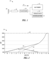
- Figure 1 shows one example of a block diagram of a hybrid energy system 10, including a generator step-up transformer 16, a GTG 12, and a storage device 14 that can be operated in accordance with the claimed invention.
- the step-up transformer 16 is configured, in an example, to convert the output of the GTG 12, the storage device 14, or both, to a higher voltage prior to being provided to an electric grid 20, where electric grid impedance is represented by block 18.
- FIG. 1 shows only one GTG 12 and one storage device 14, examples are not so limited.
- the hybrid energy system 10 can include one or more GTG 12 coupled to one or more storage device 14.
- the GTG 12 can be coupled to a plurality of the storage devices 14 or a plurality of the GTGs 12 can be coupled to a plurality of the storage devices 14, such as an energy storage bank.
- the storage device 14 is coupled to the GTG 12 and each are electrically co-located on a low-side 22 of the generator step-up transformer 16.
- the electrical co-location of the GTG 12 and the storage device 14 permits the hybrid energy system 10 to be operated as either a single generation or non-generation resource (e.g., storage) with an operating range from the full negative capacity of the one or more storage device to the combined positive capacity of the storage device and the GTG.
- electrically co-locating the GTG 12 and the storage device 14 allows for the faster responding inverter-rectifier 15 of the storage device 14 to aid the GTG response time in the event of electric grid frequency transients.
- the same electrical co-location allows the inverter-rectifier 15 ability to ride through transients in electric grid voltages provided that the GTG 12 is on line.
- the system 10 is located in multiple geographic locations, such that the GTG 12 can be separated from storage device 14. That is, the footprint of the hybrid energy facility is not limited to a single contiguous location, provided that the GTG 12 and the storage device 14 are electrically co-located at the same point on the electric grid 20 (e.g., the low side 22 of the step up transformer 16).
- the GTG 12 is configured to provide a power output, including up to a full-load power output.
- the GTG 12 includes a turbine, such as an aero-derivative or heavy duty gas turbine having the full-load power output anywhere from about 10 MW to about 350 MW or more.
- the GTG 12, in an example, is configured for a fast start, such as about 20 minutes or less, about 10 minutes or less, about 5 minutes or less, or about 2 minutes or less.
- Starting the GTG 12 includes from the stand-by state (e.g., off-line but substantially immediately ready to start) to a desired load of the GTG, including up to full-load power output.
- Off-line includes, in an example, a non-power producing state of a GTG.
- the stand-by state of the GTG 12 includes the GTG 12 off-line, but substantially immediately ready to start.
- the GTG 12 includes an auto-start feature configured to start the GTG 12 in response to a frequency disturbance event. That is, in an example the hybrid energy system 10 is configured to provide the GTG 12 droop-like capability when off-line in response to a frequency disturbance event, such as a transient or decay in frequency. This example also allows for the inverter-rectifier 15 of the storage device to supply voltage support with the GTG 12 in the stand-by state.
- the GTG 12 can include a clutch between the gas turbine and the generator, so as to provide substantially synchronous condensing. Such a configuration permits the system 10 to provide a substantially continuous and a substantially immediate response to electric grid transient voltage events, which can be accomplished without burning fuel or creating combustion emissions.
- the storage device 14 is configured to store energy.
- the storage device 14 includes a battery, such as a fast acting battery system, including an inverter-rectifier 15 to convert direct current (DC) energy being discharged from the storage device 14 to alternating current (AC) energy required by the electric grid 20 or AC energy being produced from either the electric grid 20 or the GTG 12 into DC energy stored in the storage device 14.
- the inverter-rectifier 15 is, but is not limited to, a four quadrant inverter.
- the storage device 14 is configured to respond or provide power (e.g., at least a portion of the stored energy) in about 60 seconds or less, about 30 seconds or less, about 10 seconds or less, about 5 seconds or less, about 2 seconds or less, 1.0 seconds or less, 0.5 seconds or less, or 0.1 seconds or less.
- the storage device 14 and associated inverter-rectifier is configured to receive (e.g., charge) and provide (e.g., discharge) energy.
- the storage device 14 is configured to be charged by the electric grid 20, such as when electric grid market costs are lower than the cost of producing energy with the GTG 12 (e.g., the GTG charging cost).
- the grid market cost is at least one of the environmental, monetary, and other costs associated with obtaining power from the electric grid 20 and the GTG charging cost is at least one of the environmental, monetary, and other costs associated with producing power at a set fuel cost and heat rate of the GTG.
- the storage device 14 is configured to be charged by the GTG 12 when the electric grid market costscost are more expensive than the cost of producing energy with the GTG 12.
- both the electric grid 20 and the GTG 12 can be used to charge the storage device 14.
- a portion or all of the GTG 12 output is converted to DC and delivered to a DC bus of the storage device 14 and the inverter-rectifier 15 to allow for further improvement in the primary frequency response, as described herein.
- Primary frequency response includes, for example, a response within about 30 seconds of the event that is meant to arrest a frequency disturbance.
- the GTG 12 includes, in an example, frequency response auto start capability, such that when the GTG 12 is in the stand-by state the output of the storage device 14 is substantially immediately increased and the GTG 12 auto starts in the event of an electric grid frequency decay or transient.
- the hybrid energy facility 10 includes a waste heat recovery generator.
- the waste heat recovery generator in an example, is based upon the Organic Rankine Cycle and substantially all output is converted to DC and flows to the DC bus of the storage device inverter-rectifier 15.
- the storage energy can be any capacity as long as the storage device 14 is capable of maintaining and providing the minimum stored energy necessary to provide primary frequency response during the time period while the GTG 12 is started and ramped to a desired load, such as an operator load set-point, up to and including full-load.
- the storage device 14 has an energy storage capacity of at least about 5% of the full-load power output up to about 100% of the full-load power output of the GTG 12.
- the storage device 14, in an example includes a plurality of inverter-rectifier 15 having at least 10% of the full-load power output of the GTG 12.
- the storage device 14 has an energy storage capacity approximately equal to or greater than the full-load power output of the GTG 12. That is, the storage device 14 at least has, in an example, approximately the same immediate power discharge capability as the GTG 12 when started and fully loaded. As described herein, the storage device 14 provides a short-term substitution of the GTG 12 full generation capacity. In an example, the stored energy capacity of the storage device 14 is at least about 30 minutes, about 1 hour, about 1.5 hours, about 2 hours, or about 4 hours or longer of power discharge at or beyond the full-load power output of the GTG 12.
- the hybrid energy system 10 is configured to use the storage device 14 to enhance the operational characteristics of the GTG 12.
- the stored energy capacity of the storage device 14 is used as spinning reserve and is used to provide initial primary frequency response while starting the GTG 14 from the stand-by state up to a desired load output of the hybrid energy system (e.g., operator load set-point), such as up to and including full-load power output.
- stand-by state includes a non-fuel burning mode, in which little fuel to no fuel is combusted.
- the GTG 12 is configured to remain in the stand-by state (e.g., off-line, but ready to substantially immediately start).
- the storage device 14 remains on-line and primary transient protection is provided by the stored energy and inverter-rectifier 15 of the storage device 14.
- the hybrid energy system 10 is configured to start the GTG 12 from the stand-by state to the desired load output, such as the full-load power output, in about 20 minutes or less, about 10 minutes or less, about 5 minutes or less, or in a about 2 minutes or less.
- the stored energy of the storage device 14 is used for transient protection, such that the GTG 12 starts, such as substantially instantaneously and at least a portion of a stored energy of the storage device 14 is transferred to the electric grid.
- the gas fired generator can be started and loaded without the use of the storage device 14.
- the storage output of the storage device 14 does not need to be additive to the GTG 12 output, but rather provides (e.g., substantially instantaneously) output until the GTG 12 can deliver the necessary output to provide a substantially similar ramp curve as the GTG 12 alone, as described herein. That is, the storage device 14 is slaved to a total output of the hybrid energy system 10 such that the storage device 14 discharges the difference between the desired expected output if the GTG 12 was initially synchronized and the actual GTG output, on a net basis.
- the EGT configuration enhances the GTG 12 such that the hybrid energy system is operated in a smooth, continuous fashion with a single monotonically increasing energy supply curve.
- the GTG 12 is configured to operate at a minimum power output of less than about 5%, less than about 3%, or less than about 1% of the full-load power output of the GTG 12.
- the minimum power output is the minimum output at which the GTG 12 can stably operate.
- the storage device 14 has a stored energy capacity of at least about 5% of the full-load power output up to about 100% of the full-load power output of the GTG.
- the stored energy of the storage device 14 is used for transient protection, such that the GTG 12 ramps, such as substantially instantaneously and at least a portion of a stored energy of the storage device 14 is transferred to the electric grid.
- the gas fired generator can be started and loaded without the use of the storage device 14.
- FIG. 2 shows a plot 30 of a hybrid energy system start profile in an embodiment according to the claimed invention.
- the values represented in FIG. 2 are merely for example purposes and are not limiting.
- FIG. 2 illustrates the start of the GTG (12, FIG. 1 ) and the subsequent ramping of the GTG in an EGT system configuration.
- the y-axis represents power output in megawatts (MW) and the x-axis representing elapsed time in minutes.
- MW megawatts
- the hybrid energy system plotted in plot 20 includes a storage device with an energy storage capacity of at least about 10% of the full-load power output of the GTG. Further in the example plotted in FIG. 2 , the storage device includes an inverter-rectifier having at least 20% of the full-load power output of the GTG 12.
- the hybrid energy system (10, FIG. 1 ) receives a command, such as detection of a transient event, market event, or the like, to start and ramp the GTG to a desired load 38 of 50 MW.
- the desired load 38 is a desired load output for the hybrid energy system or the desired load output of the GTG.
- the desired load 38 can be partial full-load output of the GTG or full-load output of the GTG.
- the GTG is in the stand-by state.
- the storage device (14, FIG. 1 ) discharges at least a portion of the stored energy capacity substantially simultaneously to the delivery of a command to start the GTG.
- the discharge of the storage device does not result in the production of emissions, including, but not limited, to air pollutants, such as greenhouse gases.
- the GTG substantially simultaneously to the storage device discharging at least a portion of its stored energy, the GTG initiates its start sequence, indicated by line 34.
- the storage device reduces its output 32 as the GTG begins to provide positive GTG load output 34 to the total hybrid energy system output 36.
- the plot 30 illustrates a minimum standard for the ramp profile of the total hybrid energy system output 36.
- the total hybrid energy system output 36 is continually increasing toward the desired load 38 or has a ramp profile with a slope of zero for 1 minute or less while ramping to the desired load output.
- the GTG has warmed-up sufficiently to continue ramping the output 34 to the desired GTG load 38.
- the storage device reduces the storage device output 32 until it is no longer discharging, while maintaining a continually increasing the hybrid energy system output 36 towards the desired storage load 38. As shown in FIG.
- a total hybrid energy system is configured, such as the EGT configuration, to start the GTG from the stand-by-state state to the full-load power output and discharge at least a portion of the stored energy of the storage device at a hybrid ramp rate that substantially matches a gas turbine alone ramp rate.
- the EGT configuration can provide substantially continuous and substantially immediate responses to electric grid transients and contingencies without at least a portion of the undesired attributes of unnecessary fuel burn, unwanted pollutants, and unrequired energy contributed by the typical gas fired generation units of the current electric grid.
- unwanted pollutants includes reducing the pollutant profile (e.g., pollutants produces per MW, time, or unit of fuel).
- the hybrid energy system (10, FIG. 1 ) is configured to use the GTG (12, FIG. 1 ) to supplement the storage device (14, FIG. 1 ), such as, for example, maintain a state of charge of the storage device during operation of the hybrid energy system, such that the faster responding storage device is available to respond to an electric grid frequency transient.
- a portion or all of the GTG output may be converted to DC and delivered to a DC bus of the storage device, such as the inverter-rectifier (15, FIG. 1 ), to allow for even improvement (e.g., faster) in the primary frequency response.
- the GTG is equipped with a frequency response auto start capability for instances when the GTG is in the stand-by state.
- the hybrid energy system includes a waste heat recovery generator.
- the ES configuration includes, in an example, the stored energy capacity of the storage device approximately equal to or greater than the full-load power output of the GTG. That is, the storage device at least has, in an example, approximately the same immediate power discharge capability as the GTG when started and fully loaded. As described herein, the storage device provides a short-term substitution of the GTG full generation capacity. In an example, the stored energy capacity of the storage device is at least about 15 minutes, about 1 hour, about 1.5 hours, about 2 hours, or about 4 hours or longer of power discharge at or beyond the full-load power output of the GTG.
- Figure 3 shows a plot 40 of one example of an operation, such as regulation output, of the hybrid energy system, such as managing a state of charge of the storage device with the GTG.
- the values represented by FIG. 3 and Table 1 are merely for example and are not limiting.
- the left y-axis represents MW and pertains to lines 44, 46, and 48; the right y-axis represents MWh and pertains to line 42; the x-axis represents time in minutes and pertains to each line 42, 44, 46, and 48.
- regulation ramping 48 varies significantly and randomly.
- the storage device is configured to respond (e.g., substantially simultaneously) before the GTG when the regulation demand is detected during operation of the hybrid energy system.
- the hybrid energy system is capable of substantially immediately responding to operations, such as regulation, while the GTG is on-line.
- the state of charge of the storage device 42 remains substantially constant, approximately 100 MWh. This is accomplished by the charging and discharging of the storage device in response to each of the changes of the regulation ramping 48.
- Table 1 titled “Managing State of Charge with the GTG in FIG. 3 " corresponds to the plot 40 including state of charge 42, storage device output 44, GTG output 46, regulation ramping 48.
- the desired GTG output is 24 MW, allowing the GTG, assuming a 50 MW GTG for this example, to operate at half-power.
- the regulation ramping increases to 43.4 MW.
- the GTG output in excess of the regulation ramping output of 21.9 MW is provided to the storage device to maintain the storage device state of charge.
- the total regulation ramping output for the example was 9.12 MWh.
- the storage device is configured to respond first to regulation ramping the total output for the storage device was 0.45 MWh, while the gas turbine output was 8.67 MWh.
- the storage device does the fast acting regulation and the GTG maintains the state of charge on the storage device so that the storage device continues to responding at fast rate without the charge of the storage device being depleted.
- Table 1 Managing State of Charge with the GTG in FIG.
- Table 2 entitled "Hybrid Energy System Example Configurations" below provides an example of an EGT configuration, an ES configuration, a Battery storage only configuration, and a GTG only configuration.
- the EGT configuration is a substantial improvement over the GTG only configuration in that the operating range is extended at the lower end by approximately 50% and provides for emissions-free, electric grid reliability products until such time as the GTG is actually needed to respond to a reliability event.
- the ES configuration is a substantial improvement over the battery only in that its operating range is extended by approximately 50% at the upper end and provides for extended operating times. Table 2.
- Figure 4 illustrates a transient response of an ES hybrid energy system configuration having a 50 MW GTG and a storage device having a 50 MW stored energy capacity compared to a 100 MW gas turbine only system.
- the ES hybrid energy system configuration is used for example and should not be construed as limiting the present subject matter to only such a configuration.
- Figure 4 illustrates a plot 50 of a 0.3 hertz (Hz) frequency drop when a hybrid energy system and a gas turbine only system are on-line. As shown in plot 50, the ES hybrid energy system output 52 provides a faster primary frequency response than the 100 MW gas turbine only system output 54.
- Hz hertz
- FIG. 4 illustrates that the ES hybrid energy system provides at least two times the frequency regulation service than the 100 MW gas turbine only system.
- Hybrid Energy System Hybrid System
- the hybrid system can also be used in various industrial and/or islanding power applications (e.g., an isolated bus).
- gas turbine generation sets e.g., more than one gas turbine generator such as two gas turbine generators
- large routine load swings can be subjected to large routine load swings.
- the load swings can be attributed to the descending and ascending equipment.
- the power required for the load swing generally isn't consistent but instead increases and decreases rapidly and intermittently.
- These load swings can be difficult to manage and can lead to problems with reliability from unit trips and accelerated wear of engine components, which lead to high life cycle costs.
- FIG. 5 illustrates a block diagram of one example of a hybrid energy system 60, according to the present disclosure.
- the hybrid energy system 60 includes two or more gas turbine generators (GTG) 62, 64 and one or more storage devices 66 that can provide power to an application 68 such as an industrial and/or islanding power application.
- GTGs 62, 64 can be the GTG 12 described in FIG. 1 and the storage device 66 can be the storage device 14 described in FIG. 1 .
- GTG 62 can be a primary GTG and GTG 64 can be an additional or secondary GTG.
- the application 68 is an application that is not connected to an electrical grid such as the electrical grid 20 in FIG. 1 . While there are only two GTGs 62, 64 and one storage device 66 shown in FIG. 5 , any number of primary and secondary GTGs and storage devices can be used. As shown in FIG. 5 , the storage device 66 is coupled to the primary and secondary GTGs 62, 63. The system 60 shown in FIG. 5 allows the primary and secondary GTGs 62, 64 to be run at the most efficient operating point and remain at a stable load, while the storage device 66 can handle any load swing or a portion of the load swing.
- one or more primary GTGs can be configured to operate in a droop mode in order to handle load swings within ramp rate threshold, which is a predefined range of a load that the GTG 62 can provide such that the GTG 62 is stable. If the load swing is outside the ramp rate threshold, the storage device 66 can be configured to handle the entire load swing or the portion of the load swing outside of the ramp rate threshold.
- the stable load output for each GTG can vary and can be dependent on their application and other parameters. If the load swing is within the load swing threshold, the primary GTG 62 can provide the additional load.
- the storage device 66 can provide the load to accommodate the load swing. In one example, the storage device 66 can provide the power to accommodate any load swing greater than the stable load output. In another example, the storage device 66 can provide the power to accommodate any load swing that is above the ramp rate threshold.
- the hybrid system would have two (2) gas turbines running at 45 MW and one gas turbine shut-down in a stand-by mode, and the storage system would manage all load swings.
- the hybrid system 60 allows the one or more primary GTGs 62 to operate at the stable load even when there is a load swing because the storage device 66 can provide the power for the extra load.
- the storage device 66 can support all critical loads until the secondary GTG (such as GTG 64) is brought on-line.
- the secondary GTG 64 does not need to be running at a minimum load just in case the primary GTG 62 trips or goes offline.
- the system 60 in FIG. 5 protects reliability by having the storage device 66 ready to provide an immediate response if the primary GTG 62 trips off-line, but also provides fuel savings and reduced maintenance cycles on the GTGs 62, 64.
- FIG. 6 illustrates a plot of a standard system.
- the plot includes the power output (MW) on the y-axis and the time (min) on the x-axis for two GTGs (e.g., a primary GTG (GT1) and a secondary GTG (GT2)).
- Line 70 represents the primary GTG's output
- line 72 represents the secondary GTG output.
- the primary GTG's output (line 70) remains constant and the secondary GTG's output (line 72) fluctuates and changes with the load swings corresponding to the variable power needs. That is, during operation, the secondary GTG is running at a minimum in order to be ready to provide the power for any load swings. By doing do, the secondary GTG is run inefficiently and can increase cost and accelerate the wear on the secondary GTG.
- FIG. 7 is a plot of an of a hybrid energy system (e.g., hybrid system 60 shown in FIG. 5 ), according to the present disclosure.
- the plot includes the power output (MW) on the y-axis and the time (min) on the x-axis for two GTGs (primary GTG (GT1); line 80 and secondary GTG (GT2); line 84), the storage device (Battery; line 86), and the net plant output (i.e., the GTG output plus the battery output; line 82).
- GT1 primary GTG
- GT2 secondary GTG
- line 86 the storage device
- the net plant output i.e., the GTG output plus the battery output; line 82.
- the secondary GTG (line 84) can remain offline while the storage device (line 86) can be used to provide the additional power for any load swings.
- the hybrid system 60 can maintain reliability by having the storage device 66 provide an immediate response to the primary GTG 62 going off-line.
- the secondary GTG 64 will only start if the primary GTG 62 goes offline. In that instance, the storage device 66 will provide the initial power until the secondary GTG 64 is up and running.
- the hybrid system would maintain reliability if one of the two (2) gas turbines went off-line.
- the storage system could provide the power for the extra load that the gas turbine that went off-line was provided until the third gas turbine could be started.
- the hybrid system could also run the two gas turbines at a load of between 45 MW and 50 MW as required to charge the battery.
Landscapes
- Engineering & Computer Science (AREA)
- Power Engineering (AREA)
- Supply And Distribution Of Alternating Current (AREA)
- Charge And Discharge Circuits For Batteries Or The Like (AREA)
Claims (9)
- Système énergétique hybride, comprenant :un transformateur élévateur de générateur (16) ;un générateur de turbine à gaz, GTG, (12) configuré pour fournir une puissance de sortie à pleine charge ;un dispositif de stockage (14) configuré pour stocker de l'énergie,dans lequel le GTG (12) et le dispositif de stockage (14) sont électriquement co-localisés sur un côté bas du transformateur élévateur de générateur (16),dans lequel le système énergétique hybride est configuré pour utiliser le GTG (12) en complément du dispositif de stockage (14) pour maintenir un état de charge du dispositif de stockage (14) dans une plage spécifiée par rapport à un état de charge cible,caractérisé en ce que le système énergétique hybride est configuré pour démarrer le GTG (12) d'un état de veille à une puissance de sortie souhaitée du système énergétique hybride et pour décharger au moins une partie de l'énergie stockée du dispositif de stockage (14) à un taux de rampe hybride pour décharger l'énergie en fonction d'une différence entre un taux de rampe de turbine à gaz seule comme si le GTG (12) devait monter seul en puissance à partir d'un mode en ligne et synchronisé, et la puissance de sortie réelle du GTG (12), sur une base nette.
- Système énergétique hybride selon la revendication 1, dans lequel le dispositif de stockage (14) est configuré pour être chargé par le GTG (12).
- Système énergétique hybride selon l'une quelconque des revendications 1 et 2, dans lequel le dispositif de stockage (14) est configuré pour être chargé par un réseau électrique si le coût du marché du réseau est inférieur à un coût de charge de GTG.
- Système énergétique hybride selon l'une quelconque des revendications 1, 2 et 3, dans lequel le dispositif de stockage (14) est configuré pour être chargé par le GTG (12) si un coût de charge de GTG (12) est inférieur à un coût du marché du réseau.
- Système énergétique hybride selon une quelconque revendication précédente, dans lequel une sortie de GTG (12) dépassant une sortie de régulation requise est détournée pour charger le dispositif de stockage (14) pour maintenir l'état de charge du dispositif de stockage (14) dans la plage spécifiée par rapport à l'état de charge cible.
- Système énergétique hybride selon la revendication 5, dans lequel la sortie de GTG (12) dépassant la sortie de régulation requise est déterminée par une différence entre la sortie de GTG (12) et la sortie de régulation requise.
- Système énergétique hybride selon une quelconque revendication précédente, dans lequel la plage spécifiée par rapport à l'état de charge cible correspond à moins de deux mégawattheures de l'état de charge cible.
- Système énergétique hybride selon une quelconque revendication précédente, dans lequel la plage spécifiée par rapport à l'état de charge cible correspond à moins d'un mégawattheure de l'état de charge cible.
- Système énergétique hybride selon une quelconque revendication précédente, dans lequel le système énergétique hybride est configuré de manière à ce que l'état de charge du dispositif de stockage (14) varie de moins de cinq pour cent pendant le fonctionnement du système énergétique hybride.
Applications Claiming Priority (4)
| Application Number | Priority Date | Filing Date | Title |
|---|---|---|---|
| US201361882899P | 2013-09-26 | 2013-09-26 | |
| US201361898866P | 2013-11-01 | 2013-11-01 | |
| US14/497,685 US9722426B2 (en) | 2013-09-26 | 2014-09-26 | Hybrid energy system and method |
| PCT/US2015/052284 WO2016049488A1 (fr) | 2013-09-26 | 2015-09-25 | Système et procédé énergétique hybride |
Publications (4)
| Publication Number | Publication Date |
|---|---|
| EP3198699A1 EP3198699A1 (fr) | 2017-08-02 |
| EP3198699A4 EP3198699A4 (fr) | 2018-08-01 |
| EP3198699B1 true EP3198699B1 (fr) | 2023-12-27 |
| EP3198699C0 EP3198699C0 (fr) | 2023-12-27 |
Family
ID=52690303
Family Applications (1)
| Application Number | Title | Priority Date | Filing Date |
|---|---|---|---|
| EP15843176.7A Active EP3198699B1 (fr) | 2013-09-26 | 2015-09-25 | Système et procédé énergétique hybride |
Country Status (6)
| Country | Link |
|---|---|
| US (7) | US9722426B2 (fr) |
| EP (1) | EP3198699B1 (fr) |
| AU (4) | AU2015320405B2 (fr) |
| CA (1) | CA2973815C (fr) |
| PH (1) | PH12017500547A1 (fr) |
| WO (1) | WO2016049488A1 (fr) |
Families Citing this family (44)
| Publication number | Priority date | Publication date | Assignee | Title |
|---|---|---|---|---|
| US10418833B2 (en) | 2015-10-08 | 2019-09-17 | Con Edison Battery Storage, Llc | Electrical energy storage system with cascaded frequency response optimization |
| ES2973287T3 (es) | 2013-09-26 | 2024-06-19 | Wellhead Power Solutions Llc | Sistema y método energético híbridos |
| US9722426B2 (en) | 2013-09-26 | 2017-08-01 | Wellhead Electric Company, Inc. | Hybrid energy system and method |
| US9997914B2 (en) * | 2014-12-23 | 2018-06-12 | Negawatt Assets, LLC | Supporting electric utility performance with dispatchable distributed energy resources |
| US10190793B2 (en) | 2015-10-08 | 2019-01-29 | Johnson Controls Technology Company | Building management system with electrical energy storage optimization based on statistical estimates of IBDR event probabilities |
| US10186889B2 (en) | 2015-10-08 | 2019-01-22 | Taurus Des, Llc | Electrical energy storage system with variable state-of-charge frequency response optimization |
| US10222427B2 (en) | 2015-10-08 | 2019-03-05 | Con Edison Battery Storage, Llc | Electrical energy storage system with battery power setpoint optimization based on battery degradation costs and expected frequency response revenue |
| US10564610B2 (en) | 2015-10-08 | 2020-02-18 | Con Edison Battery Storage, Llc | Photovoltaic energy system with preemptive ramp rate control |
| US11210617B2 (en) | 2015-10-08 | 2021-12-28 | Johnson Controls Technology Company | Building management system with electrical energy storage optimization based on benefits and costs of participating in PDBR and IBDR programs |
| US10742055B2 (en) | 2015-10-08 | 2020-08-11 | Con Edison Battery Storage, Llc | Renewable energy system with simultaneous ramp rate control and frequency regulation |
| US10700541B2 (en) | 2015-10-08 | 2020-06-30 | Con Edison Battery Storage, Llc | Power control system with battery power setpoint optimization using one-step-ahead prediction |
| US10283968B2 (en) | 2015-10-08 | 2019-05-07 | Con Edison Battery Storage, Llc | Power control system with power setpoint adjustment based on POI power limits |
| US10389136B2 (en) | 2015-10-08 | 2019-08-20 | Con Edison Battery Storage, Llc | Photovoltaic energy system with value function optimization |
| US10250039B2 (en) * | 2015-10-08 | 2019-04-02 | Con Edison Battery Storage, Llc | Energy storage controller with battery life model |
| US10418832B2 (en) | 2015-10-08 | 2019-09-17 | Con Edison Battery Storage, Llc | Electrical energy storage system with constant state-of charge frequency response optimization |
| US10554170B2 (en) | 2015-10-08 | 2020-02-04 | Con Edison Battery Storage, Llc | Photovoltaic energy system with solar intensity prediction |
| US10197632B2 (en) | 2015-10-08 | 2019-02-05 | Taurus Des, Llc | Electrical energy storage system with battery power setpoint optimization using predicted values of a frequency regulation signal |
| US10886737B2 (en) * | 2016-01-25 | 2021-01-05 | S&C Electric Company | Energization control for establishing microgrids |
| US10594153B2 (en) | 2016-07-29 | 2020-03-17 | Con Edison Battery Storage, Llc | Frequency response optimization control system |
| US10778012B2 (en) | 2016-07-29 | 2020-09-15 | Con Edison Battery Storage, Llc | Battery optimization control system with data fusion systems and methods |
| JP6734756B2 (ja) * | 2016-10-21 | 2020-08-05 | 大阪瓦斯株式会社 | 蓄電池制御システム及び電力供給システム |
| CA2985940A1 (fr) * | 2016-11-16 | 2018-05-16 | Jeffrey Allan Veltri | Systeme et methode de production d'energie locale |
| CN110312855A (zh) | 2017-02-21 | 2019-10-08 | 发电机微动力公司 | 用于基于dc链路电平的发电的燃料流的控制 |
| US10476417B2 (en) * | 2017-08-11 | 2019-11-12 | Rolls-Royce North American Technologies Inc. | Gas turbine generator torque DC to DC converter control system |
| US10491145B2 (en) | 2017-08-11 | 2019-11-26 | Rolls-Royce North American Technologies Inc. | Gas turbine generator speed DC to DC converter control system |
| US10483887B2 (en) | 2017-08-11 | 2019-11-19 | Rolls-Royce North American Technologies, Inc. | Gas turbine generator temperature DC to DC converter control system |
| CN107516905B (zh) * | 2017-09-30 | 2023-09-01 | 北京北方三合能源技术有限公司 | 一种多元耦合储能系统 |
| US10734811B2 (en) * | 2017-11-27 | 2020-08-04 | Ihi Inc. | System and method for optimal control of energy storage system |
| CN108462212B (zh) * | 2018-01-26 | 2022-08-09 | 国网辽宁省电力有限公司 | 一种新能源电力系统在多源多调控域运行方式下控制方法 |
| WO2019236193A1 (fr) | 2018-06-04 | 2019-12-12 | Wellhead Power Solutions, Llc | Système et procédé énergétique hybride |
| EP3581791A1 (fr) * | 2018-06-13 | 2019-12-18 | Vestas Wind Systems A/S | Système de commande pour éoliennes permettant de réduire les perturbations dans un réseau électrique |
| US11163271B2 (en) | 2018-08-28 | 2021-11-02 | Johnson Controls Technology Company | Cloud based building energy optimization system with a dynamically trained load prediction model |
| US11159022B2 (en) | 2018-08-28 | 2021-10-26 | Johnson Controls Tyco IP Holdings LLP | Building energy optimization system with a dynamically trained load prediction model |
| CN109146314A (zh) * | 2018-09-07 | 2019-01-04 | 南方电网科学研究院有限责任公司 | 基于通用能量母线的综合能源系统建模方法 |
| CN109787259B (zh) * | 2019-01-23 | 2020-10-27 | 西安交通大学 | 一种基于新能源随机波动的多类型储能联合规划方法 |
| CN110611337B (zh) * | 2019-09-30 | 2022-12-09 | 国家电网公司华中分部 | 一种基于供电可靠性的电力系统能量与备用联合调度方法 |
| CN111900734B (zh) * | 2020-08-05 | 2022-03-11 | 浙江华云清洁能源有限公司 | 一种以减小变压器扩容为目标的分布式储能容量配置方法 |
| US11424709B2 (en) | 2020-11-05 | 2022-08-23 | Raptor Lift Solutions, Llc | Method and apparatus for riding through power disruptions of a drive circuit |
| KR102809757B1 (ko) | 2021-03-09 | 2025-05-20 | 코오롱인더스트리 주식회사 | 연료전지용 가습기 |
| EP4096050A1 (fr) * | 2021-05-24 | 2022-11-30 | ANSALDO ENERGIA S.p.A. | Installation de production d'énergie électrique et procédé de fonctionnement de ladite installation |
| EP4341644A1 (fr) | 2021-06-24 | 2024-03-27 | X Development LLC | Surveillance de réseau électrique à l'aide de données de compteur intelligent agrégées |
| CN114033638B (zh) * | 2021-11-30 | 2023-11-24 | 东北电力大学 | 一种电-热-气-肥联产系统及其协调控制方法 |
| US20230402848A1 (en) * | 2022-06-10 | 2023-12-14 | The Energy Authority, Inc. | Energy storage optimization system |
| WO2026015734A1 (fr) * | 2024-07-10 | 2026-01-15 | Vericor Power Systems, Llc | Groupe électrogène hybride à turbine à gaz pour opérations d'extraction d'hydrocarbures |
Citations (1)
| Publication number | Priority date | Publication date | Assignee | Title |
|---|---|---|---|---|
| US20110259016A1 (en) * | 2010-04-23 | 2011-10-27 | Winston Kenneth W | Method of starting a gas turbine engine |
Family Cites Families (20)
| Publication number | Priority date | Publication date | Assignee | Title |
|---|---|---|---|---|
| WO1995020836A1 (fr) | 1994-01-26 | 1995-08-03 | Onan Corporation | Systeme integre generateur de puissance, et procede |
| US6703719B1 (en) * | 2002-08-28 | 2004-03-09 | General Electric Company | Systems and methods for managing a battery source associated with a microturbine power generating system |
| US7274975B2 (en) | 2005-06-06 | 2007-09-25 | Gridpoint, Inc. | Optimized energy management system |
| JP4119908B2 (ja) * | 2005-09-14 | 2008-07-16 | 三菱重工業株式会社 | ガスタービンの燃焼制御装置 |
| EP1976092A1 (fr) | 2007-03-30 | 2008-10-01 | ABB Technology Ltd | Dispositif d'alimentation électrique |
| MX2010006459A (es) | 2007-12-12 | 2010-11-30 | Pareto Energy Ltd | Metodos y aparatos de distribucion de potencia electrica. |
| US7839027B2 (en) * | 2008-10-09 | 2010-11-23 | The Aes Corporation | Frequency responsive charge sustaining control of electricity storage systems for ancillary services on an electrical power grid |
| US8022572B2 (en) | 2009-04-22 | 2011-09-20 | General Electric Company | Genset system with energy storage for transient response |
| DE102009040090A1 (de) * | 2009-09-04 | 2011-03-10 | Voltwerk Electronics Gmbh | Inseleinheit für ein Energienetz mit einer Steuereinheit zum Steuern eines Energieflusses zwischen der Energieerzeugungseinheit, der Energiespeichereinheit, der Lasteinheit und/oder dem Energienetz |
| WO2011109514A1 (fr) * | 2010-03-02 | 2011-09-09 | Icr Turbine Engine Corporatin | Puissance à répartir à partir d'une installation d'énergie renouvelable |
| CN103748757B (zh) * | 2011-06-20 | 2017-09-08 | Aes有限公司 | 使用实时发生设备与能量存储系统组合的混合电力发电厂 |
| US20130015703A1 (en) * | 2011-07-16 | 2013-01-17 | Rouse Gregory C | Microgrid |
| US20120286513A1 (en) * | 2011-09-23 | 2012-11-15 | Andrew Carmen Marano | Wind powered vehicle turbine |
| US8457800B2 (en) | 2012-01-19 | 2013-06-04 | General Compression, Inc. | System and method for conserving energy resources through storage and delivery of renewable energy |
| WO2014058571A2 (fr) | 2012-10-08 | 2014-04-17 | Eaton Corporation | Procédé et système de commande de répartition ou de délestage de charge de générateur pour des applications de miniréseau |
| US9312699B2 (en) | 2012-10-11 | 2016-04-12 | Flexgen Power Systems, Inc. | Island grid power supply apparatus and methods using energy storage for transient stabilization |
| EP2954605B1 (fr) | 2013-02-07 | 2021-01-13 | Vestas Wind Systems A/S | Centrale électrique et système d'accumulation d'énergie pour la fourniture de services auxiliaires de réseau |
| US20140265326A1 (en) * | 2013-03-14 | 2014-09-18 | Larry R. Allen | System, method, and apparatus for generating power from pressurized natural gas |
| US9722426B2 (en) | 2013-09-26 | 2017-08-01 | Wellhead Electric Company, Inc. | Hybrid energy system and method |
| US9850823B2 (en) | 2013-12-26 | 2017-12-26 | Siemens Aktiengesellschaft | Control system and method for controlling a gas turbine engine during transients |
-
2014
- 2014-09-26 US US14/497,685 patent/US9722426B2/en active Active
-
2015
- 2015-09-25 EP EP15843176.7A patent/EP3198699B1/fr active Active
- 2015-09-25 WO PCT/US2015/052284 patent/WO2016049488A1/fr not_active Ceased
- 2015-09-25 AU AU2015320405A patent/AU2015320405B2/en active Active
- 2015-09-25 US US15/543,832 patent/US10680440B2/en active Active
- 2015-09-25 CA CA2973815A patent/CA2973815C/fr active Active
-
2017
- 2017-03-23 PH PH12017500547A patent/PH12017500547A1/en unknown
- 2017-07-30 US US15/663,785 patent/US9997924B2/en active Active
- 2017-12-18 US US15/844,902 patent/US10069301B2/en active Active
-
2018
- 2018-05-31 US US15/994,455 patent/US10411471B2/en active Active
-
2019
- 2019-03-21 US US16/360,211 patent/US10720774B2/en active Active
- 2019-05-17 AU AU2019203482A patent/AU2019203482B2/en active Active
- 2019-11-25 US US16/693,842 patent/US10742038B2/en active Active
-
2021
- 2021-06-10 AU AU2021203829A patent/AU2021203829B2/en active Active
- 2021-10-26 AU AU2021257952A patent/AU2021257952B2/en active Active
Patent Citations (1)
| Publication number | Priority date | Publication date | Assignee | Title |
|---|---|---|---|---|
| US20110259016A1 (en) * | 2010-04-23 | 2011-10-27 | Winston Kenneth W | Method of starting a gas turbine engine |
Also Published As
| Publication number | Publication date |
|---|---|
| EP3198699A1 (fr) | 2017-08-02 |
| AU2015320405A1 (en) | 2017-05-18 |
| US10742038B2 (en) | 2020-08-11 |
| US9997924B2 (en) | 2018-06-12 |
| PH12017500547B1 (en) | 2017-08-30 |
| AU2021257952A1 (en) | 2021-11-25 |
| AU2021257952B2 (en) | 2022-08-25 |
| AU2021203829A1 (en) | 2021-07-08 |
| US10680440B2 (en) | 2020-06-09 |
| US20150084339A1 (en) | 2015-03-26 |
| WO2016049488A1 (fr) | 2016-03-31 |
| AU2019203482A1 (en) | 2019-06-06 |
| AU2021203829B2 (en) | 2021-07-29 |
| AU2015320405B2 (en) | 2019-02-21 |
| US20180278059A1 (en) | 2018-09-27 |
| CA2973815C (fr) | 2019-09-24 |
| US20180109108A1 (en) | 2018-04-19 |
| EP3198699A4 (fr) | 2018-08-01 |
| CA2973815A1 (fr) | 2016-03-31 |
| EP3198699C0 (fr) | 2023-12-27 |
| US20170331298A1 (en) | 2017-11-16 |
| PH12017500547A1 (en) | 2017-08-30 |
| US20180269690A1 (en) | 2018-09-20 |
| AU2019203482B2 (en) | 2021-03-25 |
| US10720774B2 (en) | 2020-07-21 |
| US9722426B2 (en) | 2017-08-01 |
| US20190222027A1 (en) | 2019-07-18 |
| US10069301B2 (en) | 2018-09-04 |
| US10411471B2 (en) | 2019-09-10 |
| US20200091722A1 (en) | 2020-03-19 |
Similar Documents
| Publication | Publication Date | Title |
|---|---|---|
| EP3198699B1 (fr) | Système et procédé énergétique hybride | |
| US9006927B2 (en) | Installation for producing electrical energy provided with means of energy storage and control method of such an installation | |
| EP2568128B1 (fr) | Procédé destiné au fonctionnement d'une centrale électrique combinée | |
| US20190036345A1 (en) | Method and arrangement for providing electrical balancing power for stabilizing an alternating-current grid | |
| WO2019236193A1 (fr) | Système et procédé énergétique hybride | |
| US10424937B2 (en) | Hybrid energy system and method | |
| Kamel et al. | Enhancement of micro-grid dynamic performance subsequent to islanding process using storage batteries | |
| EP4510406A2 (fr) | Procédé et système de secours d'urgence | |
| Ilyushin et al. | On the Use of Load Agreement Module in Excitation Systems of Gas-Reciprocating Generator Sets at Distributed Generation Facilities | |
| Reddy et al. | Enhanced Pitch Angle and Battery Charging Control for Standalone Wind Power Systems Feeding DC Loads |
Legal Events
| Date | Code | Title | Description |
|---|---|---|---|
| STAA | Information on the status of an ep patent application or granted ep patent |
Free format text: STATUS: THE INTERNATIONAL PUBLICATION HAS BEEN MADE |
|
| PUAI | Public reference made under article 153(3) epc to a published international application that has entered the european phase |
Free format text: ORIGINAL CODE: 0009012 |
|
| STAA | Information on the status of an ep patent application or granted ep patent |
Free format text: STATUS: REQUEST FOR EXAMINATION WAS MADE |
|
| 17P | Request for examination filed |
Effective date: 20170425 |
|
| AK | Designated contracting states |
Kind code of ref document: A1 Designated state(s): AL AT BE BG CH CY CZ DE DK EE ES FI FR GB GR HR HU IE IS IT LI LT LU LV MC MK MT NL NO PL PT RO RS SE SI SK SM TR |
|
| AX | Request for extension of the european patent |
Extension state: BA ME |
|
| RAP1 | Party data changed (applicant data changed or rights of an application transferred) |
Owner name: WELLHEAD POWER SOLUTIONS, LLC |
|
| DAV | Request for validation of the european patent (deleted) | ||
| DAX | Request for extension of the european patent (deleted) | ||
| A4 | Supplementary search report drawn up and despatched |
Effective date: 20180702 |
|
| RIC1 | Information provided on ipc code assigned before grant |
Ipc: H02J 3/32 20060101AFI20180626BHEP Ipc: H02J 3/38 20060101ALI20180626BHEP Ipc: H02J 3/46 20060101ALI20180626BHEP |
|
| STAA | Information on the status of an ep patent application or granted ep patent |
Free format text: STATUS: EXAMINATION IS IN PROGRESS |
|
| 17Q | First examination report despatched |
Effective date: 20190909 |
|
| GRAP | Despatch of communication of intention to grant a patent |
Free format text: ORIGINAL CODE: EPIDOSNIGR1 |
|
| STAA | Information on the status of an ep patent application or granted ep patent |
Free format text: STATUS: GRANT OF PATENT IS INTENDED |
|
| INTG | Intention to grant announced |
Effective date: 20230925 |
|
| GRAS | Grant fee paid |
Free format text: ORIGINAL CODE: EPIDOSNIGR3 |
|
| GRAA | (expected) grant |
Free format text: ORIGINAL CODE: 0009210 |
|
| STAA | Information on the status of an ep patent application or granted ep patent |
Free format text: STATUS: THE PATENT HAS BEEN GRANTED |
|
| AK | Designated contracting states |
Kind code of ref document: B1 Designated state(s): AL AT BE BG CH CY CZ DE DK EE ES FI FR GB GR HR HU IE IS IT LI LT LU LV MC MK MT NL NO PL PT RO RS SE SI SK SM TR |
|
| REG | Reference to a national code |
Ref country code: GB Ref legal event code: FG4D |
|
| REG | Reference to a national code |
Ref country code: CH Ref legal event code: EP |
|
| REG | Reference to a national code |
Ref country code: DE Ref legal event code: R096 Ref document number: 602015087088 Country of ref document: DE |
|
| REG | Reference to a national code |
Ref country code: IE Ref legal event code: FG4D |
|
| U01 | Request for unitary effect filed |
Effective date: 20240126 |
|
| U07 | Unitary effect registered |
Designated state(s): AT BE BG DE DK EE FI FR IT LT LU LV MT NL PT SE SI Effective date: 20240207 |
|
| PG25 | Lapsed in a contracting state [announced via postgrant information from national office to epo] |
Ref country code: GR Free format text: LAPSE BECAUSE OF FAILURE TO SUBMIT A TRANSLATION OF THE DESCRIPTION OR TO PAY THE FEE WITHIN THE PRESCRIBED TIME-LIMIT Effective date: 20240328 |
|
| PG25 | Lapsed in a contracting state [announced via postgrant information from national office to epo] |
Ref country code: GR Free format text: LAPSE BECAUSE OF FAILURE TO SUBMIT A TRANSLATION OF THE DESCRIPTION OR TO PAY THE FEE WITHIN THE PRESCRIBED TIME-LIMIT Effective date: 20240328 |
|
| PG25 | Lapsed in a contracting state [announced via postgrant information from national office to epo] |
Ref country code: RS Free format text: LAPSE BECAUSE OF FAILURE TO SUBMIT A TRANSLATION OF THE DESCRIPTION OR TO PAY THE FEE WITHIN THE PRESCRIBED TIME-LIMIT Effective date: 20231227 Ref country code: NO Free format text: LAPSE BECAUSE OF FAILURE TO SUBMIT A TRANSLATION OF THE DESCRIPTION OR TO PAY THE FEE WITHIN THE PRESCRIBED TIME-LIMIT Effective date: 20240327 Ref country code: HR Free format text: LAPSE BECAUSE OF FAILURE TO SUBMIT A TRANSLATION OF THE DESCRIPTION OR TO PAY THE FEE WITHIN THE PRESCRIBED TIME-LIMIT Effective date: 20231227 |
|
| REG | Reference to a national code |
Ref country code: ES Ref legal event code: FG2A Ref document number: 2973287 Country of ref document: ES Kind code of ref document: T3 Effective date: 20240619 |
|
| PG25 | Lapsed in a contracting state [announced via postgrant information from national office to epo] |
Ref country code: IS Free format text: LAPSE BECAUSE OF FAILURE TO SUBMIT A TRANSLATION OF THE DESCRIPTION OR TO PAY THE FEE WITHIN THE PRESCRIBED TIME-LIMIT Effective date: 20240427 |
|
| PG25 | Lapsed in a contracting state [announced via postgrant information from national office to epo] |
Ref country code: CZ Free format text: LAPSE BECAUSE OF FAILURE TO SUBMIT A TRANSLATION OF THE DESCRIPTION OR TO PAY THE FEE WITHIN THE PRESCRIBED TIME-LIMIT Effective date: 20231227 |
|
| PG25 | Lapsed in a contracting state [announced via postgrant information from national office to epo] |
Ref country code: SK Free format text: LAPSE BECAUSE OF FAILURE TO SUBMIT A TRANSLATION OF THE DESCRIPTION OR TO PAY THE FEE WITHIN THE PRESCRIBED TIME-LIMIT Effective date: 20231227 |
|
| PG25 | Lapsed in a contracting state [announced via postgrant information from national office to epo] |
Ref country code: SM Free format text: LAPSE BECAUSE OF FAILURE TO SUBMIT A TRANSLATION OF THE DESCRIPTION OR TO PAY THE FEE WITHIN THE PRESCRIBED TIME-LIMIT Effective date: 20231227 Ref country code: SK Free format text: LAPSE BECAUSE OF FAILURE TO SUBMIT A TRANSLATION OF THE DESCRIPTION OR TO PAY THE FEE WITHIN THE PRESCRIBED TIME-LIMIT Effective date: 20231227 Ref country code: RO Free format text: LAPSE BECAUSE OF FAILURE TO SUBMIT A TRANSLATION OF THE DESCRIPTION OR TO PAY THE FEE WITHIN THE PRESCRIBED TIME-LIMIT Effective date: 20231227 Ref country code: IS Free format text: LAPSE BECAUSE OF FAILURE TO SUBMIT A TRANSLATION OF THE DESCRIPTION OR TO PAY THE FEE WITHIN THE PRESCRIBED TIME-LIMIT Effective date: 20240427 Ref country code: CZ Free format text: LAPSE BECAUSE OF FAILURE TO SUBMIT A TRANSLATION OF THE DESCRIPTION OR TO PAY THE FEE WITHIN THE PRESCRIBED TIME-LIMIT Effective date: 20231227 |
|
| PG25 | Lapsed in a contracting state [announced via postgrant information from national office to epo] |
Ref country code: PL Free format text: LAPSE BECAUSE OF FAILURE TO SUBMIT A TRANSLATION OF THE DESCRIPTION OR TO PAY THE FEE WITHIN THE PRESCRIBED TIME-LIMIT Effective date: 20231227 |
|
| PG25 | Lapsed in a contracting state [announced via postgrant information from national office to epo] |
Ref country code: PL Free format text: LAPSE BECAUSE OF FAILURE TO SUBMIT A TRANSLATION OF THE DESCRIPTION OR TO PAY THE FEE WITHIN THE PRESCRIBED TIME-LIMIT Effective date: 20231227 |
|
| REG | Reference to a national code |
Ref country code: DE Ref legal event code: R097 Ref document number: 602015087088 Country of ref document: DE |
|
| PLBE | No opposition filed within time limit |
Free format text: ORIGINAL CODE: 0009261 |
|
| STAA | Information on the status of an ep patent application or granted ep patent |
Free format text: STATUS: NO OPPOSITION FILED WITHIN TIME LIMIT |
|
| U20 | Renewal fee for the european patent with unitary effect paid |
Year of fee payment: 10 Effective date: 20240927 |
|
| 26N | No opposition filed |
Effective date: 20240930 |
|
| PG25 | Lapsed in a contracting state [announced via postgrant information from national office to epo] |
Ref country code: MC Free format text: LAPSE BECAUSE OF FAILURE TO SUBMIT A TRANSLATION OF THE DESCRIPTION OR TO PAY THE FEE WITHIN THE PRESCRIBED TIME-LIMIT Effective date: 20231227 |
|
| REG | Reference to a national code |
Ref country code: CH Ref legal event code: PL |
|
| PG25 | Lapsed in a contracting state [announced via postgrant information from national office to epo] |
Ref country code: CH Free format text: LAPSE BECAUSE OF NON-PAYMENT OF DUE FEES Effective date: 20240930 |
|
| PGFP | Annual fee paid to national office [announced via postgrant information from national office to epo] |
Ref country code: GB Payment date: 20250929 Year of fee payment: 11 |
|
| PGFP | Annual fee paid to national office [announced via postgrant information from national office to epo] |
Ref country code: IE Payment date: 20250929 Year of fee payment: 11 |
|
| U20 | Renewal fee for the european patent with unitary effect paid |
Year of fee payment: 11 Effective date: 20250929 |
|
| PG25 | Lapsed in a contracting state [announced via postgrant information from national office to epo] |
Ref country code: CY Free format text: LAPSE BECAUSE OF FAILURE TO SUBMIT A TRANSLATION OF THE DESCRIPTION OR TO PAY THE FEE WITHIN THE PRESCRIBED TIME-LIMIT; INVALID AB INITIO Effective date: 20150925 |
|
| PGFP | Annual fee paid to national office [announced via postgrant information from national office to epo] |
Ref country code: ES Payment date: 20251001 Year of fee payment: 11 |
|
| PG25 | Lapsed in a contracting state [announced via postgrant information from national office to epo] |
Ref country code: HU Free format text: LAPSE BECAUSE OF FAILURE TO SUBMIT A TRANSLATION OF THE DESCRIPTION OR TO PAY THE FEE WITHIN THE PRESCRIBED TIME-LIMIT; INVALID AB INITIO Effective date: 20150925 |