EP3199206B1 - Banc d'essai de turbomachine d'aeronef - Google Patents
Banc d'essai de turbomachine d'aeronef Download PDFInfo
- Publication number
- EP3199206B1 EP3199206B1 EP17150637.1A EP17150637A EP3199206B1 EP 3199206 B1 EP3199206 B1 EP 3199206B1 EP 17150637 A EP17150637 A EP 17150637A EP 3199206 B1 EP3199206 B1 EP 3199206B1
- Authority
- EP
- European Patent Office
- Prior art keywords
- shutter
- engine
- closed position
- cell
- passageway
- Prior art date
- Legal status (The legal status is an assumption and is not a legal conclusion. Google has not performed a legal analysis and makes no representation as to the accuracy of the status listed.)
- Active
Links
Images
Classifications
-
- F—MECHANICAL ENGINEERING; LIGHTING; HEATING; WEAPONS; BLASTING
- F02—COMBUSTION ENGINES; HOT-GAS OR COMBUSTION-PRODUCT ENGINE PLANTS
- F02C—GAS-TURBINE PLANTS; AIR INTAKES FOR JET-PROPULSION PLANTS; CONTROLLING FUEL SUPPLY IN AIR-BREATHING JET-PROPULSION PLANTS
- F02C7/00—Features, components parts, details or accessories, not provided for in, or of interest apart form groups F02C1/00 - F02C6/00; Air intakes for jet-propulsion plants
-
- A—HUMAN NECESSITIES
- A62—LIFE-SAVING; FIRE-FIGHTING
- A62C—FIRE-FIGHTING
- A62C2/00—Fire prevention or containment
- A62C2/06—Physical fire-barriers
- A62C2/12—Hinged dampers
- A62C2/14—Hinged dampers with two or more blades
-
- A—HUMAN NECESSITIES
- A62—LIFE-SAVING; FIRE-FIGHTING
- A62C—FIRE-FIGHTING
- A62C2/00—Fire prevention or containment
- A62C2/06—Physical fire-barriers
- A62C2/24—Operating or controlling mechanisms
-
- A—HUMAN NECESSITIES
- A62—LIFE-SAVING; FIRE-FIGHTING
- A62C—FIRE-FIGHTING
- A62C3/00—Fire prevention, containment or extinguishing specially adapted for particular objects or places
-
- A—HUMAN NECESSITIES
- A62—LIFE-SAVING; FIRE-FIGHTING
- A62C—FIRE-FIGHTING
- A62C35/00—Permanently-installed equipment
-
- E—FIXED CONSTRUCTIONS
- E06—DOORS, WINDOWS, SHUTTERS, OR ROLLER BLINDS IN GENERAL; LADDERS
- E06B—FIXED OR MOVABLE CLOSURES FOR OPENINGS IN BUILDINGS, VEHICLES, FENCES OR LIKE ENCLOSURES IN GENERAL, e.g. DOORS, WINDOWS, BLINDS, GATES
- E06B9/00—Screening or protective devices for wall or similar openings, with or without operating or securing mechanisms; Closures of similar construction
- E06B9/02—Shutters, movable grilles, or other safety closing devices, e.g. against burglary
- E06B9/04—Shutters, movable grilles, or other safety closing devices, e.g. against burglary of wing type, e.g. revolving or sliding
-
- F—MECHANICAL ENGINEERING; LIGHTING; HEATING; WEAPONS; BLASTING
- F01—MACHINES OR ENGINES IN GENERAL; ENGINE PLANTS IN GENERAL; STEAM ENGINES
- F01D—NON-POSITIVE DISPLACEMENT MACHINES OR ENGINES, e.g. STEAM TURBINES
- F01D25/00—Component parts, details, or accessories, not provided for in, or of interest apart from, other groups
- F01D25/28—Supporting or mounting arrangements, e.g. for turbine casing
- F01D25/285—Temporary support structures, e.g. for testing, assembling, installing, repairing; Assembly methods using such structures
-
- F—MECHANICAL ENGINEERING; LIGHTING; HEATING; WEAPONS; BLASTING
- F02—COMBUSTION ENGINES; HOT-GAS OR COMBUSTION-PRODUCT ENGINE PLANTS
- F02C—GAS-TURBINE PLANTS; AIR INTAKES FOR JET-PROPULSION PLANTS; CONTROLLING FUEL SUPPLY IN AIR-BREATHING JET-PROPULSION PLANTS
- F02C7/00—Features, components parts, details or accessories, not provided for in, or of interest apart form groups F02C1/00 - F02C6/00; Air intakes for jet-propulsion plants
- F02C7/24—Heat or noise insulation
- F02C7/25—Fire protection or prevention
-
- F—MECHANICAL ENGINEERING; LIGHTING; HEATING; WEAPONS; BLASTING
- F02—COMBUSTION ENGINES; HOT-GAS OR COMBUSTION-PRODUCT ENGINE PLANTS
- F02C—GAS-TURBINE PLANTS; AIR INTAKES FOR JET-PROPULSION PLANTS; CONTROLLING FUEL SUPPLY IN AIR-BREATHING JET-PROPULSION PLANTS
- F02C9/00—Controlling gas-turbine plants; Controlling fuel supply in air- breathing jet-propulsion plants
- F02C9/16—Control of working fluid flow
-
- G—PHYSICS
- G01—MEASURING; TESTING
- G01M—TESTING STATIC OR DYNAMIC BALANCE OF MACHINES OR STRUCTURES; TESTING OF STRUCTURES OR APPARATUS, NOT OTHERWISE PROVIDED FOR
- G01M15/00—Testing of engines
- G01M15/02—Details or accessories of testing apparatus
-
- G—PHYSICS
- G01—MEASURING; TESTING
- G01M—TESTING STATIC OR DYNAMIC BALANCE OF MACHINES OR STRUCTURES; TESTING OF STRUCTURES OR APPARATUS, NOT OTHERWISE PROVIDED FOR
- G01M15/00—Testing of engines
- G01M15/14—Testing gas-turbine engines or jet-propulsion engines
-
- G—PHYSICS
- G01—MEASURING; TESTING
- G01M—TESTING STATIC OR DYNAMIC BALANCE OF MACHINES OR STRUCTURES; TESTING OF STRUCTURES OR APPARATUS, NOT OTHERWISE PROVIDED FOR
- G01M9/00—Aerodynamic testing; Arrangements in or on wind tunnels
- G01M9/02—Wind tunnels
- G01M9/04—Details
-
- A—HUMAN NECESSITIES
- A62—LIFE-SAVING; FIRE-FIGHTING
- A62C—FIRE-FIGHTING
- A62C3/00—Fire prevention, containment or extinguishing specially adapted for particular objects or places
- A62C3/07—Fire prevention, containment or extinguishing specially adapted for particular objects or places in vehicles, e.g. in road vehicles
- A62C3/08—Fire prevention, containment or extinguishing specially adapted for particular objects or places in vehicles, e.g. in road vehicles in aircraft
-
- A—HUMAN NECESSITIES
- A62—LIFE-SAVING; FIRE-FIGHTING
- A62C—FIRE-FIGHTING
- A62C99/00—Subject matter not provided for in other groups of this subclass
- A62C99/0009—Methods of extinguishing or preventing the spread of fire by cooling down or suffocating the flames
- A62C99/0018—Methods of extinguishing or preventing the spread of fire by cooling down or suffocating the flames using gases or vapours that do not support combustion, e.g. steam, carbon dioxide
-
- F—MECHANICAL ENGINEERING; LIGHTING; HEATING; WEAPONS; BLASTING
- F05—INDEXING SCHEMES RELATING TO ENGINES OR PUMPS IN VARIOUS SUBCLASSES OF CLASSES F01-F04
- F05D—INDEXING SCHEME FOR ASPECTS RELATING TO NON-POSITIVE-DISPLACEMENT MACHINES OR ENGINES, GAS-TURBINES OR JET-PROPULSION PLANTS
- F05D2220/00—Application
- F05D2220/30—Application in turbines
- F05D2220/32—Application in turbines in gas turbines
- F05D2220/323—Application in turbines in gas turbines for aircraft propulsion, e.g. jet engines
-
- F—MECHANICAL ENGINEERING; LIGHTING; HEATING; WEAPONS; BLASTING
- F05—INDEXING SCHEMES RELATING TO ENGINES OR PUMPS IN VARIOUS SUBCLASSES OF CLASSES F01-F04
- F05D—INDEXING SCHEME FOR ASPECTS RELATING TO NON-POSITIVE-DISPLACEMENT MACHINES OR ENGINES, GAS-TURBINES OR JET-PROPULSION PLANTS
- F05D2260/00—Function
- F05D2260/12—Testing on a test bench
Definitions
- the invention relates to the testing of aircraft turbomachines. More specifically, the invention relates to a test stand adapted to stifle a fire on the engine. The invention further provides a method of extinguishing fire in a test stand.
- a turbomachine such as a turbojet engine
- various tests are performed to validate its proper operation. These tests make it possible to control the resistance during prolonged operating phases, while maintaining predetermined speeds and forces.
- a series of measurements is performed to monitor key parameters. These measurements can be carried out directly on the turbomachine or on its environment.
- the turbomachine is installed in a specific test bench. This one is adapted to recreate flight conditions while remaining on the ground.
- a test bench has a corridor forming a test chamber receiving the turbomachine.
- Vertical chimneys delineate the ends of the corridor to form an entrance and an exit. The chimneys receive and then reject the flow of air propelled by the turbomachine. Devices reduce the noise nuisance inherent in the operation of the turbomachine, and which are propagated by the chimneys.
- the patent document US 2011/0138772 A1 discloses a turbojet engine test stand for recovering the kinetic energy produced by the turbojet exhaust gas.
- the test bench has a configuration in "U”, that is to say, which shows an inlet chimney and an outlet chimney, the chimneys being connected by a horizontal corridor containing the turbomachine.
- the object of the invention is to solve at least one of the problems posed by the prior art. More specifically, the invention aims to reduce the impact of a fire occurring in the test bench. Another object of the invention is to provide a robust and reliable test bench.
- the subject of the invention is a test bench for an engine, in particular for a turbojet engine or a turboprop engine capable of driving a flow of air
- the test rig comprising: an inlet; output ; a passage in communication with the input and the output, the passage being intended to receive the engine during the tests; remarkable in that the passage comprises at least one shutter pivoting at least between an open position, and a closed position to cut a flow of air in the passage; especially in case of fire; and in that it comprises energetically autonomous return means, said means being configured to return said shutter to its closed position.
- the shutter comprises a flap or a series of flaps configured (s) to form a continuous partition capable of closing the passage in the closed position of the shutter.
- the shutter comprises at least one plate whose width is greater than at least ten times the thickness, or at least twenty times the thickness.
- the or each shutter in the open position of the shutter, is parallel to the main elongation of the passage, and / or in the closed position the or each shutter is inclined relative to the main extension of the passage.
- the axis of pivoting of the shutter is horizontal, or inclined with respect to the vertical direction, the shutter being balanced along its axis of pivoting so as to be brought back to the closed position of gravitational way, possibly the shutter includes a ballast.
- the return means comprise resilient means prestressed so as to return the shutter in the closed position.
- the return means comprise a permanent magnet adapted to return to the closed position and / or to keep the shutter in the closed position.
- the shutter is intended to be disposed downstream or upstream of the engine.
- the shutter is a first shutter; the passage further comprising a second shutter remote from the first shutter to define a portion of the passage between them; the two shutters being able to cut the flow of air between the inlet and the outlet of the passage so as to stifle a fire in the section.
- the test rig comprises an inerting system able to propel an inert gas into the passage, and / or engine attachment means placed in a zone for fixing the engine, the system inerting being optionally disposed in said zone.
- the bench is a turbojet or turboprop test bench for driving a flow of air passing through the passage, the shutter being able to be moved away from the position closed by the air flow when the air flow is greater than a threshold S, and / or the shutter is configured to be in the closed position when the flow is less than or equal to the threshold S.
- the shutter comprises a pivot connection which is eccentric with respect to said shutter; preferably in the closed position, the shutter has an upper half and a lower half, the pivot being disposed at the upper half.
- the or each flap in the open position, the or each flap is horizontal and / or flat.
- the shutter in normal operation of the engine, the shutter is kept in the open position and / or the air flow driven by the motor exerts on the shutter a dynamic pressure greater than a threshold S.
- the passage comprises a corridor intended to receive the engine and / or vertical chimneys, the shutter being preferably located in the corridor.
- the passageway comprises means for fixing the motor placed in an attachment zone of the engine; possibly equipped with sensors.
- the shutter is a first shutter located upstream of the engine, the passage further comprising a second shutter located downstream of the engine, the two shutters being able to cut the air flow between the shutter. entrance and exit of the passage so as to be able to quell a fire occurring in the passage at the engine.
- the upstream shutter pivots in the closed position when it is exposed to a dynamic pressure P1 below a threshold S1, and in that the downstream shutter pivots in the closed position when is exposed to a dynamic pressure below a threshold S2, the thresholds S1 and S2 being different.
- the downstream shutter closes after the upstream shutter.
- each shutter is closed gradually, in particular each shutter reaches its closed position gradually, and / or the shutters of the same shutter reach their closed positions one after the other.
- the passage comprises a direction of air flow from the inlet to the outlet, optionally the main direction is along the central axis of the passage.
- the passage comprises reinforced concrete wire mesh walls, and possibly foundations, for example at the level of at least one or each shutter.
- the passage and / or the passageway is more than 10 m long, preferably more than 20 m long, more preferably more than 70 m long. The length of the corridor can be measured in a straight line.
- the passage has a passage section of at least 4m2, or 25 m2, or 50 m2, or 100 m2.
- the test bench comprises a fixing arm, possibly a bracket or a hanger, suitable for fixing the motor.
- the engine is capable of exerting a thrust greater than or equal to 20 kN, or 80 kN, or 200 kN, 500 kN.
- the attachment arm being designed to take the corresponding efforts.
- the or at least one or each shutter is rotatably mounted relative to the test bench; and / or each flap is rotatably mounted relative to the other flaps.
- the or each partition is sealed or generally sealed.
- the engine attachment zone comprises measuring sensors, in particular temperature, pressure or flow measurement sensors.
- the test bench comprises means for holding the shutter in the open position and / or shutter holding means in the closed position.
- the invention also relates to a test bench for an engine, in particular for a turbojet engine or a turboprop engine capable of driving a flow of air, the test rig comprising: an inlet; output ; a passage in communication with the input and the output, the passage being intended to receive the engine during the tests, remarkable in that the passage comprises a shutter pivoting between an open position, and a closed position in order to cut a circulation of air in the passage; especially in case of fire; the shutter adapted to be returned to the closed position by the action of the gravitational force; and / or the shutter is adapted to be moved away from the closed position by a flow of air driven by the engine through the passage.
- the subject of the invention is also a method of extinguishing fire in an engine test bench, in particular for a turbojet engine or turboprop engine, the method comprising the following steps: (a) carrying out an engine test on the engine bed; 'trial ; (b) detection of a fire; remarkable in that the bench comprises a shutter pivoting between an open position and a closed position; the method further comprises a step (d) pivoting the shutter to the closed position autonomously energetically, possibly the test bench is in accordance with the invention.
- the engine is an airplane turbojet or turboprop engine, and in that following step (b) detection, the engine is cut; and during step (d) pivoting, the motor continues to rotate so as to cause a flow of air that keeps the shutter partially open.
- the shutter remains partially open for at least 1 second, preferably for at least 5 seconds, more preferably at least 20 seconds, optionally for at least 1 minute.
- the advantageous modes of each object of the invention are also applicable to the other objects of the invention. As far as possible, each object and each advantageous mode are combinable.
- pivoting flaps makes it possible to improve the compactness of the shutter and to limit its impact on the flow flowing in the test bench.
- each shutter In open position; each shutter is partially, preferably completely inscribed in the passage, especially in the corridor, which allows to close even faster.
- Two shutters make it possible to confine a reduced zone, so as to favor the asphyxiation of a fire which would be triggered there. They are placed near the turbojet, which allows to remove the remaining oxygen in the enclosure they form. The presence of an inerting system activated by closing the shutters accelerates the management of the fire.
- the airflow continues to be driven despite the power supply failure. Since the flaps remain partially open when the flow continues to flow past a certain threshold, they can be sized lighter. Indeed, they do not need to remain closed by resisting a high flow of the turbomachine. Thus, the shutter can be thinned, so that it disturbs at least the test.
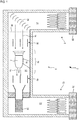
- the figure 1 represents, in a simplified way, a test stand 2 of the engine 4, more particularly a test stand 2 for a turbomachine 4, in particular for an airplane turbojet engine 4.
- the test bench 2 forms an infrastructure, a construction. It comprises a passage 6 with an inlet 8 and an outlet 10.
- the passage 6 may comprise an essentially elongated corridor 12. Its length may be greater than 50 m.
- the length of the corridor 12 allows the flow in a straight line of an air flow 14 or air flow 14 passing through the passage 6. This air flow 14 flows through the test bench 2 because of the breath of the turbojet engine 4.
- the passage 12 may have a passage section greater than or equal to 50 m2.
- the passage section can be measured upstream of the attachment zone 16 intended to receive the turbojet engine 4.
- the attachment zone 16 may be a section of the corridor 12 along its length.
- the passage section may be observable over at least a quarter of the length of the corridor 12, preferably over most of the length.
- the attachment zone 16 is optionally provided with an attachment arm 18, where the turbojet engine 4 is mounted.
- the arm 18 can extend vertically from the ceiling of the corridor 12, in the manner of a column or a pole.
- the arm 18 makes it possible to mount the turbojet engine 4 with an offset, and to center the latter in the middle of the corridor 12. The centering is vertical and horizontal.
- the corridor 12 may be delimited by vertical chimneys (20; 22) at the inlet 8 and at the outlet 10. They allow vertical air intake and exhaust, in elevation with respect to the corridor 12.
- the detailed "U" configuration here is not essential; other configurations, for example without chimneys, are conceivable. Only a room can form the passage.
- the bank 2 is equipped with a series of deflection blades 28. They make it possible to return the air coming down from the inlet chimney 20 in the horizontal direction.
- the deflection blades 28 extend horizontally, and pass through the entire corridor 12. They have curved profiles.
- the bank 2 optionally has a grid 30 for intercepting debris likely to disturb the test and damage the turbojet engine.
- the test bench 2 is here represented in normal test condition, in the usual way. However, to take into account the risk of fire at the turbojet engine 4, the test bench 2 has shutters (38; 40). In particular, a first upstream shutter 38 is placed upstream of the engine 4, while a second shutter 40 is placed downstream. Each shutter (38; 40) has a set of flaps distributed through the passage 6, and which are spaced from each other in the open position.
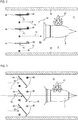
- the figure 2 is a portion of the test bench including the engine 4 and a shutter, for example the upstream shutter 38. The latter is here in the open position. A corridor portion 12 of the passage 6 is shown.
- a fire 42 has just declared on the engine 4, which corresponds to an unusual, abnormal operation of the test bench.
- the shutter 38 comprises several flaps 44.
- the flaps 44 each comprise a pivot connection 50 with a horizontal pivot axis.
- the flaps 44 are parallel to the same plane and are spaced between them to allow the passage of the air flow 14.
- 3 flaps are shown, however any other number is possible, for example ten or fifteen or twenty on the same shutter 38.
- the shutters 44 may show plate shapes, for example rectangular.
- First locking means 46 can hold each shutter in the open position.
- the flaps 44 may be parallel to the ceiling 48 and the floor 48 of the corridor 12.
- the ceiling 48 and the floor 48 form walls defining the corridor 12 and therefore the passage 6. They are joined by vertical walls 48, also called side walls 48, so as to surround the passage 12 and thus the passage 6.
- the first locking means 46 may be arranged on the vertical walls 48.
- the pivots 50 are placed in half upstream of the flaps 44 so as to promote their tilting during the release of the first locking means 46.
- the figure 3 illustrates the test bench portion of the figure 2 after the first locking means 46 have been unlocked. In parallel, the motor 4 is cut. In response to the detection of the fire 42, the first locking means 46 released the flaps 44 leaving the latter free.
- the flaps 44 Due to the imbalance between their upstream halves and their downstream halves relative to the respective pivots 50, the flaps 44 swing. They are inclined with respect to the previous position. Their lower ends are close to the flap 44 from below. This pivoting movement occurs under the effect of gravity, this gravitational force forming a means of return. Thus, the movement of the flaps 44 to the closed position is free of energy source.
- the flaps 44 move autonomously in terms of motive power. This simplifies the design of the flaps 44 and provides a gain in reliability.
- the autorotation of the engine 4 continues to cause the air flow 14. The latter exerts a mechanical force against the shutter 38, and in particular against the flaps 44. This mechanical force opposes the complete closure of the engine. shutter 38, which remains in a partial closed position.
- the dynamic pressure of the air flow 14 can be exploited.
- the flaps 44 remain at a distance from each other since they are pushed by the air flow 14.
- a threshold S the shutter 38 remains partially open.
- This threshold S may depend on the balancing of the flaps 44, and / or their aerodynamic profiles.
- Elastic return means (not shown) can can be added or can replace the offset of the pivots 50. These elastic means increase the threshold value S.
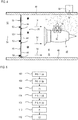
- the figure 4 has the upstream shutter 38 in closed configuration. This figure shows the portion of the detailed test bench in relation to the Figures 1 to 3 . At present, the air flow 14 is less than or equal to the threshold S, so that its mechanical force on the shutter 38 is less than the force exerted by the return means.
- the shutter 38 continues to fall.
- the flaps 44 each comprising a pivot link 50 continue to pivot downwards to come into contact with each other. They can touch each other, and possibly abut against each other, for example at their upper edges and their lower edges.
- Second locking means 52 can hold each flap 44 in the closed position.
- the flaps 44 are vertical and form a partition both waterproof and continuous. They can come into contact with the upper wall 48 and the lower wall 48. They can scrape the vertical walls 48 in a sealed manner. The resulting partition closes the passage 6 in a generally leaktight manner. The circulation of the air flow 14 through the passage 12 is cut off.
- the force of the air flow 14 can also vary depending on the flaps 44.
- the shutters 44 can gain their closed positions one after the other.
- the shutters close to the partitions may close before those at the axis of the engine 4, this axis may correspond to the central axis 54 of the corridor 12.
- the motor attachment zone 16 is rendered inert.
- the test bench may include an inerting system 56 capable of propelling an inert gas 58 in the passage 6. This fights the fire and allows it to be extinguished. What has been described in relation to the upstream shutter can also be applied to the downstream shutter.
- the figure 5 presents a diagram of the process of extinguishing a fire in a test bench.
- the test bench may be identical to that presented in relation to the Figures 1 to 4 .
- the engine may be an aircraft turbojet, for example capable of creating a thrust of at least 120 kN. This thrust results from the entrainment of the air flow through the passage of the test bench. The air flow exerts a mechanical force against each shutter present in the passage. As soon as a fire is detected during step (b) detection 102, the engine is cut. He is no longer supplied with energy; either in fuel. But the inertia of its rotor, coupled with its speed of rotation during the test, continues to rotate its fan so that the air flow continues to be driven through the passage. As a result, the shutters continue to be subjected to a thrust related to the flow of air.
- each shutter pivots to its closed position. This movement is driven by the return means. Gravitation can lower the shutters. They are then essentially mounted free in rotation. In addition or alternatively, permanent magnets and / or springs can equip the shutters to fold the flaps to the closed position. Due to the persistence of the airflow, the closure movement of the shutters is limited. The movement is constrained so that the shutters remain in equilibrium at a distance from their closed position as long as the air flow remains greater than a threshold S.
- the shutter remains partially open for at least 1 second, preferably for at least 5 seconds, more preferably at least 20 seconds, possibly for at least 1 minute.
- step (e) shutter (s) in the closed position 108, the air flow has become less than or equal to the threshold S. Therefore, the mechanical action of the return means is sufficiently high to bring each shutter in position closed.
- the flow pushed by the engine is no longer sufficient to move the shutters from their closed position.
- the shutters can close in offset in time.
- the shutters can optionally be locked in place to hold them closed during the lock step (f).
- this step is optional.
- the simple contact between the flaps may be sufficient to ensure sufficient sealing.
- the presence of magnets at the upper and lower ends of the flaps can block them in the closed position. This magnetic action also increases the threshold S.
- an inert gas is injected therein to suffocate the fire.
- This pressurized inert gas expels the remaining oxygen.
- the oxygen can be sucked up or evacuated by means of a controlled leak through the shutters.
- Other methods of extinction are possible, such as sprinkling.
Landscapes
- Engineering & Computer Science (AREA)
- Chemical & Material Sciences (AREA)
- Combustion & Propulsion (AREA)
- Physics & Mathematics (AREA)
- General Physics & Mathematics (AREA)
- General Engineering & Computer Science (AREA)
- Mechanical Engineering (AREA)
- Health & Medical Sciences (AREA)
- Public Health (AREA)
- Business, Economics & Management (AREA)
- Emergency Management (AREA)
- Fluid Mechanics (AREA)
- Structural Engineering (AREA)
- Architecture (AREA)
- Civil Engineering (AREA)
- Testing Of Engines (AREA)
Description
- L'invention a trait aux essais des turbomachines d'aéronef. Plus précisément, l'invention concerne un banc d'essai adapté pour y étouffer un incendie se déclarant sur le moteur. L'invention propose en outre un procédé d'extinction d'incendie dans un banc d'essai.
- Lors de la conception ou de l'entretien d'une turbomachine, tel un turboréacteur, différents tests sont réalisés afin de valider son bon fonctionnement. Ces tests permettent de contrôler la résistance lors de phases de fonctionnement prolongées, en maintenant des régimes, des efforts prédéterminés. Lors de ces tests, une série de mesures est effectuée pour surveiller des paramètres clés. Ces mesures peuvent à la fois s'effectuer directement sur la turbomachine, ou sur son environnement.
- Afin de conduire de tels tests, la turbomachine est installée dans un banc d'essai spécifique. Celui-ci est adapté pour recréer des conditions de vol tout en restant au sol. Un tel banc d'essai présente un couloir formant une chambre d'essai recevant la turbomachine. Des cheminées verticales délimitent les extrémités du couloir pour former une entrée et une sortie. Les cheminées reçoivent puis rejettent le flux d'air propulsé par la turbomachine. Des dispositifs réduisent les nuisances sonores inhérentes au fonctionnement de la turbomachine, et qui sont propagées par les cheminées.
- Le document de brevet
US 2011/0138772 A1 divulgue un banc d'essai de turboréacteur permettant de récupérer l'énergie cinétique produite par les gaz d'échappement du turboréacteur. Le banc d'essai présente une configuration en « U », c'est-à-dire qui montre une cheminée d'entrée et une cheminée de sortie, les cheminées étant reliées par un couloir horizontal contenant la turbomachine. - Pendant un essai, une conduite d'huile ou de carburant peut rompre. Un incendie moteur risque alors de se déclarer. Un tel événement peut dégrader le banc d'essai, et en particulier ses capteurs. Inévitablement, la turbomachine peut elle-même subir de lourds dégâts. Les conséquences d'un tel incident provoquent de lourds dommages, nécessitant ensuite des réparations qui retardent encore la possibilité de réutiliser la turbomachine. Ce scénario devient paradoxal dans le contexte d'une révision, puisqu'un test est censé autoriser le vol d'une turbomachine au lieu d'ajouter de l'attente. De lourdes pertes financières résultent de ces immobilisations au sol.
- L'invention a pour objectif de résoudre au moins un des problèmes posés par l'art antérieur. Plus précisément, l'invention a pour objectif de réduire l'impact d'un incendie se déclarant dans le banc d'essai. L'invention a également pour autre objectif de fournir un banc d'essai robuste et fiable.
- L'invention a pour objet un banc d'essai pour moteur, notamment pour turboréacteur ou pour turbopropulseur apte à entraîner un flux d'air, le banc d'essai comprenant : une entrée ; une sortie ; un passage en communication avec l'entrée et la sortie, le passage étant destiné à recevoir le moteur lors des essais ; remarquable en ce que le passage comprend au moins un obturateur pivotant au moins entre une position ouverte, et une position fermée afin de couper une circulation d'air dans le passage ; notamment en cas d'incendie ; et en ce qu'il comprend des moyens de rappel autonomes énergiquement, lesdits moyens étant configurés pour ramener ledit obturateur vers sa position fermée. Selon un mode avantageux de l'invention, l'obturateur comprend un volet ou une série de volets configuré(s) de manière à former une cloison continue apte à obturer le passage en position fermée de l'obturateur.
- Selon un mode avantageux de l'invention, l'obturateur comprend au moins une plaque dont la largeur est supérieure à au moins dix fois l'épaisseur, ou au moins vingt fois l'épaisseur.
Selon un mode avantageux de l'invention, dans la position ouverte de l'obturateur, le ou chaque volet est parallèle à l'allongement principal du passage, et/ou dans la position fermée le ou chaque volet est incliné par rapport à l'allongement principal du passage.
Selon un mode avantageux de l'invention, l'axe de pivotement de l'obturateur est horizontal, ou incliné par rapport à la direction verticale, l'obturateur étant équilibré selon son axe de pivotement de manière à être ramené vers la position fermée de manière gravitationnelle, éventuellement l'obturateur comprend un lest.
Selon un mode avantageux de l'invention, les moyens de rappel comprennent des moyens élastiques précontraints de sorte à ramener l'obturateur en position fermée.
Selon un mode avantageux de l'invention, les moyens de rappel comprennent un aimant permanent apte à ramener vers la position fermée et/ou à maintenir en position fermé l'obturateur.
Selon un mode avantageux de l'invention, l'obturateur est destiné à être disposé en aval ou en amont du moteur.
Selon un mode avantageux de l'invention, l'obturateur est un premier obturateur ; le passage comprenant en outre un deuxième obturateur à distance du premier obturateur afin de délimiter un tronçon du passage entre eux ; les deux obturateurs étant aptes à couper la circulation d'air entre l'entrée et la sortie du passage de sorte à pouvoir étouffer un incendie dans le tronçon.
Selon un mode avantageux de l'invention, le banc d'essai comprend un système d'inertage apte à propulser un gaz inerte dans le passage, et/ou des moyens de fixation du moteur placés dans une zone de fixation du moteur, le système d'inertage étant éventuellement disposé dans ladite zone.
Selon un mode avantageux de l'invention, le banc est un banc d'essai pour turboréacteur ou pour turbopropulseur destiné à entraîner un flux d'air traversant le passage, l'obturateur étant apte à être éloigné de la position fermée par le flux d'air lorsque le flux d'air est supérieur à un seuil S, et/ou l'obturateur est configuré de manière à être en position fermée lorsque le flux est inférieur ou égal au seuil S.
Selon un mode avantageux de l'invention, l'obturateur comprend une liaison pivot qui est excentrée par rapport audit obturateur ; préférentiellement en position fermée, l'obturateur présente une moitié supérieure et une moitié inférieure, le pivot étant disposé au niveau de la moitié supérieure.
Selon un mode avantageux de l'invention, en position ouverte, le ou chaque volet est horizontal et/ou à plat.
Selon un mode avantageux de l'invention, en fonctionnement habituel du moteur, l'obturateur est maintenu en position ouverte et/ou le flux d'air entraîné par le moteur exerce sur l'obturateur une pression dynamique supérieure à un seuil S.
Selon un mode avantageux de l'invention, le passage comprend un couloir destiné à recevoir le moteur et/ou des cheminées verticales, l'obturateur étant préférentiellement situé dans le couloir.
Selon un mode avantageux de l'invention, le couloir comprend des moyens de fixation du moteur placé dans une zone de fixation du moteur ; éventuellement munie de capteurs.
Selon un mode avantageux de l'invention, l'obturateur est un premier obturateur situé en amont du moteur, le passage comprenant en outre un deuxième obturateur situé en aval du moteur, les deux obturateurs étant aptes à couper la circulation d'air entre l'entrée et la sortie du passage de sorte à pouvoir étouffer un incendie se déclarant dans le passage au niveau du moteur.
Selon un mode avantageux de l'invention, l'obturateur en amont pivote en position fermée lorsqu'il est exposé à une pression dynamique P1 inférieure à un seuil S1, et en ce que l'obturateur en aval pivote en position fermée lorsqu'il est exposé à une pression dynamique inférieure à un seuil S2, les seuils S1 et S2 étant différents.
Selon un mode avantageux de l'invention, l'obturateur aval se ferme après l'obturateur amont. - Selon un mode avantageux de l'invention, chaque obturateur se ferme progressivement, notamment chaque volet atteint sa position fermée progressivement, et/ou les volets d'un même obturateur atteignent leurs positions fermées les uns après les autres.
Selon un mode avantageux de l'invention, le passage comprend un sens de circulation d'air de l'entrée vers la sortie, éventuellement le sens principal est selon l'axe central du passage.
Selon un mode avantageux de l'invention, le passage comprend des parois en béton armé de treillis métallique, et éventuellement des fondations, par exemple au niveau d'au moins un ou de chaque obturateur.
Selon un mode avantageux de l'invention, le passage et/ou le couloir mesure plus de 10 m de long, préférentiellement plus de 20 m de long, plus préférentiellement plus de 70 m de long. La longueur du couloir peut être mesurée en ligne droite.
Selon un mode avantageux de l'invention, le passage présente une section de passage d'au moins 4m2, ou 25 m2, ou 50 m2, ou 100 m2.
Selon un mode avantageux de l'invention, le banc d'essai comprend un bras de fixation, éventuellement une potence ou une suspente, adaptée à la fixation du moteur.
Selon un mode avantageux de l'invention, le moteur est apte à exercer une poussée supérieure ou égale à 20 kN, ou 80 kN, ou 200 kN, 500 kN. Le bras de fixation étant conçu pour reprendre les efforts correspondants.
Selon un mode avantageux de l'invention, le ou au moins un ou chaque obturateur est monté libre en rotation par rapport au banc d'essai ; et/ou chaque volet est monté libre en rotation par rapport aux autres volets.
Selon un mode avantageux de l'invention, la ou chaque cloison est étanche ou généralement étanche.
Selon un mode avantageux de l'invention, la zone de fixation du moteur comprend des capteurs de mesure, notamment des capteurs de température, ou de pression, ou de mesure de débit. - Selon un mode avantageux de l'invention, dans la position fermée le, ou au moins un, ou chaque volet est généralement perpendiculaire à l'allongement principal du passage.
Selon un mode avantageux de l'invention, le banc d'essai comprend des moyens de maintien de l'obturateur en position ouverte et/ou des moyens de maintien de l'obturateur dans la position fermée - L'invention a également pour objet un banc d'essai pour moteur, notamment pour turboréacteur ou pour turbopropulseur apte à entraîner un flux d'air, le banc d'essai comprenant : une entrée ; une sortie ; un passage en communication avec l'entrée et la sortie, le passage étant destiné à recevoir le moteur lors des essais, remarquable en ce que le passage comprend un obturateur pivotant entre une position ouverte, et une position fermée afin de couper une circulation d'air dans le passage ; notamment en cas d'incendie ; l'obturateur apte à être ramené en position fermée par action de la force gravitationnelle ; et/ou l'obturateur est apte à être éloigné de la position fermée par un flux d'air entraîné par le moteur au travers du passage.
- L'invention a également pour objet un procédé d'extinction d'incendie dans un banc d'essai pour moteur, notamment pour turboréacteur ou turbopropulseur, le procédé comprenant les étapes suivantes : (a) réalisation d'un test moteur sur le banc d'essai ; (b) détection d'un incendie ; remarquable en ce que le banc comprend un obturateur pivotant entre une position ouverte et une position fermée ; le procédé comprend en outre une étape (d) pivotement de l'obturateur vers la position fermée de manière autonome énergiquement, éventuellement le banc d'essai est conforme à l'invention.
Selon un mode avantageux de l'invention, le moteur est un turboréacteur ou un turbopropulseur d'avion, et en ce que suite à l'étape (b) détection, le moteur est coupé ; et lors de l'étape (d) pivotement, le moteur continue de tourner de sorte à entrainer un flux d'air qui maintient l'obturateur partiellement ouvert.
Selon un mode avantageux de l'invention, lors de l'étape (d) pivotement, l'obturateur reste partiellement ouvert pendant au moins 1 seconde, préférentiellement pendant au moins 5 secondes, plus préférentiellement au moins 20 secondes, éventuellement pendant au moins 1 minute.
De manière générale, les modes avantageux de chaque objet de l'invention sont également applicables aux autres objets de l'invention. Dans la mesure du possible, chaque objet et chaque mode avantageux sont combinables. - La présence d'un ou plusieurs volets pivotant permet d'améliorer la compacité de l'obturateur et de limiter son impact sur le flux circulant dans le banc d'essai.
- En position ouverte ; chaque obturateur est partiellement, préférentiellement totalement inscrit dans le passage, notamment dans le couloir, ce qui permet de l'obturer encore plus vite.
- La présence de moyens de rappel entrainant la fermeture de l'obturateur en cas de fonctionnement inhabituel du moteur permet une gestion des incendies rapide, autonome et économe en énergie. Ceci améliore d'ailleurs la fiabilité d'obturation.
- Deux obturateurs permettent de confiner une zone réduite, de sorte à favoriser l'asphyxie d'un incendie qui s'y déclencherait. Ils sont placés à proximité du turboréacteur, ce qui permet de supprimer l'oxygène restant dans l'enceinte qu'ils forment. La présence d'un système d'inertage activé par la fermeture des obturateurs accélère la gestion de l'incendie.
- En raison de l'inertie du rotor d'un turboréacteur d'avion, le flux d'air continue d'être entraîné malgré la coupure de l'alimentation en énergie. Puisque les volets restent partiellement ouverts lorsque le flux continue de circuler au-delà d'un certain seuil, ils peuvent être dimensionnés de manière plus légère. En effet, ils n'ont pas besoin de rester fermés en résistant à un flux élevé de la turbomachine. Ainsi, l'obturateur peut être aminci, si bien qu'il perturbe à minima le test.
-
- La
figure 1 représente un banc d'essai selon l'invention recevant un moteur en phase de test. - La
figure 2 est un schéma d'un obturateur amont en position ouverte selon l'invention, un incendie venant de se déclarer. - La
figure 3 est un schéma de l'obturateur amont en cours de fermeture selon l'invention, en réponse à un départ d'incendie. - La
figure 4 est un schéma d'un obturateur amont en position fermée selon l'invention. - La
figure 5 illustre un diagramme du procédé d'extinction d'incendie dans un banc d'essai selon l'invention. - La
figure 1 représente de manière simplifiée un banc d'essai 2 de moteur 4, plus particulièrement un banc d'essai 2 pour turbomachine 4, notamment pour turboréacteur 4 d'avion.
Le banc d'essai 2 forme une infrastructure, une construction. Il comprend un passage 6 avec une entrée 8 et une sortie 10. Le passage 6 peut comprendre un couloir 12 essentiellement allongé. Sa longueur peut être supérieure à 50 m. La longueur du couloir 12 permet la circulation en ligne droite d'un flux d'air 14 ou circulation d'air 14 traversant la passage 6. Ce flux d'air 14 circule au travers du banc d'essai 2 en raison du souffle du turboréacteur 4. Afin de limiter la résistance à l'écoulement, en particulier l'entrée d'un flux d'air 14 dans le turboréacteur 4, le couloir 12 peut présenter une section de passage supérieure ou égale à 50 m2. La section de passage, ou section libre, peut être mesurée en amont de la zone de fixation 16 destinée à recevoir le turboréacteur 4. La zone de fixation 16 peut être un tronçon du couloir 12 selon sa longueur. La section de passage peut être observable sur au moins un quart de la longueur du couloir 12, préférentiellement sur la majorité de la longueur.
La zone de fixation 16, est éventuellement munie d'un bras de fixation 18, où le turboréacteur 4 est monté. Le bras 18 peut s'étendre verticalement depuis le plafond du couloir 12, à la manière d'une colonne ou d'un poteau. Le bras 18 permet de monter le turboréacteur 4 avec un déport, et de centrer ce dernier au milieu du couloir 12. Le centrage est vertical et horizontal. - Le couloir 12 peut être délimité par des cheminées verticales (20 ; 22) en entrée 8 et en sortie 10. Elles permettent une admission d'air et un échappement verticaux, en élévation par rapport au couloir 12. La configuration en « U » détaillée ici n'est pas indispensable ; d'autres configurations, par exemple sans cheminées, sont envisageables. Seule une chambre peut former le passage.
A la jonction entre la cheminée amont 20 et le couloir 12, le banc 2 est équipé d'une série de lames de déviation 28. Elles permettent de renvoyer l'air descendant de la cheminée d'entrée 20 selon la direction horizontale. Les lames de déviation 28 s'étendent horizontalement, et traversent tout le couloir 12. Elles présentent des profils courbes. En entrée du couloir 12, le banc 2 présente optionnellement une grille 30 permettant d'intercepter des débris susceptibles de perturber l'essai et d'endommager le turboréacteur.
Le banc d'essai 2 est ici représenté en condition normale de test, de manière habituelle. Toutefois, pour prendre en compte le risque d'incendie au niveau du turboréacteur 4, le banc d'essai 2 est doté d'obturateurs (38 ; 40). En particulier, un premier obturateur amont 38 est placé en amont du moteur 4, tandis qu'un deuxième obturateur 40 est placé en aval. Chaque obturateur (38 ; 40) présente un jeu de volets répartis au travers du passage 6, et qui sont distants les uns des autres en position ouverte.
Lafigure 2 est une portion du banc d'essai incluant le moteur 4 et un obturateur, par exemple l'obturateur amont 38. Ce dernier est ici en position ouverte. Une portion de couloir 12 du passage 6 y est représentée. Un incendie 42 vient de se déclarer sur le moteur 4, ce qui correspond à un fonctionnement inhabituel, anormal du banc d'essai.
L'obturateur 38 comprend plusieurs volets 44. Les volets 44 comprennent chacun une liaison pivot 50 avec un axe de pivotement horizontal. Les volets 44 sont parallèles à un même plan et sont espacés entre eux afin de permettre le passage du flux d'air 14. Ici, 3 volets sont représentés, néanmoins tout autre nombre est envisageable, par exemple dix ou quinze ou vingt sur un même obturateur 38. Les volets 44 peuvent montrer des formes de plaques, par exemples rectangulaires. - Des premiers moyens de verrouillage 46 peuvent maintenir chaque obturateur en position ouverte. Les volets 44 peuvent être parallèles au plafond 48 et au sol 48 du couloir 12. Le plafond 48 et le sol 48 forment des parois délimitant le couloir 12 et donc le passage 6. Ils sont joints par des parois verticales 48, également appelées parois latérales 48, de manière à entourer le couloir 12 et donc le passage 6. Les premiers moyens de verrouillage 46 peuvent être disposés sur les parois verticales 48. Les pivots 50 sont placés en moitié amont des volets 44 de sorte à favoriser leur basculement lors de la libération des premiers moyens de verrouillage 46.
Lafigure 3 illustre la portion de banc d'essai de lafigure 2 après que les premiers moyens de verrouillage 46 aient été déverrouillés. En parallèle, le moteur 4 est coupé.
En réponse à la détection de l'incendie 42, les premiers moyens de verrouillage 46 ont libéré les volets 44 laissant libres ces derniers. En raison du déséquilibre entre leurs moitiés amont et leurs moitiés aval par rapport aux pivots 50 respectifs, les volets 44 basculent. Ils sont inclinés par rapport à la position précédente. Leurs extrémités inférieures se rapprochent du volet 44 du dessous. Ce mouvement de pivotement se produit sous l'effet de la gravité, cette force gravitationnelle formant un moyen de rappel. Ainsi, le déplacement des volets 44 vers la position fermée est libre de source d'énergie. Les volets 44 se déplacent de manière autonome en terme d'énergie motrice. Ceci simplifie la conception des volets 44 et offre un gain de fiabilité.
Cependant, l'autorotation du moteur 4 continue d'entrainer le flux d'air 14. Ce dernier exerce un effort mécanique contre l'obturateur 38, et notamment contre les volets 44. Cet effort mécanique s'oppose à la fermeture complète de l'obturateur 38, qui reste dans une position de fermeture partielle. La pression dynamique du flux d'air 14 peut être exploitée. Les volets 44 restent à distance les uns des autres puisqu'ils sont poussés par le flux d'air 14. Tant que le flux d'air 14 reste supérieur à un seuil S, l'obturateur 38 reste partiellement ouvert. Ce seuil S peut dépendre de l'équilibrage des volets 44, et/ou de leurs profils aérodynamiques. Des moyens élastiques de rappel (non représentés) peuvent être ajoutés ou peuvent remplacer le désaxage des pivots 50. Ces moyens élastiques augmentent la valeur seuil S.
Lafigure 4 présente l'obturateur amont 38 en configuration fermée. Cette figure présente la portion de banc d'essai détaillée en relation avec lesfigures 1 à 3 .
A présent, le flux d'air 14 est inférieur ou égal au seuil S, si bien que son effort mécanique sur l'obturateur 38 est inférieur à l'effort qu'exercent les moyens de rappel. L'obturateur 38 continue de baisser. Les volets 44 comprenant chacun une liaison pivot 50 continuent de pivoter vers le bas jusqu'à venir en contact les uns des autres. Ils peuvent se toucher, et éventuellement buter les uns contre les autres, par exemple au niveau de leurs bords supérieurs et de leurs bords inférieurs. Des deuxièmes moyens de verrouillage 52 peuvent maintenir chaque volet 44 en position fermée.
Les volets 44 sont verticaux et forment une cloison à la fois étanche et continue. Ils peuvent venir en contact de la paroi supérieure 48 et de la paroi inférieure 48. Ils peuvent racler de manière étanche les parois verticales 48. La cloison résultante obture le passage 6 de manière généralement étanche. La circulation du flux d'air 14 au travers du couloir 12 est coupée.
Puisque le flux d'air 14 peut montrer une distribution variable en fonction de la proximité des parois 48 et de l'axe central 54 du couloir 12, l'effort du flux d'air 14 peut également varier selon les volets 44. Ainsi, les volets 44 peuvent gagner leurs positions fermées les uns après les autres. Par exemple, les volets proches des cloisons peuvent se fermer avant ceux au niveau de l'axe du moteur 4, cet axe pouvant correspondre à l'axe central 54 du couloir 12.
Une fois confinée, la zone de fixation 16 moteur est rendue inerte. Le banc d'essai peut comporter un système d'inertage 56 apte à propulser un gaz inerte 58 dans le passage 6. Ceci combat l'incendie et permet de l'éteindre.
Ce qui a été décrit en relation avec l'obturateur amont peut également s'appliquer à l'obturateur aval.
Lafigure 5 présente un diagramme du procédé d'extinction d'un incendie dans un banc d'essai. Le banc d'essai peut être identique à celui présenté en relation avec lesfigures 1 à 4 . - Le procédé peut prendre les étapes suivantes, éventuellement effectuées dans l'ordre qui suit :
- (a)- réalisation d'un test 100 moteur dans le passage du banc d'essai, chaque obturateur étant alors en position ouverte ;
- (b)- détection 102 d'un incendie sur le moteur ;
- (c)- déverrouillage 104 des obturateurs afin d'autoriser leur pivotement ;
- (d)- pivotement 106 de chaque obturateur vers sa position fermée respective à l'aide des moyens de rappel ;
- (e)- obturateurs en position fermée 108;
- (f)- verrouillage 110 des obturateurs en position fermée ;
- (g)- inertage 112 de la zone au niveau du moteur afin d'y éteindre l'incendie.
- Lors de l'étape (a) réalisation d'un test 100, le moteur peut être un turboréacteur d'avion, par exemple apte à créer une poussée d'au moins 120 kN. Cette poussée résulte de l'entrainement du flux d'air au travers du passage du banc d'essai. Le flux d'air exerce un effort mécanique contre chaque obturateur présent dans le passage.
Dès qu'un incendie est détecté lors de l'étape (b) détection 102, le moteur est coupé. Il n'est plus alimenté en énergie ; soit en carburant. Mais l'inertie de son rotor, conjuguée à sa vitesse de rotation lors du test, continue de faire tourner sa soufflante si bien que le flux d'air continue d'être entraîné au travers du passage. En conséquence de quoi, les obturateurs continuent d'être soumis à une poussée liée au flux d'air.
Lors de l'étape (d) pivotement 106, chaque obturateur pivote vers sa position fermée. Ce mouvement est entraîné par les moyens de rappel. La gravitation peut permettre de descendre les obturateurs. Ils sont alors essentiellement montés libre en rotation. En complément ou en alternative, des aimants permanents et/ou des ressorts peuvent équiper les obturateurs pour rabattre les volets vers la position fermée.
En raison de la persistance du flux d'air, le mouvement de fermeture des obturateurs est limité. Le mouvement est contraint si bien que les obturateurs restent en équilibre à distance de leur position fermée tant que le flux d'air reste supérieur à un seuil S.
Lors de l'étape (d) pivotement, l'obturateur reste partiellement ouvert pendant au moins 1 seconde, préférentiellement pendant au moins 5 secondes, plus préférentiellement au moins 20 secondes, éventuellement pendant au moins 1 minute.
A l'étape (e) obturateur(s) en position fermée 108, le flux d'air est devenu inférieur ou égal au seuil S. Dès lors, l'action mécanique des moyens de rappel est suffisamment élevée pour amener chaque obturateur en position fermée. Le flux poussé par le moteur n'est plus suffisant pour écarter les obturateurs de leur position fermée. Les obturateurs peuvent se fermer en décalé dans le temps.
Ensuite, les obturateurs peuvent optionnellement être verrouillés en place afin de les maintenir en position fermée lors de l'étape verrouillage (f). Toutefois cette étape est optionnelle. Le simple contact entre les volets peut suffire à assurer une étanchéité suffisante. Par ailleurs, la présence d'aimants aux extrémités supérieures et inférieures des volets peut les bloquer en position fermée. Cette action magnétique permet également d'augmenter le seuil S. Une fois que l'espace recevant le moteur est confiné, c'est-à-dire fermé de manière étanche, il peut être rendu inerte. L'air ne s'y renouvelle plus. Selon une autre approche, un gaz inerte y est injecté afin d'asphyxier l'incendie. Ce gaz inerte pressurisé chasse l'oxygène restant. L'oxygène peut être aspiré ou s'évacuer moyennant une fuite contrôlée au travers des obturateurs. D'autres méthodes d'extinction sont possibles, comme une aspersion.
Claims (15)
- Banc d'essai (2) pour moteur (4), notamment pour turboréacteur ou pour turbopropulseur apte à entraîner un flux d'air (14), le banc d'essai (2) comprenant :- une entrée (8);- une sortie (10);- un passage (6) en communication avec l'entrée (8) et la sortie (10), le passage (6) étant destiné à recevoir le moteur (4) lors des essais,caractérisé en ce que le passage (6) comprend au moins un obturateur pivotant (38 ; 40) au moins entre une position ouverte, et une position fermée afin de couper une circulation d'air dans le passage (6); notamment en cas d'incendie (42) ;
et en ce qu'il comprend des moyens de rappel autonomes énergiquement, lesdits moyens étant configurés pour ramener ledit obturateur (38 ; 40) vers sa position fermée. - Banc (2) selon la revendication 1, caractérisé en ce que l'obturateur (38 ; 40) comprend un volet (44) ou une série de volets (44) configuré(s) de manière à former une cloison continue apte à obturer le passage (6) en position fermée de l'obturateur (38 ; 40).
- Banc (2) selon l'une des revendications 1 à 2, caractérisé en ce que l'obturateur (38 ; 40) comprend au moins une plaque (44) dont la largeur est supérieure à au moins dix fois l'épaisseur, ou au moins vingt fois l'épaisseur.
- Banc (2) selon l'une des revendications 2 à 3, caractérisé en ce que dans la position ouverte de l'obturateur (38 ; 40), le ou chaque volet (44) est parallèle à l'allongement principal du passage (6), et/ou dans la position fermée le ou chaque volet (44) est incliné par rapport à l'allongement principal du passage (6).
- Banc (2) selon l'une des revendications 1 à 4, caractérisé en que l'axe de pivotement de l'obturateur (38 ; 40) est horizontal, ou incliné par rapport à la direction verticale, l'obturateur (38 ; 40) étant équilibré selon son axe de pivotement de manière à être ramené vers la position fermée de manière gravitationnelle, éventuellement l'obturateur (38 ; 40) comprend un lest.
- Banc (2) selon l'une des revendications 1 à 5, caractérisé en ce que les moyens de rappel comprennent des moyens élastiques précontraints de sorte à ramener l'obturateur (38 ; 40) en position fermée.
- Banc (2) selon l'une des revendications 1 à 6, caractérisé en ce que les moyens de rappel comprennent un aimant permanent apte à ramener vers la position fermée et/ou à maintenir en position fermée l'obturateur (38 ; 40).
- Banc (2) selon l'une des revendications 1 à 7, caractérisé en que l'obturateur est destiné à être disposé en aval ou en amont du moteur (4).
- Banc (2) selon l'une des revendications 1 à 8, caractérisé en que l'obturateur est un premier obturateur (38); le passage (6) comprenant en outre un deuxième obturateur (40) à distance du premier obturateur (38) afin de délimiter un tronçon (16) du passage (6) entre eux ; les deux obturateurs (38 ; 40) étant aptes à couper la circulation d'air entre l'entrée (8) et la sortie (10) du passage (6) de sorte à pouvoir étouffer un incendie (42) dans le tronçon (16).
- Banc (2) selon l'une des revendications 1 à 9, caractérisé en ce qu'il comprend un système d'inertage (56) apte à propulser un gaz inerte (58) dans le passage (6), et/ou des moyens de fixation (18) du moteur (4) placés dans une zone de fixation (16) du moteur (4), le système d'inertage (56) étant éventuellement disposé dans ladite zone (16).
- Banc (2) selon l'une des revendications 1 à 10, caractérisé en ce qu'il est un banc d'essai (2) pour turboréacteur ou pour turbopropulseur destiné à entraîner un flux d'air (14) traversant le passage (6), l'obturateur (38 ; 40) étant apte à être éloigné de la position fermée par le flux d'air (14) lorsque le flux d'air (14) est supérieur à un seuil S, et/ou l'obturateur (38 ; 40) est configuré de manière à être en position fermée lorsque le flux (14) est inférieur ou égal au seuil S.
- Banc (2) selon l'une des revendications 1 à 11, caractérisé en ce que l'obturateur (38 ; 40) comprend une liaison pivot (50) qui est excentrée par rapport audit obturateur (38 ; 40); préférentiellement en position fermée, l'obturateur (38 ; 40) présente une moitié supérieure et une moitié inférieure, le pivot (50) étant disposé au niveau de la moitié supérieure.
- Procédé d'extinction d'incendie dans un banc d'essai (2) pour moteur (4), notamment pour turboréacteur ou turbopropulseur, le procédé comprenant les étapes suivantes :(a) réalisation (100) d'un test moteur (4) sur le banc d'essai (2) ;(b) détection (102) d'un incendie ;caractérisé en ce que le banc (2) comprend un obturateur (38 ; 40) pivotant entre une position ouverte et une position fermée ;
le procédé comprend en outre une étape(d) pivotement (106) de l'obturateur (38; 40) vers la position fermée de manière autonome énergiquement, éventuellement le banc d'essai (2) est selon l'une quelconque des revendications 1 à 12. - Procédé selon la revendication 13, caractérisé en ce que le moteur (4) est un turboréacteur ou un turbopropulseur d'avion, et en ce que suite à l'étape (b) détection (102), le moteur (4) est coupé ; et lors de l'étape (d) pivotement (106), le moteur (4) continue de tourner de sorte à entrainer un flux d'air (14) qui maintient l'obturateur (38 ; 40) partiellement ouvert.
- Procédé selon l'une des revendications 13 à 14, caractérisé en ce que lors de l'étape (d) pivotement, l'obturateur (38 ; 40) reste partiellement ouvert pendant au moins 1 seconde, préférentiellement pendant au moins 5 secondes, plus préférentiellement au moins 20 secondes, éventuellement pendant au moins 1 minute.
Applications Claiming Priority (1)
| Application Number | Priority Date | Filing Date | Title |
|---|---|---|---|
| BE2016/5072A BE1023813B1 (fr) | 2016-01-28 | 2016-01-28 | Banc d'essai de turbomachine d'aeronef |
Publications (2)
| Publication Number | Publication Date |
|---|---|
| EP3199206A1 EP3199206A1 (fr) | 2017-08-02 |
| EP3199206B1 true EP3199206B1 (fr) | 2018-12-12 |
Family
ID=55484772
Family Applications (1)
| Application Number | Title | Priority Date | Filing Date |
|---|---|---|---|
| EP17150637.1A Active EP3199206B1 (fr) | 2016-01-28 | 2017-01-09 | Banc d'essai de turbomachine d'aeronef |
Country Status (5)
| Country | Link |
|---|---|
| US (1) | US10226651B2 (fr) |
| EP (1) | EP3199206B1 (fr) |
| CN (1) | CN107013331B (fr) |
| BE (1) | BE1023813B1 (fr) |
| CA (1) | CA2956041C (fr) |
Families Citing this family (18)
| Publication number | Priority date | Publication date | Assignee | Title |
|---|---|---|---|---|
| BE1022921B1 (fr) * | 2015-04-01 | 2016-10-19 | Techspace Aero S.A. | Banc d'essais de turboreacteur d'aeronef avec obturateurs |
| CN108036917B (zh) * | 2017-12-15 | 2019-09-06 | 中国航空工业集团公司金城南京机电液压工程研究中心 | 一种冲压空气涡轮风洞试验测试方法 |
| CN110082139B (zh) * | 2019-04-30 | 2020-06-26 | 中国科学技术大学 | 一种飞机发动机舱哈龙替代灭火系统最低性能试验舱 |
| GB2584712A (en) | 2019-06-13 | 2020-12-16 | Rolls Royce Plc | A forced air convection apparatus and method for cooling a turbomachine |
| BE1027431B1 (fr) * | 2019-07-16 | 2021-02-15 | Safran Aero Boosters Sa | Banc d'essai de turbomachines dépollué |
| CN111323199A (zh) * | 2020-03-31 | 2020-06-23 | 杭州佐格通信设备有限公司 | 风洞的碎片拦截机构以及风洞 |
| CN111649952A (zh) * | 2020-05-11 | 2020-09-11 | 中航长沙设计研究院有限公司 | 涡轴发动机试车引射筒紧急封闭装置 |
| US11592362B2 (en) * | 2020-09-24 | 2023-02-28 | General Electric Company | System and method for full-scale sampling to conduct material tests on a steam turbine rotor |
| US12103690B2 (en) * | 2020-11-05 | 2024-10-01 | United States Of America As Represented By The Secretary Of The Air Force | Ice detection and precautionary system shut-down event reduction systems and related methods |
| FR3120942B1 (fr) | 2021-03-18 | 2023-07-14 | Safran Aircraft Engines | Banc d’essai de turbomachine comportant un dispositif d’admission d’un polluant |
| CN114326578B (zh) * | 2022-03-10 | 2022-07-12 | 东方电气风电股份有限公司 | 变桨加载柜及控制系统 |
| CN114705472B (zh) * | 2022-06-07 | 2022-09-06 | 四川省鼓风机制造有限责任公司 | 一种通风机风力控制测试工装平台及使用方法 |
| CN115628913B (zh) * | 2022-09-14 | 2025-06-27 | 中国航发湖南动力机械研究所 | 空气涡轮起动机真空试验舱 |
| CN116163841A (zh) * | 2022-12-01 | 2023-05-26 | 中国船舶重工集团公司第七0三研究所 | 一种应用在海洋石油平台上的燃气轮机发电机组火气系统 |
| WO2024207062A1 (fr) * | 2023-04-03 | 2024-10-10 | Agnitek Pty Ltd | Boîtier de clapet de canalisation |
| FR3149379B1 (fr) | 2023-06-02 | 2025-10-17 | Safran Aircraft Engines | Filtration de polluant dans un banc d’essai de turbomachine |
| CN116549883A (zh) * | 2023-06-26 | 2023-08-08 | 中国空气动力研究与发展中心超高速空气动力研究所 | 一种大型高超声速高温风洞氮气消防系统及其使用方法 |
| US12247897B1 (en) * | 2023-08-25 | 2025-03-11 | Pratt & Whitney Canada Corp. | Method and apparatus for automated gas turbine engine testing |
Family Cites Families (20)
| Publication number | Priority date | Publication date | Assignee | Title |
|---|---|---|---|---|
| DE2342531A1 (de) * | 1973-08-23 | 1975-02-27 | Hans Guenter Schmidt | Absperr- und drosseleinrichtung fuer lueftungs- und klimasysteme |
| US4432272A (en) * | 1982-11-29 | 1984-02-21 | Ruskin Manufacturing Company | Motor operated fire damper |
| US5092525A (en) * | 1984-11-02 | 1992-03-03 | United Technologies Corporation | Exhaust nozzle with reverser exhaust door mechanism |
| FR2683321B1 (fr) * | 1991-11-06 | 1994-02-11 | Boet Sa Andre | Installation d'essais au sol pour les reacteurs d'un aeronef gros-porteur. |
| US5293775A (en) * | 1992-11-02 | 1994-03-15 | United Technologies Corporation | Gas turbine engine test cell |
| US5396793A (en) * | 1993-09-17 | 1995-03-14 | United Technologies Corporation | Altitude gas turbine engine test cell |
| US5575607A (en) * | 1994-11-02 | 1996-11-19 | United Technologies Corporation | Jet engine transport vehicle lift system and a build cell |
| US5837890A (en) * | 1994-12-12 | 1998-11-17 | Aero Systems Engineering, Inc. | Jet engine test cell structure |
| US5762885A (en) * | 1997-02-19 | 1998-06-09 | Goal Line Environmental Technologies Llc | Apparatus for removing contaminants from gaseous stream. |
| US6237395B1 (en) * | 1999-11-08 | 2001-05-29 | The United States Of America As Represented By The Secretary Of The Navy | Annular after reactor for use with a jet engine test cell |
| US6497137B2 (en) * | 1999-11-08 | 2002-12-24 | The United States Of America As Represented By The Secretary Of The Navy | Annular after reactor with sound attenuator for use in a jet engine test cell and test stand |
| US6742339B2 (en) * | 2002-09-06 | 2004-06-01 | General Electric Company | Methods and apparatus for exhausting gases from gas turbine engines |
| US7174797B2 (en) * | 2002-10-15 | 2007-02-13 | Florida Turbine Technologies, Inc. | High temperature and pressure testing facility |
| JP3580810B1 (ja) * | 2004-05-27 | 2004-10-27 | 川崎重工業株式会社 | 超低周波音用吸音装置 |
| US7574904B1 (en) * | 2005-11-01 | 2009-08-18 | Florida Turbine Technologies, Inc. | Advanced hot section materials and coatings test rig |
| GB2438431B (en) * | 2006-05-25 | 2008-08-20 | Rolls Royce Plc | Thrust correction |
| US20110048847A1 (en) * | 2009-09-02 | 2011-03-03 | United States Of America As Represented By The Secretary Of The Navy | Noise attenuation device for reducing noise attenuation in a jet engine test cell |
| EP2336507B1 (fr) * | 2009-12-16 | 2014-07-30 | MDS Aero support corporation | Désaccordeur de turbine pour récupérer l'énergie cinétique de gaz d'échappement de moteurs à turbine à gaz |
| BE1022921B1 (fr) * | 2015-04-01 | 2016-10-19 | Techspace Aero S.A. | Banc d'essais de turboreacteur d'aeronef avec obturateurs |
| BE1024192B1 (fr) * | 2016-05-09 | 2017-12-12 | Safran Aero Boosters S.A. | Procede et banc d'essai de turbomachine a realite augmentee |
-
2016
- 2016-01-28 BE BE2016/5072A patent/BE1023813B1/fr not_active IP Right Cessation
-
2017
- 2017-01-09 EP EP17150637.1A patent/EP3199206B1/fr active Active
- 2017-01-23 CN CN201710058134.2A patent/CN107013331B/zh active Active
- 2017-01-25 CA CA2956041A patent/CA2956041C/fr active Active
- 2017-01-26 US US15/415,939 patent/US10226651B2/en active Active
Non-Patent Citations (1)
| Title |
|---|
| None * |
Also Published As
| Publication number | Publication date |
|---|---|
| CN107013331A (zh) | 2017-08-04 |
| BE1023813B1 (fr) | 2017-07-31 |
| BE1023813A1 (fr) | 2017-07-28 |
| US10226651B2 (en) | 2019-03-12 |
| CN107013331B (zh) | 2021-04-13 |
| CA2956041C (fr) | 2023-01-03 |
| CA2956041A1 (fr) | 2017-07-28 |
| US20170216637A1 (en) | 2017-08-03 |
| EP3199206A1 (fr) | 2017-08-02 |
Similar Documents
| Publication | Publication Date | Title |
|---|---|---|
| EP3199206B1 (fr) | Banc d'essai de turbomachine d'aeronef | |
| EP3085419B1 (fr) | Banc d'essais de turboreacteur d'aeronef avec obturateurs | |
| CA2689111C (fr) | Ensemble moteur pour aeronef a nacelle coulissante | |
| EP1914040B1 (fr) | Procédés et installations de grenaillage | |
| FR2623250A1 (fr) | Dispositif de ventilation pour la nacelle d'un moteur a turbine a gaz notamment pour un aeronef | |
| WO2008000924A1 (fr) | Nacelle structurante | |
| CA2715738A1 (fr) | Ensemble moteur pour aeronef comprenant des attaches moteur deportees vers le bas sur le carter de soufflante | |
| FR3120942A1 (fr) | Banc d’essai de turbomachine comportant un dispositif d’admission d’un polluant | |
| FR2964942A1 (fr) | Enceinte de protection des pignons de commande du pas d'une helice d'open-rotor | |
| CA2942461A1 (fr) | Dispositif d'inversion de poussee a portes pour nacelle de turboreacteur d'aeronef | |
| EP3022405B1 (fr) | Dispositif de dépose pour aubes et procédé de dépose correspondant | |
| FR3043650A1 (fr) | Aube de stator de turbomachine, carter de soufflante comprenant une telle aube, systeme d'inversion de poussee d'une turbomachine equipee d'une telle aube et turbomachine equipee de ladite aube, dudit carter ou dudit systeme | |
| EP3755627B1 (fr) | Ensemble de motorisation pour aeronef comportant des points de levage, et chariots pour supporter un tel ensemble | |
| FR3111160A1 (fr) | Moteur d’aéronef | |
| EP4286019B1 (fr) | Aéronef comportant une canalisation de transport de dihydrogène, un canal d'enfouissement de ladite canalisation de transport et un système d'aération dudit canal d'enfouissement | |
| FR3010431A1 (fr) | Plateforme d'acces a une machine hydraulique et methodes d'installation et de demontage d'une telle plateforme dans un tube d'aspiration | |
| BE1023509A1 (fr) | Banc de test de turbomachine sur bateau | |
| EP4345009B1 (fr) | Ensemble propulsif pour aéronef | |
| FR3000477A1 (fr) | Prevention du debordement de liquide en dehors d'une installation a l'air libre de stockage de liquide. | |
| FR2930817A1 (fr) | Systeme d'obturation d'un conduit d'evacuation des gaz d'un lanceur de missiles | |
| EP2428675B1 (fr) | Installation hydroélectrique et ensemble turbine amovible pour celle-ci | |
| EP3106655A1 (fr) | Turbine hydraulique à flux traversant | |
| FR3135706A1 (fr) | Groupe propulsif, aeronef et mise en œuvre en plein vol | |
| FR3151299A1 (fr) | Ensemble propulsif pour aéronef | |
| FR3027969A1 (fr) | Dispositif de production d'electricite a l'aide d'une turbine a axe vertical, dont les moyens de prise au vent ou l'eau sont constitues de pales pivotantes |
Legal Events
| Date | Code | Title | Description |
|---|---|---|---|
| PUAI | Public reference made under article 153(3) epc to a published international application that has entered the european phase |
Free format text: ORIGINAL CODE: 0009012 |
|
| STAA | Information on the status of an ep patent application or granted ep patent |
Free format text: STATUS: THE APPLICATION HAS BEEN PUBLISHED |
|
| AK | Designated contracting states |
Kind code of ref document: A1 Designated state(s): AL AT BE BG CH CY CZ DE DK EE ES FI FR GB GR HR HU IE IS IT LI LT LU LV MC MK MT NL NO PL PT RO RS SE SI SK SM TR |
|
| AX | Request for extension of the european patent |
Extension state: BA ME |
|
| STAA | Information on the status of an ep patent application or granted ep patent |
Free format text: STATUS: REQUEST FOR EXAMINATION WAS MADE |
|
| 17P | Request for examination filed |
Effective date: 20180131 |
|
| RBV | Designated contracting states (corrected) |
Designated state(s): AL AT BE BG CH CY CZ DE DK EE ES FI FR GB GR HR HU IE IS IT LI LT LU LV MC MK MT NL NO PL PT RO RS SE SI SK SM TR |
|
| REG | Reference to a national code |
Ref country code: DE Ref legal event code: R079 Ref document number: 602017001217 Country of ref document: DE Free format text: PREVIOUS MAIN CLASS: A62C0002100000 Ipc: A62C0002140000 |
|
| GRAP | Despatch of communication of intention to grant a patent |
Free format text: ORIGINAL CODE: EPIDOSNIGR1 |
|
| STAA | Information on the status of an ep patent application or granted ep patent |
Free format text: STATUS: GRANT OF PATENT IS INTENDED |
|
| RIC1 | Information provided on ipc code assigned before grant |
Ipc: F01D 25/28 20060101ALI20180529BHEP Ipc: A62C 3/08 20060101ALN20180529BHEP Ipc: G01M 9/04 20060101ALI20180529BHEP Ipc: F02C 7/25 20060101ALN20180529BHEP Ipc: G01M 15/02 20060101ALI20180529BHEP Ipc: G01M 15/14 20060101ALI20180529BHEP Ipc: A62C 2/14 20060101AFI20180529BHEP |
|
| INTG | Intention to grant announced |
Effective date: 20180622 |
|
| GRAS | Grant fee paid |
Free format text: ORIGINAL CODE: EPIDOSNIGR3 |
|
| GRAA | (expected) grant |
Free format text: ORIGINAL CODE: 0009210 |
|
| STAA | Information on the status of an ep patent application or granted ep patent |
Free format text: STATUS: THE PATENT HAS BEEN GRANTED |
|
| AK | Designated contracting states |
Kind code of ref document: B1 Designated state(s): AL AT BE BG CH CY CZ DE DK EE ES FI FR GB GR HR HU IE IS IT LI LT LU LV MC MK MT NL NO PL PT RO RS SE SI SK SM TR |
|
| REG | Reference to a national code |
Ref country code: GB Ref legal event code: FG4D Free format text: NOT ENGLISH |
|
| REG | Reference to a national code |
Ref country code: CH Ref legal event code: EP |
|
| REG | Reference to a national code |
Ref country code: AT Ref legal event code: REF Ref document number: 1075185 Country of ref document: AT Kind code of ref document: T Effective date: 20181215 |
|
| REG | Reference to a national code |
Ref country code: DE Ref legal event code: R096 Ref document number: 602017001217 Country of ref document: DE |
|
| REG | Reference to a national code |
Ref country code: IE Ref legal event code: FG4D Free format text: LANGUAGE OF EP DOCUMENT: FRENCH |
|
| REG | Reference to a national code |
Ref country code: NL Ref legal event code: MP Effective date: 20181212 |
|
| REG | Reference to a national code |
Ref country code: LT Ref legal event code: MG4D |
|
| PG25 | Lapsed in a contracting state [announced via postgrant information from national office to epo] |
Ref country code: FI Free format text: LAPSE BECAUSE OF FAILURE TO SUBMIT A TRANSLATION OF THE DESCRIPTION OR TO PAY THE FEE WITHIN THE PRESCRIBED TIME-LIMIT Effective date: 20181212 Ref country code: LT Free format text: LAPSE BECAUSE OF FAILURE TO SUBMIT A TRANSLATION OF THE DESCRIPTION OR TO PAY THE FEE WITHIN THE PRESCRIBED TIME-LIMIT Effective date: 20181212 Ref country code: BG Free format text: LAPSE BECAUSE OF FAILURE TO SUBMIT A TRANSLATION OF THE DESCRIPTION OR TO PAY THE FEE WITHIN THE PRESCRIBED TIME-LIMIT Effective date: 20190312 Ref country code: HR Free format text: LAPSE BECAUSE OF FAILURE TO SUBMIT A TRANSLATION OF THE DESCRIPTION OR TO PAY THE FEE WITHIN THE PRESCRIBED TIME-LIMIT Effective date: 20181212 Ref country code: LV Free format text: LAPSE BECAUSE OF FAILURE TO SUBMIT A TRANSLATION OF THE DESCRIPTION OR TO PAY THE FEE WITHIN THE PRESCRIBED TIME-LIMIT Effective date: 20181212 Ref country code: ES Free format text: LAPSE BECAUSE OF FAILURE TO SUBMIT A TRANSLATION OF THE DESCRIPTION OR TO PAY THE FEE WITHIN THE PRESCRIBED TIME-LIMIT Effective date: 20181212 Ref country code: NO Free format text: LAPSE BECAUSE OF FAILURE TO SUBMIT A TRANSLATION OF THE DESCRIPTION OR TO PAY THE FEE WITHIN THE PRESCRIBED TIME-LIMIT Effective date: 20190312 |
|
| REG | Reference to a national code |
Ref country code: AT Ref legal event code: MK05 Ref document number: 1075185 Country of ref document: AT Kind code of ref document: T Effective date: 20181212 |
|
| PG25 | Lapsed in a contracting state [announced via postgrant information from national office to epo] |
Ref country code: AL Free format text: LAPSE BECAUSE OF FAILURE TO SUBMIT A TRANSLATION OF THE DESCRIPTION OR TO PAY THE FEE WITHIN THE PRESCRIBED TIME-LIMIT Effective date: 20181212 Ref country code: GR Free format text: LAPSE BECAUSE OF FAILURE TO SUBMIT A TRANSLATION OF THE DESCRIPTION OR TO PAY THE FEE WITHIN THE PRESCRIBED TIME-LIMIT Effective date: 20190313 Ref country code: RS Free format text: LAPSE BECAUSE OF FAILURE TO SUBMIT A TRANSLATION OF THE DESCRIPTION OR TO PAY THE FEE WITHIN THE PRESCRIBED TIME-LIMIT Effective date: 20181212 Ref country code: SE Free format text: LAPSE BECAUSE OF FAILURE TO SUBMIT A TRANSLATION OF THE DESCRIPTION OR TO PAY THE FEE WITHIN THE PRESCRIBED TIME-LIMIT Effective date: 20181212 |
|
| PG25 | Lapsed in a contracting state [announced via postgrant information from national office to epo] |
Ref country code: NL Free format text: LAPSE BECAUSE OF FAILURE TO SUBMIT A TRANSLATION OF THE DESCRIPTION OR TO PAY THE FEE WITHIN THE PRESCRIBED TIME-LIMIT Effective date: 20181212 |
|
| PG25 | Lapsed in a contracting state [announced via postgrant information from national office to epo] |
Ref country code: IT Free format text: LAPSE BECAUSE OF FAILURE TO SUBMIT A TRANSLATION OF THE DESCRIPTION OR TO PAY THE FEE WITHIN THE PRESCRIBED TIME-LIMIT Effective date: 20181212 Ref country code: CZ Free format text: LAPSE BECAUSE OF FAILURE TO SUBMIT A TRANSLATION OF THE DESCRIPTION OR TO PAY THE FEE WITHIN THE PRESCRIBED TIME-LIMIT Effective date: 20181212 Ref country code: PT Free format text: LAPSE BECAUSE OF FAILURE TO SUBMIT A TRANSLATION OF THE DESCRIPTION OR TO PAY THE FEE WITHIN THE PRESCRIBED TIME-LIMIT Effective date: 20190412 Ref country code: PL Free format text: LAPSE BECAUSE OF FAILURE TO SUBMIT A TRANSLATION OF THE DESCRIPTION OR TO PAY THE FEE WITHIN THE PRESCRIBED TIME-LIMIT Effective date: 20181212 |
|
| PG25 | Lapsed in a contracting state [announced via postgrant information from national office to epo] |
Ref country code: SK Free format text: LAPSE BECAUSE OF FAILURE TO SUBMIT A TRANSLATION OF THE DESCRIPTION OR TO PAY THE FEE WITHIN THE PRESCRIBED TIME-LIMIT Effective date: 20181212 Ref country code: RO Free format text: LAPSE BECAUSE OF FAILURE TO SUBMIT A TRANSLATION OF THE DESCRIPTION OR TO PAY THE FEE WITHIN THE PRESCRIBED TIME-LIMIT Effective date: 20181212 Ref country code: SM Free format text: LAPSE BECAUSE OF FAILURE TO SUBMIT A TRANSLATION OF THE DESCRIPTION OR TO PAY THE FEE WITHIN THE PRESCRIBED TIME-LIMIT Effective date: 20181212 Ref country code: IS Free format text: LAPSE BECAUSE OF FAILURE TO SUBMIT A TRANSLATION OF THE DESCRIPTION OR TO PAY THE FEE WITHIN THE PRESCRIBED TIME-LIMIT Effective date: 20190412 Ref country code: EE Free format text: LAPSE BECAUSE OF FAILURE TO SUBMIT A TRANSLATION OF THE DESCRIPTION OR TO PAY THE FEE WITHIN THE PRESCRIBED TIME-LIMIT Effective date: 20181212 |
|
| REG | Reference to a national code |
Ref country code: DE Ref legal event code: R097 Ref document number: 602017001217 Country of ref document: DE |
|
| PG25 | Lapsed in a contracting state [announced via postgrant information from national office to epo] |
Ref country code: LU Free format text: LAPSE BECAUSE OF NON-PAYMENT OF DUE FEES Effective date: 20190109 |
|
| PLBE | No opposition filed within time limit |
Free format text: ORIGINAL CODE: 0009261 |
|
| STAA | Information on the status of an ep patent application or granted ep patent |
Free format text: STATUS: NO OPPOSITION FILED WITHIN TIME LIMIT |
|
| REG | Reference to a national code |
Ref country code: IE Ref legal event code: MM4A |
|
| PG25 | Lapsed in a contracting state [announced via postgrant information from national office to epo] |
Ref country code: DK Free format text: LAPSE BECAUSE OF FAILURE TO SUBMIT A TRANSLATION OF THE DESCRIPTION OR TO PAY THE FEE WITHIN THE PRESCRIBED TIME-LIMIT Effective date: 20181212 Ref country code: AT Free format text: LAPSE BECAUSE OF FAILURE TO SUBMIT A TRANSLATION OF THE DESCRIPTION OR TO PAY THE FEE WITHIN THE PRESCRIBED TIME-LIMIT Effective date: 20181212 Ref country code: SI Free format text: LAPSE BECAUSE OF FAILURE TO SUBMIT A TRANSLATION OF THE DESCRIPTION OR TO PAY THE FEE WITHIN THE PRESCRIBED TIME-LIMIT Effective date: 20181212 Ref country code: MC Free format text: LAPSE BECAUSE OF FAILURE TO SUBMIT A TRANSLATION OF THE DESCRIPTION OR TO PAY THE FEE WITHIN THE PRESCRIBED TIME-LIMIT Effective date: 20181212 |
|
| 26N | No opposition filed |
Effective date: 20190913 |
|
| PG25 | Lapsed in a contracting state [announced via postgrant information from national office to epo] |
Ref country code: IE Free format text: LAPSE BECAUSE OF NON-PAYMENT OF DUE FEES Effective date: 20190109 |
|
| PG25 | Lapsed in a contracting state [announced via postgrant information from national office to epo] |
Ref country code: TR Free format text: LAPSE BECAUSE OF FAILURE TO SUBMIT A TRANSLATION OF THE DESCRIPTION OR TO PAY THE FEE WITHIN THE PRESCRIBED TIME-LIMIT Effective date: 20181212 |
|
| PG25 | Lapsed in a contracting state [announced via postgrant information from national office to epo] |
Ref country code: MT Free format text: LAPSE BECAUSE OF FAILURE TO SUBMIT A TRANSLATION OF THE DESCRIPTION OR TO PAY THE FEE WITHIN THE PRESCRIBED TIME-LIMIT Effective date: 20181212 |
|
| REG | Reference to a national code |
Ref country code: CH Ref legal event code: PL |
|
| PG25 | Lapsed in a contracting state [announced via postgrant information from national office to epo] |
Ref country code: CH Free format text: LAPSE BECAUSE OF NON-PAYMENT OF DUE FEES Effective date: 20200131 Ref country code: LI Free format text: LAPSE BECAUSE OF NON-PAYMENT OF DUE FEES Effective date: 20200131 |
|
| PG25 | Lapsed in a contracting state [announced via postgrant information from national office to epo] |
Ref country code: CY Free format text: LAPSE BECAUSE OF FAILURE TO SUBMIT A TRANSLATION OF THE DESCRIPTION OR TO PAY THE FEE WITHIN THE PRESCRIBED TIME-LIMIT Effective date: 20181212 |
|
| PG25 | Lapsed in a contracting state [announced via postgrant information from national office to epo] |
Ref country code: HU Free format text: LAPSE BECAUSE OF FAILURE TO SUBMIT A TRANSLATION OF THE DESCRIPTION OR TO PAY THE FEE WITHIN THE PRESCRIBED TIME-LIMIT; INVALID AB INITIO Effective date: 20170109 |
|
| PG25 | Lapsed in a contracting state [announced via postgrant information from national office to epo] |
Ref country code: MK Free format text: LAPSE BECAUSE OF FAILURE TO SUBMIT A TRANSLATION OF THE DESCRIPTION OR TO PAY THE FEE WITHIN THE PRESCRIBED TIME-LIMIT Effective date: 20181212 |
|
| PGFP | Annual fee paid to national office [announced via postgrant information from national office to epo] |
Ref country code: GB Payment date: 20260122 Year of fee payment: 10 |
|
| PGFP | Annual fee paid to national office [announced via postgrant information from national office to epo] |
Ref country code: DE Payment date: 20260120 Year of fee payment: 10 |
|
| PGFP | Annual fee paid to national office [announced via postgrant information from national office to epo] |
Ref country code: BE Payment date: 20260121 Year of fee payment: 10 |
|
| PGFP | Annual fee paid to national office [announced via postgrant information from national office to epo] |
Ref country code: FR Payment date: 20260128 Year of fee payment: 10 |