EP3199219B1 - Filterelement und filter mit mindestens zwei filterelementen - Google Patents
Filterelement und filter mit mindestens zwei filterelementen Download PDFInfo
- Publication number
- EP3199219B1 EP3199219B1 EP16305082.6A EP16305082A EP3199219B1 EP 3199219 B1 EP3199219 B1 EP 3199219B1 EP 16305082 A EP16305082 A EP 16305082A EP 3199219 B1 EP3199219 B1 EP 3199219B1
- Authority
- EP
- European Patent Office
- Prior art keywords
- radial
- filter element
- filter
- ribs
- outer edge
- Prior art date
- Legal status (The legal status is an assumption and is not a legal conclusion. Google has not performed a legal analysis and makes no representation as to the accuracy of the status listed.)
- Active
Links
Images


Classifications
-
- B—PERFORMING OPERATIONS; TRANSPORTING
- B01—PHYSICAL OR CHEMICAL PROCESSES OR APPARATUS IN GENERAL
- B01D—SEPARATION
- B01D25/00—Filters formed by clamping together several filtering elements or parts of such elements
- B01D25/22—Cell-type filters
- B01D25/26—Cell-type stack filters
-
- B—PERFORMING OPERATIONS; TRANSPORTING
- B01—PHYSICAL OR CHEMICAL PROCESSES OR APPARATUS IN GENERAL
- B01D—SEPARATION
- B01D2201/00—Details relating to filtering apparatus
- B01D2201/04—Supports for the filtering elements
- B01D2201/0415—Details of supporting structures
- B01D2201/0423—Details of supporting structures not in the inner side of the cylindrical filtering elements
Definitions
- the invention relates to a filter element having a filtering mesh extending between two concentric circular edges, to a pair of such filter elements arranged one against the other and to a filter comprising a plurality of such filter elements, stacked along an axis. More particularly, the invention relates to an improvement of filter element.
- the European patent published under the number 1 091 791 describes a filter structure using annular flat filter elements, each having an internal face, an external face, and a filtering mesh.
- the filtering mesh is annular and extends between two concentric circular edges, respectively an inner edge and an outer edge.
- Radial ribs that are regularly distributed circumferentially and that extend in axial correspondence on opposite sides of the filtering mesh between said concentric edges serve to form sectors on the internal face and on the external face.
- Such filter elements are designed to be assembled against each other in such a manner that their facing internal faces define a space that is compartmented circumferentially by the contacting radial ribs of said internal faces. For each sector, passages are arranged in the inner and outer edges.
- the fluid to be filtered penetrates into the stack via passages situated in the inner edge, passes through the filtering meshes, and, once purified, exits via the passages defined in the outer edge.
- the flow of fluid between the filtering meshes could be reversed or arranged in some other way.
- the present disclosure relates to a filter element having an internal face, an external face, a filtering mesh, two concentric circular edges, respectively an inner edge and an outer edge between which said filtering mesh extends, and radial ribs provided at least on the internal face, said radial ribs extending between said concentric edges and being distributed circumferentially in order to form sectors on said internal face, said filter element being configured to be assembled against a corresponding filter element so that said internal face faces said corresponding filter element and said radial ribs delimiting the sectors act to circumferentially form compartments in a space between said internal face and said corresponding filter element, said inner edge having passages respectively communicating with corresponding ones of the sectors.
- At least some of the sectors are each provided with at least one reinforcing rib connecting a radial rib to the outer edge, and said reinforcing rib has an inclined portion that, when viewed in a radial plane, forms a non-zero angle with respect to the radial rib and with respect to the outer edge.
- the concentric circular edges are circular about a central axis, hereafter referred to as defining an axial direction.
- the radial ribs are optionally regularly distributed circumferentially in order to form the sectors on said internal face.
- a radial direction is a direction perpendicular to the central axis and intersecting the central axis.
- An axial plane is a plane including the central axis.
- a radial plane is a plane perpendicular to the central axis.
- a circumference is a circle included in a radial plane and having its center on the central axis.
- a tangential or circumferential direction is a direction which is at a tangent to a circumference; it is perpendicular to the central axis but does not intersect the central axis.
- a corresponding filter element may be a filter element substantially similar or identical to the filter element, or a filter element of a non-similar but complementary shape, and, in particular, having a filtering mesh extending between concentric inner and outer edges.
- Such corresponding filter element possibly has radial ribs intended to come into contact with the radial ribs of the internal face of the filter element so as to define the compartments, when the filter element and the corresponding filter element are assembled.
- the radial ribs are ribs that extend in a radial direction.
- the plane in which the outer edge extends is a radial plane.
- the filtering mesh surface available for filtering is increased as compared with prior art devices, as the size of the filter element can be increased and the reinforcing ribs may be smaller in size and require less material than the radial ribs.
- the pressure loss is reduced due to the increase in the available filtering mesh surface.
- This filter element is therefore suitable for being used in filters for processing greater fluid flows.
- this arrangement makes it possible to design a filter element having similar mechanical strength as a filter element of the prior art (that is: without reinforcing ribs) while being made of material having intrinsically a lower mechanical strength.
- the filtering mesh can be less resistant per se while, due to the reinforcing ribs, achieving the expected mechanical strength.
- the ribs including the radial ribs and/or the reinforcing ribs, may be made of a material such as a polymer, although it is of course still possible to use a more conventional material for making ribs on filter elements, such as aluminium.
- a distance between the radial rib and the inclined portion of the reinforcing rib, measured in the circumferential direction, increases towards the outer edge.
- the inclined portion and the radial rib when viewed in the radial plane in which the outer edge extends, form an angle greater than 5°, preferably greater than 10°, preferably greater than 15°, and/or less than 85°, preferably less than 70°, preferably less than 60°.
- the inclined portion and the radial rib may form an angle from 5° to 85°, preferably from 10° to 70°, preferably from 15° to 60°.
- the inclined portion and the radial rib when viewed in the radial plane in which the outer edge extends, form an angle of about 30°, e.g. 30°+/- 10°.
- the inclined portion is rectilinear.
- the angle is preferably measured between the radial rib and the tangent to the inclined portion at the intersection of the radial rib and the inclined portion.
- the reinforcing rib comprises a connecting portion connecting the two consecutive radial ribs delimiting the sector in which said reinforcing rib is formed, said connecting portion having two branches, each connected to one of said two consecutive radial ribs at a connection zone, said branches joining up at a joining zone.
- Such connecting portion having two branches has been found by the inventors to be easy to manufacture, while providing an efficient reinforcement over a large sector of filtering mesh.
- connection zones are radially closer to the inner edge than the joining zone.
- the branches open towards the inner edge, that is, in general, towards the incoming flow of fluid to be filtered. This enhances distribution of the flow over the filtering mesh.
- the connecting portion has the general shape of a V or a U.
- This shape has been found by the inventors to optimize manufacturing processes, e.g. a manufacturing process by injection molding. A better injection prevents cold fronts during the molding process, therefore reducing the rejected portions and improving the mechanical state of the filter element.
- the connecting portion may include the above-mentioned inclined portion. More precisely, the branches of the connecting portions may form such above-mentioned inclined portions.
- the reinforcing rib has the general shape of a Y.
- the upper part of the Y may be formed by the connecting portion having the form of a V, possibly with the inclined branches of the V facing the flow of fluid to be filtered. This shape has been found by the inventors to optimize mechanical properties and decrease pressure losses of the filter element.
- the reinforcing rib comprises a first and a second connecting portion, each having two branches each connected to one of said two consecutive radial ribs, and two radial portions, the first radial portion extending between the outer edge and the joining zone of the branches of the first connecting portions, and the second radial portion extending between said joining zone of the branches of the first connecting portion and the joining zone of the branches of the second connecting portion.
- the reinforcing rib is connected to the outer edge next to one of the passages in the circumferential direction. This eases the flow of the fluid towards the outlet passages and thus decreases pressure losses.
- the reinforcing ribs extending on either sides of one of the radial ribs are connected to said one radial rib at different locations in the radial direction. The stresses in the radial rib are thus distributed over different locations.
- the reinforcing ribs of the respective filter elements are at least partly shifted from one another, which leaves more room for the fluid to flow and decreases pressure losses of the filter elements.
- the filtering mesh has a conical shape. This decreases the pressure loss and enables to strengthen the connection between the edges and the filtering mesh in the vicinity of the passages. Thus, greater flows can be filtered through the filter.
- the filtering mesh is secured to the inner edge at a location situated between 40% and 60% of the axial thickness of the inner edge at a passage. This provides better mechanical resistance of the connection between the filtering mesh and the inner edge. Thus, the flow rates in the filter element can be increased without damaging the filter element. This increases the maximum output of the filter element.
- the filtering mesh is secured to the outer edge at a location situated between 40% and 60% of the axial thickness of the outer edge at a passage. This provides better mechanical resistance of the connection between the filtering mesh and the outer edge. Thus, the flow rates in the filter element can be increased without damaging the filter element. This increases the maximum output of the filter element.
- said reinforcing rib divides the filtering mesh surface of the sector in substantially equal areas.
- substantially equal areas are areas which differ from each other by not more than 50%. In those embodiments, the stresses in the filtering mesh are thus balanced between all areas.
- the ratio of the filtering mesh surface available for filtering to the total filtering mesh surface is at least 70%, preferably at least 75%.
- the special arrangement of the reinforcing ribs enables to increase the ratio of the filtering mesh surface available for filtering to the total filtering mesh surface, so as to improve efficiency of the filter element.
- the diameter of the outer edge may be about 300 millimeters.
- the reinforcing ribs as previously described are particularly advantageous for large filter elements, for which they significantly increase the mechanical strength of the filter elements.
- radial ribs are further provided on the external face, said radial ribs extending between said concentric edges and being regularly distributed circumferentially in order to form sectors on said external face, and wherein the radial ribs on the internal face are in axial correspondence with the radial ribs on the external face.
- the radial ribs and/or the reinforcing rib are made of polymer.
- the reinforcing ribs increases the mechanical strength of the filter element and reinforces the filtering mesh.
- conventional filter elements have a supporting mesh against which the filtering mesh is arranged, thus forming a double or triple-layer mesh structure.
- Such supporting mesh have a much higher mesh opening than the filtering mesh, but offers higher resistance to stresses. This is because a filtering mesh having a small mesh opening may not per se present the required mechanical strength.
- the supporting mesh is more resistant to stresses and provides the required mechanical strength.
- Providing the reinforcing ribs according to the present disclosure could make it possible to dispense from such supporting mesh in certain embodiments.
- the "mesh opening" is the largest diametrical dimension of an elementary aperture of the filtering mesh, measured in the plane in which said elementary mesh extends.
- FIG. 1 An embodiment of a filter 100 comprising a filter element 10 is described with reference to Figs. 1-6 .
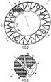
- a filter element 10 according to an embodiment represented in Figs. 1 and 2 has an internal face 20, an external face 21, a filtering mesh 22, two concentric circular edges, respectively an inner edge 24 and an outer edge 26 between which said filtering mesh 22 extends.
- the concentric circular edges 24, 26 are circular about a central axis X, hereafter referred to as defining an axial direction.
- the inner edge 24 mainly extends in a plane which is perpendicular to the axial direction X, i.e. a radial plane.
- the outer edge 26 mainly extends in a plane which is perpendicular to the axial direction X, i.e. a radial plane.
- the diameter of the outer edge 26 is about 300 mm.
- other diameters are possible, including, for example diameters in the range from about 100 mm to about 600 mm.
- the filter element 10 comprises radial ribs 28 provided at least on the internal face 20.
- radial ribs 28 are provided on the external face 21 too.
- the radial ribs 28 extend between the inner edge 24 and the outer edge 26, in the radial direction.
- the radial ribs 28 are regularly distributed circumferentially in order to form sectors on said internal face 20, as shown in Fig. 1 .
- further radial ribs 28 are regularly distributed circumferentially in order to form sectors on said external face 21, as shown in Fig. 2 .
- the radial ribs 28 on the internal face 20 and on the external face 21 face one another on opposite sides of the filtering mesh 22. In other words, the radial ribs 28 on the internal face 20 and on the external face 21 are in axial correspondence with one another.
- the inner edge 24 has passages 30 respectively communicating with corresponding ones of the sectors.
- the passages 30 are provided as notches or cutouts in the inner edge 24.
- the passages 30 are provided between consecutive radial ribs 28.
- the passages 30 are provided on the internal face 20.
- the outer edge 26 has passages 32 respectively communicating with corresponding ones of the sectors.
- the passages 32 are provided as notches or cutouts in the outer edge 26.
- the passages 32 are provided between consecutive radial ribs 28.
- the passages 32 are provided on the external face 20.
- Holes 34 for passing assembly rods are defined in the vicinity of the outer edge 26 of each filter element, and they are formed by molding the same material that defines the circular edges 24, 26 and the radial ribs 28.
- Male and female bushings 36 are arranged around these holes 34, e.g. in a radial rib 28, for indexing two filter elements 10 relative to each other.
- each filter element 10 is divided into sixteen sectors and has four holes 34 with bushings regularly spaced apart circumferentially.
- the filter element can have less or more sectors.
- a filter element having an outer diameter of 100 to 150 mm may have 8 to 12 sectors, and a filter element having an outer diameter of 500 to 600 mm may have 20 to 24 sectors.
- the filter elements 10 may be manufactured by molding around the filtering mesh 22. In other words, they may be manufactured by injection molding or similar, wherein the filtering mesh forms an insert in the mold.
- the molded portions may be made of metal (e.g. an aluminum alloy) or of plastics material, especially polymers.
- the radial ribs 28 and the inner and outer edges 24, 26 may be coated in elastomer in order to avoid leaks between filter elements 10.
- liquid to be filtered e.g. oil or water
- a passage 30 of the inner edge 24 of a filter element 10 cross the filtering mesh 22 to pass from the internal face 20 to the external face 21, whereby the liquid is filtered, and flow out of the filter element 10 through a passage 32 of the outer edge 26.
- the opposite flow direction is possible as well.
- each one of the sectors is provided with at least one reinforcing rib 40 connecting a radial rib 28 to the outer edge 26.
- Said reinforcing rib 40 has a portion that is inclined, when viewed in the radial plane in which the outer edge 26 extends, with respect to the radial rib 28 and to the outer edge 26.
- the reinforcing rib 40 has first and second inclined portions 42a, 42b and a radial portion 44.
- the first and second inclined portions 42a, 42b are respectively connected to the radial ribs 28 defining the sector, and to the radial portion 44.
- the radial portion 44 is connected to the outer edge 26.
- the radial portion 44 extends in the radial direction.
- the second inclined portion 42b may have all or part of the features of the first inclined portion 42a.
- the first and second inclined portions 42a, 42b are symmetric about the radial portion 44 to which they are connected.
- the first and second inclined portions may be asymmetrical about such radial portion.
- reinforcing ribs 40 are also provided on the external face 21.
- the reinforcing ribs 40 on the internal face 20 and on the external face 21 face one another on opposite sides of the filtering mesh 22 so as to decrease pressure losses.
- Features detailed hereafter as to the first inclined portion 42a on the internal face 20 may apply to the inclined portions on the external face 21.
- the first inclined portion 42a is rectilinear but it could also be curved, provided that it includes a portion that is inclined, when viewed in the plane in which the outer edge 26 extends, with respect to the radial rib 28 and to the outer edge 26.
- a distance D between the radial rib 28 and the first inclined portion 42a of the reinforcing rib 40, measured in the circumferential direction, increases towards the outer edge 26.
- the first inclined portion 42a and the radial rib 28 to which it is connected form an acute angle which opens towards the outer edge 26.
- the radial portion 44 of the reinforcing rib 40 is rectilinear. Note that, even though a rectilinear radial portion is preferred, other alternatives are also possible.
- the radial portion 44 and the first inclined portion 42a are connected so as to form an obtuse angle.
- the inclined portion and the radial rib When viewed in the plane in which the outer edge extends, the inclined portion and the radial rib form an angle from 5° to 85°. In the present embodiment, the angle is about 30°.
- the first and second inclined portions 42a, 42b are connected to each other so as to form a connecting portion 42 connecting the two consecutive radial ribs 28 between which the sector is formed.
- the first and second inclined portions 42a, 42b form respective branches of the connecting portion 42, each branch being connected to a radial rib 28 at a connection zone (respectively 42a' and 42b') and the two branches joining up at the joining zone 42' where they are also connected to the radial portion 44.
- said connecting portion 42 has the general shape of a V.
- the reinforcing rib has the general form of a Y.
- the two inclined branches of the Y are formed by the first and second inclined portions 42a, 42b forming the connecting portion 42.
- connection zones 42a' and 42b' are radially closer to the inner edge 24 than the joining zone 42'.
- the connecting portion formed by the first and second inclined portions may have a shape other than a V, for example a U shape.
- the filter element may have one or more connecting portions 142, having first and second inclined portions 142a and 142b, which are curved from their joining zone 142' to their respective connection zones 142a' and 142b'.
- This figure also shows the filter element having first and second inclined portions 242a and 242b, having rectilinear parts close to their connection zones 242a' and 242b', but having curved parts close to their joining zone 242'.
- the connecting portion has a concave shape, of which the concavity is turned towards the inner edge, from which the flow of fluid normally comes.
- each sector comprises two passages 32 in the outer edge 26.
- the radial portion 44 may be connected to the outer edge 26 between said two passages 32.
- each sector may comprise only one passage 32 in the outer edge 26, or more than two passages 32.
- the reinforcing rib 40 may comprise an enlarged portion 46, e.g. at the intersection of the radial portion 44 and the first and second inclined portions 42a, 42b.
- the enlarged portion 46 may be used for labeling purposes.
- the reinforcing rib 40 divides the filtering mesh surface of the sector in substantially equal areas.
- Figure 3 shows a detail of Fig. 1 .
- the reinforcing ribs may for some embodiments be connected to the radial ribs at similar radial locations, i.e. at a similar distance from the axial center of the filter element, in the embodiment shown in Fig. 3 , the reinforcing ribs 40 extending on either sides of one of the radial ribs 28 are connected to said one radial rib 28 at different locations in the radial direction.
- Fig. 3 shows a radial rib 28 compartmenting two adjacent sectors on the internal face 20. A first inclined portion 42a of one of the sectors and a second inclined portion 42b of the other one of the sectors are connected to the radial rib 28.
- the first inclined portion 42a and the second inclined portion 42b are connected to the radial rib 28 at different locations in the radial direction.
- a connection zone 42a' between the first inclined portion 42a and the radial rib 28 is closer to the outer edge 26 and farther from the inner edge 24 than a connection zone 42b' between the second inclined portion 42b and the radial rib 28.
- the filter elements 10 are configured to be assembled against each other so that their respective internal faces 20 face each other so as to define a space between them. Said space is circumferentially compartmented by the contacting radial ribs 28 of said internal faces. On the other hand, the radial ribs 28 provided on the external face 21 do not have to contact one another. Compartmenting sectors on the side of the filtering mesh 22 on which non-filtered liquid is introduced enables de-clogging the filtering mesh 22 by backwashing, as is known per se in the art.
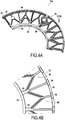
- a filter 100 is made by assembling together at least two filter elements 10, as shown in Fig. 4A . To obtain a filter of desired filter capacity, it suffices to stack and assemble together a desired number of individual filters 100 like the filter shown in Fig. 4A .
- the reinforcing ribs 40 extending on either sides of one of the radial ribs 28 are connected to said one radial rib 28 at different locations in the radial direction. Thanks to this feature, when two filter elements 10 are assembled against each other so that their respective internal faces 20 face each other, the reinforcing ribs 40 of the respective filter elements 10 do not entirely face each other in the axial direction. That is, when two filter elements 10 are assembled against each other so that their respective internal faces 20 face each other, the reinforcing ribs 40 of facing sectors of the respective filter elements 10 are shifted with respect to each other in a radial plane. This shift is particularly visible in Fig. 4B .
- the reinforcing ribs of the adjacent filter elements may have at least parts which do not overlap axially, which facilitates the flow of fluid.
- the radial length of the radial portion 44 of a reinforcing rib 40 may be longer than the radial length of the radial portion 44 of the reinforcing rib 40 of the adjacent sector (see e.g. Fig. 1 ).
- a shorter radial portion 44 axially faces a longer radial portion 44.
- the reinforcing ribs 40 help the filtering mesh 22 withstand the pressure of the fluid to be filtered.
- An optimal arrangement of the reinforcing ribs 40 enables to increase the fluid flow through the filter.
- the reinforcing ribs 40 contribute to stiffening the filter element 10.
- Figure 5 is a partial section view of the filter element 10 in plane V-V of Fig. 2 , i.e. through a radial rib 28 of the filter element 10.
- the internal face 20 and the external face 21 are separated by the filtering mesh 22.
- the thickness of the radial rib 28, in the axial direction is constant on the external face 21.
- the thickness of the radial rib 28, in the axial direction decreases from the inner edge 24 to the outer edge 26, on the external face 21.
- the inner edge 24 and the outer edge 26 are axially limited by two parallel radial planes.
- the filtering mesh 22 has a conical shape, or frustoconical shape, about the axial direction X of the filter element 10.
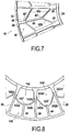
- Fig. 6 is a partial section view of the filter element 10 in plane VI-VI of Fig. 2 , i.e. through a passage 30 of the inner edge 24 and a passage 32 of the outer edge 26.
- a thickness of the reinforcing rib 40 is less than a thickness of the radial rib 28.
- the thickness of the connection zones 42a', 42b' of the first and second inclined portions 42a, 42b decreases from the thickness of the radial rib 28.
- the thickness of the first inclined portion 42a is constant.
- Fig. 6 shows that on the external face 21, a thickness of the reinforcing rib 40 (from which only the first inclined portion 42a is illustrated in Fig. 6 ), measured in the axial direction, is equal to a thickness of the radial rib 28.
- reference sign EI stands for the axial thickness of the inner edge 24 at a passage
- reference sign EO stands for the axial thickness of the outer edge 26 at a passage 32
- reference sign PI stands for the axial distance between the end portion of the filtering mesh 22 which is the closest to the central axis X and the closest edge of the passage 30 of the inner edge
- reference sign PO stands for the axial distance between the end portion of the filtering mesh 22 which is the farthest from the central axis X and the closest edge of the passage 32 of the outer edge 26.
- the filtering mesh 22 Since the filtering mesh 22 has a conical shape, the respective distances PI and PO between the filtering mesh 22 and the passages 30, 32 are increased with respect to that in filter elements wherein the filtering mesh is plane. Thus, the filtering mesh 22 is better held by the inner and outer edges 24, 26. This may even enable to increase the axial dimension of the passages 30, 32, so as to configure the filter element 10 to process greater flow rates.
- the filtering mesh 22 is inserted in the inner edge 24 at a location situated between 40% and 60% of the axial thickness EI of the inner edge 24 at a passage 30.
- the ratio PI/EI is between 40% and 60%.
- the filtering mesh 22 is inserted in the outer edge 26 at a location situated between 40% and 60% of the axial thickness EO of the outer edge 26 at a passage 32.
- the ratio PO/EO is between 40% and 60%.
- the filtering mesh 22 is tightly held by the inner and outer edges 24, 26, it is possible to make the radial ribs 28 and the reinforcing ribs 40 thinner than in prior art filter elements, and not to connect a reinforcing rib 40 to the inner edge 24.
- the proposed arrangement of the reinforcing ribs 40 including an inclined portion 42a, 42b minimizes the surface of the filtering mesh 22 which is not available for filtering.
- the ratio of the filtering mesh surface available for filtering to the total filtering mesh surface is at least 75%.
- the reinforcing rib 40 comprises two first inclined portions 42a, two second inclined portions 42b and two radial portions 44.
- One first inclined portion 42a and one second inclined portion 42b are connected to one radial portion 44 as previously described, e.g. in the general form of a Y.
- Another first inclined portion 42a and another second inclined portion 42b are connected to form of a Y.
- the two radial portions 44 are connected to each other so as to be aligned in the radial direction.
- the reinforcing rib comprises two connecting portions, each having two branches respectively formed by the first and the second inclined portions 42 a and 42b, and two radial portions 44 respectively extending from the outer edge to the joining zone 42' of the branches of the radially outer connecting portion, and from said joining zone and the joining zone of the branches of the radially inner connecting portion.
- the reinforcing rib 40 substantially has the general shape of two Ys one above the other, or the general shape of a fishbone.
- the two first inclined portions 42a do not have the same inclination angle with respect to the outer edge 26 and to the radial ribs 28. Their respective inclinations are determined such that the reinforcing rib 40 divides the filtering mesh surface of the sector in substantially equal areas.
- FIG. 9 illustrates a stack 102 comprising a plurality of filter elements stacked along an axis X.
- Filter elements 10 are assembled in pairs with respective identical, similar or complementary filter elements 10, as previously described. In each pair, filter elements 10 are arranged one against the other, so that their respective internal faces 20 face each other and the contacting radial ribs 28 of said respective internal faces 20 partition the space between said internal faces 20.
- Assembly rods 104 are inserted in the holes 34 of the filter elements 10, thereby ensuring alignment and axial correspondence of the filter elements 10.
- a filter 100 is shown in perspective in Fig. 10 .
- the filter 100 comprises a carter 110 and a stack 102 of filter elements is arranged within the carter 110.
- the filter 100 comprises a plurality of filter elements 10, said filter elements being stacked along the axis X.
- the filter 100 comprises two inlet portions 112 and two outlet portions 114.
- the filter 100 may comprise one or more inlet portions 112, and/or one or more outlet portions 114.
- the inlet portions 112 are fluidly connected to the passages 30 of the inner edges 24 of the filter elements 10, while the outlet portions 114 are fluidly connected to the passages 32 of the outer edges 26.
- the flow direction within the carter 110 and the stack 102 may be reversed.
- the stack 102 of filter elements is fastened to the carter 110 in a conventional manner.
Landscapes
- Chemical & Material Sciences (AREA)
- Chemical Kinetics & Catalysis (AREA)
- Filtering Of Dispersed Particles In Gases (AREA)
- Filtration Of Liquid (AREA)
Claims (19)
- Filterelement (10), das eine Innenfläche (20), eine Außenfläche (21), ein Filterungssieb (22), zwei konzentrische kreisförmige Kanten, jeweils eine Innenkante (24) und eine Außenkante (26), zwischen denen sich das Filterungssieb (22) erstreckt, und radiale Rippen (28), die wenigstens auf der Innenfläche (20) bereitgestellt sind, hat, wobei sich die radialen Rippen (28) zwischen den konzentrischen Kanten (24, 26) erstrecken und umlaufend verteilt sind, um Sektoren auf der Innenfläche (20) zu bilden, wobei das Filterelement (10) dafür konfiguriert ist, so gegen ein entsprechendes Filterelement montiert zu werden, dass die Innenfläche (20) zu dem entsprechenden Filterelement zeigt, und die radialen Rippen (28), welche die Sektoren begrenzen, wirken, um umlaufend Abteilungen in einem Raum zwischen der Innenfläche und dem entsprechenden Filterelement zu bilden, wobei die Innenkante (24) Durchgänge (30) hat, die jeweils mit entsprechenden der Sektoren in Verbindung stehen, dadurch gekennzeichnet, dass wenigstens einige der Sektoren, vorzugsweise die meisten der Sektoren oder sogar alle Sektoren jeweils mit wenigstens einer Verstärkungsrippe (40) versehen sind, die eine radiale Rippe (28) mit der Außenkante (26) verbindet, und dadurch, dass die Verstärkungsrippe (40) einen geneigten Abschnitt (42a, 42b) hat, der, wenn in einer radialen Ebene betrachtet, einen Winkel ungleich null in Bezug auf die radiale Rippe (28) und in Bezug auf die Außenkante (26) bildet.
- Filterelement nach Anspruch 1, wobei ein Abstand (D) zwischen der radialen Rippe (28) und dem geneigten Abschnitt (42, 42b) der Verstärkungsrippe (40), gemessen in der Umfangsrichtung, zu der Außenkante (26) hin zunimmt.
- Filterelement nach Anspruch 1 oder 2, wobei, wenn in der radialen Ebene betrachtet, in der sich die Außenkante (26) erstreckt, der geneigte Abschnitt (42a, 42b) und die radiale Rippe (28) einen Winkel bilden, der größer als 5°, vorzugsweise größer als 10°, vorzugsweise größer als 15° und kleiner als 85°, vorzugsweise kleiner als 70°, vorzugsweise kleiner als 60°, ist.
- Filterelement nach einem der Ansprüche 1 bis 3, wobei die Verstärkungsrippe (40) einen Verbindungsabschnitt (42) umfasst, der die zwei aufeinanderfolgenden radialen Rippen (28) verbindet, die den Sektor begrenzen, in dem die Verstärkungsrippe geformt ist, wobei der Verbindungsabschnitt (42) zwei Zweige (42a, 42b) hat, die jeweils an einer Verbindungszone (42a', 42b') mit einer der zwei aufeinanderfolgenden radialen Rippen (28) verbunden sind, wobei die Zweige an einer Verschmelzungszone (42') miteinander verschmelzen.
- Filterelement nach Anspruch 4, wobei die Verbindungszonen (42a', 42b') in Radialrichtung näher zu der Innenkante sind als die Verschmelzungszone (42').
- Filterelement nach Anspruch 4 oder 5, wobei der Verbindungsabschnitt (42) die allgemeine Form eines V oder eines U hat.
- Filterelement nach einem der Ansprüche 1 bis 6, wobei die Verstärkungsrippe (40) die allgemeine Form eines Y hat.
- Filterelement nach einem der Ansprüche 4 bis 6, wobei die Verstärkungsrippe (40) einen ersten und einen zweiten Verbindungsabschnitt (42), wobei jeder zwei Zweige (42a, 42b) hat, die jeweils mit einer der zwei aufeinanderfolgenden radialen Rippen (28) verbunden sind, und zwei radiale Abschnitte (44) umfasst, wobei sich der erste radiale Abschnitt zwischen der Außenkante und der Verschmelzungszone (42') der Zweige des ersten Verbindungsabschnitts erstreckt und sich der zweite radiale Abschnitt zwischen der Verschmelzungszone der Zweige des ersten Verbindungsabschnitts und der Verschmelzungszone (42') der Zweige des zweiten Verbindungsabschnitts erstreckt.
- Filterelement nach einem der Ansprüche 1 bis 8, wobei die Verstärkungsrippe (40) nahe einem Fluiddurchgang (32) derselben in der Umfangsrichtung mit der Außenkante (26) verbunden ist.
- Filterelement nach einem der Ansprüche 1 bis 9, wobei die Verstärkungsrippen (40), die sich auf beiden Seiten einer der radialen Rippen (28) erstrecken, an unterschiedlichen Positionen (42a', 42b') in der Radialrichtung mit der einen radialen Rippe verbunden sind.
- Filterelement nach einem der Ansprüche 1 bis 10, wobei das Filterungssieb (22) eine konische Form hat.
- Filterelement nach einem der Ansprüche 1 bis 11, wobei das Filterungssieb (22) an einer Position (PI), die sich zwischen 40 % und 60 % der axialen Dicke (EI) der Innenkante (24) an einem Durchgang (30) befindet, an der Innenkante (24) befestigt ist.
- Filterelement nach einem der Ansprüche 1 bis 12, wobei die Verstärkungsrippe (40) die Filterungssiebfläche des Sektors in Bereiche von im Wesentlichen ähnlicher Größe teilt.
- Filterelement nach einem der Ansprüche 1 bis 13, wobei das Verhältnis der zur Filterung verfügbaren Filterungssiebfläche zu der gesamten Filterungssiebfläche wenigstens 70 %, vorzugsweise wenigstens 75 %, beträgt.
- Filterelement nach einem der Ansprüche 1 bis 14, wobei radiale Rippen (28) ferner auf der Außenfläche (21) bereitgestellt werden, wobei sich die radialen Rippen zwischen den zwei konzentrischen kreisförmigen Kanten (24, 26) erstrecken und regelmäßig in Umfangsrichtung verteilt sind, um Sektoren auf der Außenfläche (21) zu bilden, und wobei sich die radialen Rippen (28) auf der Innenfläche (20) in axialer Entsprechung mit den radialen Rippen auf der Außenfläche (21) befinden.
- Filterelement nach einem der Ansprüche 1 bis 15, wobei die radialen Rippen (28) und/oder die Verstärkungsrippe (40) aus Polymer hergestellt sind.
- Filterelement nach einem der Ansprüche 1 bis 16, wobei das Filterungssieb (22) frei ist von Stützsieb.
- Paar von Filterelementen nach einem der Ansprüche 1 bis 17, die so gegeneinander angeordnet sind, dass ihre jeweiligen Innenflächen zueinander zeigen und die berührenden radialen Rippen (28) der jeweiligen Innenflächen den Raum zwischen den Innenflächen unterteilen.
- Filter (100), der mehrere Filterelemente nach einem der Ansprüche 1 bis 18 umfasst, wobei die Filterelemente entlang einer Achse (X) gestapelt sind.
Priority Applications (10)
| Application Number | Priority Date | Filing Date | Title |
|---|---|---|---|
| ES16305082.6T ES2688446T3 (es) | 2016-01-28 | 2016-01-28 | Elemento de filtro y filtro que comprende al menos dos elementos de filtro |
| EP16305082.6A EP3199219B1 (de) | 2016-01-28 | 2016-01-28 | Filterelement und filter mit mindestens zwei filterelementen |
| DK16305082.6T DK3199219T3 (en) | 2016-01-28 | 2016-01-28 | FILTER ELEMENTS AND FILTERS CONTAINING AT LEAST TWO FILTER ELEMENTS |
| PL16305082T PL3199219T3 (pl) | 2016-01-28 | 2016-01-28 | Element filtrujący i filtr zawierający co najmniej dwa elementy filtrujące |
| JP2018558486A JP6700428B2 (ja) | 2016-01-28 | 2017-01-26 | フィルタエレメント、および少なくとも2つのフィルタエレメントを備えるフィルタ |
| US16/061,629 US10960327B2 (en) | 2016-01-28 | 2017-01-26 | Filter element and filter comprising at least two filter elements |
| KR1020187024363A KR102176915B1 (ko) | 2016-01-28 | 2017-01-26 | 필터 요소 및 2개 이상의 필터 요소를 포함하는 필터 |
| PCT/EP2017/051685 WO2017129701A1 (en) | 2016-01-28 | 2017-01-26 | Filter element and filter comprising at least two filter elements |
| CN201780008927.1A CN108601995B (zh) | 2016-01-28 | 2017-01-26 | 过滤器元件及包括至少两个过滤器元件的过滤器 |
| RU2018130846A RU2686911C1 (ru) | 2016-01-28 | 2017-01-26 | Фильтрующий элемент и фильтр, содержащий по меньшей мере два фильтрующих элемента |
Applications Claiming Priority (1)
| Application Number | Priority Date | Filing Date | Title |
|---|---|---|---|
| EP16305082.6A EP3199219B1 (de) | 2016-01-28 | 2016-01-28 | Filterelement und filter mit mindestens zwei filterelementen |
Publications (2)
| Publication Number | Publication Date |
|---|---|
| EP3199219A1 EP3199219A1 (de) | 2017-08-02 |
| EP3199219B1 true EP3199219B1 (de) | 2018-08-08 |
Family
ID=55451144
Family Applications (1)
| Application Number | Title | Priority Date | Filing Date |
|---|---|---|---|
| EP16305082.6A Active EP3199219B1 (de) | 2016-01-28 | 2016-01-28 | Filterelement und filter mit mindestens zwei filterelementen |
Country Status (10)
| Country | Link |
|---|---|
| US (1) | US10960327B2 (de) |
| EP (1) | EP3199219B1 (de) |
| JP (1) | JP6700428B2 (de) |
| KR (1) | KR102176915B1 (de) |
| CN (1) | CN108601995B (de) |
| DK (1) | DK3199219T3 (de) |
| ES (1) | ES2688446T3 (de) |
| PL (1) | PL3199219T3 (de) |
| RU (1) | RU2686911C1 (de) |
| WO (1) | WO2017129701A1 (de) |
Families Citing this family (6)
| Publication number | Priority date | Publication date | Assignee | Title |
|---|---|---|---|---|
| ES2718238T3 (es) | 2016-06-10 | 2019-06-28 | Alfa Laval Corp Ab | Unidad de filtrado con retrolavado automático |
| WO2019106673A1 (en) * | 2017-11-29 | 2019-06-06 | Maagan Filtration Aca Ltd. | Filtration system |
| EP3753622B1 (de) * | 2019-06-17 | 2022-04-13 | Gerum GmbH | Filtereinheit und filtrationsanlage |
| EP3782711B1 (de) | 2019-08-19 | 2022-04-27 | Alfa Laval Moatti | Filtereinheit mit verbesserter abdeckungsanordnung |
| CN112044182B (zh) * | 2020-09-24 | 2024-10-18 | 珠海亿泰科技有限公司 | 一种滤芯连接适配装置 |
| DK4268924T3 (da) | 2022-04-26 | 2025-08-04 | Alfa Laval Moatti | Filterelement og filter, der omfatter mindst to filterelementer |
Family Cites Families (17)
| Publication number | Priority date | Publication date | Assignee | Title |
|---|---|---|---|---|
| US1812725A (en) * | 1927-08-27 | 1931-06-30 | Oliver United Filters Inc | Method of attaching filter cloth |
| US2088199A (en) | 1936-02-01 | 1937-07-27 | Stanley F Gleason | Filter |
| GB512972A (en) | 1937-03-27 | 1939-09-29 | Ig Farbenindustrie Ag | Improvements in filters |
| US2592527A (en) | 1945-12-07 | 1952-04-15 | Us Hoffman Machinery Corp | Filter |
| US2592849A (en) | 1948-05-12 | 1952-04-15 | Wipac Filtration Ltd | Filter |
| CH306628A (de) | 1951-09-29 | 1955-04-30 | Gmbh Robert Bosch | Filter, insbesondere für flüssige Kraftstoffe. |
| BE516316A (de) | 1952-02-23 | 1900-01-01 | ||
| US3079001A (en) | 1958-10-08 | 1963-02-26 | May Griffith | Mechanical filter assembly |
| CH386989A (fr) * | 1962-12-12 | 1965-01-31 | Brasco Sa | Filtre |
| JPS479395Y1 (de) * | 1969-02-22 | 1972-04-10 | ||
| JPS4732221Y1 (de) * | 1969-05-07 | 1972-09-28 | ||
| JPS479395U (de) | 1971-02-25 | 1972-10-04 | ||
| JPS4732221U (de) | 1971-04-23 | 1972-12-11 | ||
| IL74873A (en) | 1985-04-10 | 1990-07-12 | Drori Mordeki | Multiple disc type filter and disc construction useful therein |
| FR2779359B1 (fr) | 1998-06-05 | 2000-08-25 | Alfa Laval Moatti Snc | Element filtrant destine a etre utilise dans un dispositif de filtration |
| RU2166351C1 (ru) | 2000-03-29 | 2001-05-10 | Тимонин Александр Семенович | Дисковый фильтр |
| FR2964329B1 (fr) * | 2010-09-03 | 2012-09-28 | Alfa Laval Moatti | Filtre a decolmatage automatique |
-
2016
- 2016-01-28 PL PL16305082T patent/PL3199219T3/pl unknown
- 2016-01-28 DK DK16305082.6T patent/DK3199219T3/en active
- 2016-01-28 EP EP16305082.6A patent/EP3199219B1/de active Active
- 2016-01-28 ES ES16305082.6T patent/ES2688446T3/es active Active
-
2017
- 2017-01-26 JP JP2018558486A patent/JP6700428B2/ja active Active
- 2017-01-26 CN CN201780008927.1A patent/CN108601995B/zh active Active
- 2017-01-26 WO PCT/EP2017/051685 patent/WO2017129701A1/en not_active Ceased
- 2017-01-26 RU RU2018130846A patent/RU2686911C1/ru active
- 2017-01-26 KR KR1020187024363A patent/KR102176915B1/ko active Active
- 2017-01-26 US US16/061,629 patent/US10960327B2/en active Active
Non-Patent Citations (1)
| Title |
|---|
| None * |
Also Published As
| Publication number | Publication date |
|---|---|
| DK3199219T3 (en) | 2018-12-03 |
| WO2017129701A1 (en) | 2017-08-03 |
| EP3199219A1 (de) | 2017-08-02 |
| CN108601995A (zh) | 2018-09-28 |
| CN108601995B (zh) | 2021-03-12 |
| US10960327B2 (en) | 2021-03-30 |
| JP6700428B2 (ja) | 2020-05-27 |
| RU2686911C1 (ru) | 2019-05-06 |
| ES2688446T3 (es) | 2018-11-02 |
| KR102176915B1 (ko) | 2020-11-10 |
| KR20180101592A (ko) | 2018-09-12 |
| PL3199219T3 (pl) | 2019-01-31 |
| JP2019507012A (ja) | 2019-03-14 |
| US20180369722A1 (en) | 2018-12-27 |
Similar Documents
| Publication | Publication Date | Title |
|---|---|---|
| US10960327B2 (en) | Filter element and filter comprising at least two filter elements | |
| US4880537A (en) | Multiple disc type filter and disc construction useful therein | |
| EP0674931B1 (de) | Nebenring und Auflagenplatte für einen Filter und Verfahren zur Herstellung dieser Teile | |
| US4683060A (en) | Multiple-disc type filters | |
| US20060243653A1 (en) | Dialysis filter | |
| RU2585782C2 (ru) | Новая геометрия фильтрующих элементов | |
| JP6267244B2 (ja) | 濾過支持体の幾何学的形状及び膜 | |
| US8414769B2 (en) | Disc filter sector and disc filter | |
| US20130008848A1 (en) | Filter comprising stackable filter wafers with filtering channels on opposing sides of the wafers | |
| CN101675192A (zh) | 处理适用于造纸的纤维悬浮液的筛,尤其刚性筛的制造方法 | |
| CN103830976A (zh) | 用于过滤元件的支撑管 | |
| CN115427719B (zh) | 用于控制阀的三维曲折路径流量元件 | |
| JP2009189947A (ja) | スパイラル型流体分離素子 | |
| EP4268924B1 (de) | Filterelement und filter mit mindestens zwei filterelementen | |
| US11213769B2 (en) | Nozzles/screens used in the fluid processing units | |
| CN111228878B (zh) | 一种过滤叠片以及包括其的叠片式过滤器 | |
| JP7632141B2 (ja) | モジュール | |
| KR100323574B1 (ko) | 디스크형필터부재및디스크형필터시스템 | |
| KR20150089958A (ko) | 적층 플레이트 열교환기 | |
| KR102917092B1 (ko) | 고압 유체의 순차적 압력 및 속도 제어 시스템 | |
| EP3812685A1 (de) | Mittelkörper in spiralförmigem wärmetauscher |
Legal Events
| Date | Code | Title | Description |
|---|---|---|---|
| PUAI | Public reference made under article 153(3) epc to a published international application that has entered the european phase |
Free format text: ORIGINAL CODE: 0009012 |
|
| STAA | Information on the status of an ep patent application or granted ep patent |
Free format text: STATUS: THE APPLICATION HAS BEEN PUBLISHED |
|
| AK | Designated contracting states |
Kind code of ref document: A1 Designated state(s): AL AT BE BG CH CY CZ DE DK EE ES FI FR GB GR HR HU IE IS IT LI LT LU LV MC MK MT NL NO PL PT RO RS SE SI SK SM TR |
|
| AX | Request for extension of the european patent |
Extension state: BA ME |
|
| STAA | Information on the status of an ep patent application or granted ep patent |
Free format text: STATUS: REQUEST FOR EXAMINATION WAS MADE |
|
| 17P | Request for examination filed |
Effective date: 20171005 |
|
| RBV | Designated contracting states (corrected) |
Designated state(s): AL AT BE BG CH CY CZ DE DK EE ES FI FR GB GR HR HU IE IS IT LI LT LU LV MC MK MT NL NO PL PT RO RS SE SI SK SM TR |
|
| GRAP | Despatch of communication of intention to grant a patent |
Free format text: ORIGINAL CODE: EPIDOSNIGR1 |
|
| STAA | Information on the status of an ep patent application or granted ep patent |
Free format text: STATUS: GRANT OF PATENT IS INTENDED |
|
| INTG | Intention to grant announced |
Effective date: 20180301 |
|
| RAP1 | Party data changed (applicant data changed or rights of an application transferred) |
Owner name: ALVA LAVAL MOATTI SAS Owner name: ALFA LAVAL CORPORATE AB |
|
| RAP1 | Party data changed (applicant data changed or rights of an application transferred) |
Owner name: ALFA LAVAL CORPORATE AB Owner name: ALFA LAVAL MOATTI SAS |
|
| GRAS | Grant fee paid |
Free format text: ORIGINAL CODE: EPIDOSNIGR3 |
|
| GRAJ | Information related to disapproval of communication of intention to grant by the applicant or resumption of examination proceedings by the epo deleted |
Free format text: ORIGINAL CODE: EPIDOSDIGR1 |
|
| GRAL | Information related to payment of fee for publishing/printing deleted |
Free format text: ORIGINAL CODE: EPIDOSDIGR3 |
|
| STAA | Information on the status of an ep patent application or granted ep patent |
Free format text: STATUS: REQUEST FOR EXAMINATION WAS MADE |
|
| GRAR | Information related to intention to grant a patent recorded |
Free format text: ORIGINAL CODE: EPIDOSNIGR71 |
|
| STAA | Information on the status of an ep patent application or granted ep patent |
Free format text: STATUS: GRANT OF PATENT IS INTENDED |
|
| INTC | Intention to grant announced (deleted) | ||
| INTG | Intention to grant announced |
Effective date: 20180522 |
|
| GRAA | (expected) grant |
Free format text: ORIGINAL CODE: 0009210 |
|
| STAA | Information on the status of an ep patent application or granted ep patent |
Free format text: STATUS: THE PATENT HAS BEEN GRANTED |
|
| AK | Designated contracting states |
Kind code of ref document: B1 Designated state(s): AL AT BE BG CH CY CZ DE DK EE ES FI FR GB GR HR HU IE IS IT LI LT LU LV MC MK MT NL NO PL PT RO RS SE SI SK SM TR |
|
| REG | Reference to a national code |
Ref country code: GB Ref legal event code: FG4D |
|
| REG | Reference to a national code |
Ref country code: CH Ref legal event code: EP Ref country code: AT Ref legal event code: REF Ref document number: 1026341 Country of ref document: AT Kind code of ref document: T Effective date: 20180815 |
|
| REG | Reference to a national code |
Ref country code: IE Ref legal event code: FG4D |
|
| REG | Reference to a national code |
Ref country code: DE Ref legal event code: R096 Ref document number: 602016004608 Country of ref document: DE |
|
| REG | Reference to a national code |
Ref country code: SE Ref legal event code: TRGR |
|
| REG | Reference to a national code |
Ref country code: ES Ref legal event code: FG2A Ref document number: 2688446 Country of ref document: ES Kind code of ref document: T3 Effective date: 20181102 |
|
| REG | Reference to a national code |
Ref country code: NL Ref legal event code: FP |
|
| REG | Reference to a national code |
Ref country code: DK Ref legal event code: T3 Effective date: 20181128 |
|
| REG | Reference to a national code |
Ref country code: LT Ref legal event code: MG4D |
|
| PG25 | Lapsed in a contracting state [announced via postgrant information from national office to epo] |
Ref country code: LT Free format text: LAPSE BECAUSE OF FAILURE TO SUBMIT A TRANSLATION OF THE DESCRIPTION OR TO PAY THE FEE WITHIN THE PRESCRIBED TIME-LIMIT Effective date: 20180808 Ref country code: RS Free format text: LAPSE BECAUSE OF FAILURE TO SUBMIT A TRANSLATION OF THE DESCRIPTION OR TO PAY THE FEE WITHIN THE PRESCRIBED TIME-LIMIT Effective date: 20180808 Ref country code: IS Free format text: LAPSE BECAUSE OF FAILURE TO SUBMIT A TRANSLATION OF THE DESCRIPTION OR TO PAY THE FEE WITHIN THE PRESCRIBED TIME-LIMIT Effective date: 20181208 Ref country code: NO Free format text: LAPSE BECAUSE OF FAILURE TO SUBMIT A TRANSLATION OF THE DESCRIPTION OR TO PAY THE FEE WITHIN THE PRESCRIBED TIME-LIMIT Effective date: 20181108 |
|
| PG25 | Lapsed in a contracting state [announced via postgrant information from national office to epo] |
Ref country code: LV Free format text: LAPSE BECAUSE OF FAILURE TO SUBMIT A TRANSLATION OF THE DESCRIPTION OR TO PAY THE FEE WITHIN THE PRESCRIBED TIME-LIMIT Effective date: 20180808 Ref country code: HR Free format text: LAPSE BECAUSE OF FAILURE TO SUBMIT A TRANSLATION OF THE DESCRIPTION OR TO PAY THE FEE WITHIN THE PRESCRIBED TIME-LIMIT Effective date: 20180808 Ref country code: AL Free format text: LAPSE BECAUSE OF FAILURE TO SUBMIT A TRANSLATION OF THE DESCRIPTION OR TO PAY THE FEE WITHIN THE PRESCRIBED TIME-LIMIT Effective date: 20180808 |
|
| REG | Reference to a national code |
Ref country code: GR Ref legal event code: EP Ref document number: 20180402828 Country of ref document: GR Effective date: 20190225 |
|
| PG25 | Lapsed in a contracting state [announced via postgrant information from national office to epo] |
Ref country code: CZ Free format text: LAPSE BECAUSE OF FAILURE TO SUBMIT A TRANSLATION OF THE DESCRIPTION OR TO PAY THE FEE WITHIN THE PRESCRIBED TIME-LIMIT Effective date: 20180808 Ref country code: EE Free format text: LAPSE BECAUSE OF FAILURE TO SUBMIT A TRANSLATION OF THE DESCRIPTION OR TO PAY THE FEE WITHIN THE PRESCRIBED TIME-LIMIT Effective date: 20180808 Ref country code: RO Free format text: LAPSE BECAUSE OF FAILURE TO SUBMIT A TRANSLATION OF THE DESCRIPTION OR TO PAY THE FEE WITHIN THE PRESCRIBED TIME-LIMIT Effective date: 20180808 |
|
| REG | Reference to a national code |
Ref country code: DE Ref legal event code: R097 Ref document number: 602016004608 Country of ref document: DE |
|
| PG25 | Lapsed in a contracting state [announced via postgrant information from national office to epo] |
Ref country code: SK Free format text: LAPSE BECAUSE OF FAILURE TO SUBMIT A TRANSLATION OF THE DESCRIPTION OR TO PAY THE FEE WITHIN THE PRESCRIBED TIME-LIMIT Effective date: 20180808 Ref country code: SM Free format text: LAPSE BECAUSE OF FAILURE TO SUBMIT A TRANSLATION OF THE DESCRIPTION OR TO PAY THE FEE WITHIN THE PRESCRIBED TIME-LIMIT Effective date: 20180808 |
|
| PLBE | No opposition filed within time limit |
Free format text: ORIGINAL CODE: 0009261 |
|
| STAA | Information on the status of an ep patent application or granted ep patent |
Free format text: STATUS: NO OPPOSITION FILED WITHIN TIME LIMIT |
|
| 26N | No opposition filed |
Effective date: 20190509 |
|
| PG25 | Lapsed in a contracting state [announced via postgrant information from national office to epo] |
Ref country code: SI Free format text: LAPSE BECAUSE OF FAILURE TO SUBMIT A TRANSLATION OF THE DESCRIPTION OR TO PAY THE FEE WITHIN THE PRESCRIBED TIME-LIMIT Effective date: 20180808 Ref country code: MC Free format text: LAPSE BECAUSE OF FAILURE TO SUBMIT A TRANSLATION OF THE DESCRIPTION OR TO PAY THE FEE WITHIN THE PRESCRIBED TIME-LIMIT Effective date: 20180808 |
|
| REG | Reference to a national code |
Ref country code: CH Ref legal event code: PL |
|
| PG25 | Lapsed in a contracting state [announced via postgrant information from national office to epo] |
Ref country code: LU Free format text: LAPSE BECAUSE OF NON-PAYMENT OF DUE FEES Effective date: 20190128 |
|
| REG | Reference to a national code |
Ref country code: IE Ref legal event code: MM4A |
|
| PG25 | Lapsed in a contracting state [announced via postgrant information from national office to epo] |
Ref country code: FR Free format text: LAPSE BECAUSE OF NON-PAYMENT OF DUE FEES Effective date: 20190131 |
|
| PG25 | Lapsed in a contracting state [announced via postgrant information from national office to epo] |
Ref country code: LI Free format text: LAPSE BECAUSE OF NON-PAYMENT OF DUE FEES Effective date: 20190131 Ref country code: CH Free format text: LAPSE BECAUSE OF NON-PAYMENT OF DUE FEES Effective date: 20190131 |
|
| PG25 | Lapsed in a contracting state [announced via postgrant information from national office to epo] |
Ref country code: IE Free format text: LAPSE BECAUSE OF NON-PAYMENT OF DUE FEES Effective date: 20190128 |
|
| PG25 | Lapsed in a contracting state [announced via postgrant information from national office to epo] |
Ref country code: TR Free format text: LAPSE BECAUSE OF FAILURE TO SUBMIT A TRANSLATION OF THE DESCRIPTION OR TO PAY THE FEE WITHIN THE PRESCRIBED TIME-LIMIT Effective date: 20180808 |
|
| PG25 | Lapsed in a contracting state [announced via postgrant information from national office to epo] |
Ref country code: MT Free format text: LAPSE BECAUSE OF NON-PAYMENT OF DUE FEES Effective date: 20190128 Ref country code: PT Free format text: LAPSE BECAUSE OF FAILURE TO SUBMIT A TRANSLATION OF THE DESCRIPTION OR TO PAY THE FEE WITHIN THE PRESCRIBED TIME-LIMIT Effective date: 20181208 |
|
| REG | Reference to a national code |
Ref country code: AT Ref legal event code: UEP Ref document number: 1026341 Country of ref document: AT Kind code of ref document: T Effective date: 20180808 |
|
| PG25 | Lapsed in a contracting state [announced via postgrant information from national office to epo] |
Ref country code: CY Free format text: LAPSE BECAUSE OF FAILURE TO SUBMIT A TRANSLATION OF THE DESCRIPTION OR TO PAY THE FEE WITHIN THE PRESCRIBED TIME-LIMIT Effective date: 20180808 |
|
| PG25 | Lapsed in a contracting state [announced via postgrant information from national office to epo] |
Ref country code: HU Free format text: LAPSE BECAUSE OF FAILURE TO SUBMIT A TRANSLATION OF THE DESCRIPTION OR TO PAY THE FEE WITHIN THE PRESCRIBED TIME-LIMIT; INVALID AB INITIO Effective date: 20160128 |
|
| PG25 | Lapsed in a contracting state [announced via postgrant information from national office to epo] |
Ref country code: MK Free format text: LAPSE BECAUSE OF FAILURE TO SUBMIT A TRANSLATION OF THE DESCRIPTION OR TO PAY THE FEE WITHIN THE PRESCRIBED TIME-LIMIT Effective date: 20180808 |
|
| P01 | Opt-out of the competence of the unified patent court (upc) registered |
Effective date: 20230324 |
|
| PGFP | Annual fee paid to national office [announced via postgrant information from national office to epo] |
Ref country code: GB Payment date: 20251204 Year of fee payment: 11 |
|
| PGFP | Annual fee paid to national office [announced via postgrant information from national office to epo] |
Ref country code: FI Payment date: 20251230 Year of fee payment: 11 |
|
| PGFP | Annual fee paid to national office [announced via postgrant information from national office to epo] |
Ref country code: NL Payment date: 20251215 Year of fee payment: 11 |
|
| PGFP | Annual fee paid to national office [announced via postgrant information from national office to epo] |
Ref country code: BE Payment date: 20251223 Year of fee payment: 11 Ref country code: GR Payment date: 20251210 Year of fee payment: 11 |
|
| PGFP | Annual fee paid to national office [announced via postgrant information from national office to epo] |
Ref country code: SE Payment date: 20251210 Year of fee payment: 11 |
|
| PGFP | Annual fee paid to national office [announced via postgrant information from national office to epo] |
Ref country code: PL Payment date: 20251212 Year of fee payment: 11 |
|
| PGFP | Annual fee paid to national office [announced via postgrant information from national office to epo] |
Ref country code: BG Payment date: 20251215 Year of fee payment: 11 |
|
| PGFP | Annual fee paid to national office [announced via postgrant information from national office to epo] |
Ref country code: ES Payment date: 20260209 Year of fee payment: 11 |
|
| PGFP | Annual fee paid to national office [announced via postgrant information from national office to epo] |
Ref country code: DE Payment date: 20251203 Year of fee payment: 11 Ref country code: DK Payment date: 20260113 Year of fee payment: 11 |
|
| PGFP | Annual fee paid to national office [announced via postgrant information from national office to epo] |
Ref country code: AT Payment date: 20251230 Year of fee payment: 11 |
|
| PGFP | Annual fee paid to national office [announced via postgrant information from national office to epo] |
Ref country code: IT Payment date: 20251219 Year of fee payment: 11 |