EP3199301A1 - Chambre de combustion et appareil d'enfoncement - Google Patents
Chambre de combustion et appareil d'enfoncement Download PDFInfo
- Publication number
- EP3199301A1 EP3199301A1 EP16153619.8A EP16153619A EP3199301A1 EP 3199301 A1 EP3199301 A1 EP 3199301A1 EP 16153619 A EP16153619 A EP 16153619A EP 3199301 A1 EP3199301 A1 EP 3199301A1
- Authority
- EP
- European Patent Office
- Prior art keywords
- combustion chamber
- sealing ring
- angular position
- cylinder axis
- chamber wall
- Prior art date
- Legal status (The legal status is an assumption and is not a legal conclusion. Google has not performed a legal analysis and makes no representation as to the accuracy of the status listed.)
- Withdrawn
Links
Images

Classifications
-
- B—PERFORMING OPERATIONS; TRANSPORTING
- B25—HAND TOOLS; PORTABLE POWER-DRIVEN TOOLS; MANIPULATORS
- B25C—HAND-HELD NAILING OR STAPLING TOOLS; MANUALLY OPERATED PORTABLE STAPLING TOOLS
- B25C1/00—Hand-held nailing tools; Nail feeding devices
- B25C1/08—Hand-held nailing tools; Nail feeding devices operated by combustion pressure
-
- B—PERFORMING OPERATIONS; TRANSPORTING
- B25—HAND TOOLS; PORTABLE POWER-DRIVEN TOOLS; MANIPULATORS
- B25C—HAND-HELD NAILING OR STAPLING TOOLS; MANUALLY OPERATED PORTABLE STAPLING TOOLS
- B25C1/00—Hand-held nailing tools; Nail feeding devices
- B25C1/008—Safety devices
Definitions
- the invention relates to a combustion chamber and a tacker with such a combustion chamber.
- combustion chambers in particular of driving tools, which comprise a combustion chamber wall in the form of a cylinder axis defining a hollow cylinder, an adjustable inside the hollow cylinder relative to the combustion chamber wall along the cylinder axis and a seal, which in a radial direction relative to the cylinder axis on the one hand to the ground and on the other abuts the combustion chamber wall, for example, to seal a gap between the bottom and the combustion chamber wall.
- the sealing effect is usually achieved in that the seal consists of a soft sealant, for example of an elastomer.
- a sealing effect can also be achieved by using a hard sealant, for example a thermoplastic or a thermoset, or else a metal or an alloy, by virtue of the seal being capable of elastic deformation, that is to say of its external shape.
- the seal comprises a first sealing ring, which extends in the circumferential direction relative to the cylinder axis, with a first interruption. Due to the interruption, the rigidity of the sealing ring is reduced as such, so that the sealing ring as a whole elastically rests, for example, on the combustion chamber wall.
- a circumferentially extending second sealing ring with respect to the cylinder axis having a second interruption disposed along the circumferential direction opposite the first interruption.
- the opposing arrangement of the first and the second interruption is determined by means of a fixing device.
- the DE 102 26 878 A1 describes a driving tool for driving a nail into a workpiece in which a combustion chamber is charged with a fuel gas, wherein after a firing process, a driving piston is accelerated against the nail.
- the combustion chamber has an adjustable combustion chamber floor, wherein an adjusting rod is guided by means of a passage through a housing of the combustion chamber and is connected to the adjustable combustion chamber floor.
- the combustion chamber bottom is sealed by a circumferential seal against the combustion chamber wall.
- This object is achieved in a combustion chamber in which the first interruption has a first angular position along the circumferential direction and the second interruption has a second angular position along the circumferential direction, wherein the first angular position and the second angular position enclose an angle which is greater than 0 ° and is less than 180 °.
- the invention is based on the finding that when the first and second sealing rings are stuck together, it is not necessary to break the ice connecting the two sealing rings over the entire circumference of the sealing rings. Rather, it is sufficient to break the ice over a single peripheral portion between the first and the second interruption, so that the two interruptions are movable relative to each other.
- the mutual stiffening of the two sealing rings is then essentially already repealed.
- the shortening of a single circumferential portion between the two interruptions is sufficient to ensure a weak spot in the unwanted icing between the two sealing rings, so that a break-up of the ice is facilitated or enabled.
- the combustion chamber wall has the shape of a hollow circular cylinder.
- Other cylinder shapes may also be advantageous, with the cylinder axis then passing through the center of gravity of the base of the cylinder.
- the first angular position and the second angular position enclose an angle which is less than 120 °, preferably less than 90 °, particularly preferably less than 60 °. Also advantageously close the first angular position and the second angular position an angle one, which is greater than 30 °.
- the second sealing ring adjoins the first sealing ring in an axial direction with respect to the cylinder axis.
- the second sealing ring lies flat against the first sealing ring, particularly preferably over the entire circumference except for the first and the second interruption.
- the seal has a fixing device for fixing the angle enclosed by the first and the second angular position.
- the fixing device comprises a projection on the first sealing ring and a recess on the second sealing ring, wherein the projection projects into the recess.
- the first and / or the second sealing ring consists of a hard sealant.
- the sealant preferably comprises a particularly preferably fiber-reinforced hard plastic, for example a duroplastic or a thermoplastic, or a metal or an alloy.
- a particularly preferably fiber-reinforced hard plastic for example a duroplastic or a thermoplastic, or a metal or an alloy.
- the bottom has a groove extending in the circumferential direction, into which projects the first and / or the second sealing ring.
- the combustion chamber comprises an elastic support member, which is arranged in the radial direction between the bottom and the seal, preferably in the optional groove, and which pre-loads the first and / or the second sealing ring against the combustion chamber wall.
- This is preferred Support member material elastic, for example, consisting of an elastomer, or form-elastic, for example, as a spring plate, formed.
- the support member is preferably formed as a circumferential ring. Also preferably, the support member consists of several individual elastic members.
- the base is so far adjustable relative to the combustion chamber wall in an axial direction with respect to the cylinder axis that forms an inlet and / or outlet opening of the combustion chamber between the bottom and the combustion chamber wall.
- the bottom and the combustion chamber wall form an inlet and / or outlet valve of the combustion chamber.
- the combustion chamber is used in a tacker, which has a driving piston for driving a fastener into a workpiece, wherein in the combustion chamber for driving the driving piston, a blowing agent is combustible.
- the tacker has a housing and the combustion chamber wall is rigidly connected to the housing.
- the floor then constitutes a moving part in the tacker.
- the tacker has a housing and the floor is rigidly connected to the housing.
- the combustion chamber wall is then in the tacker a moving part.
- the bottom of the combustion chamber which is adjustable with respect to the combustion chamber wall, generally allows the combustion chamber to be collapsed, for example as part of a safety device, if the device is not properly seated on a workpiece.
- the combustion chamber is clamped before each setting process by the placement, so that in each case a KochstMail the combustion chamber wall takes place.
- a recess for discharging water stripped off by the seal is arranged for discharging water at the combustion chamber bottom and / or at the combustion chamber wall. This allows the discharge of condensed water on the combustion chamber wall, so that under certain circumstances less ice is formed between the first and the second sealing ring.
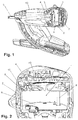
- the tacker off Fig. 1 is a hand-held device, comprising a housing 19 and a combustion chamber 1 with a partially cylindrical combustion chamber wall 2, which is rigidly connected to the housing 19. Adjacent to the combustion chamber 1 is a cylinder 3 with a drive piston 4 guided therein.
- a safety mechanism of the device comprises annensetzhülse 5, which is placed on a workpiece (not shown) and is pressed against the pressure of a spring. Only in this state, a driving operation can be triggered by igniting a blowing agent in the form of a fuel gas in the combustion chamber.
- a swirl plate 6 is also arranged, which can be moved by the combustion chamber 1 before ignition.
- a bottom 7 of the combustion chamber 1 is movable along an axis coincident with the driving direction, so that the volume of the combustion chamber is variable.
- the bottom 7 is sealed for this purpose with a circumferential seal 8 with respect to the cylindrical combustion chamber wall 2.
- the seal 8 is shown only schematically.
- An inventive detailed design of the seal 8 is in Fig. 3 shown in detail.
- the bottom is rigidly connected to the housing and the combustion chamber wall is formed as an axially movable sleeve.
- the combustion chamber wall is so far adjustable relative to the ground, so that forms an inlet and / or outlet opening of the combustion chamber for air and / or fuel between the bottom and the combustion chamber wall.
- the bottom 7 can be moved via an adjusting rod 9 in the direction of the axis, wherein the adjusting rod 9 passes through a passage in a front, second bottom of the combustion chamber.
- the impressions of the attachment sleeve 5 initially tensions a spring and acts on the adjustment rod 9, which in turn displaces the base 7.
- sufficient for an ignition volume of the combustion chamber is only opened.
- condensed water is regularly stripped off. To avoid binding of the mechanism, as little water as possible should penetrate into the region of the seal 8 and freeze.
- Fig. 3 shows the seal 8 in an exploded view.
- the seal 8 comprises a circumferentially extending, relative to a cylinder axis 20 of the combustion chamber wall, circular first sealing ring 21 with a first interruption 22 and with respect to the cylinder axis 20 also extending in the circumferential direction, circular second sealing ring 23 with a second interruption 24.
- the second sealing ring 23 in the direction of the cylinder axis 20 is flat against the first sealing ring 21, preferably over its entire circumference about the cylinder axis 20 circumference, the interruptions 22, 24 except.
- the first interruption 22 has a first angular position 25, while the second interruption 24 has a second angular position 26.
- the first angular position 25 and the second angular position 26 enclose an angle a of 45 °. This angle ⁇ is determined by a fixing device 27.
- the fixing device 27 comprises a projection, not shown, on the first sealing ring 21, which protrudes into a recess 28 on the second sealing ring and engages, and a projection 29 on the second sealing ring 23, which protrudes into a recess, not shown, on the first sealing ring 21 and engages, so that there is a positive connection between the sealing rings 21, 22 in the circumferential direction, that is, a relative movement between the sealing rings 21, 22 in the circumferential direction is prevented.
Landscapes
- Engineering & Computer Science (AREA)
- Chemical & Material Sciences (AREA)
- Combustion & Propulsion (AREA)
- Mechanical Engineering (AREA)
- Portable Nailing Machines And Staplers (AREA)
Priority Applications (6)
| Application Number | Priority Date | Filing Date | Title |
|---|---|---|---|
| EP16153619.8A EP3199301A1 (fr) | 2016-02-01 | 2016-02-01 | Chambre de combustion et appareil d'enfoncement |
| PCT/EP2017/051964 WO2017134021A1 (fr) | 2016-02-01 | 2017-01-31 | Chambre de combustion et outil d'enfoncement |
| US16/073,369 US20190047129A1 (en) | 2016-02-01 | 2017-01-31 | Combustion chamber and drive-in device |
| CN201780008591.9A CN108602178A (zh) | 2016-02-01 | 2017-01-31 | 燃烧室和驱入设备 |
| JP2018540126A JP2019505401A (ja) | 2016-02-01 | 2017-01-31 | 燃焼室及び打込み装置 |
| EP17702096.3A EP3411189B1 (fr) | 2016-02-01 | 2017-01-31 | Chambre de combustion et appareil d'enfoncement |
Applications Claiming Priority (1)
| Application Number | Priority Date | Filing Date | Title |
|---|---|---|---|
| EP16153619.8A EP3199301A1 (fr) | 2016-02-01 | 2016-02-01 | Chambre de combustion et appareil d'enfoncement |
Publications (1)
| Publication Number | Publication Date |
|---|---|
| EP3199301A1 true EP3199301A1 (fr) | 2017-08-02 |
Family
ID=55275010
Family Applications (2)
| Application Number | Title | Priority Date | Filing Date |
|---|---|---|---|
| EP16153619.8A Withdrawn EP3199301A1 (fr) | 2016-02-01 | 2016-02-01 | Chambre de combustion et appareil d'enfoncement |
| EP17702096.3A Active EP3411189B1 (fr) | 2016-02-01 | 2017-01-31 | Chambre de combustion et appareil d'enfoncement |
Family Applications After (1)
| Application Number | Title | Priority Date | Filing Date |
|---|---|---|---|
| EP17702096.3A Active EP3411189B1 (fr) | 2016-02-01 | 2017-01-31 | Chambre de combustion et appareil d'enfoncement |
Country Status (5)
| Country | Link |
|---|---|
| US (1) | US20190047129A1 (fr) |
| EP (2) | EP3199301A1 (fr) |
| JP (1) | JP2019505401A (fr) |
| CN (1) | CN108602178A (fr) |
| WO (1) | WO2017134021A1 (fr) |
Families Citing this family (1)
| Publication number | Priority date | Publication date | Assignee | Title |
|---|---|---|---|---|
| EP3034239A1 (fr) * | 2014-12-19 | 2016-06-22 | HILTI Aktiengesellschaft | Appareil d'enfoncement doté de chambre de combustion réglable |
Citations (7)
| Publication number | Priority date | Publication date | Assignee | Title |
|---|---|---|---|---|
| DE4032202A1 (de) * | 1990-10-11 | 1992-04-16 | Hilti Ag | Setzgeraet fuer befestigungselemente |
| US20010006044A1 (en) * | 1999-12-23 | 2001-07-05 | Roland Hasler | Portable internal combustion-engined tool and method of forming a gas mixture in the tool combustion chamber |
| EP1293302A2 (fr) * | 2001-08-30 | 2003-03-19 | Illinois Tool Works Inc. | Segment de piston autolubrifiant et non-étanch pour outil entraíné par gaz de combustion pour enfoncer des attaches |
| DE10226878A1 (de) | 2002-06-17 | 2003-12-24 | Hilti Ag | Gasbetriebenes Setzgerät |
| US20050279802A1 (en) * | 2004-06-14 | 2005-12-22 | Moeller Larry M | Seal for portable fastener driving tool |
| EP2465643A2 (fr) * | 2010-12-15 | 2012-06-20 | HILTI Aktiengesellschaft | Appareil de fixation de boulons et procédé de fonctionnement d'un appareil de fixation de boulons |
| EP2666979A2 (fr) * | 2012-05-25 | 2013-11-27 | Aisin Seiki Kabushiki Kaisha | Appareil de commande de synchronisation de soupape |
Family Cites Families (22)
| Publication number | Priority date | Publication date | Assignee | Title |
|---|---|---|---|---|
| US1777325A (en) * | 1928-03-19 | 1930-10-07 | Electric Boat Co | Piston ring and piston construction |
| US1782427A (en) * | 1928-09-04 | 1930-11-25 | Charles E Johnson | Piston ring |
| US2183199A (en) * | 1937-10-09 | 1939-12-12 | Vergil M Lutz | Piston ring |
| US2231801A (en) * | 1938-02-21 | 1941-02-11 | Cords William | Packing ring element and assembly |
| US2203208A (en) * | 1938-10-28 | 1940-06-04 | Simplex Products Corp | Piston sealing device |
| US3364547A (en) * | 1964-06-04 | 1968-01-23 | Ramsey Corp | Method of coating piston ring segments |
| US3346264A (en) * | 1965-01-18 | 1967-10-10 | Muskegon Piston Ring Co Inc | Oil rings |
| JPS5639841U (fr) * | 1979-09-06 | 1981-04-14 | ||
| JPS5798356U (fr) * | 1980-12-09 | 1982-06-17 | ||
| DE19950351C2 (de) * | 1999-10-19 | 2002-06-13 | Hilti Ag | Vorrichtung zur Erzeugung einer laminaren Flammfront, insbesondere für brennkraftbetriebene Setzgeräte zum Setzen von Befestigungselementen |
| DE10032310C2 (de) * | 2000-07-04 | 2003-07-17 | Hilti Ag | Tragbares, brennkraftbetriebenes Arbeitsgerät, insbesondere Setzgerät für Befestigungselemente, und Verfahren zu seiner Betriebssteuerung |
| JP4135069B2 (ja) * | 2002-08-09 | 2008-08-20 | 日立工機株式会社 | 燃焼式打込み工具 |
| DE10311155A1 (de) * | 2003-03-14 | 2004-09-23 | Gapi Technische Produkte Gmbh | Dichtring und Dichtringanordnung |
| FR2858261B1 (fr) * | 2003-07-29 | 2005-09-09 | Prospection & Inventions | Appareil a fonctionnement a gaz d'entrainement d'un element par piston |
| CN2721888Y (zh) * | 2004-09-03 | 2005-08-31 | 褚新社 | 一种活塞及密封环 |
| DE102005000077A1 (de) * | 2005-06-16 | 2006-12-21 | Hilti Ag | Elektrisch betriebenes Eintreibgerät |
| US7461583B2 (en) * | 2006-07-21 | 2008-12-09 | Mahle Engine Components Usa, Inc. | Variable tension ring mechanism |
| JP2010031835A (ja) * | 2008-06-23 | 2010-02-12 | Nissan Motor Co Ltd | 内燃機関用オイルリング及びピストン |
| TWM363973U (en) * | 2009-04-28 | 2009-09-01 | Chung-Yi Lee | Fired pin assembly for powder actuated nail gun |
| AT508131B1 (de) * | 2009-12-14 | 2010-11-15 | Hoerbiger Kompressortech Hold | Kolben mit kolbenringen und stützringen |
| CN102889383A (zh) * | 2012-09-14 | 2013-01-23 | 常州市奥琳斯邦热能设备有限公司 | 快开门式压力容器活动密封装置 |
| FR2996897B1 (fr) * | 2012-10-15 | 2015-05-01 | Montabert Roger | Dispositif d’etancheite pour appareil hydraulique a percussions, et appareil hydraulique a percussions comprenant un tel dispositif d’etancheite |
-
2016
- 2016-02-01 EP EP16153619.8A patent/EP3199301A1/fr not_active Withdrawn
-
2017
- 2017-01-31 WO PCT/EP2017/051964 patent/WO2017134021A1/fr not_active Ceased
- 2017-01-31 EP EP17702096.3A patent/EP3411189B1/fr active Active
- 2017-01-31 US US16/073,369 patent/US20190047129A1/en not_active Abandoned
- 2017-01-31 JP JP2018540126A patent/JP2019505401A/ja active Pending
- 2017-01-31 CN CN201780008591.9A patent/CN108602178A/zh active Pending
Patent Citations (7)
| Publication number | Priority date | Publication date | Assignee | Title |
|---|---|---|---|---|
| DE4032202A1 (de) * | 1990-10-11 | 1992-04-16 | Hilti Ag | Setzgeraet fuer befestigungselemente |
| US20010006044A1 (en) * | 1999-12-23 | 2001-07-05 | Roland Hasler | Portable internal combustion-engined tool and method of forming a gas mixture in the tool combustion chamber |
| EP1293302A2 (fr) * | 2001-08-30 | 2003-03-19 | Illinois Tool Works Inc. | Segment de piston autolubrifiant et non-étanch pour outil entraíné par gaz de combustion pour enfoncer des attaches |
| DE10226878A1 (de) | 2002-06-17 | 2003-12-24 | Hilti Ag | Gasbetriebenes Setzgerät |
| US20050279802A1 (en) * | 2004-06-14 | 2005-12-22 | Moeller Larry M | Seal for portable fastener driving tool |
| EP2465643A2 (fr) * | 2010-12-15 | 2012-06-20 | HILTI Aktiengesellschaft | Appareil de fixation de boulons et procédé de fonctionnement d'un appareil de fixation de boulons |
| EP2666979A2 (fr) * | 2012-05-25 | 2013-11-27 | Aisin Seiki Kabushiki Kaisha | Appareil de commande de synchronisation de soupape |
Also Published As
| Publication number | Publication date |
|---|---|
| CN108602178A (zh) | 2018-09-28 |
| EP3411189A1 (fr) | 2018-12-12 |
| US20190047129A1 (en) | 2019-02-14 |
| JP2019505401A (ja) | 2019-02-28 |
| WO2017134021A1 (fr) | 2017-08-10 |
| EP3411189B1 (fr) | 2020-04-22 |
Similar Documents
| Publication | Publication Date | Title |
|---|---|---|
| DE1961079C2 (de) | Vorrichtung zur Steuerung einer hydraulischen Fernbedienungseinheit | |
| DE102011013139A1 (de) | Kolben für einen Verbrennungsmotor | |
| WO2017108782A1 (fr) | Outil de pose actionné par la pression d'une combustion et procédé pour faire fonctionner un outil de pose de ce type | |
| DE102018131097A1 (de) | Vorrichtung zur Sicherung eines Druckausgleichsventils in einem Getriebebauteil, Druckausgleichsventil und Vorrichtung zur Regelung von Drücken eines Strömungsmittels in einem Fahrzeuggetriebe | |
| DE3034257A1 (de) | Pyrotechnische antriebseinrichtung insbesondere fuer eine rueckstrammvorrichtung eines sicherheitsgurtsystems | |
| EP0656522A1 (fr) | Douille pour cartouche | |
| EP3233381B1 (fr) | Appareil d'enfoncement doté de chambre de combustion réglable | |
| DE2706884A1 (de) | Pneumatische feder | |
| DE102005000113B4 (de) | Setzgerät | |
| EP3411189B1 (fr) | Chambre de combustion et appareil d'enfoncement | |
| EP1837111B1 (fr) | Installation d'ébarbage thermique dotée d'une ventilation rapide | |
| DE19810985C2 (de) | Verfahren und Vorrichtung für die automatisierte Montage von Konus-Halbklemmbacken eines Ventils einer Verbrennungskraftmaschine | |
| DE102011106514B4 (de) | Pyrotechnischer Aktuator mit Entlüftung, Motorhaubenaufsteller und Gurtstraffer mit einem solchen Aktuator | |
| EP2949975A1 (fr) | Vanne guillotine destinée à interrompre un flux de fluide dans une conduite | |
| DE102005000106B4 (de) | Setzgerät | |
| EP1688694B1 (fr) | Système mécanique d'initiation pour munitions sans douille | |
| EP1386106A1 (fr) | Dispositif de connexion | |
| DE102006021170A1 (de) | Sicherheitsventil | |
| DE69227683T2 (de) | Pneumatisches Befestigungsmitteleintreibgerät mit verbessertem Ventil | |
| DE1428628C (de) | Elastische Dichtung fur Druckluft Schußwaffen | |
| DE2614900C3 (de) | Druckbegrenzungsventil für flüssige Arbeitsmedien | |
| DE102004032240A1 (de) | Spielausgleichselement | |
| EP0343339A2 (fr) | Dispositif de blocage | |
| DE102014213720A1 (de) | Elektromagnetisch betätigbares Saugventil | |
| DE3704129A1 (de) | Wegeventil |
Legal Events
| Date | Code | Title | Description |
|---|---|---|---|
| PUAI | Public reference made under article 153(3) epc to a published international application that has entered the european phase |
Free format text: ORIGINAL CODE: 0009012 |
|
| AK | Designated contracting states |
Kind code of ref document: A1 Designated state(s): AL AT BE BG CH CY CZ DE DK EE ES FI FR GB GR HR HU IE IS IT LI LT LU LV MC MK MT NL NO PL PT RO RS SE SI SK SM TR |
|
| AX | Request for extension of the european patent |
Extension state: BA ME |
|
| STAA | Information on the status of an ep patent application or granted ep patent |
Free format text: STATUS: THE APPLICATION IS DEEMED TO BE WITHDRAWN |
|
| 18D | Application deemed to be withdrawn |
Effective date: 20180203 |