EP3199410B1 - Procédé de commande pour un rétracteur de ceinture de sécurité électrique et rétracteur de ceinture de sécurité électrique - Google Patents
Procédé de commande pour un rétracteur de ceinture de sécurité électrique et rétracteur de ceinture de sécurité électrique Download PDFInfo
- Publication number
- EP3199410B1 EP3199410B1 EP16153300.5A EP16153300A EP3199410B1 EP 3199410 B1 EP3199410 B1 EP 3199410B1 EP 16153300 A EP16153300 A EP 16153300A EP 3199410 B1 EP3199410 B1 EP 3199410B1
- Authority
- EP
- European Patent Office
- Prior art keywords
- spindle
- seatbelt
- pull
- rotor
- retractor
- Prior art date
- Legal status (The legal status is an assumption and is not a legal conclusion. Google has not performed a legal analysis and makes no representation as to the accuracy of the status listed.)
- Active
Links
Images





Classifications
-
- B—PERFORMING OPERATIONS; TRANSPORTING
- B60—VEHICLES IN GENERAL
- B60R—VEHICLES, VEHICLE FITTINGS, OR VEHICLE PARTS, NOT OTHERWISE PROVIDED FOR
- B60R22/00—Safety belts or body harnesses in vehicles
- B60R22/48—Control systems, alarms, or interlock systems, for the correct application of the belt or harness
-
- B—PERFORMING OPERATIONS; TRANSPORTING
- B60—VEHICLES IN GENERAL
- B60R—VEHICLES, VEHICLE FITTINGS, OR VEHICLE PARTS, NOT OTHERWISE PROVIDED FOR
- B60R22/00—Safety belts or body harnesses in vehicles
- B60R22/34—Belt retractors, e.g. reels
- B60R22/44—Belt retractors, e.g. reels with means for reducing belt tension during use under normal conditions
-
- B—PERFORMING OPERATIONS; TRANSPORTING
- B60—VEHICLES IN GENERAL
- B60R—VEHICLES, VEHICLE FITTINGS, OR VEHICLE PARTS, NOT OTHERWISE PROVIDED FOR
- B60R22/00—Safety belts or body harnesses in vehicles
- B60R22/34—Belt retractors, e.g. reels
- B60R22/46—Reels with means to tension the belt in an emergency by forced winding up
-
- H—ELECTRICITY
- H02—GENERATION; CONVERSION OR DISTRIBUTION OF ELECTRIC POWER
- H02K—DYNAMO-ELECTRIC MACHINES
- H02K11/00—Structural association of dynamo-electric machines with electric components or with devices for shielding, monitoring or protection
- H02K11/20—Structural association of dynamo-electric machines with electric components or with devices for shielding, monitoring or protection for measuring, monitoring, testing, protecting or switching
- H02K11/21—Devices for sensing speed or position, or actuated thereby
- H02K11/215—Magnetic effect devices, e.g. Hall-effect or magneto-resistive elements
-
- H—ELECTRICITY
- H02—GENERATION; CONVERSION OR DISTRIBUTION OF ELECTRIC POWER
- H02K—DYNAMO-ELECTRIC MACHINES
- H02K7/00—Arrangements for handling mechanical energy structurally associated with dynamo-electric machines, e.g. structural association with mechanical driving motors or auxiliary dynamo-electric machines
- H02K7/14—Structural association with mechanical loads, e.g. with hand-held machine tools or fans
-
- B—PERFORMING OPERATIONS; TRANSPORTING
- B60—VEHICLES IN GENERAL
- B60R—VEHICLES, VEHICLE FITTINGS, OR VEHICLE PARTS, NOT OTHERWISE PROVIDED FOR
- B60R22/00—Safety belts or body harnesses in vehicles
- B60R22/34—Belt retractors, e.g. reels
- B60R22/44—Belt retractors, e.g. reels with means for reducing belt tension during use under normal conditions
- B60R2022/4473—Belt retractors, e.g. reels with means for reducing belt tension during use under normal conditions using an electric retraction device
-
- B—PERFORMING OPERATIONS; TRANSPORTING
- B60—VEHICLES IN GENERAL
- B60R—VEHICLES, VEHICLE FITTINGS, OR VEHICLE PARTS, NOT OTHERWISE PROVIDED FOR
- B60R22/00—Safety belts or body harnesses in vehicles
- B60R22/34—Belt retractors, e.g. reels
- B60R22/46—Reels with means to tension the belt in an emergency by forced winding up
- B60R2022/4666—Reels with means to tension the belt in an emergency by forced winding up characterised by electric actuators
-
- B—PERFORMING OPERATIONS; TRANSPORTING
- B60—VEHICLES IN GENERAL
- B60R—VEHICLES, VEHICLE FITTINGS, OR VEHICLE PARTS, NOT OTHERWISE PROVIDED FOR
- B60R22/00—Safety belts or body harnesses in vehicles
- B60R22/48—Control systems, alarms, or interlock systems, for the correct application of the belt or harness
- B60R2022/4808—Sensing means arrangements therefor
- B60R2022/4825—Sensing means arrangements therefor for sensing amount of belt winded on retractor
Definitions
- the invention relates to a control method for an electric seatbelt retractor comprising the features of the preamble of claim 1 and to an electric seatbelt retractor comprising the features of the preamble of claim 7.
- Seatbelt systems in vehicles comprise a seatbelt retractor, a vehicle-fixed buckle and a seatbelt with a slidable tongue which may be locked in the buckle.
- the seatbelt retractor comprises a spindle onto which the seatbelt is wound up and which may rotate in a frame in pull-in as well as in pull-out direction of the seatbelt.
- the retractor is further provided with a blocking device for blocking the spindle in the pull-out direction when a predetermined value of the seatbelt pull-out speed or a predetermined value of the vehicle deceleration is exceeded.
- the blocking device is triggered by a mechanical seatbelt acceleration sensor and by a mechanical vehicle deceleration sensor.
- the seatbelt retractor with irreversible and reversible pretensioning devices, which pull out a possible slack out of the seatbelt in a precrash situation or in an early phase of the crash to couple the occupant closer to the vehicle deceleration.
- the reversible pretensioner is realized in modern seatbelt systems by an electric motor, which may be coupled with the spindle by a clutch.
- the clutch is closed for example by friction or inertia forces when the electric motor is activated.
- the electric motor increases the price of the seatbelt retractor significantly, it is intended to use the electric motor for as many functions as possible, for example also to support the retracting movement into the parking position or to reduce the retracting force for comfort reasons or the like.
- the seatbelt retractor needs to be provided with a sensor device which provides a signal for controlling the electric motor.
- the sensor devices in existing seatbelt re-tractors are realized by magnetic wheels with a plurality of magnet poles with different polarization, which are fixed at the spindle.
- the magnet poles comprise identical dimensions and are arranged at the circumference of the magnetic wheel in a regular arrangement.
- the sensor devices comprise a sensor, for example a hall sensor, which is positioned face to the magnet poles of the magnetic wheel at a frame of the retractor.
- the sensor device detects the rotational movement of the spindle, wherein the detected rotational angle or the detected revolutions are used to trigger the electric motor, wherein the signal may be further processed in a CPU.
- the rotational movement or the rotational position of the spindle is used here also as a representative signal for the seatbelt pull-out length, which is the essential criterion for the activation of the electric motor for extraction and retraction of the seatbelt.
- a seatbelt retractor having an electric motor for reversable pretensioning as well as for an improvement of the comfort during normal use.
- the electric motor may drive the spindle in pull-in direction during pretensioning and may also adjust the spring force of a return spring for comfort reason during normal use.
- the spring is tensioned by a first relative movement of the spindle to the rotor in a first direction, and the tensioned spring drives the spindle subsequently to a second relative movement in a second direction, which is oriented opposite to the first direction, wherein the sensor device generates a signal when detecting the second movement of the spindle, by which the electric motor is activated to drive the spindle in the second direction.
- the spring is tensioned by a relative movement like for example the extraction of the seatbelt, and that the relative movement is performed in a second step when the spring is expanding afterwards and drives thereby the spindle in the opposite direction.
- the spring is acting in this case as an energy storage which is loaded during the movement of the spindle before.
- the energy in the spring is used afterwards to drive the spindle for preferred 5 to 20 degrees to the rotor in the opposite direction for generating a signal by the sensor device.
- This short movement of the spindle which is initiated by the tensioned spring is detected then by the sensor device to trigger the electric motor which drives the spindle further in the same direction.
- the electric motor is activated preferably in pull-out direction of the seatbelt when the sensor device detects a relative movement of the spindle in pull-out direction to the rotor when the seatbelt is pulled out from a parking position.
- the spring is expanded in a neutral position.
- the spindle turns versus the non-rotating rotor with tensioning the spring, so it performs a relative movement in pull-out direction with respect to the rotor. This relative movement of the spindle to the rotor is detected by the sensor device which triggers then the electric motor to drive the rotor and the spindle further in pull-out direction.
- the electric motor is activated in pull-in direction of the seatbelt after buckling up of the seatbelt.
- the seatbelt is pulled in to remove possible slack out of the seatbelt so that the seatbelt is abutting afterwards as close as possible at the occupant.
- the electric motor acts in this case as a reversible pretensioner, which tensions the seatbelt each time after buckling up.
- the electric motor is activated preferably in pull-in direction of the seatbelt when the sensor device detects a relative movement of the spindle in pull-in direction to the rotor after unbuckling the seatbelt from a vehicle-fixed buckle.
- the electric motor is used in this case for retracting the seatbelt into the parking position after unbuckling and after the relative movement of the spindle has been detected.
- the spring is tensioned to load the spindle in pull-in direction before releasing the seatbelt from the vehicle-fixed buckle against the pull-in direction of the seatbelt, and the spring drives the spindle after releasing the seatbelt in pull-in direction, and the electric motor is activated by a signal of the sensors detecting the rotation of the spindle in pull-in direction to drive the spindle in pull-in direction.
- This relative movement of the spindle versus the rotor or versus the retractor-fixed part may be used afterwards to provide a signal in the sensor device for triggering the electric motor to drive the spindle subsequently further to retract the seatbelt into the final parking position.
- the seatbelt After buckling up of the seatbelt, the seatbelt is pulled-in for a maximum of length as close as possible to the torso of the occupant.
- the tensioning of the spring may then also be performed by short movements of the occupant in a forward direction during the normal use for example by operating the radio, active movements when driving or when reaching the glove compartment or the like.
- the spring is tensioned when the seatbelt is locked in the buckle with respect to the rotor or with respect to the retractor-fixed part in pull-in direction.
- this movement is used to tension the spring and to load the spindle in pull-in direction.
- the spindle is automatically rotated in pull-in direction by the tensioned spring. This movement can then be used to generate the signal and to trigger the electric motor to retract the seatbelt.
- the spindle comprises an abutment for the rotor which limits the relative movement of the spindle to the rotor.
- the abutment may be used for example to transmit the driving movement directly from the rotor to the spindle.
- the abutment may be also so used to realize a webbing sensitive blocking when the seatbelt pull-out acceleration exceeds a predetermined value. The electric motor is blocked or deactivated in this case, so that the spindle is blocked by the abutment which is abutting at the blocked rotor.
- the sensor device comprises a sensor and a magnetic wheel, wherein the sensor is fixed at a frame of the retractor, and the magnetic wheel is fixed at the spindle.
- the advantage of the solution is a very easy and reliable attachment of the sensor.
- the sensor detects in this case the relative movement of the spindle versus the frame which is here the retractor-fixed part.
- the electric motor and the rotor do not perform any movement when the electric motor is not activated, the movement of the spindle with respect to the rotor is identical to the movement of the spindle with respect to the frame and any other retractor-fixed part.
- the magnetic wheel is attached to the spindle and is used to create the signal in the sensor when rotating together with the spindle.
- the magnetic wheel is provided preferably with a plurality of single magnets having different polarities, which are arranged at a common diameter with alternating poles.
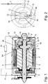
- the electric seatbelt retractor comprising a U-shaped frame with two opposing journals 6 and 7 for fixing the retractor at a vehicle structure, a spindle 2 onto which a seatbelt 1 is wound up and an electric motor 4 which is coupled directly or can be coupled via a clutch with the spindle 2.
- the spindle 2 comprises a central through hole in which a rotor 3 is arranged.
- a drive wheel 5 is fixed at the rotor 3, which engages with another gear wheel of a not shown gear mechanism arranged between the spindie 2 and the electric motor 4.
- the gear mechanism transmits the rotational movement of the electric motor 4 via the drive wheel 5 to the rotor 3.
- the rotor 3 further comprises at its other end a radial flange 14 with an axial directed recess 18 at an outer section and a central pin 19 extending at the end. Furthermore, a cup 8 is provided which is fixed to the spindle 2. Therefore, the cup 8 can be also understood as a part of the spindle 2. In an outer section of the cup 8, it is provided a recess 17, which is realized by an axial through hole.
- a spring 11 is arranged which comprises a coil section surrounding the pin 19 and two ends 12 and 13 extending in two opposing axial directions to the outside from the coil section.
- the spring 11 is kept in position by the pin 19 and engages with its first end 12 into the recess 18 of the flange 14 of the rotor 3 and with its other end 13 into the recess 17 of the cup 8. Therefore, the spring 11 is fixed in circumferential direction with the first end 12 with the rotor 3 and with the second end 13 with the cup 8 and the spindle 2.
- the spring 11 comprises several coils in the coil section with which the spring 11 embraces the pin 19.
- the ends 12 and 13 of the spring 11 are formed as radial arms which are bent at their ends in axial directions extending to the outside, away from the coil section.
- the coils of the coil section are tensioned or expanded depending on the status of the spring 11 and the direction of the rotation of the relative movement.
- the spring 11 enables a relative movement of the spindle 2 to the rotor 3 with tensioning or expanding the spring 11.
- a magnetic wheel 9 is provided, which is also shown in Figure 18 from the front side.
- the magnetic wheel 9 comprises a plurality of magnet poles 25 and is fixed at the cup 8, so that the magnetic wheel 9 is also fixed versus the spindle 2.
- the magnet poles 25 are designed with identical dimensions in a ring-shaped arrangement at the outer circumference of the magnetic wheel 9 on a common diameter.
- the magnetic wheel 9 is arranged concentric to the axis of the spindle 2, so that the magnet poles 25 are also arranged concentric to the axis of the spindle 2.
- the magnet poles 25 are arranged with alternating south and north poles, which create an alternating magnetic field in axial direction to the outside of the cup 8.
- the cup 8 and the end of the spindle 2 extending through the right journal 7 of the frame are encapsulated by a cup-shaped housing 16 which is attached at the journal 7 of the frame.
- a sensor device 10 with for example two sensors 23 and 24 like hall sensors, which are positioned face to the magnet poles 25 of the magnetic wheel 9.
- the sensors 23 and 24 are positioned with a defined distance to each other in circumferential direction which enables a detection of the direction in which the spindle 2 turns versus the housing 16 and the frame by detecting an offset of the signals S1 and S2 generated by the sensors 23 and 24 like shown in the right illustration of Figure 18 .
- the created tension force is used afterwards in a following situation to initiate a second relative movement of the spindle 2 versus the rotor 3 which is detected by the sensor device 10.
- the sensor device 10 creates thereby a signal which depends on the direction of the relative movement and which is used to control the electric motor 4 and to activate the electric motor 4 to drive the spindle 2 further in the same direction.
- the retractor is shown in a view to the front side at the rotor 3 and the spindle 2, wherein the housing 16 and the frame of the retractor have been deleted to facilitate the illustration.
- the spring 11 is arranged with the coil section embracing the central pin 19 of the rotor 3.
- the first end 12 is connected with the flange 14 of the rotor 3 and the second end 13 is connected with the cup 8 in circumferential direction, wherein the cup 8 is also fixed to the spindle 2, so that the second end 13 is also fixed in circumferential direction to the spindle 2.
- the sensor device 10 generates a signal depending on the direction of the relative rotation of the spindle 2 versus the rotor 3. As the rotor 3 is not moving before the activation of the electric motor 4, the relative rotation of the spindle 2 versus the rotor 3 is identical with the relative rotation of the spindle 2 versus the frame and the housing 16 of the retractor and versus every other retractor-fixed part. As the sensor device 10 is fixed at the housing 16, the relative rotation or movement of the spindle 2 versus the rotor 3 can be detected by the sensor device 10 fixed at the housing 16 of the detector. The sensor device 10 is connected via a signal line with a central processing unit 15 which is also connected with a signal line with the electric motor 4.
- the arrangement of the sensor device 10 at the housing 16 facilitates the design structure and the connection of the sensor device 10 with the central processing unit 15 significantly, because the sensor device 10 is fixed at a non-moving part.
- the sensor device 10 may also be fixed at the spindle 2 or at the rotor 3 to detect the relative movement between both parts, wherein in this case the signal needs to be transmitted via a moving contact like for example a collector ring.
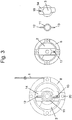
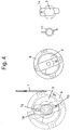
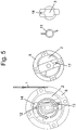
- the control method is explained by the Figures 3 to 17 .
- the rotor 3 is arranged in a position starting from an upright position, where the flange 14 is arranged together with the first end 12 of the spring 11 in the 12 o'clock position to facilitate the understanding of the movements.
- the spindle 2 with the cup 8 there are shown the spindle 2 with the cup 8
- the rotor 3 with the flange 14 and the spring 11 arranged between them In the right illustration, there are shown the spindle 2, the rotor 3 and the spring 11 as single parts in the relevant orientations.
- the electric retractor with the spindle 2 and the rotor 3 is shown in a position in which the seatbelt 1 is wound up completely onto the spindle 2. This position is designated also as the parking position.
- the spring 11 is relaxed and both ends 12 and 13 of the spring 11 are arranged opposite to each other with an angle of 180 degrees between them.
- the spindle 2 rotates versus the rotor 3 and also versus the housing 16 and the sensor device 10 fixed thereon.
- the housing 16 is attached at the frame of the retractor and is therefore in this case a retractor-fixed part.
- the movement of the spindle 2 is a first relative movement on which the spring 11 is tensioned and which generates two different signals S1 and S2 in the sensors 23 and 24 with an offset to each other, wherein the offset of the signals S1 and S2 depends on the direction of the rotation of the spindle 2.
- the spindle 2 rotates in counter clockwise direction, so that the sensor 23 generates the signal S1 and the sensor 24 generates the time-delayed signal S2.
- the signals S1 and S2 are processed in the central processing unit 15 which generates another signal to control the electric motor 4 which is activated to drive the spindle 2 further in counter clockwise direction like shown in Figure 5 by the circular arrow in the left illustration.
- the rotor 3 and the first end 12 of the spring 11 are driven then together by the electric motor 4 in counter clockwise direction to follow the pull-out movement of the spindle 2.
- the orientation of both parts to each other is not changed and the spring 11 is kept in the tensioned status. This orientation is kept until the occupant stops the pull-out movement and locks the tongue of the seatbelt 1 in a vehicle-fixed buckle which is not shown.
- the sequence of the signals S1 and S2 is reversed in comparison to the illustration in Figure 18 .
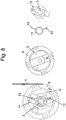
- the signals S1 and S2 are processed in the central processing unit 15 to trigger the electric motor 4 to drive the spindle 2 in clockwise direction to pull-in possible slack out of the seatbelt until the seatbelt 1 is in contact with the chest of the occupant like in Figure 6 .
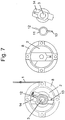
- the spindle 2 When the slack is pulled out of the seatbelt 1, the spindle 2 is driven in pull-in direction, wherein the movement of the spindle 2 is retarded at the end of the movement until the spindle 2 is blocked. As soon as the spindle 2 is blocked, the electric motor 4 and the rotor 3 perform a further rotation versus the blocked spindle 2, which is shown by the arrow in Figure 7 .
- This first relative movement of the rotor 3 versus the spindle 2 tensions the spring 11.
- the orientation of the spindle 2, the rotor 3 and the spring 11 is kept when the occupant does not perform any further movement afterwards.
- the spindle 2 is therefore preloaded in pull-in direction, so that the seatbelt 1 is abutting with a slightly higher restraining force resulting from the tension of the spring 11.
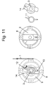
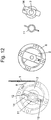
- the spring 11 expands and drives the spindle 2 in the second direction in pull-in direction like shown in Figure 12 .
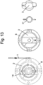
- This relative movement of the spindle 2 versus the rotor 3 and versus the housing 16 is detected by the sensor device 10 and the electric motor 4 is triggered again to drive the rotor 3 in the second direction, in this case the second direction is the pull-in direction like shown in the Figure 13 .
- the movement of the rotor 3 is transmitted in this case again via the spring 11 to the spindle 2 which is driven therefore also in pull-in direction of the seatbelt 1.
- the seatbelt 1 is retracted then until the parking position is reached.
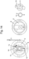
- the spindle 2 is retarded and finally stopped when reaching the parking position, while the electric motor 4 drives the rotor 3 further to preload the spring and holding the preloading for a predetermined time like shown in Figure 14 .
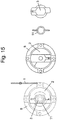
- the electric motor 4 is activated again to drive the rotor 3 in the other direction until the parking position from Figure 15 is reached.
- the last step is necessary to distinguish the pull-in movement of the seatbelt 1 into the parking position from the pull-in movement when the occupant returns to the seated position after leaning forward.
- the electric motor 4 is triggered upon a signal which is generated when the spindle 2 performs a relative movement to the housing 16 and the sensor device 10 attached thereto. As the rotor 3 is standing before the activation of the electric motor 4, this relative movement is identical with the relative movement between the spindle 2 and the rotor 3. The electric motor 4 is activated to drive the rotor 3 then in the same direction like the spindle 2 moving before.
- the relative movement of the spindle 2 which is detected by the sensor device 10 is generated either by the occupant itself, when he pulls the seatbelt 1 like for example from the parking position or to turn on the music.
- the relative movement of the spindle 2 can also be initiated by the spring 11 when the spring 11 is tensioned in a foregoing step and expands afterwards to drive the spindle 2 preferably in pull-in direction.
- the relative movement is enabled by the spring 11 arranged between the spindle 2 and the rotor 3.
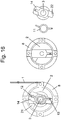
- the webbing sensitive blocking of the spindle 2 is also realized by using the spring 11 like described with the Figures 16 and 17 .
- the rotor 3 comprises at the opposite side to the flange 14 a radial outwardly directed finger 22.
- the spindle 2 is provided with a protrusion 21 at the axial front side which is directed in the left illustration of Figure 16 towards the observer.
- FIG 16 it is shown the orientation of the spindle 2 and the rotor 3 during the normal use, when the seatbelt 1 is applied, like in Figure 7 .
- the spindle 2 rotates in counter clockwise direction in the illustration until the protrusion 21 abuts at the finger 22 and stops therefore the further rotation of the spindle 2.
- the rotor 3 is blocked in this case via the deactivated electric motor 4, also the spindle 2 is blocked against further rotation in pull-out direction by the protrusion 21 which is abutting at the finger 22.
Landscapes
- Engineering & Computer Science (AREA)
- Mechanical Engineering (AREA)
- Power Engineering (AREA)
- Automation & Control Theory (AREA)
- Microelectronics & Electronic Packaging (AREA)
- Automotive Seat Belt Assembly (AREA)
Claims (14)
- Procédé de commande pour rétracteur de ceinture de sécurité électrique, le rétracteur comprenant :- un axe (2) et une ceinture de sécurité (1) enroulée sur celui-ci,- un moteur électrique (4) entraînant l'axe (2) par l'intermédiaire d'un rotor (3) dans un sens d'enroulement ou de déroulage lorsqu'il est activé, et- un dispositif capteur (11) détectant le mouvement de l'axe (2) ;- un ressort (11) étant prévu en étant agencé entre l'axe (2) et le rotor (3) pour permettre un mouvement relatif de l'axe (2) par rapport au rotor (3) ou par rapport à une partie fixe du rétracteur ; dans lequel procédé- le moteur électrique (4) est commandé par un signal du dispositif capteur (10) produit par le mouvement relatif de l'axe (2) par rapport au rotor (3) ou à une partie fixe du rétracteur sous l'effet de la contraction ou de l'allongement du ressort (11) ;- le ressort (11) étant contracté par un premier mouvement relatif de l'axe (2) par rapport au rotor (3) ou à la partie fixe du rétracteur dans un premier sens, et- le ressort contracté (11) entraînant l'axe (2) à la suite d'un deuxième mouvement relatif dans un deuxième sens, contraire au premier sens ;caractérisé en ce que- le dispositif capteur (10) produit un signal lors de la détection du deuxième mouvement de l'axe (2), au moyen duquel le moteur électrique (4) est activé pour entraîner l'axe (2) dans le deuxième sens.
- Procédé de commande selon la revendication 1, caractérisé en ce que- le ressort contracté (11) entraîne l'axe (2) sur 5 à 20 degrés dans le deuxième mouvement relatif pour provoquer la production d'un signal par le dispositif capteur (10).
- Procédé de commande selon l'une des revendications 1 et 2, caractérisé en ce que- le moteur électrique (4) est activé dans le sens de déroulage de la ceinture de sécurité (1) lorsque le dispositif capteur (10) détecte un mouvement relatif de l'axe (2) dans le sens de déroulage par rapport au rotor (3) ou à une partie fixe du rétracteur lorsque la ceinture de sécurité (1) est déroulée hors d'une position de repos.
- Procédé de commande selon la revendication 3, caractérisé en ce que- le moteur électrique (4) est activé dans le sens d'enroulement de la ceinture de sécurité (1) une fois que la ceinture de sécurité (1) a été bouclée.
- Procédé de commande selon l'une quelconque des revendications précédentes, caractérisé en ce que- le moteur électrique (4) est activé dans le sens d'enroulement de la ceinture de sécurité (1) lorsque le dispositif capteur (10) détecte un mouvement relatif de l'axe (2) dans le sens d'enroulement par rapport au rotor (3) ou à une partie fixe du rétracteur une fois que la ceinture de sécurité (1) a été détachée d'une boucle fixée au véhicule.
- Procédé de commande selon l'une des revendications 1 à 5, caractérisé en ce que- le ressort (11) est contracté avant que la ceinture de sécurité (1) ne soit dégagée de la boucle fixée au véhicule contre le sens d'enroulement de la ceinture de sécurité (1), et- le ressort contracté (11) entraîne l'axe (2) après que la ceinture de sécurité (1) a été dégagée de la boucle dans le sens d'enroulement, et- le moteur électrique (4) est activé par un signal du dispositif capteur (10) ayant détecté la rotation de l'axe (2) par rapport au rotor (3) ou à une partie fixe du rétracteur dans le sens d'enroulement pour entraîner l'axe (2) dans le sens d'enroulement.
- Rétracteur de ceinture de sécurité électrique comprenant :- un axe (2) et une ceinture de sécurité (1) enroulée sur celui-ci,- un moteur électrique (4) entraînant l'axe (2) par l'intermédiaire d'un rotor (3) dans un sens d'enroulement ou de déroulage lorsqu'il est activé, et- un dispositif capteur (10) détectant le mouvement de l'axe (2) ;- un ressort (11) étant prévu en étant agencé entre l'axe (2) et le rotor (3) pour permettre un mouvement relatif de l'axe (2) par rapport au rotor (3) ou à une partie fixe du rétracteur, et- l'axe (2) comprenant une butée pour le rotor (3) qui limite le mouvement relatif de l'axe (2) par rapport au rotor (3) ; caractérisé en ce que- le ressort (11) est contracté par un premier mouvement relatif de l'axe (2) par rapport au rotor (3) ou à la partie fixe du rétracteur dans un premier sens, et- le ressort contracté (11) entraîne l'axe (2) à la suite d'un deuxième mouvement relatif dans un deuxième sens ;- le dispositif capteur (10) produisant un signal lors de la détection du deuxième mouvement de l'axe (2), au moyen duquel le moteur électrique (4) est activé pour entraîner l'axe (2) dans le deuxième sens.
- Rétracteur de ceinture de sécurité électrique selon la revendication 7, caractérisé en ce que- le dispositif capteur (10) comprend un capteur et une roue magnétique (9) ;- le capteur étant fixe par rapport à un bâti du rétracteur, et- la roue magnétique (9) étant fixe par rapport à l'axe (2).
- Rétracteur de ceinture de sécurité électrique selon la revendication 8, caractérisé en ce que- la roue magnétique (9) est pourvue d'une pluralité d'aimants individuels (25) présentant des polarités différentes, lesquels sont agencés sur un diamètre commun, avec des pôles en alternance dans le sens circonférentiel.
- Rétracteur de ceinture de sécurité électrique selon l'une des revendications 7 à 9, caractérisé en ce que- le ressort contracté (11) entraîne l'axe (2) sur 5 à 20 degrés dans le deuxième mouvement relatif pour provoquer la production d'un signal par le dispositif capteur (10).
- Rétracteur de ceinture de sécurité électrique selon l'une des revendications 7 à 9, caractérisé en ce que- le moteur électrique (4) est activé dans le sens de déroulage de la ceinture de sécurité (1) lorsque le dispositif capteur (10) détecte un mouvement relatif de l'axe (2) dans le sens de déroulage par rapport au rotor (3) ou à une partie fixe du rétracteur lorsque la ceinture de sécurité (1) est déroulée hors d'une position de repos.
- Rétracteur de ceinture de sécurité électrique selon l'une des revendications 7 à 9, caractérisé en ce que- le moteur électrique (4) est activé dans le sens d'enroulement de la ceinture de sécurité (1) une fois que la ceinture de sécurité (1) a été bouclée.
- Rétracteur de ceinture de sécurité électrique selon l'une des revendications 7 à 10, caractérisé en ce que- le moteur électrique (4) est activé dans le sens d'enroulement de la ceinture de sécurité (1) lorsque le dispositif capteur (10) détecte un mouvement relatif de l'axe (2) dans le sens d'enroulement par rapport au rotor (3) ou à une partie fixe du rétracteur une fois que la ceinture de sécurité (1) a été détachée d'une boucle fixée au véhicule.
- Rétracteur de ceinture de sécurité électrique selon l'une des revendications 7 à 10, caractérisé en ce que- le ressort (11) est contracté avant que la ceinture de sécurité (1) ne soit dégagée de la boucle fixée au véhicule contre le sens d'enroulement de la ceinture de sécurité (1), et- le ressort contracté (11) entraîne l'axe (2) après que la ceinture de sécurité (1) a été dégagée de la boucle dans le sens d'enroulement, et- le moteur électrique (4) est activé par un signal du dispositif capteur (10) ayant détecté la rotation de l'axe (2) par rapport au rotor (3) ou à une partie fixe du rétracteur dans le sens d'enroulement pour entraîner l'axe (2) dans le sens d'enroulement.
Priority Applications (6)
| Application Number | Priority Date | Filing Date | Title |
|---|---|---|---|
| EP16153300.5A EP3199410B1 (fr) | 2016-01-29 | 2016-01-29 | Procédé de commande pour un rétracteur de ceinture de sécurité électrique et rétracteur de ceinture de sécurité électrique |
| JP2018535061A JP6702619B2 (ja) | 2016-01-29 | 2017-01-16 | 電動シートベルトリトラクターの制御方法及び電動シートベルトリトラクター |
| CN201780008934.1A CN108602487B (zh) | 2016-01-29 | 2017-01-16 | 用于电动安全带卷收器的控制方法和电动安全带卷收器 |
| KR1020187020938A KR102144751B1 (ko) | 2016-01-29 | 2017-01-16 | 전동식 시트 벨트 리트랙터의 제어 방법 및 전동식 시트 벨트 리트랙터 |
| PCT/EP2017/050769 WO2017129431A1 (fr) | 2016-01-29 | 2017-01-16 | Procédé de commande pour rétracteur de ceinture de sécurité électrique et rétracteur de ceinture de sécurité électrique |
| US16/072,719 US10882490B2 (en) | 2016-01-29 | 2017-01-16 | Control method for an electric seatbelt retractor and electric seatbelt retractor |
Applications Claiming Priority (1)
| Application Number | Priority Date | Filing Date | Title |
|---|---|---|---|
| EP16153300.5A EP3199410B1 (fr) | 2016-01-29 | 2016-01-29 | Procédé de commande pour un rétracteur de ceinture de sécurité électrique et rétracteur de ceinture de sécurité électrique |
Publications (2)
| Publication Number | Publication Date |
|---|---|
| EP3199410A1 EP3199410A1 (fr) | 2017-08-02 |
| EP3199410B1 true EP3199410B1 (fr) | 2019-03-27 |
Family
ID=55272307
Family Applications (1)
| Application Number | Title | Priority Date | Filing Date |
|---|---|---|---|
| EP16153300.5A Active EP3199410B1 (fr) | 2016-01-29 | 2016-01-29 | Procédé de commande pour un rétracteur de ceinture de sécurité électrique et rétracteur de ceinture de sécurité électrique |
Country Status (6)
| Country | Link |
|---|---|
| US (1) | US10882490B2 (fr) |
| EP (1) | EP3199410B1 (fr) |
| JP (1) | JP6702619B2 (fr) |
| KR (1) | KR102144751B1 (fr) |
| CN (1) | CN108602487B (fr) |
| WO (1) | WO2017129431A1 (fr) |
Families Citing this family (3)
| Publication number | Priority date | Publication date | Assignee | Title |
|---|---|---|---|---|
| EP4282713A4 (fr) * | 2021-01-22 | 2024-12-11 | Autoliv Development AB | Rétracteur de ceinture de sécurité |
| CN116552448A (zh) * | 2023-04-19 | 2023-08-08 | 延锋国际汽车技术有限公司 | 安全带停车卷收方法和系统 |
| EP4501716B1 (fr) * | 2023-08-02 | 2026-01-28 | Autoliv Development AB | Enrouleur pour un dispositif de ceinture de sécurité |
Family Cites Families (11)
| Publication number | Priority date | Publication date | Assignee | Title |
|---|---|---|---|---|
| JPH10167005A (ja) * | 1996-12-12 | 1998-06-23 | Takata Kk | 超音波モータを用いたシートベルトリトラクタ |
| JPH10167002A (ja) * | 1996-12-16 | 1998-06-23 | Takata Kk | シートベルトリトラクタ |
| DE10158871C1 (de) * | 2001-11-30 | 2003-02-27 | Daimler Chrysler Ag | Gurtstraffer |
| DE10204475B4 (de) * | 2002-02-05 | 2007-04-26 | Daimlerchrysler Ag | Gurtstraffer |
| DE10204477B4 (de) * | 2002-02-05 | 2006-11-30 | Daimlerchrysler Ag | Gurtstraffer |
| JP4640963B2 (ja) * | 2005-08-04 | 2011-03-02 | タカタ株式会社 | シートベルトリトラクタおよびこれを備えたシートベルト装置 |
| US8141808B2 (en) * | 2007-03-26 | 2012-03-27 | Autoliv Development Ab | Seat belt device |
| EP2214944B1 (fr) | 2007-10-24 | 2011-08-31 | Continental Teves AG & Co. oHG | Frein de stationnement et procédé de fonctionnement |
| EP2214934B1 (fr) * | 2007-11-27 | 2011-05-25 | Autoliv Development AB | Prétensionneur de ceinture réversible |
| JP5450131B2 (ja) * | 2010-01-29 | 2014-03-26 | タカタ株式会社 | シートベルトリトラクタおよびこれを備えたシートベルト装置 |
| JP2012218476A (ja) * | 2011-04-04 | 2012-11-12 | Tokai Rika Co Ltd | ウェビング巻取装置 |
-
2016
- 2016-01-29 EP EP16153300.5A patent/EP3199410B1/fr active Active
-
2017
- 2017-01-16 WO PCT/EP2017/050769 patent/WO2017129431A1/fr not_active Ceased
- 2017-01-16 JP JP2018535061A patent/JP6702619B2/ja active Active
- 2017-01-16 CN CN201780008934.1A patent/CN108602487B/zh active Active
- 2017-01-16 US US16/072,719 patent/US10882490B2/en active Active
- 2017-01-16 KR KR1020187020938A patent/KR102144751B1/ko active Active
Non-Patent Citations (1)
| Title |
|---|
| None * |
Also Published As
| Publication number | Publication date |
|---|---|
| WO2017129431A1 (fr) | 2017-08-03 |
| JP6702619B2 (ja) | 2020-06-03 |
| KR102144751B1 (ko) | 2020-08-28 |
| EP3199410A1 (fr) | 2017-08-02 |
| KR20180095914A (ko) | 2018-08-28 |
| US10882490B2 (en) | 2021-01-05 |
| JP2019503297A (ja) | 2019-02-07 |
| US20190092277A1 (en) | 2019-03-28 |
| CN108602487B (zh) | 2021-04-23 |
| CN108602487A (zh) | 2018-09-28 |
Similar Documents
| Publication | Publication Date | Title |
|---|---|---|
| US6848644B2 (en) | Belt tensioner | |
| EP1265774B1 (fr) | Dispositif de rappel de ceinture de securite | |
| US8960585B2 (en) | Seatbelt retractor and seatbelt apparatus including the same | |
| US6848717B2 (en) | Belt tensioner | |
| JP2008517833A (ja) | シートベルトリトラクタを制御する装置 | |
| US6685124B2 (en) | Seat belt pretensioner with brake | |
| EP3199410B1 (fr) | Procédé de commande pour un rétracteur de ceinture de sécurité électrique et rétracteur de ceinture de sécurité électrique | |
| CN109398298B (zh) | 负载限制的座椅安全带卷收器 | |
| US11447094B2 (en) | Seatbelt retractor and method for controlling a seatbelt retractor | |
| US11338764B2 (en) | Restraining system for a seat belt buckle | |
| JP2020523237A (ja) | エネルギー吸収メカニズム付きシートベルトリトラクタ | |
| JP2012505114A (ja) | シートベルト拘束装置 | |
| EP1749715B1 (fr) | Système de ceinture de sécurité avec enrouleur de ceinture de sécurité | |
| KR20080075087A (ko) | 벨트 견인기 | |
| CN110466474B (zh) | 离合装置、安全带卷收器和安全带组件 | |
| US11351959B2 (en) | Vehicle seatbelt device | |
| JP5264670B2 (ja) | 車両のシートベルト装置 | |
| CN114761283A (zh) | 安全带卷收器 | |
| JP5005616B2 (ja) | スリップジョイント | |
| JP2017061208A (ja) | ウェビング巻取装置 | |
| JP5172357B2 (ja) | 車両用シートベルト装置 | |
| EP3181413B1 (fr) | Rétracteur de ceinture de sécurité électrique | |
| EP3153358B1 (fr) | Rétracteur de ceinture de sécurité avec une fonction de limitation de charge |
Legal Events
| Date | Code | Title | Description |
|---|---|---|---|
| PUAI | Public reference made under article 153(3) epc to a published international application that has entered the european phase |
Free format text: ORIGINAL CODE: 0009012 |
|
| STAA | Information on the status of an ep patent application or granted ep patent |
Free format text: STATUS: REQUEST FOR EXAMINATION WAS MADE |
|
| 17P | Request for examination filed |
Effective date: 20160129 |
|
| AK | Designated contracting states |
Kind code of ref document: A1 Designated state(s): AL AT BE BG CH CY CZ DE DK EE ES FI FR GB GR HR HU IE IS IT LI LT LU LV MC MK MT NL NO PL PT RO RS SE SI SK SM TR |
|
| AX | Request for extension of the european patent |
Extension state: BA ME |
|
| STAA | Information on the status of an ep patent application or granted ep patent |
Free format text: STATUS: EXAMINATION IS IN PROGRESS |
|
| 17Q | First examination report despatched |
Effective date: 20180528 |
|
| GRAP | Despatch of communication of intention to grant a patent |
Free format text: ORIGINAL CODE: EPIDOSNIGR1 |
|
| STAA | Information on the status of an ep patent application or granted ep patent |
Free format text: STATUS: GRANT OF PATENT IS INTENDED |
|
| INTG | Intention to grant announced |
Effective date: 20181019 |
|
| GRAS | Grant fee paid |
Free format text: ORIGINAL CODE: EPIDOSNIGR3 |
|
| GRAA | (expected) grant |
Free format text: ORIGINAL CODE: 0009210 |
|
| STAA | Information on the status of an ep patent application or granted ep patent |
Free format text: STATUS: THE PATENT HAS BEEN GRANTED |
|
| AK | Designated contracting states |
Kind code of ref document: B1 Designated state(s): AL AT BE BG CH CY CZ DE DK EE ES FI FR GB GR HR HU IE IS IT LI LT LU LV MC MK MT NL NO PL PT RO RS SE SI SK SM TR |
|
| REG | Reference to a national code |
Ref country code: GB Ref legal event code: FG4D |
|
| REG | Reference to a national code |
Ref country code: CH Ref legal event code: EP |
|
| REG | Reference to a national code |
Ref country code: DE Ref legal event code: R096 Ref document number: 602016011427 Country of ref document: DE |
|
| REG | Reference to a national code |
Ref country code: AT Ref legal event code: REF Ref document number: 1112671 Country of ref document: AT Kind code of ref document: T Effective date: 20190415 |
|
| REG | Reference to a national code |
Ref country code: IE Ref legal event code: FG4D |
|
| PG25 | Lapsed in a contracting state [announced via postgrant information from national office to epo] |
Ref country code: FI Free format text: LAPSE BECAUSE OF FAILURE TO SUBMIT A TRANSLATION OF THE DESCRIPTION OR TO PAY THE FEE WITHIN THE PRESCRIBED TIME-LIMIT Effective date: 20190327 Ref country code: SE Free format text: LAPSE BECAUSE OF FAILURE TO SUBMIT A TRANSLATION OF THE DESCRIPTION OR TO PAY THE FEE WITHIN THE PRESCRIBED TIME-LIMIT Effective date: 20190327 Ref country code: NO Free format text: LAPSE BECAUSE OF FAILURE TO SUBMIT A TRANSLATION OF THE DESCRIPTION OR TO PAY THE FEE WITHIN THE PRESCRIBED TIME-LIMIT Effective date: 20190627 Ref country code: LT Free format text: LAPSE BECAUSE OF FAILURE TO SUBMIT A TRANSLATION OF THE DESCRIPTION OR TO PAY THE FEE WITHIN THE PRESCRIBED TIME-LIMIT Effective date: 20190327 |
|
| REG | Reference to a national code |
Ref country code: NL Ref legal event code: MP Effective date: 20190327 |
|
| PG25 | Lapsed in a contracting state [announced via postgrant information from national office to epo] |
Ref country code: HR Free format text: LAPSE BECAUSE OF FAILURE TO SUBMIT A TRANSLATION OF THE DESCRIPTION OR TO PAY THE FEE WITHIN THE PRESCRIBED TIME-LIMIT Effective date: 20190327 Ref country code: RS Free format text: LAPSE BECAUSE OF FAILURE TO SUBMIT A TRANSLATION OF THE DESCRIPTION OR TO PAY THE FEE WITHIN THE PRESCRIBED TIME-LIMIT Effective date: 20190327 Ref country code: NL Free format text: LAPSE BECAUSE OF FAILURE TO SUBMIT A TRANSLATION OF THE DESCRIPTION OR TO PAY THE FEE WITHIN THE PRESCRIBED TIME-LIMIT Effective date: 20190327 Ref country code: BG Free format text: LAPSE BECAUSE OF FAILURE TO SUBMIT A TRANSLATION OF THE DESCRIPTION OR TO PAY THE FEE WITHIN THE PRESCRIBED TIME-LIMIT Effective date: 20190627 Ref country code: GR Free format text: LAPSE BECAUSE OF FAILURE TO SUBMIT A TRANSLATION OF THE DESCRIPTION OR TO PAY THE FEE WITHIN THE PRESCRIBED TIME-LIMIT Effective date: 20190628 Ref country code: LV Free format text: LAPSE BECAUSE OF FAILURE TO SUBMIT A TRANSLATION OF THE DESCRIPTION OR TO PAY THE FEE WITHIN THE PRESCRIBED TIME-LIMIT Effective date: 20190327 |
|
| REG | Reference to a national code |
Ref country code: AT Ref legal event code: MK05 Ref document number: 1112671 Country of ref document: AT Kind code of ref document: T Effective date: 20190327 |
|
| PG25 | Lapsed in a contracting state [announced via postgrant information from national office to epo] |
Ref country code: EE Free format text: LAPSE BECAUSE OF FAILURE TO SUBMIT A TRANSLATION OF THE DESCRIPTION OR TO PAY THE FEE WITHIN THE PRESCRIBED TIME-LIMIT Effective date: 20190327 Ref country code: SK Free format text: LAPSE BECAUSE OF FAILURE TO SUBMIT A TRANSLATION OF THE DESCRIPTION OR TO PAY THE FEE WITHIN THE PRESCRIBED TIME-LIMIT Effective date: 20190327 Ref country code: IT Free format text: LAPSE BECAUSE OF FAILURE TO SUBMIT A TRANSLATION OF THE DESCRIPTION OR TO PAY THE FEE WITHIN THE PRESCRIBED TIME-LIMIT Effective date: 20190327 Ref country code: PT Free format text: LAPSE BECAUSE OF FAILURE TO SUBMIT A TRANSLATION OF THE DESCRIPTION OR TO PAY THE FEE WITHIN THE PRESCRIBED TIME-LIMIT Effective date: 20190727 Ref country code: CZ Free format text: LAPSE BECAUSE OF FAILURE TO SUBMIT A TRANSLATION OF THE DESCRIPTION OR TO PAY THE FEE WITHIN THE PRESCRIBED TIME-LIMIT Effective date: 20190327 Ref country code: AL Free format text: LAPSE BECAUSE OF FAILURE TO SUBMIT A TRANSLATION OF THE DESCRIPTION OR TO PAY THE FEE WITHIN THE PRESCRIBED TIME-LIMIT Effective date: 20190327 Ref country code: RO Free format text: LAPSE BECAUSE OF FAILURE TO SUBMIT A TRANSLATION OF THE DESCRIPTION OR TO PAY THE FEE WITHIN THE PRESCRIBED TIME-LIMIT Effective date: 20190327 Ref country code: ES Free format text: LAPSE BECAUSE OF FAILURE TO SUBMIT A TRANSLATION OF THE DESCRIPTION OR TO PAY THE FEE WITHIN THE PRESCRIBED TIME-LIMIT Effective date: 20190327 |
|
| PG25 | Lapsed in a contracting state [announced via postgrant information from national office to epo] |
Ref country code: SM Free format text: LAPSE BECAUSE OF FAILURE TO SUBMIT A TRANSLATION OF THE DESCRIPTION OR TO PAY THE FEE WITHIN THE PRESCRIBED TIME-LIMIT Effective date: 20190327 Ref country code: PL Free format text: LAPSE BECAUSE OF FAILURE TO SUBMIT A TRANSLATION OF THE DESCRIPTION OR TO PAY THE FEE WITHIN THE PRESCRIBED TIME-LIMIT Effective date: 20190327 |
|
| PG25 | Lapsed in a contracting state [announced via postgrant information from national office to epo] |
Ref country code: AT Free format text: LAPSE BECAUSE OF FAILURE TO SUBMIT A TRANSLATION OF THE DESCRIPTION OR TO PAY THE FEE WITHIN THE PRESCRIBED TIME-LIMIT Effective date: 20190327 Ref country code: IS Free format text: LAPSE BECAUSE OF FAILURE TO SUBMIT A TRANSLATION OF THE DESCRIPTION OR TO PAY THE FEE WITHIN THE PRESCRIBED TIME-LIMIT Effective date: 20190727 |
|
| REG | Reference to a national code |
Ref country code: DE Ref legal event code: R097 Ref document number: 602016011427 Country of ref document: DE |
|
| PG25 | Lapsed in a contracting state [announced via postgrant information from national office to epo] |
Ref country code: DK Free format text: LAPSE BECAUSE OF FAILURE TO SUBMIT A TRANSLATION OF THE DESCRIPTION OR TO PAY THE FEE WITHIN THE PRESCRIBED TIME-LIMIT Effective date: 20190327 |
|
| PLBE | No opposition filed within time limit |
Free format text: ORIGINAL CODE: 0009261 |
|
| STAA | Information on the status of an ep patent application or granted ep patent |
Free format text: STATUS: NO OPPOSITION FILED WITHIN TIME LIMIT |
|
| PG25 | Lapsed in a contracting state [announced via postgrant information from national office to epo] |
Ref country code: SI Free format text: LAPSE BECAUSE OF FAILURE TO SUBMIT A TRANSLATION OF THE DESCRIPTION OR TO PAY THE FEE WITHIN THE PRESCRIBED TIME-LIMIT Effective date: 20190327 |
|
| 26N | No opposition filed |
Effective date: 20200103 |
|
| PG25 | Lapsed in a contracting state [announced via postgrant information from national office to epo] |
Ref country code: TR Free format text: LAPSE BECAUSE OF FAILURE TO SUBMIT A TRANSLATION OF THE DESCRIPTION OR TO PAY THE FEE WITHIN THE PRESCRIBED TIME-LIMIT Effective date: 20190327 |
|
| PG25 | Lapsed in a contracting state [announced via postgrant information from national office to epo] |
Ref country code: MC Free format text: LAPSE BECAUSE OF FAILURE TO SUBMIT A TRANSLATION OF THE DESCRIPTION OR TO PAY THE FEE WITHIN THE PRESCRIBED TIME-LIMIT Effective date: 20190327 |
|
| REG | Reference to a national code |
Ref country code: CH Ref legal event code: PL |
|
| REG | Reference to a national code |
Ref country code: BE Ref legal event code: MM Effective date: 20200131 |
|
| PG25 | Lapsed in a contracting state [announced via postgrant information from national office to epo] |
Ref country code: LU Free format text: LAPSE BECAUSE OF NON-PAYMENT OF DUE FEES Effective date: 20200129 |
|
| PG25 | Lapsed in a contracting state [announced via postgrant information from national office to epo] |
Ref country code: LI Free format text: LAPSE BECAUSE OF NON-PAYMENT OF DUE FEES Effective date: 20200131 Ref country code: BE Free format text: LAPSE BECAUSE OF NON-PAYMENT OF DUE FEES Effective date: 20200131 Ref country code: CH Free format text: LAPSE BECAUSE OF NON-PAYMENT OF DUE FEES Effective date: 20200131 |
|
| PG25 | Lapsed in a contracting state [announced via postgrant information from national office to epo] |
Ref country code: IE Free format text: LAPSE BECAUSE OF NON-PAYMENT OF DUE FEES Effective date: 20200129 |
|
| PG25 | Lapsed in a contracting state [announced via postgrant information from national office to epo] |
Ref country code: MT Free format text: LAPSE BECAUSE OF FAILURE TO SUBMIT A TRANSLATION OF THE DESCRIPTION OR TO PAY THE FEE WITHIN THE PRESCRIBED TIME-LIMIT Effective date: 20190327 Ref country code: CY Free format text: LAPSE BECAUSE OF FAILURE TO SUBMIT A TRANSLATION OF THE DESCRIPTION OR TO PAY THE FEE WITHIN THE PRESCRIBED TIME-LIMIT Effective date: 20190327 |
|
| PG25 | Lapsed in a contracting state [announced via postgrant information from national office to epo] |
Ref country code: MK Free format text: LAPSE BECAUSE OF FAILURE TO SUBMIT A TRANSLATION OF THE DESCRIPTION OR TO PAY THE FEE WITHIN THE PRESCRIBED TIME-LIMIT Effective date: 20190327 |
|
| PGFP | Annual fee paid to national office [announced via postgrant information from national office to epo] |
Ref country code: GB Payment date: 20230124 Year of fee payment: 8 |
|
| P01 | Opt-out of the competence of the unified patent court (upc) registered |
Effective date: 20230507 |
|
| GBPC | Gb: european patent ceased through non-payment of renewal fee |
Effective date: 20240129 |
|
| PG25 | Lapsed in a contracting state [announced via postgrant information from national office to epo] |
Ref country code: GB Free format text: LAPSE BECAUSE OF NON-PAYMENT OF DUE FEES Effective date: 20240129 |
|
| PG25 | Lapsed in a contracting state [announced via postgrant information from national office to epo] |
Ref country code: GB Free format text: LAPSE BECAUSE OF NON-PAYMENT OF DUE FEES Effective date: 20240129 |
|
| PGFP | Annual fee paid to national office [announced via postgrant information from national office to epo] |
Ref country code: DE Payment date: 20260127 Year of fee payment: 11 |
|
| PGFP | Annual fee paid to national office [announced via postgrant information from national office to epo] |
Ref country code: FR Payment date: 20260126 Year of fee payment: 11 |