EP3199419B1 - Eisenbahnachslageranordnung mit montagefläche - Google Patents
Eisenbahnachslageranordnung mit montagefläche Download PDFInfo
- Publication number
- EP3199419B1 EP3199419B1 EP16153213.0A EP16153213A EP3199419B1 EP 3199419 B1 EP3199419 B1 EP 3199419B1 EP 16153213 A EP16153213 A EP 16153213A EP 3199419 B1 EP3199419 B1 EP 3199419B1
- Authority
- EP
- European Patent Office
- Prior art keywords
- spacer elements
- mounting surface
- bearing assembly
- railway
- axlebox
- Prior art date
- Legal status (The legal status is an assumption and is not a legal conclusion. Google has not performed a legal analysis and makes no representation as to the accuracy of the status listed.)
- Active
Links
Images


Classifications
-
- B—PERFORMING OPERATIONS; TRANSPORTING
- B61—RAILWAYS
- B61F—RAIL VEHICLE SUSPENSIONS, e.g. UNDERFRAMES, BOGIES OR ARRANGEMENTS OF WHEEL AXLES; RAIL VEHICLES FOR USE ON TRACKS OF DIFFERENT WIDTH; PREVENTING DERAILING OF RAIL VEHICLES; WHEEL GUARDS, OBSTRUCTION REMOVERS OR THE LIKE FOR RAIL VEHICLES
- B61F15/00—Axle-boxes
- B61F15/02—Axle-boxes with journal bearings
-
- B—PERFORMING OPERATIONS; TRANSPORTING
- B61—RAILWAYS
- B61F—RAIL VEHICLE SUSPENSIONS, e.g. UNDERFRAMES, BOGIES OR ARRANGEMENTS OF WHEEL AXLES; RAIL VEHICLES FOR USE ON TRACKS OF DIFFERENT WIDTH; PREVENTING DERAILING OF RAIL VEHICLES; WHEEL GUARDS, OBSTRUCTION REMOVERS OR THE LIKE FOR RAIL VEHICLES
- B61F15/00—Axle-boxes
- B61F15/12—Axle-boxes with roller, needle, or ball bearings
-
- B—PERFORMING OPERATIONS; TRANSPORTING
- B61—RAILWAYS
- B61F—RAIL VEHICLE SUSPENSIONS, e.g. UNDERFRAMES, BOGIES OR ARRANGEMENTS OF WHEEL AXLES; RAIL VEHICLES FOR USE ON TRACKS OF DIFFERENT WIDTH; PREVENTING DERAILING OF RAIL VEHICLES; WHEEL GUARDS, OBSTRUCTION REMOVERS OR THE LIKE FOR RAIL VEHICLES
- B61F15/00—Axle-boxes
- B61F15/20—Details
-
- F—MECHANICAL ENGINEERING; LIGHTING; HEATING; WEAPONS; BLASTING
- F16—ENGINEERING ELEMENTS AND UNITS; GENERAL MEASURES FOR PRODUCING AND MAINTAINING EFFECTIVE FUNCTIONING OF MACHINES OR INSTALLATIONS; THERMAL INSULATION IN GENERAL
- F16C—SHAFTS; FLEXIBLE SHAFTS; ELEMENTS OR CRANKSHAFT MECHANISMS; ROTARY BODIES OTHER THAN GEARING ELEMENTS; BEARINGS
- F16C27/00—Elastic or yielding bearings or bearing supports, for exclusively rotary movement
- F16C27/06—Elastic or yielding bearings or bearing supports, for exclusively rotary movement by means of parts of rubber or like materials
- F16C27/066—Ball or roller bearings
-
- F—MECHANICAL ENGINEERING; LIGHTING; HEATING; WEAPONS; BLASTING
- F16—ENGINEERING ELEMENTS AND UNITS; GENERAL MEASURES FOR PRODUCING AND MAINTAINING EFFECTIVE FUNCTIONING OF MACHINES OR INSTALLATIONS; THERMAL INSULATION IN GENERAL
- F16C—SHAFTS; FLEXIBLE SHAFTS; ELEMENTS OR CRANKSHAFT MECHANISMS; ROTARY BODIES OTHER THAN GEARING ELEMENTS; BEARINGS
- F16C2326/00—Articles relating to transporting
- F16C2326/10—Railway vehicles
Definitions
- Railway axleboxes include bearing housings configured to directly or indirectly mount roller bearings supporting the axles of the railway vehicle.
- the housing has a split design with an upper and a lower part each having a semi-circular bearing seat surface encompassing the radially outer surface of the baring, which is then the mounting surface of the bearing assembly.
- the bearing is fitted into an outer sleeve, which is then held in the housing and which provides the radially outer mounting surface.
- the invention relates to a railway axlebox bearing assembly including a radially outer mounting surface configured to be mounted so as to face a radially inner mounting surface of an axlebox wherein the assembly further includes at least two spacer elements configured to be mounted between the radially outer mounting surface and the mounting surface of an axlebox housing, wherein the at least two spacer elements cover an angular sector of between 120° and 180° of the radially outer mounting surface.
- the additional spacer elements covering an angular sector of between 120° and 180° of the radially outer mounting surface, it is possible to decrease the corrosion between bearing and upper and lower link arms, to locate the load patch precisely, to provide electrical isolation between bearing and upper/lower link arm and to reduce or avoid wear of the sleeve and/or the housing. Fretting corrosion can be avoided or at least strongly reduced.
- the invention is applicable to any kind of axlebox or wheel bearing in railway applications, including bogie bearings.
- the at least two spacer elements are made of electrically isolating material.
- the inventors further propose to provide the bearing assembly with an outer sleeve configured to accommodate an outer bearing ring of the bearing assembly, wherein the radially outer mounting surface is the radially outer surface of the sleeve.
- the radially outer mounting surface includes recesses configured to accommodate said at least two spacer elements.
- the assembly anti-rotation means configured to avoid a slipping of the spacer elements in relation to the mounting surfaces.
- the anti-rotation means could be configured as recesses, a bolt, pin or screw or by a glue or any combination of the latter alternatives.
- the at least two spacer elements are strip-like elements placed parallel to each other with their longitudinal directions oriented in a circumferential direction of the mounting surface.
- the inventors further propose to provide the bearing assembly with at least two groups of spacer elements, wherein the spacer elements in one group are aligned in one radial plane and are distributed over the circumference of the outer mounting surface.
- At least one of the groups includes two spacer elements covering angular sectors covering, in sum, 360° of the circumference of the radially outer mounting surface.
- the spacer elements are sheet metal parts
- the railway axlebox bearing assembly further includes isolating O-rings mounted on the spacer elements to avoid electrical contact between the spacer elements and the axlebox housing and to ensure a reliable isolation against return currents.
- a further preferred embodiment of the invention relates to a railway axlebox including a railway axlebox housing and a railway axlebox bearing assembly as described above mounted in said railway axlebox housing.
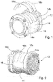
- Figs. 1 - 3 are different views of a railway axlebox bearing assembly and of a railway axlebox including a railway axlebox housing 10 ( Fig. 3 ) and a railway axlebox bearing assembly 12 according to the invention.
- the railway axlebox of Figs. 1 - 3 is of a three-piece type with a two-piece, split design link arm with an upper link arm housing 10a and a lower link arm housing 10b enabling a radial mounting with an additional sleeve 14 provided on the bearing.
- An outer ring 12a of a double-row tapered roller bearing is accommodated in the sleeve 14 and the radially outer surface of the sleeve 14 is mounting surface 16 configured to be mounted so as to face a radially inner mounting surface 16 of the axlebox housing 10, i.e. the upper link arm housing 10a and a lower link arm housing 10b.
- the mounting surface 16 includes two lateral rims protruding in a radial direction forming shoulders 14a, 14b for axial abutment of the housing 10 so as to avoid axial displacement of the sleeve 14 within the housing 10.
- the assembly further includes two strip-shaped spacer elements 18a, 18b configured to be mounted between the radially outer mounting surface 16 and the mounting surface 16 of an axlebox housing 10.
- the spacer elements 18a, 18b are placed parallel to each other with an axial offset and with their longitudinal directions oriented in a circumferential direction of the mounting surface 16.
- the placement and orientation of the spacer elements 18a, 18b in the circumferential direction of the sleeve 14 is set such that the spacer elements 18a, 18b are oriented upward, i.e. in the main load direction of the bearing.
- the two spacer elements 18a, 18b are made of electrically isolating material, for example in a plastic material, an elastomeric material or any suitable material or any material provided with an electrically insulating coating.
- the two spacer elements 18a, 18b are bent with a bending radius essentially corresponding to the curvature radius of the mounting surface 16 and the length of the spacer elements 18a, 18b is set such that the elements cover an angular sector of 120° of the radially outer mounting surface 16 in its circumferential direction.
- Fig. 4 is a detail of the sectional view of the railway axlebox according to Fig. 3 .
- the radially outer mounting surface 16 includes recesses 20a, 20b machined out of a main mounting surface 16 of the sleeve 14 and the recesses 20a, 20b match the shape of the spacer elements 18a, 18b such that the recesses 20a, 20b are capable of accommodating one of the spacer elements 18a, 18b, respectively.
- the depth of the recesses 20a, 20b is strictly smaller than the thickness of the spacer elements 18a, 18b such that the spacer elements 18a, 18b protrude over the main mounting surface 16 of the sleeve 14s when being mounted.
- the curvature radius of the concave inner surface of the spacer elements 18a, 18b corresponds to the curvature radius of the bottom surfaces of the recesses 20a, 20b and is strictly smaller than the curvature radius of the main mounting surface 16 and the curvature radius of the convex outer surface of the spacer elements 18a, 18b is strictly larger than the curvature radius of the main mounting surface 16.
- a gap or clearance 22 is formed between the main mounting surface 16 of the sleeve 14 and the radially inner surface of the upper housing 10 part.
- the spacer elements 18a, 18b fit tightly into the recesses 20a, 20b such that the recesses 20a, 20b hold the spacer elements 18a, 18b tightly in an axial and circumferential direction.
- the mounting may be done by press-fitting, sticking, screwing or clamping.
- the spacer elements 18a, 18b may be directly molded onto the radially outer surface of the sleeve 14.
- the recesses 20a, 20b are therefore anti-rotation means configured to avoid a slipping of the spacer elements 18a, 18b in relation to the mounting surface 16s.
- the anti-rotation means could be configured as recesses 20a, 20b, a bolt, pin or screw or by a glue or any combination of the latter alternatives.
- Fig. 5 is an exploded view of a railway axlebox bearing assembly 12 according to a second embodiment of the invention and Fig. 6 is a perspective view of the axlebox bearing assembly 12 according to Fig. 5 .
- the assembly includes a total of four strip-like spacer elements 18a, 18b, 18c, 18d each covering an angular sector of 180° of the radially outer mounting surface 16.
- Two of the spacer elements 18a, 18b, 18c, 18d are combined to form a group and are aligned in one radial plane and so as to cover, in sum, 360° of the circumference of the radially outer mounting surface 16, respectively.
- the recesses 20a, 20b accommodating the spacer elements 18a, 18b are extended to ring-shaped recess covering the entire circumference of the sleeve 14.
- Fig. 7 is an exploded view of a railway axlebox bearing assembly 12 according to a third embodiment of the invention.
- Fig. 8 is a perspective view of the axlebox bearing assembly 12 according to Fig. 7 and
- Fig. 9 is a detail of a sectional view of the railway axlebox according to Fig. 8 .
- the assembly includes a total of eight strip-like spacer elements 18a, 18b, 18c, 18d, 18e, 18f, 18g, 18h, wherein four of the spacer elements 18a, 18b, 18c, 18d correspond to the spacer elements 18a, 18b of the second embodiment of the invention and the remaining four of the spacer elements 18e, 18f, 18g, 18h are arc-shaped elements configured to be placed axially between the axial end surface of the sleeve 14 and the shoulders 14a, 14b of the sleeve 14 for axial abutment such that a direct contact between the axial surfaces of the spacer elements 18a - 18h and the housing 10 is avoided also in the axial direction as shown in Fig. 9 .
- Fig. 10 is a sectional view of a railway axlebox bearing assembly 12 according a fourth embodiment of the invention, which differs from the first embodiment of the invention in that the spacer elements 18a, 18b are made of sheet metal and in that 4 isolating O-rings made of rubber are provided on a top surface of the spacer elements 18a, 18b as additional spacer elements 18i, 18j, 18k, 181 to avoid electric contact and current return between the housing 10 and the sleeve 14.
- the metallic spacer elements 18a, 18b could be provided with an insulating coating.
- the additional spacer elements 18a - 181 help to solve some problems such as environmental corrosion, fretting corrosion and wear in an easy and cost-effective way. Further, the spacer elements 18a - 181 enable a better localization of the bearing load and an isolation of the bearing for current return and a prolongation of the life cycle for replacement of sleeve 14 and housing 10. These parts are easy to manufacture (sheet metal parts or plastic parts) and also easy to mount.
Landscapes
- Engineering & Computer Science (AREA)
- Mechanical Engineering (AREA)
- General Engineering & Computer Science (AREA)
- Rolling Contact Bearings (AREA)
- Mounting Of Bearings Or Others (AREA)
Claims (10)
- Eisenbahn-Achslager-Lageranordnung, die eine radiale äußere Montageoberfläche (16) beinhaltet, dazu ausgelegt, so montiert zu werden, dass sie einer radialen inneren Montageoberfläche (16) eines Achslagergehäuses (10) gegenüberliegt, dadurch gekennzeichnet, dass sie ferner mindestens zwei Distanzstückelemente (18a-18l) beinhaltet, die dazu ausgelegt sind, zwischen der radialen äußeren Montageoberfläche (16) und der Montageoberfläche (16) eines Achslagergehäuses (10) montiert zu werden, wobei die mindestens zwei Distanzstückelemente (18a-18l) einen Winkelsektor zwischen 120° und 180° der radialen äußeren Montageoberfläche (16) abdecken.
- Eisenbahn-Achslager-Lageranordnung nach Anspruch 1, dadurch gekennzeichnet, dass die mindestens zwei Distanzstückelemente (18a-18l) aus elektrisch isolierendem Material gefertigt sind.
- Eisenbahn-Achslager-Lageranordnung nach einem der vorstehenden Ansprüche, dadurch gekennzeichnet, dass eine äußere Buchse (14) dazu ausgelegt ist, einen äußeren Lagerring der Lageranordnung 12 aufzunehmen, wobei die radiale äußere Montageoberfläche (16) die radiale äußere Oberfläche der Buchse (14) ist.
- Eisenbahn-Achslager-Lageranordnung nach einem der vorstehenden Ansprüche, dadurch gekennzeichnet, dass die radiale äußere Montageoberfläche (16) Vertiefungen (20a, 20b) beinhaltet, die dazu ausgelegt sind, die mindestens zwei Distanzelemente (18a-18l) aufzunehmen.
- Eisenbahn-Achslager-Lageranordnung nach einem der vorstehenden Ansprüche, dadurch gekennzeichnet, dass sie Antirotationselemente beinhaltet, die dazu ausgelegt sind, ein Rutschen der Distanzelemente (18a-18l) in Relation zu den Montageoberflächen (16) zu vermeiden.
- Eisenbahn-Achslager-Lageranordnung nach einem der vorstehenden Ansprüche, dadurch gekennzeichnet, dass die mindestens zwei Distanzelemente (18a-18l) parallel zueinander platziert sind, wobei ihre Längsrichtungen in einer Umfangsrichtung der Montageoberfläche (16) ausgerichtet sind.
- Eisenbahn-Achslager-Lageranordnung nach einem der vorstehenden Ansprüche, dadurch gekennzeichnet, dass sie mindestens zwei Gruppen von Distanzelementen (18a-18l) beinhaltet, wobei die Distanzelemente (18a-18l) in einer Gruppe in einer radialen Ebene ausgerichtet sind und über den Umfang der äußeren Montageoberfläche (16) verteilt sind.
- Eisenbahn-Achslager-Lageranordnung nach Anspruch 7, dadurch gekennzeichnet, dass mindestens eine der Gruppen zwei Distanzelemente (18a-18l) beinhaltet, die Winkelsektoren abdecken, die in Summe 360° des Umfangs der radialen äußeren Montageoberfläche (16) abdecken.
- Eisenbahn-Achslager-Lageranordnung nach einem der vorstehenden Ansprüche, dadurch gekennzeichnet, dass die Diatanzelemente (18a-18l) Metallblechdistanzelemente (18a, 18b) beinhalten, wobei die Eisenbahn-Achslager-Lageranordnung (12) ferner isolierende O-Ringe (18a-18l) beinhaltet, die an den Distanzelementen (18a-18b) montiert sind, um einen elektrischen Kontakt zwischen den Metallblech-Distanzelementen (18a, 18l) und dem Achslagergehäuse (10) zu vermeiden.
- Eisenbahnachslager, das ein Eisenbahn-Achslagergehäuse (10) und eine Eisenbahnachslager-Lageranordnung (12) nach einem der vorstehenden Ansprüche beinhaltet, montiert in dem Eisenbahn-Achslagergehäuse (10) .
Priority Applications (3)
| Application Number | Priority Date | Filing Date | Title |
|---|---|---|---|
| EP16153213.0A EP3199419B1 (de) | 2016-01-28 | 2016-01-28 | Eisenbahnachslageranordnung mit montagefläche |
| CN201611144995.4A CN107042834B (zh) | 2016-01-28 | 2016-12-13 | 具有安装表面的轨道轴箱轴承单元 |
| US15/409,866 US10279821B2 (en) | 2016-01-28 | 2017-01-19 | Railway axlebox bearing assembly with mounting surface |
Applications Claiming Priority (1)
| Application Number | Priority Date | Filing Date | Title |
|---|---|---|---|
| EP16153213.0A EP3199419B1 (de) | 2016-01-28 | 2016-01-28 | Eisenbahnachslageranordnung mit montagefläche |
Publications (2)
| Publication Number | Publication Date |
|---|---|
| EP3199419A1 EP3199419A1 (de) | 2017-08-02 |
| EP3199419B1 true EP3199419B1 (de) | 2018-12-19 |
Family
ID=55272291
Family Applications (1)
| Application Number | Title | Priority Date | Filing Date |
|---|---|---|---|
| EP16153213.0A Active EP3199419B1 (de) | 2016-01-28 | 2016-01-28 | Eisenbahnachslageranordnung mit montagefläche |
Country Status (3)
| Country | Link |
|---|---|
| US (1) | US10279821B2 (de) |
| EP (1) | EP3199419B1 (de) |
| CN (1) | CN107042834B (de) |
Families Citing this family (3)
| Publication number | Priority date | Publication date | Assignee | Title |
|---|---|---|---|---|
| FR3060504B1 (fr) * | 2016-12-16 | 2022-01-07 | Skf Ab | Boite d'essieu pour bogie de vehicule ferroviaire et bogie de chemin de fer equipe d'une telle boite d'essieu |
| RU2677213C1 (ru) * | 2017-12-27 | 2019-01-15 | Федеральное государственное бюджетное образовательное учреждение высшего образования "Российский университет транспорта (МИИТ)" РУТ (МИИТ) | Ресурсосберегающая букса |
| US11052928B2 (en) * | 2018-05-31 | 2021-07-06 | Aktiebolaget Skf | Railcar adapter for connecting a railcar body to a bearing |
Family Cites Families (13)
| Publication number | Priority date | Publication date | Assignee | Title |
|---|---|---|---|---|
| US1952710A (en) * | 1931-04-27 | 1934-03-27 | Timken Roller Bearing Co | Roller bearing railway car axle mounting |
| US2176244A (en) * | 1936-05-19 | 1939-10-17 | Gen Motors Corp | Journal box |
| US2783102A (en) * | 1951-04-02 | 1957-02-26 | Skf Ind Inc | Railroad axle journal bearing construction |
| US5024449A (en) * | 1985-12-19 | 1991-06-18 | The Timken Company | Seal assembly for use with an overhang |
| CN201410960Y (zh) * | 2009-07-11 | 2010-02-24 | 兰州金牛轨道交通装备有限责任公司 | 一种管片车轴箱 |
| ES2397015B1 (es) * | 2010-11-18 | 2014-01-16 | Patentes Talgo, S.L. | Caja de grasa para rodales y bogies de ferrocarril. |
| EP2557017B1 (de) * | 2011-08-09 | 2018-10-10 | Aktiebolaget SKF | Achslager für ein Schienenfahrzeug |
| CN103889812A (zh) * | 2011-08-26 | 2014-06-25 | Skf公司 | 具有用于地回路的导电流体的、带旋转部分的组件 |
| JP2014070656A (ja) * | 2012-09-28 | 2014-04-21 | Jtekt Corp | 鉄道車両用軸受装置 |
| EP2833011A1 (de) * | 2013-07-31 | 2015-02-04 | Aktiebolaget SKF | Radsatzlageranordnung für ein Schienenfahrzeug und Radsatzlager mit einer solchen Radsatzlageranordnung |
| EP3169573B1 (de) * | 2014-07-17 | 2020-09-02 | Aktiebolaget SKF | Lagereinheit für einen radsatz eines schienenfahrzeuges, radsatz, schienenfahrzeug und wartungsverfahren |
| EP3168106B1 (de) * | 2015-11-13 | 2020-06-17 | Aktiebolaget SKF | Schienenfahrzeugadapter zum verbinden eines schienenfahrzeugkörpers mit einem lager |
| EP3168107B1 (de) * | 2015-11-13 | 2018-08-29 | Aktiebolaget SKF | Schienenfahrzeugadapter zum verbinden eines schienenfahrzeugkörpers mit einem lager |
-
2016
- 2016-01-28 EP EP16153213.0A patent/EP3199419B1/de active Active
- 2016-12-13 CN CN201611144995.4A patent/CN107042834B/zh active Active
-
2017
- 2017-01-19 US US15/409,866 patent/US10279821B2/en active Active
Non-Patent Citations (1)
| Title |
|---|
| None * |
Also Published As
| Publication number | Publication date |
|---|---|
| CN107042834B (zh) | 2019-12-06 |
| US10279821B2 (en) | 2019-05-07 |
| US20170217453A1 (en) | 2017-08-03 |
| EP3199419A1 (de) | 2017-08-02 |
| CN107042834A (zh) | 2017-08-15 |
Similar Documents
| Publication | Publication Date | Title |
|---|---|---|
| US10411545B2 (en) | Motor including busbar portion | |
| CA2894015C (en) | Electrically conductive bearing system and method | |
| EP3199419B1 (de) | Eisenbahnachslageranordnung mit montagefläche | |
| US9175728B2 (en) | Rolling bearing with integrated electrical shunt | |
| CN101595307B (zh) | 组装泵插入件的方法、插入件及真空泵 | |
| US6637942B2 (en) | Bearing assembly and method | |
| US11016113B2 (en) | Sensor bearing unit, assembly method of said unit and method for assembling said sensor bearing unit on shaft | |
| JP2009287658A (ja) | 電食防止用絶縁転がり軸受 | |
| CN104329364A (zh) | 特别用于驾驶杆的滚动轴承 | |
| US20110249925A1 (en) | Bearing assembly | |
| EP3001050A1 (de) | Wälzlager | |
| US10704596B2 (en) | Toroidal roller bearing | |
| US7658451B2 (en) | Aircraft wheel grease retainer and method for retrofitting the same | |
| EP2620662B1 (de) | Elektrische Maschine | |
| US20110255814A1 (en) | Bearing Assembly | |
| US9863466B2 (en) | Sliding bearing | |
| EP2975278B1 (de) | Wälzlager und Verfahren zur Herstellung eines solches Wälzlagers | |
| CN104518320B (zh) | 电气设备的连接装置 | |
| EP3026283A1 (de) | Wälzlageranordnung | |
| CN109027004B (zh) | 轴承衬套结构 | |
| CN218266806U (zh) | 一种轴承保护套及轴承 | |
| CN219733953U (zh) | 一种新型法兰关节轴承 | |
| EP2833011A1 (de) | Radsatzlageranordnung für ein Schienenfahrzeug und Radsatzlager mit einer solchen Radsatzlageranordnung | |
| US12378999B2 (en) | Insulated bearing | |
| US20250079783A1 (en) | Grounding brush assembly |
Legal Events
| Date | Code | Title | Description |
|---|---|---|---|
| PUAI | Public reference made under article 153(3) epc to a published international application that has entered the european phase |
Free format text: ORIGINAL CODE: 0009012 |
|
| STAA | Information on the status of an ep patent application or granted ep patent |
Free format text: STATUS: THE APPLICATION HAS BEEN PUBLISHED |
|
| AK | Designated contracting states |
Kind code of ref document: A1 Designated state(s): AL AT BE BG CH CY CZ DE DK EE ES FI FR GB GR HR HU IE IS IT LI LT LU LV MC MK MT NL NO PL PT RO RS SE SI SK SM TR |
|
| AX | Request for extension of the european patent |
Extension state: BA ME |
|
| STAA | Information on the status of an ep patent application or granted ep patent |
Free format text: STATUS: REQUEST FOR EXAMINATION WAS MADE |
|
| 17P | Request for examination filed |
Effective date: 20171122 |
|
| RBV | Designated contracting states (corrected) |
Designated state(s): AL AT BE BG CH CY CZ DE DK EE ES FI FR GB GR HR HU IE IS IT LI LT LU LV MC MK MT NL NO PL PT RO RS SE SI SK SM TR |
|
| RIC1 | Information provided on ipc code assigned before grant |
Ipc: B61F 15/20 20060101AFI20180425BHEP Ipc: F16C 27/06 20060101ALI20180425BHEP Ipc: B61F 15/02 20060101ALI20180425BHEP |
|
| GRAP | Despatch of communication of intention to grant a patent |
Free format text: ORIGINAL CODE: EPIDOSNIGR1 |
|
| STAA | Information on the status of an ep patent application or granted ep patent |
Free format text: STATUS: GRANT OF PATENT IS INTENDED |
|
| INTG | Intention to grant announced |
Effective date: 20180710 |
|
| GRAS | Grant fee paid |
Free format text: ORIGINAL CODE: EPIDOSNIGR3 |
|
| GRAA | (expected) grant |
Free format text: ORIGINAL CODE: 0009210 |
|
| STAA | Information on the status of an ep patent application or granted ep patent |
Free format text: STATUS: THE PATENT HAS BEEN GRANTED |
|
| AK | Designated contracting states |
Kind code of ref document: B1 Designated state(s): AL AT BE BG CH CY CZ DE DK EE ES FI FR GB GR HR HU IE IS IT LI LT LU LV MC MK MT NL NO PL PT RO RS SE SI SK SM TR |
|
| REG | Reference to a national code |
Ref country code: GB Ref legal event code: FG4D |
|
| REG | Reference to a national code |
Ref country code: CH Ref legal event code: EP |
|
| REG | Reference to a national code |
Ref country code: IE Ref legal event code: FG4D |
|
| REG | Reference to a national code |
Ref country code: DE Ref legal event code: R096 Ref document number: 602016008301 Country of ref document: DE |
|
| REG | Reference to a national code |
Ref country code: AT Ref legal event code: REF Ref document number: 1078356 Country of ref document: AT Kind code of ref document: T Effective date: 20190115 |
|
| REG | Reference to a national code |
Ref country code: NL Ref legal event code: MP Effective date: 20181219 |
|
| PG25 | Lapsed in a contracting state [announced via postgrant information from national office to epo] |
Ref country code: LV Free format text: LAPSE BECAUSE OF FAILURE TO SUBMIT A TRANSLATION OF THE DESCRIPTION OR TO PAY THE FEE WITHIN THE PRESCRIBED TIME-LIMIT Effective date: 20181219 Ref country code: HR Free format text: LAPSE BECAUSE OF FAILURE TO SUBMIT A TRANSLATION OF THE DESCRIPTION OR TO PAY THE FEE WITHIN THE PRESCRIBED TIME-LIMIT Effective date: 20181219 Ref country code: NO Free format text: LAPSE BECAUSE OF FAILURE TO SUBMIT A TRANSLATION OF THE DESCRIPTION OR TO PAY THE FEE WITHIN THE PRESCRIBED TIME-LIMIT Effective date: 20190319 Ref country code: LT Free format text: LAPSE BECAUSE OF FAILURE TO SUBMIT A TRANSLATION OF THE DESCRIPTION OR TO PAY THE FEE WITHIN THE PRESCRIBED TIME-LIMIT Effective date: 20181219 Ref country code: BG Free format text: LAPSE BECAUSE OF FAILURE TO SUBMIT A TRANSLATION OF THE DESCRIPTION OR TO PAY THE FEE WITHIN THE PRESCRIBED TIME-LIMIT Effective date: 20190319 Ref country code: FI Free format text: LAPSE BECAUSE OF FAILURE TO SUBMIT A TRANSLATION OF THE DESCRIPTION OR TO PAY THE FEE WITHIN THE PRESCRIBED TIME-LIMIT Effective date: 20181219 |
|
| REG | Reference to a national code |
Ref country code: LT Ref legal event code: MG4D |
|
| REG | Reference to a national code |
Ref country code: AT Ref legal event code: MK05 Ref document number: 1078356 Country of ref document: AT Kind code of ref document: T Effective date: 20181219 |
|
| PG25 | Lapsed in a contracting state [announced via postgrant information from national office to epo] |
Ref country code: RS Free format text: LAPSE BECAUSE OF FAILURE TO SUBMIT A TRANSLATION OF THE DESCRIPTION OR TO PAY THE FEE WITHIN THE PRESCRIBED TIME-LIMIT Effective date: 20181219 Ref country code: SE Free format text: LAPSE BECAUSE OF FAILURE TO SUBMIT A TRANSLATION OF THE DESCRIPTION OR TO PAY THE FEE WITHIN THE PRESCRIBED TIME-LIMIT Effective date: 20181219 Ref country code: AL Free format text: LAPSE BECAUSE OF FAILURE TO SUBMIT A TRANSLATION OF THE DESCRIPTION OR TO PAY THE FEE WITHIN THE PRESCRIBED TIME-LIMIT Effective date: 20181219 Ref country code: GR Free format text: LAPSE BECAUSE OF FAILURE TO SUBMIT A TRANSLATION OF THE DESCRIPTION OR TO PAY THE FEE WITHIN THE PRESCRIBED TIME-LIMIT Effective date: 20190320 |
|
| PG25 | Lapsed in a contracting state [announced via postgrant information from national office to epo] |
Ref country code: NL Free format text: LAPSE BECAUSE OF FAILURE TO SUBMIT A TRANSLATION OF THE DESCRIPTION OR TO PAY THE FEE WITHIN THE PRESCRIBED TIME-LIMIT Effective date: 20181219 |
|
| PG25 | Lapsed in a contracting state [announced via postgrant information from national office to epo] |
Ref country code: PL Free format text: LAPSE BECAUSE OF FAILURE TO SUBMIT A TRANSLATION OF THE DESCRIPTION OR TO PAY THE FEE WITHIN THE PRESCRIBED TIME-LIMIT Effective date: 20181219 Ref country code: IT Free format text: LAPSE BECAUSE OF FAILURE TO SUBMIT A TRANSLATION OF THE DESCRIPTION OR TO PAY THE FEE WITHIN THE PRESCRIBED TIME-LIMIT Effective date: 20181219 Ref country code: ES Free format text: LAPSE BECAUSE OF FAILURE TO SUBMIT A TRANSLATION OF THE DESCRIPTION OR TO PAY THE FEE WITHIN THE PRESCRIBED TIME-LIMIT Effective date: 20181219 Ref country code: PT Free format text: LAPSE BECAUSE OF FAILURE TO SUBMIT A TRANSLATION OF THE DESCRIPTION OR TO PAY THE FEE WITHIN THE PRESCRIBED TIME-LIMIT Effective date: 20190419 Ref country code: CZ Free format text: LAPSE BECAUSE OF FAILURE TO SUBMIT A TRANSLATION OF THE DESCRIPTION OR TO PAY THE FEE WITHIN THE PRESCRIBED TIME-LIMIT Effective date: 20181219 |
|
| PG25 | Lapsed in a contracting state [announced via postgrant information from national office to epo] |
Ref country code: RO Free format text: LAPSE BECAUSE OF FAILURE TO SUBMIT A TRANSLATION OF THE DESCRIPTION OR TO PAY THE FEE WITHIN THE PRESCRIBED TIME-LIMIT Effective date: 20181219 Ref country code: IS Free format text: LAPSE BECAUSE OF FAILURE TO SUBMIT A TRANSLATION OF THE DESCRIPTION OR TO PAY THE FEE WITHIN THE PRESCRIBED TIME-LIMIT Effective date: 20190419 Ref country code: SM Free format text: LAPSE BECAUSE OF FAILURE TO SUBMIT A TRANSLATION OF THE DESCRIPTION OR TO PAY THE FEE WITHIN THE PRESCRIBED TIME-LIMIT Effective date: 20181219 Ref country code: EE Free format text: LAPSE BECAUSE OF FAILURE TO SUBMIT A TRANSLATION OF THE DESCRIPTION OR TO PAY THE FEE WITHIN THE PRESCRIBED TIME-LIMIT Effective date: 20181219 Ref country code: SK Free format text: LAPSE BECAUSE OF FAILURE TO SUBMIT A TRANSLATION OF THE DESCRIPTION OR TO PAY THE FEE WITHIN THE PRESCRIBED TIME-LIMIT Effective date: 20181219 |
|
| REG | Reference to a national code |
Ref country code: CH Ref legal event code: PL |
|
| REG | Reference to a national code |
Ref country code: DE Ref legal event code: R097 Ref document number: 602016008301 Country of ref document: DE |
|
| PG25 | Lapsed in a contracting state [announced via postgrant information from national office to epo] |
Ref country code: LU Free format text: LAPSE BECAUSE OF NON-PAYMENT OF DUE FEES Effective date: 20190128 |
|
| REG | Reference to a national code |
Ref country code: BE Ref legal event code: MM Effective date: 20190131 |
|
| PLBE | No opposition filed within time limit |
Free format text: ORIGINAL CODE: 0009261 |
|
| STAA | Information on the status of an ep patent application or granted ep patent |
Free format text: STATUS: NO OPPOSITION FILED WITHIN TIME LIMIT |
|
| REG | Reference to a national code |
Ref country code: IE Ref legal event code: MM4A |
|
| PG25 | Lapsed in a contracting state [announced via postgrant information from national office to epo] |
Ref country code: DK Free format text: LAPSE BECAUSE OF FAILURE TO SUBMIT A TRANSLATION OF THE DESCRIPTION OR TO PAY THE FEE WITHIN THE PRESCRIBED TIME-LIMIT Effective date: 20181219 Ref country code: AT Free format text: LAPSE BECAUSE OF FAILURE TO SUBMIT A TRANSLATION OF THE DESCRIPTION OR TO PAY THE FEE WITHIN THE PRESCRIBED TIME-LIMIT Effective date: 20181219 Ref country code: MC Free format text: LAPSE BECAUSE OF FAILURE TO SUBMIT A TRANSLATION OF THE DESCRIPTION OR TO PAY THE FEE WITHIN THE PRESCRIBED TIME-LIMIT Effective date: 20181219 |
|
| 26N | No opposition filed |
Effective date: 20190920 |
|
| PG25 | Lapsed in a contracting state [announced via postgrant information from national office to epo] |
Ref country code: BE Free format text: LAPSE BECAUSE OF NON-PAYMENT OF DUE FEES Effective date: 20190131 |
|
| PG25 | Lapsed in a contracting state [announced via postgrant information from national office to epo] |
Ref country code: LI Free format text: LAPSE BECAUSE OF NON-PAYMENT OF DUE FEES Effective date: 20190131 Ref country code: CH Free format text: LAPSE BECAUSE OF NON-PAYMENT OF DUE FEES Effective date: 20190131 |
|
| PG25 | Lapsed in a contracting state [announced via postgrant information from national office to epo] |
Ref country code: IE Free format text: LAPSE BECAUSE OF NON-PAYMENT OF DUE FEES Effective date: 20190128 |
|
| PG25 | Lapsed in a contracting state [announced via postgrant information from national office to epo] |
Ref country code: SI Free format text: LAPSE BECAUSE OF FAILURE TO SUBMIT A TRANSLATION OF THE DESCRIPTION OR TO PAY THE FEE WITHIN THE PRESCRIBED TIME-LIMIT Effective date: 20181219 |
|
| PG25 | Lapsed in a contracting state [announced via postgrant information from national office to epo] |
Ref country code: TR Free format text: LAPSE BECAUSE OF FAILURE TO SUBMIT A TRANSLATION OF THE DESCRIPTION OR TO PAY THE FEE WITHIN THE PRESCRIBED TIME-LIMIT Effective date: 20181219 |
|
| PG25 | Lapsed in a contracting state [announced via postgrant information from national office to epo] |
Ref country code: MT Free format text: LAPSE BECAUSE OF NON-PAYMENT OF DUE FEES Effective date: 20190128 |
|
| GBPC | Gb: european patent ceased through non-payment of renewal fee |
Effective date: 20200128 |
|
| PG25 | Lapsed in a contracting state [announced via postgrant information from national office to epo] |
Ref country code: GB Free format text: LAPSE BECAUSE OF NON-PAYMENT OF DUE FEES Effective date: 20200128 |
|
| PG25 | Lapsed in a contracting state [announced via postgrant information from national office to epo] |
Ref country code: CY Free format text: LAPSE BECAUSE OF FAILURE TO SUBMIT A TRANSLATION OF THE DESCRIPTION OR TO PAY THE FEE WITHIN THE PRESCRIBED TIME-LIMIT Effective date: 20181219 |
|
| PG25 | Lapsed in a contracting state [announced via postgrant information from national office to epo] |
Ref country code: HU Free format text: LAPSE BECAUSE OF FAILURE TO SUBMIT A TRANSLATION OF THE DESCRIPTION OR TO PAY THE FEE WITHIN THE PRESCRIBED TIME-LIMIT; INVALID AB INITIO Effective date: 20160128 |
|
| PG25 | Lapsed in a contracting state [announced via postgrant information from national office to epo] |
Ref country code: MK Free format text: LAPSE BECAUSE OF FAILURE TO SUBMIT A TRANSLATION OF THE DESCRIPTION OR TO PAY THE FEE WITHIN THE PRESCRIBED TIME-LIMIT Effective date: 20181219 |
|
| P01 | Opt-out of the competence of the unified patent court (upc) registered |
Effective date: 20230513 |
|
| PGFP | Annual fee paid to national office [announced via postgrant information from national office to epo] |
Ref country code: DE Payment date: 20260127 Year of fee payment: 11 |
|
| PGFP | Annual fee paid to national office [announced via postgrant information from national office to epo] |
Ref country code: FR Payment date: 20260126 Year of fee payment: 11 |