EP3199421A1 - Funkkommunikationsvorrichtung, system und verfahren für eine schieneninfrastruktur - Google Patents
Funkkommunikationsvorrichtung, system und verfahren für eine schieneninfrastruktur Download PDFInfo
- Publication number
- EP3199421A1 EP3199421A1 EP17152760.9A EP17152760A EP3199421A1 EP 3199421 A1 EP3199421 A1 EP 3199421A1 EP 17152760 A EP17152760 A EP 17152760A EP 3199421 A1 EP3199421 A1 EP 3199421A1
- Authority
- EP
- European Patent Office
- Prior art keywords
- radio
- fra
- mra
- trackside
- board
- Prior art date
- Legal status (The legal status is an assumption and is not a legal conclusion. Google has not performed a legal analysis and makes no representation as to the accuracy of the status listed.)
- Granted
Links
Images


Classifications
-
- B—PERFORMING OPERATIONS; TRANSPORTING
- B61—RAILWAYS
- B61L—GUIDING RAILWAY TRAFFIC; ENSURING THE SAFETY OF RAILWAY TRAFFIC
- B61L15/00—Indicators provided on the vehicle or train for signalling purposes
- B61L15/0018—Communication with or on the vehicle or train
- B61L15/0027—Radio-based, e.g. using GSM-R
-
- B—PERFORMING OPERATIONS; TRANSPORTING
- B61—RAILWAYS
- B61L—GUIDING RAILWAY TRAFFIC; ENSURING THE SAFETY OF RAILWAY TRAFFIC
- B61L27/00—Central railway traffic control systems; Trackside control; Communication systems specially adapted therefor
- B61L27/70—Details of trackside communication
-
- B—PERFORMING OPERATIONS; TRANSPORTING
- B61—RAILWAYS
- B61L—GUIDING RAILWAY TRAFFIC; ENSURING THE SAFETY OF RAILWAY TRAFFIC
- B61L2205/00—Communication or navigation systems for railway traffic
- B61L2205/02—Global system for mobile communication - railways [GSM-R]
Definitions
- the present invention relates in general to the field of radio communications. More particularly, the present invention relates to a radio communication apparatus, system and method for a railway infrastructure.
- a railway infrastructure is generally provided with a radio communication system which comprises a radio apparatus situated on-board a train and a set of radio apparatuses distributed along the railway line.
- the on-board radio apparatus communicates with the radio apparatuses distributed along the line so as to transmit and receive:
- the flow of vital data has a relatively low throughput, typically of less than 1 Mb/s.
- the flow of non-vital data instead typically has a higher throughput, generally of between 10 Mb/s and 100 Mb/s.
- the radio apparatuses currently used in railway infrastructures are generally Wi-Fi apparatuses in compliance with the standard IEEE802.11.
- each radio apparatus comprises two radio communication units, one operating at 450 MHz and one operating in the ISM (Industrial Scientific Medical) band.
- the two bands are used for the transmission of data relating to two different train control systems, namely RC (Remote Control) and DP (Distributed Power).
- the known Wi-Fi radio apparatuses compliant with the standard IEEE802.11 currently used in railway infrastructures are not specifically designed for this application, and therefore have a number of drawbacks.
- the known radio apparatuses generally have a single radio unit architecture.
- redundancy mechanisms suitable for protecting the transmission of vital data it is therefore necessary to provide a pair of radio apparatuses, one of which has an operative function and the other a protective function.
- the two combined radio apparatuses are subject to mutual interference which negatively affects their performance in terms of signal/noise ratio.
- the handover procedures for transferring the connection of an on-board radio apparatus from a radio apparatus along the line to the next apparatus may cause a temporary interruption in the transmission of vital data. If this interruption is too long (more than 30 ms), the loss of vital data becomes critical and could have an impact on the safety of the train.
- the known radio apparatuses disadvantageously are unable to perform such short handover procedures ( ⁇ 30 ms).
- the known Wi-Fi radio apparatuses in compliance with the standard IEEE802.11 have a limited throughput, typically 100 Mb/s maximum.
- the known Wi-Fi radio apparatuses in compliance with the standard IEEE802.11 all have an identical structure, irrespective as to whether they are installed on-board the train or along the line.
- Any specific functional features which are required on-board on the train or along the line for example GPS location in the first case or access to the optical backbone network in the second case
- must be implemented separately for example installing a GPS locator cascade-connected to the on-board radio apparatus, or an optical module cascade-connected to each radio apparatus along the line).
- the known Wi-Fi radio apparatuses in compliance with the standard IEEE802.11 are generally monolithic, in the sense that - if one of their components is damaged - it is required to replace the entire apparatus. This disadvantageously increases the maintenance costs of the entire radio system.
- An object of the present invention is therefore to provide a radio communication apparatus, system and a method for a railway infrastructure which solve at least one of the aforementioned problems.
- an object of the present invention is to provide a radio communication apparatus, system and method for a railway infrastructure which (i) allow the transmission of vital data to be protected by means of a redundancy mechanism without requiring the installation of pairs of (operative/protective) radio devices on-board the trains and along the railway line and without causing a deterioration in the performance of the links between on-board radio apparatus and radio apparatuses along the line in terms of signal/noise ratio, latency or throughput, and (ii) minimize the risk of loss of vital data due to the known handover procedures.
- a radio apparatus suitable for being installed in a railway infrastructure (namely on a train or along the railway line), comprising two separate radio units, each of which is able to support the transmission and the reception of data via radio autonomously.
- the first radio unit is configured to operate in a first frequency range (for example 2.4 - 5 GHz), while a second radio unit is configured to operate in a second, lower, frequency range (for example 868-900 MHz).
- the radio apparatus therefore has a redundant structure (two radio units in a single apparatus) which, as will be described in greater detail below, allows the implementation of mechanisms for protecting the transmission of data (in particular vital data) without requiring duplication of the apparatuses. This allows the number of radio apparatuses in the system to be kept to a minimum, while reducing the installation time and overall cost thereof, without neglecting the safety of the trains and its passengers.
- the two radio units present in the radio apparatus moreover, since they operate in different frequency ranges, are not subject to mutual interference.
- the protection mechanisms which can be implemented by this redundancy structure of the radio apparatus therefore do not cause any deterioration of the signal/noise ratio due to this effect and therefore do no require either a reduction in the relative distance between the radio apparatuses installed along the railway line nor re-transmission mechanisms which would negatively affect the throughput and latency of the radio link between on-board side and trackside.
- a radio apparatus for a railway infrastructure comprising:
- the first radio unit and the second radio unit comprise respective hardware components which are identical and which are capable of operating substantially in all of said third frequency range and at least one programmable component capable of being programmed to control said hardware component so as to receive and/or transmit data using a first radio communication technology or standard operating in the first frequency range or a second radio communication technology or standard operating in the second frequency range.
- the hardware component capable of operating substantially in all of the third frequency range comprises a radiofrequency transceiver and at least one antenna.
- the radio apparatus has a modular hardware structure.
- the said radio apparatus comprises a base board in turn comprising a plurality of housings suitable for housing a corresponding plurality of modules selected from a set of interchangeable modules having identical hardware interfaces, the set of interchangeable modules comprising at least the first radio unit and the second radio unit, said radio apparatus being configurable as either a on-board radio apparatus suitable for being installed on board a train or as a trackside radio apparatus suitable for being installed along a railway line by suitably selecting said plurality of modules to be housed in said plurality of housings of said base board from said set of interchangeable modules.
- the set of interchangeable modules comprises, in addition to the first radio unit and the second radio unit:
- a radio communication system for a railway infrastructure comprising a on-board radio apparatus suitable for being installed on-board a train of the railway infrastructure and a plurality of trackside radio apparatuses suitable for being installed along a railway line along which the train travels, wherein:
- the trackside radio apparatuses are distributed along the railway line at a mutual distance substantially equal to D, the distance D being variable between a minimum value Dmin and a maximum value Dmax, and the first frequency range, the second frequency range, the minimum value Dmin and the maximum value Dmax are selected so that:
- the radio communication system further comprises a management apparatus configured to manage the on-board radio apparatus and the plurality of trackside radio apparatuses.
- the management apparatus is capable of configuring via software the first on-board radio unit and the first trackside radio unit to implement a first radio communication technology or standard operating in the first frequency range, and of configuring via software the second on-board radio unit and the second trackside radio units to implement a second radio communication technology or standard operating in the second frequency range.
- the management apparatus is also suitable for:
- the management apparatus is configured to, while the train travels along the railway line, control the first on-board radio unit of the on-board radio apparatus and the first trackside radio units of the plurality of trackside radio apparatuses to perform a handover procedure for moving the first radio link in the first frequency range from the first trackside radio unit of said trackside radio apparatus to the first trackside radio unit of the next trackside radio apparatus.
- the management apparatus is configured to, while the train travels along the railway line, comparing a signal power received at the first trackside radio unit of the trackside radio apparatus and also a signal power received at the first trackside radio unit of the next trackside radio apparatus with a threshold value RSSI(th) and determine whether said handover procedure is required based on the result of said comparing.
- the management apparatus is configured to measure a throughput of radio links between the on-board radio apparatus and the trackside radio apparatuses and, based on said throughput, adjust a frame transmission rate from or to the on-board radio apparatus and/or a signal power from or to the on-board radio apparatus.
- a method for transmitting and/or receiving data via radio in a railway infrastructure comprising a train and a railway line along which said train travels is provided, the method comprising:
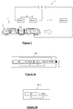
- Figure 1 shows in schematic form a radio communication system 1 for a railway infrastructure 2, according to embodiments of the present invention.
- the railway infrastructure 2 comprises a train 20 and a line (not shown for easier illustration) along which the train 20 travels in the direction indicated by the arrow F.
- the railway infrastructure 2 may be for example a metropolitan railway line, where the railway line has underground sections and/or sections passing inside a tunnel and/or along open sections.
- the radio communication system 1 comprises a on-board radio apparatus and a plurality of trackside radio apparatuses FRA#1, FRA#2 ... FRA#n.
- the on-board radio apparatus MRA is preferably installed on-board the train 20, while the trackside radio apparatuses FRA#1, FRA#2 ... FRA#n are preferably installed along the railway line along which the train 20 travels.
- the trackside radio apparatuses FRA#1, FRA#2 ... FRA#n are preferably distributed along the railway line at a mutual distance D from each other, variable between a minimum value Dmin and a maximum value Dmax.
- D, Dmin and Dmax are chosen according to criteria which will be described in detail in the remainder of the present description.
- the trackside radio apparatuses FRA#1, FRA#2 ... FRA#n may be situated at radio stations present on the line along which the train 20 travels. Alternatively, the trackside radio apparatuses FRA#1, FRA#2 ... FRA#n may be installed in special cabins situated in the vicinity of the railway line.
- the radio communication system 1 also comprises a management apparatus MA.
- the management apparatus MA is preferably situated at the control centre of the railway infrastructure 2 (not shown in the drawing).
- the management apparatus MA is connected to the on-board radio apparatus MRA and to each of the trackside radio apparatuses FRA#1, FRA#2 ... FRA#n by means of respective connection interfaces, for example by means of Gigabit Ethernet interfaces.
- the management apparatus MA is connected to each on-board or trackside radio apparatus by means of two different connection interfaces, so as to implement a redundancy mechanism for protection of the link.
- the on-board radio apparatus MRA, the trackside radio apparatuses FRA#1, FRA#2 ... FRA#n and the management apparatus MA have a modular hardware structure.
- each of these apparatuses preferably comprises a base board BB which has a system of housings, connectors and connections which are identical for all the apparatuses.
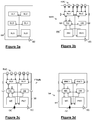
- the base board BB according to an embodiment is shown in Figure 3a . It preferably comprises six housings SL1, SL2, SL3, SL4, SL5, SL6, an electric connector EC suitable for connecting the board BB (and in particular the housing SL6 to an electric power supply source and a plurality of electrical connections which connect the housing SL6 to each of the housings SL1, SL2, SL3, SL4, SL5.
- Each apparatus MRA, FRA#1, FRA#2 ... FRA#n and MA further comprises modules which are housed on the base board BB, in particular in the housings SL1, SL2, SL3, SL4, SL5, SL6 of the base board BB.
- the modules of the on-board radio apparatus MRA, of the trackside radio apparatuses FRA#1, FRA#2 ... FRA#n and of the management apparatus MA are preferably chosen from a set of interchangeable modules (namely modules having a same hardware interface), comprising:
- the on-board radio apparatus MRA, the trackside radio apparatuses FRA#1, FRA#2 ... FRA#n and the management apparatus MA comprise different combinations of the modules listed above.
- the on-board radio apparatus MRA preferably comprises a first radio unit RU1, a second radio unit RU2, a network switch NS and a programmable AC/DC converter PAD housed on a base board BB, in particular in the housings SL1, SL2, SL3 and SL6, respectively.
- the on-board radio apparatus MRA also comprises a test board DB, also housed on the base board BB (in particular, in the housing SL4).
- the on-board radio apparatus MRA preferably also comprises a module GM also housed on the base board BB (in particular in the housing SL5).
- the network switch NS is connected to the radio unit RU1, RU2, to the GPS module GM and to the test board DB (if present), preferably by means of respective Ethernet connections.
- the on-board radio apparatus MRA further comprises preferably, for each radio unit RU1, RU2, at least one radio antenna connector.
- the on-board radio apparatus MRA preferably comprises six radio antenna connectors RAC (namely three for each radio unit RU1, RU2) which allow each radio unit to implement a MIMO (Multiple Input Multiple Output) 3x3 connection.
- the management apparatus MA preferably also has a hardware structure similar to that of the trackside radio apparatuses FRA#k, with the sole difference that it does not have radio antenna connectors RAC and that, in the housings SI1, SI2, it comprises a first radio network controller RNC1 and a second radio network controller RNC2 instead of the radio units RU1, RU2.
- both the on-board radio apparatus MRA and each of the trackside radio apparatuses FRA#k advantageously has a redundant structure (two radio units RU1, RU2 in a single apparatus) which, as will be described in greater detail below, allows the implementation of mechanisms for protecting the transmission of data (in particular vital data) without requiring the duplication of the apparatuses.
- This allows the number of radio apparatuses in the system to be kept to a minimum, while reducing the installation time and overall cost thereof, without neglecting the safety of the train and its passengers.
- the inventors in particular have estimated that the number of apparatuses to be installed may be advantageously reduced by more than 50% compared to the case of known radio apparatuses, with a saving of about 80% in terms of costs for installation of the system.
- the modular structure of the apparatuses MRA, FRA#k and MA advantageously reduces the costs of maintenance of the radio communication system 1 since, in the event of a fault, it is sufficient to replace the faulty module with an identical one, without making any modifications to the rest of the apparatus and without having to fully replace it.
- each (on-board or trackside) radio apparatus may be provided with modules which perform specific functions required on-board on the train (for example the GPS module GM which performs the geolocation function in the on-board radio apparatus MRA) and along the railway line (for example, the media converter MC and the optical converter OC which perform the function of accessing the backbone network in the trackside radio apparatuses FRA#k).
- modules which perform specific functions required on-board on the train for example the GPS module GM which performs the geolocation function in the on-board radio apparatus MRA
- the media converter MC and the optical converter OC which perform the function of accessing the backbone network in the trackside radio apparatuses FRA#k.
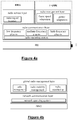
- the apparatuses MRA, FRA#1, FRA#2 ... FRA#n and MA preferably have a two-layer architecture.
- the software architecture of the on-board radio apparatus MRA preferably comprises a radio communication layer and a radio service layer
- the software architecture of each trackside radio apparatus FRA#k preferably comprises a radio communication layer and a radio management layer.
- the radio communication layer common to the software architecture of the on-board radio apparatus MRA and of each trackside radio apparatus FRA#k is preferably designed to execute the protocols of the radio communication technology or standard used by the radio unit of the apparatus.
- it comprises a radio operating system which performs the following functions:
- the radio communication layer preferably also comprises a plurality (three, according to an advantageous embodiment) of radio plug-ins, each of which comprises a software component able to enable radio communication in a respective subrange of the range 40 MHz - 6 GHz supported by the hardware of the radio unit.
- the radio communication layer preferably comprises:
- the radio service layer of the on-board radio apparatus MRA is configured to implement at least one specific service of the on-board side.
- the radio service layer of the on-board radio apparatus is preferably configured to implement a service for location of the radio signal, which will be described in greater detail hereinbelow.
- each trackside radio apparatus FRA#k it is preferably configured to implement the management of the on-board radio apparatus MRA and the trackside radio apparatuses FRA#k so as to optimize the performance of the radio links between the trackside and the on-board side.
- the radio management layer of each trackside radio apparatus FRA#k is preferably configured to adapt the transmission rate of the video frames and adapt the signal power, as will be described in greater detail hereinbelow.
- the management apparatus MA preferably also has a two-layer software architecture which preferably comprises a network communication layer and a global radio management layer.
- the network communication layer preferably comprises a network operating system configured for management and control of the layer L2 and L3 traffic generated by the on-board and trackside radio apparatuses.
- the overall radio management layer is configured to implement one or more of the following services:
- the on-board radio apparatus MRA comprises a first radio unit RU1(MRA) and a second radio unit RU2(MRA), which are also referred to below more simply as “first on-board radio unit” and “second on-board radio unit”.
- data flows for example a vital data flow and a non-vital data flow
- the management apparatus MA preferably configures the first radio unit RU1(MRA) as client and the first trackside radio units RU1(FRA#k) as servers according to this first radio communication technology or standard. In this way, the configuration of the radio links between trackside and on-board side in the first frequency range is established by the trackside radio apparatuses FRA#k, while the on-board radio apparatus MRA cannot modify the configuration of these radio links.
- the management apparatus MA preferably configures the second radio unit RU2(MRA) as server and the second trackside radio units RU2(FRA#k) as clients according to this second radio communication technology or standard.
- the configuration of the radio links between trackside and on-board side in the second frequency range is established by the on-board radio apparatus MRA, while the trackside radio apparatuses FRA#k cannot modify the configuration of these radio links.
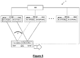
- the first frequency range and the mutual distance D between the trackside radio apparatuses FRA#1, FRA#2, ... FRA#n along the railway line are chosen so that, while it travels in the direction of the arrow F, the first on-board radio unit RU1(MRA) is able to set up a radio link with the first trackside radio unit RU1(FRA#k) of one trackside radio apparatus FRA#k at a time, namely that which is closest to it (for example FRA#1 in Figure 5 ).
- the distance D between trackside radio apparatuses FRA#1, FRA#2 ... FRA#n along the railway line is variable between a minimum value Dmin (along sections with high electromagnetic disturbance and interference, for example inside tunnels) and a maximum value Dmax (along sections with low electromagnetic disturbance and interference, such as open sections).
- Dmin an electromagnetic disturbance and interference
- Dmax an electromagnetic disturbance and interference
- Figure 5 shows the second on-board radio unit RU2(MRA) simultaneously connected both to the second trackside radio unit RU2(FRA#1) and to the second trackside radio unit RU2(FRA#2).
- the second on-board radio unit RU2(MRA) is able to set up links with any second trackside radio unit RU2(FRA#k) which is situated within a distance of about 20 km.
- the management apparatus MA preferably controls the first on-board radio unit RU1(MRA) and the first trackside radio units (RU1(FRA#k) so that they perform a handover procedure, which allows the link in the first frequency range to be moved from the first trackside radio unit (FRA#k) of a trackside radio apparatus FRA#k to the first trackside radio unit RU1(FRA#k+1) of the next trackside radio apparatus FRA#k+1 along the direction of the arrow F.
- Figure 5 shows by way of example the handover from the first trackside radio unit RU1(FRA#1) to the next first trackside radio unit RU1(FRA#2), indicated schematically by the arrow F'.
- the continuity of the radio link between on-board side and trackside in the second frequency range is advantageously ensured without the need to perform any handover procedure. While in fact the train 20 moves, the radio link between the second on-board radio unit RU2(MRA) and the second trackside radio unit RU2(FRA#k) - which between the units currently connected is furthest away in the opposite direction to that of the arrow F - will be interrupted, but the continuity of the radio link in the second frequency range is in any case ensured by the other K-1 radio links to the other K-1 second trackside radio units RU2(FRA#k) which are still located in the coverage area of the second on-board radio unit RU2(MRA).
- vital data such as signalling messages for managing, controlling and protecting the railway traffic, for example signalling messages of the CBTC system
- non-vital data such as video data provided by any closed-circuit TV cameras present on the train 20, or service information for passengers, etc.
- the vital data is transmitted both with a high throughput on the radio link between on-board side and trackside in the first higher frequency range, and with a lower throughput on the K radio links between on-board side and trackside in the second lower frequency range. If therefore, during the course of the handover procedure of the radio link between on-board side and trackside in the first frequency range, there is an interruption in the transmission of vital data, said data nevertheless continues to be exchanged between on-board side and trackside (albeit with a lower throughput) by the K radio links in the second lower frequency range. In other words, the duration of the vital data handover procedure is reduced substantially to zero.
- the transmission of the vital data on the K radio links in the second lower frequency range is advantageously very robust since it is redundant and intrinsically not affected by handover procedures. It constitutes therefore a very reliable protection system.
- the transmission of vital data is therefore advantageously protected by means of a redundancy mechanism which does not require the installation of pairs of (operative/protective) radio devices on-board the trains and along the railway line.
- the transmission of vital and non-vital data in the first frequency range and the transmission of vital data in the second frequency range are not subject to mutual interference, precisely because they are performed in different frequency ranges. There is therefore no deterioration in terms of signal-noise ratio due to this effect and therefore it is not required either to reduce the distance D between the trackside radio apparatuses FRA#k nor to employ any re-transmission mechanism which would worsen the throughput and the latency of the radio link between on-board side and trackside.
- the management apparatus MA preferably configures as active radio unit on the on-board side the first on-board radio unit RU1(MRA), setting it as client using the first radio communication technology or standard operating in the first frequency range, for example Wi-Fi in the frequency range 2.4 - 5 GHz (step 601).
- the management apparatus MA preferably configures as active radio unit on the trackside the first fixed radio unit RU1(FRA#k), setting it as server using the first radio communication technology or standard (step 602).
- the first on-board radio unit RU1(MRA) therefore is preferably associated with the first trackside radio unit RU1(FRA#k) and communicates to the management apparatus MA the corresponding radio association request (step 603).
- the second on-board radio unit RU2(MRA) preferably is associated with the second trackside radio unit RU2(FRA#k) and communicates to the management apparatus MA the corresponding radio association request (step 604).
- the management apparatus MA concludes that the first on-board radio unit RU1(MRA) is not connected to any first trackside radio unit (step 606).
- the on-board radio apparatus MRA is not connected to any trackside radio apparatus FRA#1, FRA#2, ... FRA#n in the first frequency range, namely the transmission of vital and non-vital data in the first frequency range is interrupted.
- the management apparatus MA preferably configures as active radio unit on the on-board side the second on-board radio unit RU2(MRA), setting it as server using the second radio communication technology or standard operating in the second frequency range, for example Lo-Ra in the frequency range 868-900 MHz (step 607).
- the management apparatus MA preferably configures as active radio unit on the trackside the second trackside radio unit RU2(FRA#k), setting it as client using the second radio communication technology or standard (step 608).
- the communication system 1 thus starts to use as vital data the data transmitted with low throughput in the second lower frequency range.
- the transmission of the non-vital data continues instead to be interrupted, until the radio link between trackside and on-board side in the first frequency range is restored.
- the management apparatus MA establishes that a procedure for handover from the apparatus FRA#k to the apparatus FRA#k+1 is required (step 609).
- the management apparatus MA preferably leaves as active radio unit on the on-board side the first on-board radio unit RU1(MRA) set as client (step not shown) and further preferably configures as active radio unit on the trackside the next first trackside radio unit RU1(FRA#k+1), setting it as server.
- the first on-board radio unit RU1(MRA) carries out its procedure for handover from the first trackside radio unit RU1(FRA#k) to the next first radio unit RU1(FRA#k+1) in the direction F. If the handover procedure is carried out correctly, the transmission of the vital and non-vital data continues therefore without interruption in the first frequency range.
- the management apparatus MA preferably configures as active radio unit on the trackside also the next second on-board radio unit RU2(FRA#k+1) in the direction F, setting it as client (step 611) and preferably configures as active radio unit on the on-board side also the second on-board radio unit RU2(MRA), setting it as server (step 612).
- the communication system 1 uses as vital data not only the data transmitted with high throughput in the first higher frequency range, but also the data transmitted with low throughput in the second lower frequency range. This advantageously ensures that there is no loss of vital data during the handover procedure, irrespective of its duration which - owing to this redundancy mechanism - is basically reduced to zero.
- the management apparatus MA establishes that for the moment no further handover procedure is required (step 613).
- the active radio unit on the on-board side therefore remains the first on-board radio unit RU1(MRA) and the active radio unit on the trackside remains the first trackside radio unit RU1(FRA#k) (step not shown).
- the management apparatus MA establishes that for the moment a procedure for handover is not required (step 614).
- the management apparatus MA however preferably configures as active radio unit on the trackside the first trackside radio unit RU1(FRA#k+1), setting it as server (step 615). In this way, advantageously the coverage of the on-board radio apparatus MRA is extended as far as possible, and the number of handovers is minimized, with a consequent reduction of computational resources and greater stability of the entire radio communication system 1.
- adaptation of the frame transmission rate advantageously allows the transmission rate of the video frames generated by any closed-circuit TV cameras present on the train 20 to be adapted so as to ensure that the throughput of high-priority packets (for example, packets which transport vital data such as signalling messages of the CBTC system) does not fall below a guaranteed minimum value.
- high-priority packets for example, packets which transport vital data such as signalling messages of the CBTC system
- the management apparatus MA collects information about the throughput of the (vital and non-vital) data transmitted overall between the on-board radio apparatus MRA and the trackside radio apparatus FRA#k (step 701).
- the management apparatus MA preferably consults a list of the active radio units on the trackside which are communicating with the on-board radio apparatus MRA and for each of them establishes the throughput THR(MRA ⁇ FRA#k) from the on-board radio apparatus MRA and the throughput THR(FRA#k ⁇ MRA) to the on-board radio apparatus MRA (for example using the SNMP protocol).
- the management apparatus MA then preferably analyzes the throughput values THR(MRA ⁇ FRA#k) and THR(FRA#k ⁇ MRA) read and processes them in order to correct suitably the transmission rate of the video frames.
- the management apparatus MA preferably compares the throughput THR(MRA ⁇ FRA#k) from the on-board radio apparatus MRA and the throughput THR(FRA#k ⁇ MRA) to the on-board radio apparatus MRA with three different threshold values TH1, TH2, TH3 (step 702).
- TH1 1 Mb/s
- TH2 5 Mb/s
- TH3 10 Mb/s.
- the first threshold TH1 preferably represents the minimum throughput guaranteed for the flow of high-priority packets in each of the two directions (from on-board side to trackside and vice versa).
- the management apparatus MA preferably sets to zero the frame transmission rate (step 703) and, preferably, sets the status of an alarm to the "critical" value (step 704).
- the management apparatus MA preferably sets the frame transmission rate to a first value v1 (for example 10 frames/second) (step 705) and, preferably, sets the status of an alarm to the "high" value (step 706).
- v1 for example 10 frames/second
- the management apparatus MA preferably sets the frame transmission rate to a second value v2 (for example 20 frames/second) (step 707) and, preferably, sets the status of an alarm to the "low" value (step 708).
- v2 for example 20 frames/second
- the management apparatus MA preferably sets the frame transmission rate to a third value v3 (for example 30 frames/second) (step 709) and, preferably, sets the status of an alarm to the "alert" value (step 710).
- v3 for example 30 frames/second
- the radio communication system 1 is advantageously able to ensure that the throughput of the vital data does not fall below a minimum value.
- the transmission of this data with a throughput which does not fall below a minimum value advantageously ensures that the train 20 is driven in a safe and reliable manner.
- the safety of the entire railway infrastructure is therefore advantageously increased.
- the management apparatus MA collects information about the power of the signal received from the on-board radio apparatus MRA and the trackside radio apparatuses FRA#k (step 801).
- the management apparatus MA preferably consults a list of the active radio units on the trackside which is communicating with the on-board radio apparatus MRA and, for each of them, determines the power of the signal RSSI(FRA#k ⁇ MRA) which the active radio unit on the trackside radio apparatus FRA#k is receiving from the on-board radio apparatus MRA and the power of the signal RSSI(MRA ⁇ FRA#k) which the on-board radio apparatus MRA is receiving from that active unit on the trackside radio apparatus FRA#k.
- the management apparatus MA then preferably analyzes the power values of the signal RSSI(FRA#k ⁇ MRA) and RSSI(MRA ⁇ FRA#k) which have been read and processes them so as to correct suitably the transmission power values of the signal at the on-board radio apparatus MRA and/or at the on-board radio apparatus MRA and/or at the trackside radio apparatuses FRA#n.
- the management apparatus MA preferably compares the values RSSI(FRA#k ⁇ MRA) and RSSI(MRA ⁇ FRA#k) with a threshold RSSI(TH), for example equal to -70 dB (step 802).
- the management apparatus MA preferably increases the transmission power of the signal Ptx(MRA) at the on-board radio apparatus MRA (step 803).
- the management apparatus MA preferably increases the transmission power of the signal Ptx(FRA#k) at the active radio unit on the trackside radio apparatus FRA#k (step 804).
- the radio service layer of the software architecture of the on-board radio apparatus MRA preferably comprises a radio signal location service which allows the radio signal emitted by the on-board radio apparatus MRA to be located in real time. More particularly, this service allows the data relating to geolocation to be combined with the data relating to the power of the signal received RSSI, so as to provide a geographical map of the RSSI signals.
- the management apparatus MA consults a list of the active radio units on the on-board side and, for each of them, sends a request to receive current RSSI and geographical coordinates (step 901).
- each on-board radio apparatus MRA which has received the request reads its geographical coordinates by means of its GPS (Global Positioning System) module GM, for example in terms of altitude, latitude and longitude (step 902).
- GPS Global Positioning System
- Each on-board radio apparatus MRA then preferably combines the coordinates with the current RSSI and sends off all the data to the management apparatus MA (step 903).
- the management apparatus 903 analyzes the data received and displays it on a map (step 904) which shows the geographical distribution of the RSSI values for the on-board radio apparatus MRA.
- the radio communication system 1 for a railway infrastructure offers therefore various advantages.
- the apparatuses may be advantageously configured so that they are able to support any radio communication technology or standard, without the need for any modification of their hardware.
Landscapes
- Engineering & Computer Science (AREA)
- Mechanical Engineering (AREA)
- Mobile Radio Communication Systems (AREA)
Applications Claiming Priority (1)
| Application Number | Priority Date | Filing Date | Title |
|---|---|---|---|
| ITUB2016A000294A ITUB20160294A1 (it) | 2016-01-29 | 2016-01-29 | Apparato e sistema di comunicazione radio per un'infrastruttura ferroviaria |
Publications (2)
| Publication Number | Publication Date |
|---|---|
| EP3199421A1 true EP3199421A1 (de) | 2017-08-02 |
| EP3199421B1 EP3199421B1 (de) | 2020-05-06 |
Family
ID=55919869
Family Applications (1)
| Application Number | Title | Priority Date | Filing Date |
|---|---|---|---|
| EP17152760.9A Active EP3199421B1 (de) | 2016-01-29 | 2017-01-24 | Funkkommunikationsvorrichtung, system und verfahren für eine schieneninfrastruktur |
Country Status (3)
| Country | Link |
|---|---|
| EP (1) | EP3199421B1 (de) |
| DK (1) | DK3199421T3 (de) |
| IT (1) | ITUB20160294A1 (de) |
Cited By (5)
| Publication number | Priority date | Publication date | Assignee | Title |
|---|---|---|---|---|
| CN109451464A (zh) * | 2018-11-28 | 2019-03-08 | 卡斯柯信号有限公司 | 一种基于LoRA通信的有轨电车车地通信系统 |
| IT201900022629A1 (it) | 2019-12-02 | 2021-06-02 | Comesvil S P A | Sistema di telecomunicazioni per un'infrastruttura ferroviaria |
| CN113734234A (zh) * | 2020-05-30 | 2021-12-03 | 通号通信信息集团上海有限公司 | 一种基于LoRa的列尾装置及用于该装置的通信方法 |
| GB2598173A (en) * | 2020-02-18 | 2022-02-23 | Mtr Corporation Ltd | System and apparatus for monitoring underground railway tunnel |
| CN114261433A (zh) * | 2021-12-07 | 2022-04-01 | 浙江众合科技股份有限公司 | 一种多功能的资源目标控制器 |
Families Citing this family (1)
| Publication number | Priority date | Publication date | Assignee | Title |
|---|---|---|---|---|
| US11305796B1 (en) | 2021-10-20 | 2022-04-19 | Bnsf Railway Company | System and method for remote device monitoring |
Citations (3)
| Publication number | Priority date | Publication date | Assignee | Title |
|---|---|---|---|---|
| US20030151520A1 (en) | 2002-02-11 | 2003-08-14 | Kraeling Mark Bradshaw | Railroad communication system |
| EP1603280A2 (de) * | 2004-06-01 | 2005-12-07 | GSP Sprachtechnologie Gesellschaft für elektronische Sprachsysteme mbH | Verfahren zur drahtlosen Übertragung von Information |
| AU2009251096A1 (en) * | 2008-12-22 | 2010-07-08 | Technological Resources Pty. Limited | Rail Transport System |
-
2016
- 2016-01-29 IT ITUB2016A000294A patent/ITUB20160294A1/it unknown
-
2017
- 2017-01-24 EP EP17152760.9A patent/EP3199421B1/de active Active
- 2017-01-24 DK DK17152760.9T patent/DK3199421T3/da active
Patent Citations (3)
| Publication number | Priority date | Publication date | Assignee | Title |
|---|---|---|---|---|
| US20030151520A1 (en) | 2002-02-11 | 2003-08-14 | Kraeling Mark Bradshaw | Railroad communication system |
| EP1603280A2 (de) * | 2004-06-01 | 2005-12-07 | GSP Sprachtechnologie Gesellschaft für elektronische Sprachsysteme mbH | Verfahren zur drahtlosen Übertragung von Information |
| AU2009251096A1 (en) * | 2008-12-22 | 2010-07-08 | Technological Resources Pty. Limited | Rail Transport System |
Non-Patent Citations (1)
| Title |
|---|
| JIA-YI ZHANG ET AL: "A Multi-Mode Multi-Band and Multi-System-Based Access Architecture for High-Speed Railways", VEHICULAR TECHNOLOGY CONFERENCE FALL (VTC 2010-FALL), 2010 IEEE 72ND, 1 September 2010 (2010-09-01), Piscataway, NJ, USA, pages 1 - 5, XP055311671, ISBN: 978-1-4244-3573-9, DOI: 10.1109/VETECF.2010.5594223 * |
Cited By (7)
| Publication number | Priority date | Publication date | Assignee | Title |
|---|---|---|---|---|
| CN109451464A (zh) * | 2018-11-28 | 2019-03-08 | 卡斯柯信号有限公司 | 一种基于LoRA通信的有轨电车车地通信系统 |
| IT201900022629A1 (it) | 2019-12-02 | 2021-06-02 | Comesvil S P A | Sistema di telecomunicazioni per un'infrastruttura ferroviaria |
| EP3831690A1 (de) | 2019-12-02 | 2021-06-09 | Comesvil S.p.A. | Telekommunikationssystem und -verfahren der eisenbahninfrastruktur |
| GB2598173A (en) * | 2020-02-18 | 2022-02-23 | Mtr Corporation Ltd | System and apparatus for monitoring underground railway tunnel |
| CN113734234A (zh) * | 2020-05-30 | 2021-12-03 | 通号通信信息集团上海有限公司 | 一种基于LoRa的列尾装置及用于该装置的通信方法 |
| CN114261433A (zh) * | 2021-12-07 | 2022-04-01 | 浙江众合科技股份有限公司 | 一种多功能的资源目标控制器 |
| CN114261433B (zh) * | 2021-12-07 | 2023-11-14 | 浙江众合科技股份有限公司 | 一种多功能的资源目标控制器 |
Also Published As
| Publication number | Publication date |
|---|---|
| ITUB20160294A1 (it) | 2017-07-29 |
| DK3199421T3 (da) | 2020-08-17 |
| EP3199421B1 (de) | 2020-05-06 |
Similar Documents
| Publication | Publication Date | Title |
|---|---|---|
| EP3199421B1 (de) | Funkkommunikationsvorrichtung, system und verfahren für eine schieneninfrastruktur | |
| US11909507B2 (en) | Using low earth orbit satellites to overcome latency | |
| JP6734359B2 (ja) | 衛星通信の位置報告およびページング | |
| JP2019517186A (ja) | 衛星通信のためのハンドオフ | |
| ES2795454T3 (es) | Sistema de telecomunicación de banda ancha entre uno o varios centros de control y una o varias unidades móviles | |
| US10284292B2 (en) | Systems and methods for communication link redundancy for distributed antenna systems | |
| BR112017023570B1 (pt) | Handoff para comunicação por satélite | |
| CN106464344A (zh) | 用于移动平台的多调制解调器通信系统和方法 | |
| US20250254587A1 (en) | Apparatus and method for service continuity in non-terrestrial network | |
| KR20190117693A (ko) | Das에서 집합 캐리어들의 라우팅 | |
| Zhao et al. | LTE-M system performance of integrated services based on field test results | |
| CN112637815B (zh) | 一种支持4g/5g双模在线的无人机数图传输通信设备 | |
| JP6917154B2 (ja) | 無線列車制御システム | |
| US9271190B2 (en) | Remotely managed data radios including remote management capabilities | |
| HK1237729A1 (en) | Radio communication apparatus, system and method for a railway infrastructure | |
| HK1237729B (en) | Radio communication apparatus, system and method for a railway infrastructure | |
| US9801194B2 (en) | Adaptation of a telecommunications network to changes in configuration | |
| EP3831690A1 (de) | Telekommunikationssystem und -verfahren der eisenbahninfrastruktur | |
| JP2009272905A (ja) | 列車無線システム | |
| US20230373544A1 (en) | Apparatus and method for controlling train in wireless communication system | |
| KR20200061884A (ko) | 분산 안테나 시스템 및 분산 안테나 시스템의 서비스 방법 | |
| JP2016146594A (ja) | 基地局および無線通信システム | |
| CN116896696A (zh) | 基于主机的光频率调谐 | |
| EP4657959A1 (de) | Sidelink-kommunikationsverfahren für kritischen kommunikationsdienst und vorrichtung dafür | |
| KR20230160712A (ko) | 무선 통신 시스템에서 열차 제어를 위한 장치 및 방법 |
Legal Events
| Date | Code | Title | Description |
|---|---|---|---|
| PUAI | Public reference made under article 153(3) epc to a published international application that has entered the european phase |
Free format text: ORIGINAL CODE: 0009012 |
|
| STAA | Information on the status of an ep patent application or granted ep patent |
Free format text: STATUS: THE APPLICATION HAS BEEN PUBLISHED |
|
| AK | Designated contracting states |
Kind code of ref document: A1 Designated state(s): AL AT BE BG CH CY CZ DE DK EE ES FI FR GB GR HR HU IE IS IT LI LT LU LV MC MK MT NL NO PL PT RO RS SE SI SK SM TR |
|
| AX | Request for extension of the european patent |
Extension state: BA ME |
|
| STAA | Information on the status of an ep patent application or granted ep patent |
Free format text: STATUS: REQUEST FOR EXAMINATION WAS MADE |
|
| 17P | Request for examination filed |
Effective date: 20180126 |
|
| RBV | Designated contracting states (corrected) |
Designated state(s): AL AT BE BG CH CY CZ DE DK EE ES FI FR GB GR HR HU IE IS IT LI LT LU LV MC MK MT NL NO PL PT RO RS SE SI SK SM TR |
|
| REG | Reference to a national code |
Ref country code: HK Ref legal event code: DE Ref document number: 1237729 Country of ref document: HK |
|
| RIC1 | Information provided on ipc code assigned before grant |
Ipc: B61L 27/00 20060101ALI20191015BHEP Ipc: B61L 15/00 20060101AFI20191015BHEP |
|
| GRAP | Despatch of communication of intention to grant a patent |
Free format text: ORIGINAL CODE: EPIDOSNIGR1 |
|
| STAA | Information on the status of an ep patent application or granted ep patent |
Free format text: STATUS: GRANT OF PATENT IS INTENDED |
|
| INTG | Intention to grant announced |
Effective date: 20191209 |
|
| GRAS | Grant fee paid |
Free format text: ORIGINAL CODE: EPIDOSNIGR3 |
|
| GRAA | (expected) grant |
Free format text: ORIGINAL CODE: 0009210 |
|
| STAA | Information on the status of an ep patent application or granted ep patent |
Free format text: STATUS: THE PATENT HAS BEEN GRANTED |
|
| AK | Designated contracting states |
Kind code of ref document: B1 Designated state(s): AL AT BE BG CH CY CZ DE DK EE ES FI FR GB GR HR HU IE IS IT LI LT LU LV MC MK MT NL NO PL PT RO RS SE SI SK SM TR |
|
| REG | Reference to a national code |
Ref country code: GB Ref legal event code: FG4D |
|
| REG | Reference to a national code |
Ref country code: AT Ref legal event code: REF Ref document number: 1266294 Country of ref document: AT Kind code of ref document: T Effective date: 20200515 Ref country code: CH Ref legal event code: EP |
|
| REG | Reference to a national code |
Ref country code: IE Ref legal event code: FG4D |
|
| REG | Reference to a national code |
Ref country code: DE Ref legal event code: R096 Ref document number: 602017015919 Country of ref document: DE |
|
| REG | Reference to a national code |
Ref country code: DK Ref legal event code: T3 Effective date: 20200810 |
|
| REG | Reference to a national code |
Ref country code: LT Ref legal event code: MG4D |
|
| REG | Reference to a national code |
Ref country code: NL Ref legal event code: MP Effective date: 20200506 |
|
| PG25 | Lapsed in a contracting state [announced via postgrant information from national office to epo] |
Ref country code: NO Free format text: LAPSE BECAUSE OF FAILURE TO SUBMIT A TRANSLATION OF THE DESCRIPTION OR TO PAY THE FEE WITHIN THE PRESCRIBED TIME-LIMIT Effective date: 20200806 Ref country code: FI Free format text: LAPSE BECAUSE OF FAILURE TO SUBMIT A TRANSLATION OF THE DESCRIPTION OR TO PAY THE FEE WITHIN THE PRESCRIBED TIME-LIMIT Effective date: 20200506 Ref country code: PT Free format text: LAPSE BECAUSE OF FAILURE TO SUBMIT A TRANSLATION OF THE DESCRIPTION OR TO PAY THE FEE WITHIN THE PRESCRIBED TIME-LIMIT Effective date: 20200907 Ref country code: SE Free format text: LAPSE BECAUSE OF FAILURE TO SUBMIT A TRANSLATION OF THE DESCRIPTION OR TO PAY THE FEE WITHIN THE PRESCRIBED TIME-LIMIT Effective date: 20200506 Ref country code: IS Free format text: LAPSE BECAUSE OF FAILURE TO SUBMIT A TRANSLATION OF THE DESCRIPTION OR TO PAY THE FEE WITHIN THE PRESCRIBED TIME-LIMIT Effective date: 20200906 Ref country code: GR Free format text: LAPSE BECAUSE OF FAILURE TO SUBMIT A TRANSLATION OF THE DESCRIPTION OR TO PAY THE FEE WITHIN THE PRESCRIBED TIME-LIMIT Effective date: 20200807 Ref country code: LT Free format text: LAPSE BECAUSE OF FAILURE TO SUBMIT A TRANSLATION OF THE DESCRIPTION OR TO PAY THE FEE WITHIN THE PRESCRIBED TIME-LIMIT Effective date: 20200506 |
|
| PG25 | Lapsed in a contracting state [announced via postgrant information from national office to epo] |
Ref country code: LV Free format text: LAPSE BECAUSE OF FAILURE TO SUBMIT A TRANSLATION OF THE DESCRIPTION OR TO PAY THE FEE WITHIN THE PRESCRIBED TIME-LIMIT Effective date: 20200506 Ref country code: BG Free format text: LAPSE BECAUSE OF FAILURE TO SUBMIT A TRANSLATION OF THE DESCRIPTION OR TO PAY THE FEE WITHIN THE PRESCRIBED TIME-LIMIT Effective date: 20200806 Ref country code: RS Free format text: LAPSE BECAUSE OF FAILURE TO SUBMIT A TRANSLATION OF THE DESCRIPTION OR TO PAY THE FEE WITHIN THE PRESCRIBED TIME-LIMIT Effective date: 20200506 Ref country code: HR Free format text: LAPSE BECAUSE OF FAILURE TO SUBMIT A TRANSLATION OF THE DESCRIPTION OR TO PAY THE FEE WITHIN THE PRESCRIBED TIME-LIMIT Effective date: 20200506 |
|
| REG | Reference to a national code |
Ref country code: AT Ref legal event code: MK05 Ref document number: 1266294 Country of ref document: AT Kind code of ref document: T Effective date: 20200506 |
|
| PG25 | Lapsed in a contracting state [announced via postgrant information from national office to epo] |
Ref country code: NL Free format text: LAPSE BECAUSE OF FAILURE TO SUBMIT A TRANSLATION OF THE DESCRIPTION OR TO PAY THE FEE WITHIN THE PRESCRIBED TIME-LIMIT Effective date: 20200506 Ref country code: AL Free format text: LAPSE BECAUSE OF FAILURE TO SUBMIT A TRANSLATION OF THE DESCRIPTION OR TO PAY THE FEE WITHIN THE PRESCRIBED TIME-LIMIT Effective date: 20200506 |
|
| PG25 | Lapsed in a contracting state [announced via postgrant information from national office to epo] |
Ref country code: IT Free format text: LAPSE BECAUSE OF FAILURE TO SUBMIT A TRANSLATION OF THE DESCRIPTION OR TO PAY THE FEE WITHIN THE PRESCRIBED TIME-LIMIT Effective date: 20200506 Ref country code: CZ Free format text: LAPSE BECAUSE OF FAILURE TO SUBMIT A TRANSLATION OF THE DESCRIPTION OR TO PAY THE FEE WITHIN THE PRESCRIBED TIME-LIMIT Effective date: 20200506 Ref country code: ES Free format text: LAPSE BECAUSE OF FAILURE TO SUBMIT A TRANSLATION OF THE DESCRIPTION OR TO PAY THE FEE WITHIN THE PRESCRIBED TIME-LIMIT Effective date: 20200506 Ref country code: RO Free format text: LAPSE BECAUSE OF FAILURE TO SUBMIT A TRANSLATION OF THE DESCRIPTION OR TO PAY THE FEE WITHIN THE PRESCRIBED TIME-LIMIT Effective date: 20200506 Ref country code: EE Free format text: LAPSE BECAUSE OF FAILURE TO SUBMIT A TRANSLATION OF THE DESCRIPTION OR TO PAY THE FEE WITHIN THE PRESCRIBED TIME-LIMIT Effective date: 20200506 Ref country code: AT Free format text: LAPSE BECAUSE OF FAILURE TO SUBMIT A TRANSLATION OF THE DESCRIPTION OR TO PAY THE FEE WITHIN THE PRESCRIBED TIME-LIMIT Effective date: 20200506 Ref country code: SM Free format text: LAPSE BECAUSE OF FAILURE TO SUBMIT A TRANSLATION OF THE DESCRIPTION OR TO PAY THE FEE WITHIN THE PRESCRIBED TIME-LIMIT Effective date: 20200506 |
|
| REG | Reference to a national code |
Ref country code: DE Ref legal event code: R097 Ref document number: 602017015919 Country of ref document: DE |
|
| PG25 | Lapsed in a contracting state [announced via postgrant information from national office to epo] |
Ref country code: SK Free format text: LAPSE BECAUSE OF FAILURE TO SUBMIT A TRANSLATION OF THE DESCRIPTION OR TO PAY THE FEE WITHIN THE PRESCRIBED TIME-LIMIT Effective date: 20200506 Ref country code: PL Free format text: LAPSE BECAUSE OF FAILURE TO SUBMIT A TRANSLATION OF THE DESCRIPTION OR TO PAY THE FEE WITHIN THE PRESCRIBED TIME-LIMIT Effective date: 20200506 |
|
| PLBE | No opposition filed within time limit |
Free format text: ORIGINAL CODE: 0009261 |
|
| STAA | Information on the status of an ep patent application or granted ep patent |
Free format text: STATUS: NO OPPOSITION FILED WITHIN TIME LIMIT |
|
| 26N | No opposition filed |
Effective date: 20210209 |
|
| PG25 | Lapsed in a contracting state [announced via postgrant information from national office to epo] |
Ref country code: SI Free format text: LAPSE BECAUSE OF FAILURE TO SUBMIT A TRANSLATION OF THE DESCRIPTION OR TO PAY THE FEE WITHIN THE PRESCRIBED TIME-LIMIT Effective date: 20200506 |
|
| PG25 | Lapsed in a contracting state [announced via postgrant information from national office to epo] |
Ref country code: MC Free format text: LAPSE BECAUSE OF FAILURE TO SUBMIT A TRANSLATION OF THE DESCRIPTION OR TO PAY THE FEE WITHIN THE PRESCRIBED TIME-LIMIT Effective date: 20200506 |
|
| REG | Reference to a national code |
Ref country code: CH Ref legal event code: PL |
|
| PG25 | Lapsed in a contracting state [announced via postgrant information from national office to epo] |
Ref country code: LU Free format text: LAPSE BECAUSE OF NON-PAYMENT OF DUE FEES Effective date: 20210124 |
|
| PG25 | Lapsed in a contracting state [announced via postgrant information from national office to epo] |
Ref country code: CH Free format text: LAPSE BECAUSE OF NON-PAYMENT OF DUE FEES Effective date: 20210131 Ref country code: LI Free format text: LAPSE BECAUSE OF NON-PAYMENT OF DUE FEES Effective date: 20210131 |
|
| PG25 | Lapsed in a contracting state [announced via postgrant information from national office to epo] |
Ref country code: IE Free format text: LAPSE BECAUSE OF NON-PAYMENT OF DUE FEES Effective date: 20210124 |
|
| PG25 | Lapsed in a contracting state [announced via postgrant information from national office to epo] |
Ref country code: HU Free format text: LAPSE BECAUSE OF FAILURE TO SUBMIT A TRANSLATION OF THE DESCRIPTION OR TO PAY THE FEE WITHIN THE PRESCRIBED TIME-LIMIT; INVALID AB INITIO Effective date: 20170124 |
|
| PG25 | Lapsed in a contracting state [announced via postgrant information from national office to epo] |
Ref country code: CY Free format text: LAPSE BECAUSE OF FAILURE TO SUBMIT A TRANSLATION OF THE DESCRIPTION OR TO PAY THE FEE WITHIN THE PRESCRIBED TIME-LIMIT Effective date: 20200506 |
|
| PG25 | Lapsed in a contracting state [announced via postgrant information from national office to epo] |
Ref country code: MK Free format text: LAPSE BECAUSE OF FAILURE TO SUBMIT A TRANSLATION OF THE DESCRIPTION OR TO PAY THE FEE WITHIN THE PRESCRIBED TIME-LIMIT Effective date: 20200506 |
|
| PG25 | Lapsed in a contracting state [announced via postgrant information from national office to epo] |
Ref country code: TR Free format text: LAPSE BECAUSE OF FAILURE TO SUBMIT A TRANSLATION OF THE DESCRIPTION OR TO PAY THE FEE WITHIN THE PRESCRIBED TIME-LIMIT Effective date: 20200506 |
|
| PG25 | Lapsed in a contracting state [announced via postgrant information from national office to epo] |
Ref country code: MT Free format text: LAPSE BECAUSE OF FAILURE TO SUBMIT A TRANSLATION OF THE DESCRIPTION OR TO PAY THE FEE WITHIN THE PRESCRIBED TIME-LIMIT Effective date: 20200506 |
|
| PGFP | Annual fee paid to national office [announced via postgrant information from national office to epo] |
Ref country code: GB Payment date: 20260123 Year of fee payment: 10 |
|
| PGFP | Annual fee paid to national office [announced via postgrant information from national office to epo] |
Ref country code: DE Payment date: 20260121 Year of fee payment: 10 Ref country code: DK Payment date: 20260126 Year of fee payment: 10 |
|
| PGFP | Annual fee paid to national office [announced via postgrant information from national office to epo] |
Ref country code: BE Payment date: 20260121 Year of fee payment: 10 |
|
| PGFP | Annual fee paid to national office [announced via postgrant information from national office to epo] |
Ref country code: FR Payment date: 20260123 Year of fee payment: 10 |