EP3199437B1 - Grätschsitzfahrzeug - Google Patents
Grätschsitzfahrzeug Download PDFInfo
- Publication number
- EP3199437B1 EP3199437B1 EP16192329.7A EP16192329A EP3199437B1 EP 3199437 B1 EP3199437 B1 EP 3199437B1 EP 16192329 A EP16192329 A EP 16192329A EP 3199437 B1 EP3199437 B1 EP 3199437B1
- Authority
- EP
- European Patent Office
- Prior art keywords
- cover
- lens
- flasher
- cover member
- view
- Prior art date
- Legal status (The legal status is an assumption and is not a legal conclusion. Google has not performed a legal analysis and makes no representation as to the accuracy of the status listed.)
- Active
Links
Images


Classifications
-
- B—PERFORMING OPERATIONS; TRANSPORTING
- B62—LAND VEHICLES FOR TRAVELLING OTHERWISE THAN ON RAILS
- B62J—CYCLE SADDLES OR SEATS; AUXILIARY DEVICES OR ACCESSORIES SPECIALLY ADAPTED TO CYCLES AND NOT OTHERWISE PROVIDED FOR, e.g. ARTICLE CARRIERS OR CYCLE PROTECTORS
- B62J17/00—Weather guards for riders; Fairings or stream-lining parts not otherwise provided for
- B62J17/02—Weather guards for riders; Fairings or stream-lining parts not otherwise provided for shielding only the rider's front
-
- B—PERFORMING OPERATIONS; TRANSPORTING
- B62—LAND VEHICLES FOR TRAVELLING OTHERWISE THAN ON RAILS
- B62J—CYCLE SADDLES OR SEATS; AUXILIARY DEVICES OR ACCESSORIES SPECIALLY ADAPTED TO CYCLES AND NOT OTHERWISE PROVIDED FOR, e.g. ARTICLE CARRIERS OR CYCLE PROTECTORS
- B62J6/00—Arrangement of optical signalling or lighting devices on cycles; Mounting or supporting thereof; Circuits therefor
- B62J6/02—Headlights
- B62J6/022—Headlights specially adapted for motorcycles or the like
- B62J6/026—Headlights specially adapted for motorcycles or the like characterised by the structure, e.g. casings
-
- B—PERFORMING OPERATIONS; TRANSPORTING
- B62—LAND VEHICLES FOR TRAVELLING OTHERWISE THAN ON RAILS
- B62J—CYCLE SADDLES OR SEATS; AUXILIARY DEVICES OR ACCESSORIES SPECIALLY ADAPTED TO CYCLES AND NOT OTHERWISE PROVIDED FOR, e.g. ARTICLE CARRIERS OR CYCLE PROTECTORS
- B62J6/00—Arrangement of optical signalling or lighting devices on cycles; Mounting or supporting thereof; Circuits therefor
- B62J6/02—Headlights
- B62J6/022—Headlights specially adapted for motorcycles or the like
- B62J6/027—Supporting means therefor, e.g. mounting brackets
-
- B—PERFORMING OPERATIONS; TRANSPORTING
- B62—LAND VEHICLES FOR TRAVELLING OTHERWISE THAN ON RAILS
- B62J—CYCLE SADDLES OR SEATS; AUXILIARY DEVICES OR ACCESSORIES SPECIALLY ADAPTED TO CYCLES AND NOT OTHERWISE PROVIDED FOR, e.g. ARTICLE CARRIERS OR CYCLE PROTECTORS
- B62J6/00—Arrangement of optical signalling or lighting devices on cycles; Mounting or supporting thereof; Circuits therefor
- B62J6/05—Direction indicators
- B62J6/055—Electrical means, e.g. lamps
-
- B—PERFORMING OPERATIONS; TRANSPORTING
- B62—LAND VEHICLES FOR TRAVELLING OTHERWISE THAN ON RAILS
- B62K—CYCLES; CYCLE FRAMES; CYCLE STEERING DEVICES; RIDER-OPERATED TERMINAL CONTROLS SPECIALLY ADAPTED FOR CYCLES; CYCLE AXLE SUSPENSIONS; CYCLE SIDECARS, FORECARS, OR THE LIKE
- B62K2202/00—Motorised scooters
Definitions
- the present invention relates to a straddled vehicle.
- straddled vehicle including a front cover assembly composed of a plurality of covers.
- a straddled vehicle described in Japan Laid-open Patent Application Publication No. 2011-79337 includes a front cover assembly composed of a front cover, a left side cover and a right side cover. Each of the front cover, the left side cover and the right side cover is provided with an opening.
- a headlight is disposed in the opening of the front cover,
- a left flasher light is disposed in the opening of the left side cover.
- a right flasher light is disposed in the opening of the right side cover.
- EP 2 974 949 A1 discloses a vehicle similar to that defined in the preamble of independent claim 1.
- a front cover assembly is composed of a plurality of covers, detachment of each cover is easier than detachment of a front cover assembly integrally constructed. Thus, it is possible to enhance maintenance performance of a component such as an electric component disposed inside the front cover assembly.
- the front cover assembly is composed of a plurality of covers, it is important to reliably achieve stiffnesses required for joint portions among the respective covers.
- the straddled vehicle is constructed such that the front cover supports the headlight while the right and left side covers respectively support the right and left flasher lights as described in Japan Laid-open Patent Application Publication No. 2011-79337 , loads act on the respective covers and hence it is particularly important to reliably achieve the stiffnesses required for the joint portions among the respective covers.
- the straddled vehicle described in Japan Laid-open Patent Application Publication No. 2011-79337 is constructed such that each of the front cover, the left side cover and the right side cover is provided with the opening. Therefore, degradation in stiffness of each cover in itself is concerned.
- a straddled vehicle includes a vehicle body frame, a front cover assembly, an inner cover, a leg shield, a left side cover and a right side cover.
- the vehicle body frame includes a head pipe.
- the front cover assembly is disposed in front of the head pipe.
- the inner cover is disposed under the front cover assembly.
- the leg shield is disposed behind the front cover assembly and the inner cover.
- the left side cover is provided separately from the front cover assembly.
- the right side cover is provided separately from the front cover assembly.
- the front cover assembly includes a first cover member, a headlight, a left flasher light, a right flasher light and a second cover member.
- the first cover member includes a middle opening. The middle opening is located in a right-and-left directional middle of the first cover member in a vehicle front view.
- the first cover member is supported by the vehicle body frame.
- the headlight includes a headlight lens disposed in the middle opening. The headlight is supported by the first cover member.
- the left flasher light is supported by the first cover member.
- the left flasher light includes a left flasher lens.
- the left flasher lens is disposed leftward of the headlight lens and on a left end portion of the first cover member in the vehicle front view.
- the right flasher light is supported by the first cover member.
- the right flasher light includes a right flasher lens. The right flasher lens is disposed rightward of the headlight lens and on a right end portion of the first cover member in the vehicle front view.
- the second cover member is provided separately from the first cover member, and is attached to an outer surface of the first cover member.
- the second cover member includes a second left cover portion and a second right cover portion.
- the second left cover portion at least partially overlaps with the first cover member in a region between the headlight lens and the left flasher lens in the vehicle front view.
- the second right cover portion at least partially overlaps with the first cover member in a region between the headlight lens and the right flasher lens in the vehicle front view.
- An upper end of the left flasher lens and an upper end of the right flasher lens are located lower than an upper end of the headlight lens and higher than a lower end of the headlight lens in the vehicle front view. At least the left flasher light, the leg shield and the inner cover form a left opening opened leftward. At least the right flasher light, the leg shield and the inner cover form a right opening opened rightward.
- the left side cover is disposed on the left opening. The right side cover is disposed on the right opening.
- the headlight and the right and left flasher lights are supported by the first cover member. Therefore, the right and left side covers are not required to be provided with openings for attaching the right and left flasher lights. Accordingly, degradation in stiffnesses of the right and left side covers can be inhibited.
- the first cover member is provided as an integrated member of covers requiring stiffnesses to support the headlight and the right and left flasher lights. Hence, stiffnesses required for the right and left side covers can be lowered. Accordingly, deficiency in stiffnesses of the right and left side covers can be inhibited.
- the right and left side covers are not required to support heavy objects. Hence, it is possible to lower stiffnesses required for coupling portions at which the right and left side covers and the first cover member are coupled. Accordingly, deficiency in stiffnesses of the coupling portions can be inhibited.
- the upper end of the left flasher lens and that of the right flasher lens are located lower than the upper end of the headlight lens and higher than the lower end of the headlight lens in the vehicle front view. With the construction, it becomes easy to perform maintenance of the right and left flasher lights.
- the headlight and the right and left flasher lights are right-and-left directionally disposed in alignment in the vehicle front view, it is required to reliably produce a large distance between the headlight and the right flasher light and a large distance between the headlight and the left flasher light so as to enhance visibility of the right and left flasher lights. Because of this, the first cover member is inevitably enlarged in a portion between the headlight and the right flasher light and a portion between the headlight and the left flasher light.
- the first cover member provided as an integrally formed member
- the first cover member is enlarged in the portion between the headlight and the right flasher light and the portion between the headlight and the left flasher light.
- degradation in stiffnesses of these portions of the first cover member is concerned.
- the second left cover portion overlaps with the portion between the headlight lens and the left flasher lens in the first cover member
- the second right cover portion overlaps with the portion between the headlight lens and the right flasher lens in the first cover member.
- the right and left flasher lights are supported by the first cover member. Hence, the right and left side covers can be detached without detaching the right and left flasher lights. Accordingly, maintenance performance can be enhanced.
- the left flasher light composes portion of the left opening, whereas the right flasher light composes portion of the right opening. Therefore, the left flasher light is easily accessible through the left opening, whereas the right flasher light is easily accessible through the right opening. Accordingly, maintenance performance of the right and left flasher lights can be enhanced.
- the left flasher light composes portion of the left opening, and the left side cover is disposed on the left opening.
- the right flasher light composes portion of the right opening, and the right side cover is disposed on the right opening.
- the first cover member may include a recess downwardly recessed from an upper edge of the first cover member.
- the second cover member may include a second middle cover portion.
- the second middle cover portion may overlap with at least a portion located between the recess and the middle opening in the first cover member in the vehicle front view. In this case, the interior of the front cover assembly is accessible through the recess. Hence, maintenance performance can be enhanced. Additionally, even when the first cover member is provided with the recess, degradation in stiffness of the first cover member can be inhibited by the second middle cover portion.
- the front cover assembly may include an upper cover.
- the upper cover may be provided separately from the first cover member and the second cover member, and may be disposed to cover the recess.
- the upper cover is designed to be attached to and detached from the front cover assembly. Hence, maintenance performance can be further enhanced.
- the upper cover may include a mounter for a license plate.
- the license plate when the upper cover is detached from the front cover assembly, the license plate can be simultaneously detached therefrom. Accordingly, maintenance performance can be further enhanced.
- a boundary between the second left cover portion and the first cover member may be located between the headlight lens and the left flasher lens in the vehicle front view.
- a boundary between the second right cover portion and the first cover member may be located between the headlight lens and the right flasher lens in the vehicle front view.
- an uneven shape is formed between the first cover member and the second left cover portion.
- an uneven shape is formed between the first cover member and the second right cover portion.
- the stiffness of the front cover assembly can be further enhanced.
- the first cover member may be partially visible between the second left cover portion and the headlight lens in the vehicle front view.
- the first cover member may be partially visible between the second right cover portion and the headlight lens in the vehicle front view.
- an uneven shape is formed between the first cover member and the second left cover portion.
- an uneven shape is formed between the first cover member and the second right cover portion.
- the stiffness of the front cover assembly can be further enhanced.
- the first cover member may be partially visible between the second left cover portion and the left flasher lens in the vehicle front view.
- the first cover member may be partially visible between the second right cover portion and the right flasher lens in the vehicle front view.
- an uneven shape is formed between the first cover member and the second left cover portion.
- an uneven shape is formed between the first cover member and the second right cover portion.
- the stiffness of the front cover assembly can be further enhanced.
- the boundary between the second left cover portion and the first cover member may extend obliquely upward to rear in a vehicle side view.
- the boundary between the second right cover portion and the first cover member may extend obliquely upward to rear in the vehicle side view.
- the straddled vehicle may further include a battery.
- the battery may be disposed between the front cover assembly and the head pipe. In this case, the battery is easily accessible. Hence, maintenance performance can be enhanced.
- the left flasher lens, the right flasher lens and the headlight lens may be provided separately from each other.
- attachment/detachment works can be separately performed for the left flasher lens, the right flasher lens and the headlight lens. Hence, maintenance performance can be enhanced.
- the first cover member may include a first left cover portion, a first right cover portion and a first lower cover portion.
- the first left cover portion may be located between the headlight lens and the left flasher lens in the vehicle front view.
- the first right cover portion may be located between the headlight lens and the right flasher lens in the vehicle front view.
- the first lower cover portion may be located under the headlight lens in the vehicle front view.
- a lower end portion of the first left cover portion and a lower end portion of the first right cover portion may continue to the first lower cover portion.
- the stiffness of the first cover member can be more enhanced than that in a construction that the first left cover portion and the first right cover portion do not continue to the first lower cover portion.
- the first cover member may not include a portion located leftward of a left edge of the left flasher lens in the vehicle front view.
- the first cover member may not include a portion located rightward of a right edge of the right flasher lens in the vehicle front view.
- the width of the front cover assembly can be more narrowed than that in a construction that the first cover member includes a portion located on the right side of the right flasher lens and a portion located on the left side of the left flasher lens.
- the left edge of the left flasher lens may be directly attached to the left side cover.
- the right edge of the right flasher lens may be directly attached to the right side cover.
- the width of the front cover assembly can be more narrowed than that in a construction that the right flasher lens is attached to a portion located on the right side of the right flasher lens in the first cover member whereas the left flasher lens is attached to a portion located on the left side of the left flasher lens in the first cover member.
- the first cover member may not include a portion located under a lower edge of the left flasher lens in the vehicle front view.
- the first cover member may not include a portion located under a lower edge of the right flasher lens in the vehicle front view.
- the first cover member can be formed with a smaller size and the stiffness of the first cover member can be more enhanced in comparison with a construction that the first cover member includes a portion located under the lower edge of the left flasher lens and a portion located under the lower edge of the right flasher lens.
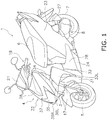
- FIG. 1 is a perspective view of a straddled vehicle 1 according to the preferred embodiment.
- FIG. 2 is a side view of the straddled vehicle 1.
- FIG. 3 is a top view of the straddled vehicle 1.
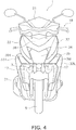
- FIG. 4 is a front view of the straddled vehicle 1.
- the straddled vehicle 1 according to the present preferred embodiment is a scooter-type vehicle.
- the straddled vehicle 1 includes a vehicle body frame 2, a steering device 3, a vehicle body cover 4, a front wheel 5, a seat 6, a rear wheel 7 and a drive unit 8.
- a back-and-forth direction of the straddled vehicle 1, an up-and-down direction of the straddled vehicle 1 and a right-and-left direction of the straddled vehicle 1 refer to a back-and-forth direction, an up-and-down direction and a right-and-left direction seen from a rider on the straddled vehicle 1.
- the back-and-forth direction not only indicates directions arranged in parallel to the back-and-forth direction of the straddled vehicle 1, but also encompasses directions tilting within an angular range of ⁇ 45 degrees with respect to the back-and-forth direction of the straddled vehicle 1. In other words, a given direction closer to the back-and-forth direction than to the right-and-left direction and the up-and-down direction is classified as the back-and-forth direction.
- the up-and-down direction encompasses directions tilting within an angular range of ⁇ 45 degrees with respect to the up-and-down direction of the straddled vehicle 1.
- a given direction closer to the up-and-down direction than to the back-and-forth direction and the right-and-left direction is classified as the up-and-down direction.
- the right-and-left direction encompasses directions tilting within an angular range of ⁇ 45 degrees with respect to the right-and-left direction of the straddled vehicle 1.
- a given direction closer to the right-and-left direction than to the back-and-forth direction and the up-and-down direction is classified as the right-and-left direction.
- the term “vehicle width directionally inward” means directions approaching along the vehicle width direction to an axis that passes through the center of the vehicle in the vehicle width direction and extends in the back-and-forth direction.
- vehicle width directionally outward means directions arranged along the vehicle width direction in opposition to the directions meant by the term “vehicle width directionally inward”.
- vehicle width directionally outward means directions separating from the axis that passes through the center of the vehicle in the vehicle width direction and extends in the back-and-forth direction.
- the vehicle body frame 2 includes a head pipe 11, a down frame 12, a lower frame 13 and a seat frame 14.
- the down frame 12 extends downward from the head pipe 11.
- the lower frame 13 is connected to a lower portion of the down frame 12.
- the lower frame 13 extends backward from the lower portion of the down frame 12.
- the seat frame 14 is connected to the lower frame 13.
- the seat frame 14 extends backward and upward from a rear portion of the lower frame 13.
- the steering device 3 includes a steering shaft 15, a bracket 16 and right and left suspensions 17.
- the steering shaft 15 is inserted into the head pipe 11.
- the steering shaft 15 is supported by the head pipe 11 and is thereby turnable right and left.
- the steering shaft 15 is connected at its lower portion to the right and left suspensions 17 through the bracket 16.
- the suspensions 17 support the front wheel 5 such that the front wheel 5 is rotatable.
- the steering shaft 15 is connected at its upper portion to a handle 18.
- the handle 18 is supported by the upper end portion of the steering shaft 15.
- the vehicle body cover 4 includes a handle cover 21, a front cover assembly 22, a rear cover 23 and a lower cover 24.
- the handle cover 21 covers the front and rear sides of the handle 18.
- a meter panel 25 is attached to the upper surface of the handle cover 21.
- the meter panel 25 includes, for instance, a speed meter.
- the front cover assembly 22 is disposed lower than the handle cover 21.
- the front cover assembly 22 is disposed in front of the head pipe 11.
- the front cover assembly 22 will be explained below in detail.
- the rear cover 23 covers the surroundings of the seat frame 14.
- the rear cover 23 is disposed under the seat 6.
- the seat 6 is disposed backward of the head pipe 11.
- the seat 6 is disposed over the seat frame 14.
- the seat 6 is supported by the seat frame 14.
- the seat 6 is supported by the seat frame 14 through a stay (not shown in the drawings) and a storage (not shown in the drawings). Alternatively, the seat 6 may be directly supported by the seat frame 14.
- the lower cover 24 is disposed between the front cover assembly 22 and the rear cover 23.
- the lower cover 24 covers the surroundings of the lower frame 13.
- the lower cover 24 includes a footboard 28 as portion of its upper surface.
- the footboard 28 is disposed lower than and forward of the seat 6.
- the footboard 28 is disposed over the lower frame 13.
- the footboard 28 is provided for allowing a rider to put his/her feet thereon.
- the footboard 28 has a flat shape. It should be noted that the shape of the footboard 28 is not limited to this.
- the footboard 28 may be shaped such that its vehicle width directional middle portion protrudes in an upwardly convex shape.
- the drive unit 8 is disposed under the seat 6.
- the drive unit 8 is pivotably supported by the vehicle body frame 2.
- the drive unit 8 includes, for instance, an engine and a transmission.
- the drive unit 8 supports the rear wheel 7 such that the rear wheel 7 is rotatable.
- the rear wheel 7 is supported by the vehicle body frame 2 through a rear suspension 27.
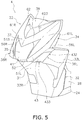
- FIG. 5 is a perspective view of a front portion of the vehicle body cover 4.
- the vehicle body cover 4 includes an inner cover 31 and a leg shield 32.
- the inner cover 31 is disposed under the front cover assembly 22.
- the inner cover 31 is made in a backwardly recessed shape.
- the front wheel 5 is disposed in front of the inner cover 31.
- the leg shield 32 is disposed behind the front cover assembly 22 and the inner cover 31.
- the leg shield 32 extends upward from a front portion of the footboard 28.
- the leg shield 32 covers the head pipe 11 and the down frame 12 from behind.
- the vehicle body cover 4 includes a left side cover 33L and a right side cover 33R.
- the left side cover 33L and the right side cover 33R are members provided separately from the front cover assembly 22.
- the left side cover 33L is disposed leftward of the leg shield 32 and the inner cover 31.
- the right side cover 33R is disposed rightward of the leg shield 32 and the inner cover 31.
- the front cover assembly 22 includes a first cover member 34, a headlight 35, a left flasher light 36L, a right flasher light 36R, a second cover member 37 and an upper cover 38.
- the first cover member 34 is supported by the vehicle body frame 2.
- the first cover member 34 is attached to the leg shield 32.
- the first cover member 34 is made of an opaque material.
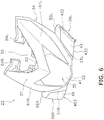
- FIG. 6 is a perspective view of the front cover assembly 22.
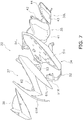
- FIG. 7 is an exploded perspective view of the front cover assembly 22.
- FIG. 8 is a front view of the front cover assembly 22.
- FIG. 9 is a side view of the front cover assembly 22.
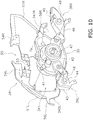
- FIG. 10 is an oblique rear view of the first cover member 34, the headlight 35, the left flasher light 36L and the right flasher light 36R. It should be noted that the upper cover 38 is not illustrated in FIGS. 6 , 8 and 9 .
- the headlight 35 includes a headlight lens 41 and a headlight body 42.
- the headlight lens 41 is attached to headlight body 42.
- the headlight lens 41 is made of a material with translucency.
- a headlight light source 47 is attached to the headlight body 42.
- the headlight light source 47 is a bulb.
- the headlight light source 47 may be an LED.
- the left flasher light 36L includes a left flasher lens 43 and a left flasher body 44.
- the left flasher lens 43 is attached to the left flasher body 44.
- the left flasher lens 43 is made of a material with translucency.
- a left flasher light source 48 is attached to the left flasher body 44.
- the left flasher light source 48 is a bulb.
- the left flasher light source 48 may be an LED.
- the right flasher light 36R includes a right flasher lens 45 and a right flasher body 46.
- the right flasher lens 45 is attached to the right flasher body 46.
- the right flasher lens 45 is made of a material with translucency.
- a right flasher light source 49 is attached to the right flasher body 46.
- the right flasher light source 49 is a bulb.
- the right flasher light source 49 may be an LED.
- the headlight 35, the left flasher light 36L and the right flasher light 36R are attached to the first cover member 34.
- the headlight 35, the left flasher light 36L and the right flasher light 36R are supported by the first cover member 34.
- the headlight lens 41, the left flasher lens 43 and the right flasher lens 45 are provided separately from each other.
- FIG. 11 is a perspective view of the first cover member 34.
- the first cover member 34 includes a middle opening 341, a left cutout 342L, a right cutout 342R and a recess 55.
- the middle opening 341 is located in the right-and-left directional middle of the first cover member 34.
- the left cutout 342L is provided on the left end portion of the first cover member 34.
- the right cutout 342R is provided on the right end portion of the first cover member 34.
- the recess 55 is recessed downward from the upper edge of the first cover member 34.
- the headlight lens 41 is disposed in the middle opening 341.
- the left flasher lens 43 is disposed in the left cutout 342L.
- the right flasher lens 45 is disposed in the right cutout 342R.
- the left flasher lens 43 is disposed leftward of the headlight lens 41.
- the right flasher lens 45 is disposed rightward of the headlight lens 41.
- the upper end of the left flasher lens 43 and that of the right flasher lens 45 are located lower than the upper end of the headlight lens 41, and are simultaneously located higher than the lower end of the headlight lens 41.
- the lower end of the left flasher lens 43 and that of the right flasher lens 45 are located at approximately the same height as the lower end of the headlight lens 41.
- the first cover member 34 includes a first left cover portion 51L, a first right cover portion 51R, a first lower cover portion 52 and a coupling portion 53.
- the first left cover portion 51L is located between the headlight lens 41 and the left flasher lens 43.
- the first right cover portion 51R is located between the headlight lens 41 and the right flasher lens 45.
- the recess 55 is located between the first left cover portion 51L and the first right cover portion 51R. The recess 55 is located over the coupling portion 53.
- the first lower cover portion 52 is located under the headlight lens 41.
- the lower end portion of the first left cover portion 51L and that of the first right cover portion 51R continue to the first lower cover portion 52.
- the coupling portion 53 is located over the headlight lens 41.
- the coupling portion 53 is located between the recess 55 and the middle opening 341. The first left cover portion 51L and the first right cover portion 51R are coupled through the coupling portion 53.
- the first left cover portion 51L includes a first left fixation portion 54L.
- the first left fixation portion 54L is provided on an upper portion of the first left cover portion 51L.
- the first left fixation portion 54L is fixed to the leg shield 32 through a fastener member such as a bolt.
- the first right cover portion 51R includes a first right fixation portion 54R.
- the first right fixation portion 54R is provided on an upper portion of the first right cover portion 51R.
- the first right fixation portion 54R is fixed to the leg shield 32 through a fastener member such as a bolt.
- the first left cover portion 51L extends to a lower position than the lower end of a left edge 411L of the headlight lens 41.
- the headlight lens 41 and the left flasher lens 43 are divided through the first left cover portion 51L.
- the first right cover portion 51R extends to a lower position than the lower end of a right edge 411R of the headlight lens 41.
- the headlight lens 41 and the right flasher lens 45 are divided through the first right cover portion 51R.
- the first cover member 34 includes a left protruding portion 56L and a right protruding portion 56R.
- the left protruding portion 56L protrudes leftward from the first left cover portion 51L.
- the left protruding portion 56L is located over the left flasher lens 43.
- the upper end of the left protruding portion 56L is located lower than that of the headlight lens 41.
- an upper surface 561L of the left protruding portion 56L continues to an upper surface 431 of the left flasher lens 43, and backwardly tilts up.
- the left protruding portion 56L includes a second left fixation portion 562L.
- the left side cover 33L is attached to the second left fixation portion 562L.
- the right protruding portion 56R protrudes rightward from the first right cover portion 51R.
- the right protruding portion 56R is located over the right flasher lens 45.
- the upper end of the right protruding portion 56R is located lower than that of the headlight lens 41.
- the right protruding portion 56R is provided bilaterally symmetric to the left protruding portion 56L. Therefore in the vehicle side view, similarly to the left protruding portion 56L, the upper surface of the right protruding portion 56R continues to that of the right flasher lens 45, and backwardly tilts up.
- the right protruding portion 56R includes a second right fixation portion 562R.
- the right side cover 33R is attached to the second right fixation portion 562R.
- the first cover member 34 does not include a portion located leftward of a left edge 432 of the left flasher lens 43.
- the left edge 432 of the left flasher lens 43 is connected to the left side cover 33L.
- the first cover member 34 does not include a portion located below a lower edge 433 of the left flasher lens 43.
- a right edge 434 of the left flasher lens 43 is connected to the first left cover portion 51L.
- An upper edge 435 of the left flasher lens 43 is connected to the left protruding portion 56L.
- the first cover member 34 does not include a portion located rightward of a right edge 452 of the right flasher lens 45.
- the right edge 452 of the right flasher lens 45 is connected to the right side cover 33R.
- the first cover member 34 does not include a portion located below a lower edge 453 of the right flasher lens 45.
- a left edge 454 of the right flasher lens 45 is connected to the first right cover portion 51R.
- An upper edge 455 of the right flasher lens 45 is connected to the right protruding portion 56R.
- FIG. 12 is a perspective view of the second cover member 37.
- the second cover member 37 is provided separately from the first cover member 34, and is attached to the outer surface of the first cover member 34.
- the second cover member 37 includes a second left cover portion 61L, a second right cover portion 61R and a second middle cover portion 62.
- the second left cover portion 61L overlaps with the first cover member 34 in a region between the headlight lens 41 and the left flasher lens 43.
- the second left cover portion 61L is attached to the first left cover portion 51L and overlaps with portion of the first left cover portion 51L in the vehicle front view.
- the second right cover portion 61R is provided bilaterally symmetric to the second left cover portion 61L. In the vehicle front view, at least portion of the second right cover portion 61R overlaps with the first cover member 34 in a region between the headlight lens 41 and the right flasher lens 45. When described in detail, the second right cover portion 61R is attached to the first right cover portion 51R and overlaps with portion of the first right cover portion 51R in the vehicle front view.
- the second middle cover portion 62 is located between the second left cover portion 61L and the second right cover portion 61R.
- the second middle cover portion 62 couples the second left cover portion 61L and the second right cover portion 61R.
- the second middle cover portion 62 overlaps with a portion located between the recess 55 and the middle opening 341 in the first cover member 34.
- the second middle cover portion 62 overlaps with the coupling portion 53.
- the second left cover portion 61L includes a left inner edge 611L and a left outer edge 612L.
- the left inner edge 611L and the left outer edge 612L compose a boundary between the second left cover portion 61L and the first cover member 34.
- the left inner edge 611L and the left outer edge 612L are located between the headlight lens 41 and the left flasher lens 43.
- the left inner edge 611L extends obliquely upward to the left.
- the left inner edge 611L is disposed away leftward from the left edge 411L of the headlight lens 41. Therefore, in the vehicle front view, portion of the first left cover portion 51L is visible between the left inner edge 611L and the left edge 411L of the headlight lens 41. In the vehicle side view, the left inner edge 611L and the left outer edge 612L extend obliquely upward to the rear.
- An upper portion of the left edge 411L of the headlight lens 41 extends obliquely upward to the right.
- a lower portion of the left edge 411L extends obliquely upward to the left.
- the lower portion of the left edge 411L tilts in the same direction as the left inner edge 611L.
- the left outer edge 612L extends obliquely upward to the left.
- the left outer edge 612L is disposed away from the right edge 434 of the left flasher lens 43. Therefore, in the vehicle front view, portion of the first left cover portion 51L is visible between the left outer edge 612L and the right edge 434 of the left flasher lens 43.
- the left outer edge 612L and the left inner edge 611L continue at a lower end 613L of the second left cover portion 61L.
- the lower end 613L of the second left cover portion 61L is disposed away upward from a lower edge 511L of the first left cover portion 51L. Therefore, in the vehicle front view, portion of the first left cover portion 51L is visible between the lower end 613L of the second left cover portion 61L and the lower edge 511L of the first left cover portion 51L.
- the second right cover portion 61R includes a right inner edge 611R and a right outer edge 612R.
- the right inner edge 611R and the right outer edge 612R compose a boundary between the second right cover portion 61R and the first cover member 34.
- the right inner edge 611R extends obliquely upward to the right.
- the right inner edge 611R is disposed away rightward from the right edge 411R of the headlight lens 41. Therefore, in the vehicle front view, portion of the first right cover portion 51R is visible between the right inner edge 611R and the right edge 411R of the headlight lens 41. In the vehicle side view, the right inner edge 611R and the right outer edge 612R extend obliquely upward to the rear.
- An upper portion of the right edge 411R of the headlight lens 41 extends obliquely upward to the left.
- a lower portion of the right edge 411R extends obliquely upward to the right.
- the lower portion of the right edge 411R tilts in the same direction as the right inner edge 611R.
- the right outer edge 612R extends obliquely upward to the right.
- the right outer edge 612R is disposed away from the left edge 454 of the right flasher lens 45. Therefore, in the vehicle front view, portion of the first right cover portion 51R is visible between the right outer edge 612R and the left edge 454 of the right flasher lens 45.
- the right outer edge 612R and the right inner edge 611R continue at a lower end 613R of the second right cover portion 61R.
- the lower end 613R of the second right cover portion 61R is disposed away upward from a lower edge 511R of the first right cover portion 51R. Therefore, in the vehicle front view, portion of the first right cover portion 51R is visible between the lower end 613R of the second right cover portion 61R and the lower edge 511R of the first right cover portion 51R.
- the lower edge of the second middle cover portion 62 includes a middle left edge 621L and a middle right edge 621R.
- the middle left edge 621L extends obliquely upward to the left.
- the middle left edge 621L adjoins the headlight lens 41 and the first left cover portion 51L.
- the middle left edge 621L continues to the left inner edge 611L.
- portion of the first left cover portion 51L is visible in a region enclosed by the middle left edge 621L, the left inner edge 611L and the upper portion of the left edge 411L.
- the middle left edge 621L and the middle right edge 621R continues at a lower end 622 of the lower edge of the second middle cover portion 62.
- the lower end 622 of the lower edge of the second middle cover portion 62 is located higher than the upper ends of the right and left flasher lens 44 and 43.
- the middle right edge 621R extends obliquely upward to the right.
- the middle right edge 621R adjoins the headlight lens 41 and the first right cover portion 51R.
- the middle right edge 621R continues to the right inner edge 611R.
- portion of the first right cover portion 51R is visible in a region enclosed by the middle right edge 621R, the right inner edge 611R and the upper portion of the right edge 411R.
- An upper edge 623 of the second middle cover portion 62 has a downwardly recessed shape. In the vehicle front view, the upper edge 623 of the second middle cover portion 62 overlaps with the recess 55 of the first cover member 34.
- the upper cover 38 shown in FIG. 5 is attached to the upper edge 623 of the second middle cover portion 62.
- the upper cover 38 is provided separately from the first cover member 34.
- the upper cover 38 is disposed in the recess 55.
- the upper cover 38 covers the internal space of the first cover member 34 from above.
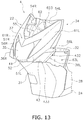
- FIG. 13 is a perspective view of the front portion of the vehicle body cover 4 from which the upper cover 38 and the right and left side covers 33R and 33L are detached.
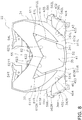
- FIG. 14 is a top view of the front portion of the vehicle body cover 4 from which the upper cover 38 and the right and left side covers 33R and 33L are detached.
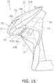
- FIG. 15 is a left side view of the front portion of the vehicle body cover 4 from which the upper cover 38 and the right and left side covers 33R and 33L are detached.
- a battery 29 is disposed between the front cover assembly 22 and the head pipe 11. In the vehicle top view, the battery 29 is disposed behind the headlight 35.
- the upper cover 38 is detached from the vehicle body cover 4
- at least portion of the battery 29 is visible in the vehicle top view.
- at least portion of the headlight body 42 is visible in the vehicle top view.
- the left flasher light 36L, the leg shield 32 and the inner cover 31 form a left opening 63L opened leftward.
- the left opening 63L is disposed behind the left flasher light 36L. At least portion of the left flasher body 44 is visible through the left opening 63L. At least portion of the head pipe 11 is visible through the left opening 63L.
- the left side cover 33L is disposed on the left opening 63L. The left edge 432 of the left flasher lens 43 is directly attached to the left side cover 33L. The left opening 63L is covered with the left side cover 33L.
- FIG. 16 is a right side view of the front portion of the vehicle body cover 4 from which the upper cover 38 and the right and left side covers 33R and 33L are detached.
- the right flasher light 36R, the leg shield 32 and the inner cover 31 form a right opening 63R opened rightward.
- the right opening 63R is disposed behind the right flasher light 36R.
- At least portion of the right flasher body 46 is visible through the right opening 63R.
- At least portion of the head pipe 11 is visible through the right opening 63R.
- the right side cover 33R is disposed on the right opening 63R.
- the right edge 452 of the right flasher lens 45 is directly attached to the right side cover 33R.
- the right opening 63R is covered with the right side cover 33R.
- the headlight 35 and the right and left flasher lights 36R and 36L are supported by the first cover member 34. Therefore, the right and left side covers 33R and 33L are not required to be provided with openings for attaching the right and left flasher lights 36R and 36L. Accordingly, degradation in stiffnesses of the right and left side covers 33R and 33L can be inhibited.
- the first cover member 34 is provided as an integrated member of covers requiring stiffnesses to support the headlight 35 and the right and left flasher lights 36R and 36L. Hence, stiffnesses required for the right and left side covers 33R and 33L can be lowered. Accordingly, deficiency in stiffnesses of the right and left side covers 33R and 33L can be inhibited.
- the right and left side covers 33R and 33L are not required to support heavy objects. Hence, it is possible to lower stiffness required for the coupling portion 53 at which the first right and left cover portions 51R and 51L of the first cover member 34, to which the right and left side covers 33R and 33L are respectively attached, are coupled. Accordingly, deficiency in stiffness of the coupling portion 53 can be inhibited.
- the headlight lens 41 and the left flasher lens 43 are divided through the first left cover portion 51L. Therefore, visibility of the left flasher lens 43 can be enhanced.
- the headlight lens 41 and the right flasher lens 45 are divided through the first right cover portion 51R. Therefore, visibility of the right flasher lens 45 can be enhanced.
- the second left cover portion 61L overlaps with the first left cover portion 51L in a region between the headlight lens 41 and the left flasher lens 43.
- the second right cover portion 61R overlaps with the first right cover portion 51R in a region between the headlight lens 41 and the right flasher lens 45. Therefore, degradation in stiffnesses of the first right and left cover portions 51R and 51L can be enhanced even when visibility of the right flasher light 36R and that of the left flasher light 36L are respectively enhanced by increasing the width of the first right cover portion 51R and that of the first left cover portion 51L.
- the right and left flasher lights 36R and 36L are supported by the first cover member 34. Hence, the right and left side covers 33R and 33L can be detached without detaching the right and left flasher lights 36R and 36L. Accordingly, maintenance performance can be enhanced.
- the left flasher light 36L composes portion of the left opening 63L
- the right flasher light 36R composes portion of the right opening 63R. Therefore, the left flasher light 36L is easily accessible through the left opening 63L, whereas the right flasher light 36R is easily accessible through the right opening 63R. Accordingly, maintenance performance of the right and left flasher lights 36R and 36L can be enhanced.
- replacement of components of the left flasher light 36L can be easily done by accessing the left flasher light 36L through the left opening 63L. This is also true of the right flasher light 36R.
- Portion of the right opening 63R is formed by the right flasher light 36R, whereas portion of the left opening 63L is formed by the left flasher light 36L. Therefore, the left side cover 33L is directly connected to the left flasher light 36L, and any other component is not provided between the left side cover 33L and the left flasher light 36L. Likewise, any other component is not provided between the right side cover 33R and the right flasher light 36R. Therefore, width directional increase in the front cover assembly 22 can be inhibited.
- the first cover member 34 does not include a portion located under the lower edge 433 of the left flasher lens 43. In the vehicle front view, the first cover member 34 does not include a portion located under the lower edge 453 of the right flasher lens 45. Therefore, the first cover member 34 can be formed with a smaller size and the stiffness of the first cover member 34 can be more enhanced in comparison with a construction that the first cover member 34 includes a portion located under the lower edge 433 of the left flasher lens 43 and a portion located under the lower edge 453 of the right flasher lens 45.
- the first cover member 34 includes the recess 55 downwardly recessed from the upper edge of the first cover member 34. Therefore, the interior of the front cover assembly 22 is accessible through the recess 55 by detaching the upper cover 38. Accordingly, maintenance performance can be enhanced. For example, maintenance of the battery 29 can be easily done through the recess 55. Additionally, adjustment of the optical axis of the headlight 35 can be easily done by accessing the headlight 35 through the recess 55. Alternatively, replacement of the components of the headlight 35 can be easily done.
- the second middle cover portion 62 overlaps with a portion located between the recess 55 and the middle opening 341 in the first cover member 34. Therefore, even when the first cover member 34 is provided with the recess 55, degradation in stiffness of the first cover member 34 can be inhibited.
- the boundary between the second left cover portion 61L and the first cover member 34 is located between the headlight lens 41 and the left flasher lens 43.
- the boundary between the second right cover portion 61R and the first cover member 34 is located between the headlight lens 41 and the right flasher lens 45. Therefore, an uneven shape is formed between the first cover member 34 and the second left cover portion 61L. Likewise, an uneven shape is formed between the first cover member 34 and the second right cover portion 61R. Accordingly, the stiffness of the front cover assembly 22 can be further enhanced.
- the left flasher lens 43, the right flasher lens 45 and the headlight lens 41 are separately provided. Therefore, attachment/detachment works can be separately performed for the left flasher lens 43, the right flasher lens 45 and the headlight lens 41. Hence, maintenance performance can be enhanced.
- the lower end portion of the first left cover portion 51L and that of the first right cover portion 51R continue to the first lower cover portion 52. Therefore, the stiffness of the first cover member 34 can be more enhanced than that in a construction that the first left cover portion 51L and the first right cover portion 51R do not continue to the first lower cover portion 52.
- the term “straddled vehicle” encompasses a motorcycle, an all-terrain vehicle and a snowmobile.
- the term “motorcycle” is not limited to the scooter-type vehicle according to the aforementioned preferred embodiment, and may encompasses other types of vehicle such as a moped.
- the number of the front wheels is not limited to one, and alternatively, may be two or greater.
- the number of the rear wheels is not limited to one, and alternatively, may be two or greater.
- the construction of the front cover assembly 22 may be changed from that described in the aforementioned preferred embodiment.
- only portion of the second left cover portion 61L may overlap with the first cover member 34 in the region between the headlight lens 41 and the left flasher lens 43.
- only portion of the second right cover portion 61R may overlap with the first cover member 34 in the region between the headlight lens 41 and the right flasher lens 45.
- the constituent members of the left opening 63L are not limited to only the left flasher light 36L, the leg shield 32 and the inner cover 31, and may additionally include another member.
- the constituent members of the right opening 63R are not limited to only the right flasher light 36R, the leg shield 32 and the inner cover 31, and may additionally include another member.
- the first cover member 34 may not be provided with the recess 55.
- the upper cover 38 may be integrated with the first cover member 34 or the second cover member 37. As shown in FIG. 17 , the upper cover 38 may include a mounter 69 for a license plate LP.
- the shape or positional arrangement of the first cover member 34 may be changed.
- the shape or positional arrangement of the second cover member 37 may be changed.
- the shapes or positional arrangements of the right and left side covers 33R and 33L may be changed.
- the component disposed inside the front cover assembly 22 is not limited to the battery 29, and may be another component.
- the construction of the headlight 35 or the constructions of the right and left flasher lights 36R and 36L may be changed.
- the left flasher lens 43, the right flasher lens 45 and the headlight lens 41 are not limited to components separately provided, and may be provided as an integrated component.
Landscapes
- Engineering & Computer Science (AREA)
- Mechanical Engineering (AREA)
- Non-Portable Lighting Devices Or Systems Thereof (AREA)
Claims (14)
- Spreizsitz-Fahrzeug (1), das umfasst:einen Fahrzeug-Karosserierahmen (2), der ein Steuerrohr (11) enthält;eine Frontverkleidungs-Anordnung (22), die vor dem Steuerrohr (11) angeordnet ist;eine Innenverkleidung (31), die unter der Frontverkleidungs-Anordnung (22) angeordnet ist;einen Beinschutz (32), der hinter der Frontverkleidungs-Anordnung (22) und der Innenverkleidung (31) angeordnet ist;eine linke Seitenverkleidung (33L), die separat von der Frontverkleidungs-Anordnung (22) vorhanden ist; sowieeine rechte Seitenverkleidung (33R), die separat von der Frontverkleidungs-Anordnung (22) vorhanden ist; wobeidie Frontverkleidungs-Anordnung (22) enthält:ein erstes Verkleidungs-Element (34), das von dem Fahrzeug-Karosserierahmen (2) getragen wird, wobei das erste Verkleidungs-Element (34) eine mittlere Öffnung (341) enthält, die, in einer Fahrzeug-Vorderansicht in einer Mitte in der Querrichtung angeordnet ist,einen Scheinwerfer (35), der von dem ersten Verkleidungs-Element (34) getragen wird, wobei der Scheinwerfer (35) eine Scheinwerfer-Linse (41) enthält, die in der mittleren Öffnung (341) angeordnet ist,ein linkes Blinklicht (36L), das von dem ersten Verkleidungs-Element (34) getragen wird, wobei das linke Blinklicht (36L) eine linke Blinklicht-Linse (43) enthält,ein rechtes Blinklicht (36R), das von dem ersten Verkleidungs-Element (34) getragen wird, wobei das rechte Blinklicht (36R) eine rechte Blinklicht-Linse (43) enthält, sowieein zweites Verkleidungs-Element (37), das separat von dem ersten Verkleidungs-Element (34) vorhanden ist, wobei das zweite Verkleidungs-Element (37) an einer Außenfläche des ersten Verkleidungs-Elementes (34) angebracht ist, unddas zweite Verkleidungs-Element (37) enthält:einen zweiten linken Verkleidungs-Abschnitt (61L), der sich in einem Bereich zwischen der Scheinwerfer-Linse (41) und der linken Blinklicht-Linse (43), in der Fahrzeug-Vorderansicht, wenigstens teilweise mit dem ersten Verkleidungs-Element (34) überlappt, sowieeinen zweiten rechten Verkleidungs-Abschnitt (61R), der sich in einem Bereich zwischen der Scheinwerfer-Linse (41) und der rechten Blinklicht-Linse (43) in der Fahrzeug-Vorderansicht wenigstens teilweise mit dem ersten Verkleidungs-Element (34) überlappt,dadurch gekennzeichnet, dassdas linke Blinklicht (36L), in der Fahrzeug-Vorderansicht, links von der Scheinwerfer-Linse (41) und an einem linken Endabschnitt des ersten Verkleidungs-Elementes (34) angeordnet ist,das rechte Blinklicht (36R), in der Fahrzeug-Vorderansicht, rechts von der Scheinwerfer-Linse (41) und an einem rechten Endabschnitt des ersten Verkleidungs-Elementes (34) angeordnet ist,ein oberes Ende der linken Blinklicht-Linse (43) und ein oberes Ende der rechten Blinklicht-Linse (43), in der Fahrzeug-Vorderansicht, tiefer angeordnet sind als ein oberes Ende der Scheinwerfer-Linse (41) und höher als ein unteres Ende der Scheinwerfer-Linse (41),wenigstens das linke Blinklicht (36L), der Beinschutz (32) und die Innenverkleidung (31) eine linke Öffnung (63L) bilden, die nach links geöffnet ist,wenigstens das rechte Blinklicht (36R), der Beinschutz (32) und die Innenverkleidung (31) eine rechte Öffnung (63R) bilden, die nach rechts geöffnet ist,die linke Seitenverkleidung (33L) an der linken Öffnung (63L) angeordnet ist, unddie rechte Seitenverkleidung (33R) an der rechten Öffnung (63R) angeordnet ist.
- Spreizsitz-Fahrzeug (1) nach Anspruch 1, wobei
das erste Verkleidungs-Element (34) eine Vertiefung (55) enthält, die von einer Oberkante des ersten Verkleidungs-Elementes (34) nach unten vertieft ist, und
das zweite Verkleidungs-Element (37) einen zweiten mittleren Verkleidungs-Abschnitt (62) enthält, wobei sich der zweite mittlere Verkleidungs-Abschnitt (62), in der Fahrzeug-Vorderansicht mit wenigstens einem Abschnitt überlappt, der sich zwischen der Vertiefung (55) und der mittleren Öffnung (341) in dem ersten Verkleidungs-Element (34) befindet. - Spreizsitz-Fahrzeug (1) nach Anspruch 2, wobei:die Frontverkleidungs-Anordnung (22) eine obere Verkleidung (38) enthält,die obere Verkleidung (38) separat von dem ersten Verkleidungs-Element (34) und dem zweiten Verkleidungs-Element (37) vorhanden ist und die obere Verkleidung (38) so angeordnet ist, dass sie die Vertiefung (55) abdeckt.
- Spreizsitz-Fahrzeug (1) nach Anspruch 3, wobei die obere Verkleidung (38) eine Anbringung (69) für ein Nummernschild (LP) enthält.
- Spreizsitz-Fahrzeug (1) nach einem der Ansprüche 1 bis 4, wobei
eine Grenze zwischen dem zweiten linken Verkleidungs-Abschnitt (61L) und dem ersten Verkleidungs-Element (34), in der Fahrzeug-Vorderansicht, sich zwischen der Scheinwerfer-Linse (41) und der linken Blinklicht-Linse (43) befindet, und
eine Grenze zwischen dem zweiten rechten Verkleidungs-Abschnitt (61R) und dem ersten Verkleidungs-Element (34), in der Fahrzeug-Vorderansicht, sich zwischen der Scheinwerfer-Linse (41) und der rechten Blinklicht-Linse (43) befindet. - Spreizsitz-Fahrzeug (1) nach einem der Ansprüche 1 bis 5, wobei
das erste Verkleidungs-Element (34), in der Fahrzeug-Vorderansicht, zwischen dem zweiten linken Verkleidungs-Abschnitt (61L) und der Scheinwerfer-Linse (41) teilweise sichtbar ist, und
das erste Verkleidungs-Element (34), in der Fahrzeug-Vorderansicht, zwischen dem zweiten rechten Verkleidungs-Abschnitt (61R) und der Scheinwerfer-Linse (41) teilweise sichtbar ist. - Spreizsitz-Fahrzeug (1) nach einem der Ansprüche 1 bis 6, wobei
das erste Verkleidungs-Element (34), in der Fahrzeug-Vorderansicht, zwischen dem zweiten linken Verkleidungs-Abschnitt (61L) und der linken Blinklicht-Linse (43) teilweise sichtbar ist, und
das erste Verkleidungs-Element (34), in der Fahrzeug-Vorderansicht, zwischen dem zweiten rechten Verkleidungs-Abschnitt (61R) und der rechten Blinklicht-Linse (43) teilweise sichtbar ist. - Spreizsitz-Fahrzeug (1) nach einem der Ansprüche 1 bis 7, wobei
die Grenze zwischen dem zweiten linken Verkleidungs-Abschnitt (61L) und dem ersten Verkleidungs-Element (34), in einer Fahrzeug-Seitenansicht, schräg nach oben verläuft, und
die Grenze zwischen dem zweiten rechten Verkleidungs-Abschnitt (61R) und dem ersten Verkleidungs-Element (34), in der Fahrzeug-Seitenansicht, schräg nach oben verläuft. - Spreizsitz-Fahrzeug (1) nach einem der Ansprüche 1 bis 8, das des Weiteren umfasst:
eine Batterie (29), die zwischen der Frontverkleidungs-Anordnung (22) und dem Steuerrohr (11) angeordnet ist. - Spreizsitz-Fahrzeug nach einem der Ansprüche 1 bis 9, wobei die linke Blinklicht-Linse (43), die rechte Blinklicht-Linse (43) und die Scheinwerfer-Linse (41) separat voneinander vorhanden sind.
- Spreizsitz-Fahrzeug (1) nach einem der Ansprüche 1 bis 10, wobei
das erste Verkleidungs-Element (34) enthält:einen ersten linken Verkleidungs-Abschnitt (51L), der, in der Fahrzeug-Vorderansicht, sich zwischen der Scheinwerfer-Linse (41) und der linken Blinklicht-Linse (43) befindet,einen ersten rechten Verkleidungs-Abschnitt (51R), der, in der Fahrzeug-Vorderansicht, sich zwischen der Scheinwerfer-Linse (41) und der rechten Blinklicht-Linse (43) befindet, sowieeinen ersten unteren Verkleidungs-Abschnitt (52), der, in der Fahrzeug-Vorderansicht, sich unter der Scheinwerfer-Linse (41) befindet, undein unterer Endabschnitt des ersten linken Verkleidungs-Abschnitts (51L) und ein unterer Endabschnitt des ersten rechten Verkleidungs-Abschnitts (51R) sich an den ersten unteren Verkleidungs-Abschnitt (52) anschließen. - Spreizsitz-Fahrzeug (1) nach einem der Ansprüche 1 bis 11, wobei
das erste Verkleidungs-Element (34) keinen Abschnitt enthält, der, in der Fahrzeug-Vorderansicht, sich links von einer linken Kante der linken Blinklicht-Linse (43) befindet, und
das erste Verkleidungs-Element (34) keinen Abschnitt enthält, der, in der Fahrzeug-Vorderansicht, sich rechts von einer rechten Kante der rechten Blinklicht-Linse (43) befindet. - Spreizsitz-Fahrzeug (1) nach einem der Ansprüche 1 bis 11, wobei
die linke Kante der linken Blinklicht-Linse (43) direkt an der linken Seitenverkleidung (33L) angebracht ist, und
die rechte Kante der rechten Blinklicht-Linse (43) direkt an der rechten Seitenverkleidung (33R) angebracht ist. - Spreizsitz-Fahrzeug (1) nach einem der Ansprüche 1 bis 13, wobei
das erste Verkleidungs-Element (34) keinen Abschnitt enthält, der, in der Fahrzeug-Vorderansicht, sich unter einer Unterkante der linken Blinklicht-Linse (43) befindet, und
das erste Verkleidungs-Element (34) keinen Abschnitt enthält, der, in der Fahrzeug-Vorderansicht, sich unter einer Unterkante der rechten Blinklicht-Linse (43) befindet.
Applications Claiming Priority (1)
| Application Number | Priority Date | Filing Date | Title |
|---|---|---|---|
| JP2016016308A JP2017132436A (ja) | 2016-01-29 | 2016-01-29 | 鞍乗型車両 |
Publications (2)
| Publication Number | Publication Date |
|---|---|
| EP3199437A1 EP3199437A1 (de) | 2017-08-02 |
| EP3199437B1 true EP3199437B1 (de) | 2018-12-12 |
Family
ID=57083194
Family Applications (1)
| Application Number | Title | Priority Date | Filing Date |
|---|---|---|---|
| EP16192329.7A Active EP3199437B1 (de) | 2016-01-29 | 2016-10-05 | Grätschsitzfahrzeug |
Country Status (2)
| Country | Link |
|---|---|
| EP (1) | EP3199437B1 (de) |
| JP (1) | JP2017132436A (de) |
Families Citing this family (6)
| Publication number | Priority date | Publication date | Assignee | Title |
|---|---|---|---|---|
| TWI708700B (zh) * | 2018-10-12 | 2020-11-01 | 日商山葉發動機股份有限公司 | 跨坐型車輛 |
| CN113525566B (zh) * | 2020-04-21 | 2022-06-07 | 雅马哈发动机株式会社 | 骑乘型车辆 |
| JP2021172164A (ja) | 2020-04-21 | 2021-11-01 | ヤマハ発動機株式会社 | 鞍乗型車両 |
| WO2022163249A1 (ja) * | 2021-01-28 | 2022-08-04 | 本田技研工業株式会社 | 鞍乗り型車両 |
| CN115195915B (zh) * | 2021-04-14 | 2023-08-22 | 雅马哈发动机株式会社 | 跨乘式车辆 |
| JP7376558B2 (ja) * | 2021-11-24 | 2023-11-08 | 本田技研工業株式会社 | 鞍乗り型車両 |
Family Cites Families (2)
| Publication number | Priority date | Publication date | Assignee | Title |
|---|---|---|---|---|
| JP2011079337A (ja) * | 2008-01-18 | 2011-04-21 | Yamaha Motor Co Ltd | 車体カバーおよび鞍乗型車両 |
| JP2016020181A (ja) * | 2014-07-15 | 2016-02-04 | ヤマハ発動機株式会社 | 鞍乗型車両 |
-
2016
- 2016-01-29 JP JP2016016308A patent/JP2017132436A/ja active Pending
- 2016-10-05 EP EP16192329.7A patent/EP3199437B1/de active Active
Non-Patent Citations (1)
| Title |
|---|
| None * |
Also Published As
| Publication number | Publication date |
|---|---|
| EP3199437A1 (de) | 2017-08-02 |
| JP2017132436A (ja) | 2017-08-03 |
Similar Documents
| Publication | Publication Date | Title |
|---|---|---|
| EP3199437B1 (de) | Grätschsitzfahrzeug | |
| EP2336012B1 (de) | Vorderer Karosserieaufbau eines Sattelfahrzeugs | |
| US7815353B2 (en) | Headlight device and vehicle | |
| EP3000699B1 (de) | Sattelfahrzeug | |
| JP2006182124A (ja) | 自動二輪車 | |
| EP2163464B1 (de) | Grätschsitz-Fahrzeug | |
| CN110450892B (zh) | 自动二轮车 | |
| EP2208663B1 (de) | Grätschsitz-fahrzeug | |
| EP2610153B1 (de) | Sattelfahrzeug | |
| JP7141299B2 (ja) | 鞍乗型車両 | |
| JP4762629B2 (ja) | 自動二輪車のランプユニット | |
| EP3495252A1 (de) | Sattelfahrzeug | |
| EP3363725B1 (de) | Grätschsitzfahrzeug | |
| EP3199435B1 (de) | Grätschsitzfahrzeug | |
| CN104554536A (zh) | 跨乘式车辆 | |
| US20220250702A1 (en) | Front fairing for a scooter | |
| EP2759461B1 (de) | Gabelschutzstruktur für ein Motorrad | |
| TWI652194B (zh) | Straddle type vehicle | |
| JP7661387B2 (ja) | 鞍乗り型車両のカウル構造 | |
| JP7342063B2 (ja) | ヘッドライトユニット及び傾斜車両 | |
| EP2818390B1 (de) | Sattelfahrzeug | |
| EP3636532A1 (de) | Grätschsitzfahrzeug | |
| JP2019218009A (ja) | 車両 | |
| CN109305263B (zh) | 骑乘型车辆 | |
| JP2018058469A (ja) | 鞍乗型車両 |
Legal Events
| Date | Code | Title | Description |
|---|---|---|---|
| PUAI | Public reference made under article 153(3) epc to a published international application that has entered the european phase |
Free format text: ORIGINAL CODE: 0009012 |
|
| STAA | Information on the status of an ep patent application or granted ep patent |
Free format text: STATUS: REQUEST FOR EXAMINATION WAS MADE |
|
| 17P | Request for examination filed |
Effective date: 20161005 |
|
| AK | Designated contracting states |
Kind code of ref document: A1 Designated state(s): AL AT BE BG CH CY CZ DE DK EE ES FI FR GB GR HR HU IE IS IT LI LT LU LV MC MK MT NL NO PL PT RO RS SE SI SK SM TR |
|
| AX | Request for extension of the european patent |
Extension state: BA ME |
|
| RBV | Designated contracting states (corrected) |
Designated state(s): AL AT BE BG CH CY CZ DE DK EE ES FI FR GB GR HR HU IE IS IT LI LT LU LV MC MK MT NL NO PL PT RO RS SE SI SK SM TR |
|
| GRAP | Despatch of communication of intention to grant a patent |
Free format text: ORIGINAL CODE: EPIDOSNIGR1 |
|
| STAA | Information on the status of an ep patent application or granted ep patent |
Free format text: STATUS: GRANT OF PATENT IS INTENDED |
|
| INTG | Intention to grant announced |
Effective date: 20180613 |
|
| GRAS | Grant fee paid |
Free format text: ORIGINAL CODE: EPIDOSNIGR3 |
|
| GRAA | (expected) grant |
Free format text: ORIGINAL CODE: 0009210 |
|
| STAA | Information on the status of an ep patent application or granted ep patent |
Free format text: STATUS: THE PATENT HAS BEEN GRANTED |
|
| AK | Designated contracting states |
Kind code of ref document: B1 Designated state(s): AL AT BE BG CH CY CZ DE DK EE ES FI FR GB GR HR HU IE IS IT LI LT LU LV MC MK MT NL NO PL PT RO RS SE SI SK SM TR |
|
| REG | Reference to a national code |
Ref country code: GB Ref legal event code: FG4D |
|
| REG | Reference to a national code |
Ref country code: CH Ref legal event code: EP |
|
| REG | Reference to a national code |
Ref country code: AT Ref legal event code: REF Ref document number: 1075595 Country of ref document: AT Kind code of ref document: T Effective date: 20181215 |
|
| REG | Reference to a national code |
Ref country code: DE Ref legal event code: R096 Ref document number: 602016008075 Country of ref document: DE |
|
| REG | Reference to a national code |
Ref country code: IE Ref legal event code: FG4D |
|
| REG | Reference to a national code |
Ref country code: NL Ref legal event code: MP Effective date: 20181212 |
|
| REG | Reference to a national code |
Ref country code: LT Ref legal event code: MG4D |
|
| PG25 | Lapsed in a contracting state [announced via postgrant information from national office to epo] |
Ref country code: HR Free format text: LAPSE BECAUSE OF FAILURE TO SUBMIT A TRANSLATION OF THE DESCRIPTION OR TO PAY THE FEE WITHIN THE PRESCRIBED TIME-LIMIT Effective date: 20181212 Ref country code: LT Free format text: LAPSE BECAUSE OF FAILURE TO SUBMIT A TRANSLATION OF THE DESCRIPTION OR TO PAY THE FEE WITHIN THE PRESCRIBED TIME-LIMIT Effective date: 20181212 Ref country code: BG Free format text: LAPSE BECAUSE OF FAILURE TO SUBMIT A TRANSLATION OF THE DESCRIPTION OR TO PAY THE FEE WITHIN THE PRESCRIBED TIME-LIMIT Effective date: 20190312 Ref country code: FI Free format text: LAPSE BECAUSE OF FAILURE TO SUBMIT A TRANSLATION OF THE DESCRIPTION OR TO PAY THE FEE WITHIN THE PRESCRIBED TIME-LIMIT Effective date: 20181212 Ref country code: LV Free format text: LAPSE BECAUSE OF FAILURE TO SUBMIT A TRANSLATION OF THE DESCRIPTION OR TO PAY THE FEE WITHIN THE PRESCRIBED TIME-LIMIT Effective date: 20181212 Ref country code: ES Free format text: LAPSE BECAUSE OF FAILURE TO SUBMIT A TRANSLATION OF THE DESCRIPTION OR TO PAY THE FEE WITHIN THE PRESCRIBED TIME-LIMIT Effective date: 20181212 Ref country code: NO Free format text: LAPSE BECAUSE OF FAILURE TO SUBMIT A TRANSLATION OF THE DESCRIPTION OR TO PAY THE FEE WITHIN THE PRESCRIBED TIME-LIMIT Effective date: 20190312 |
|
| REG | Reference to a national code |
Ref country code: AT Ref legal event code: MK05 Ref document number: 1075595 Country of ref document: AT Kind code of ref document: T Effective date: 20181212 |
|
| PG25 | Lapsed in a contracting state [announced via postgrant information from national office to epo] |
Ref country code: GR Free format text: LAPSE BECAUSE OF FAILURE TO SUBMIT A TRANSLATION OF THE DESCRIPTION OR TO PAY THE FEE WITHIN THE PRESCRIBED TIME-LIMIT Effective date: 20190313 Ref country code: RS Free format text: LAPSE BECAUSE OF FAILURE TO SUBMIT A TRANSLATION OF THE DESCRIPTION OR TO PAY THE FEE WITHIN THE PRESCRIBED TIME-LIMIT Effective date: 20181212 Ref country code: SE Free format text: LAPSE BECAUSE OF FAILURE TO SUBMIT A TRANSLATION OF THE DESCRIPTION OR TO PAY THE FEE WITHIN THE PRESCRIBED TIME-LIMIT Effective date: 20181212 Ref country code: AL Free format text: LAPSE BECAUSE OF FAILURE TO SUBMIT A TRANSLATION OF THE DESCRIPTION OR TO PAY THE FEE WITHIN THE PRESCRIBED TIME-LIMIT Effective date: 20181212 |
|
| PG25 | Lapsed in a contracting state [announced via postgrant information from national office to epo] |
Ref country code: NL Free format text: LAPSE BECAUSE OF FAILURE TO SUBMIT A TRANSLATION OF THE DESCRIPTION OR TO PAY THE FEE WITHIN THE PRESCRIBED TIME-LIMIT Effective date: 20181212 |
|
| PG25 | Lapsed in a contracting state [announced via postgrant information from national office to epo] |
Ref country code: PL Free format text: LAPSE BECAUSE OF FAILURE TO SUBMIT A TRANSLATION OF THE DESCRIPTION OR TO PAY THE FEE WITHIN THE PRESCRIBED TIME-LIMIT Effective date: 20181212 Ref country code: CZ Free format text: LAPSE BECAUSE OF FAILURE TO SUBMIT A TRANSLATION OF THE DESCRIPTION OR TO PAY THE FEE WITHIN THE PRESCRIBED TIME-LIMIT Effective date: 20181212 Ref country code: PT Free format text: LAPSE BECAUSE OF FAILURE TO SUBMIT A TRANSLATION OF THE DESCRIPTION OR TO PAY THE FEE WITHIN THE PRESCRIBED TIME-LIMIT Effective date: 20190412 |
|
| PG25 | Lapsed in a contracting state [announced via postgrant information from national office to epo] |
Ref country code: SK Free format text: LAPSE BECAUSE OF FAILURE TO SUBMIT A TRANSLATION OF THE DESCRIPTION OR TO PAY THE FEE WITHIN THE PRESCRIBED TIME-LIMIT Effective date: 20181212 Ref country code: SM Free format text: LAPSE BECAUSE OF FAILURE TO SUBMIT A TRANSLATION OF THE DESCRIPTION OR TO PAY THE FEE WITHIN THE PRESCRIBED TIME-LIMIT Effective date: 20181212 Ref country code: EE Free format text: LAPSE BECAUSE OF FAILURE TO SUBMIT A TRANSLATION OF THE DESCRIPTION OR TO PAY THE FEE WITHIN THE PRESCRIBED TIME-LIMIT Effective date: 20181212 Ref country code: RO Free format text: LAPSE BECAUSE OF FAILURE TO SUBMIT A TRANSLATION OF THE DESCRIPTION OR TO PAY THE FEE WITHIN THE PRESCRIBED TIME-LIMIT Effective date: 20181212 Ref country code: IS Free format text: LAPSE BECAUSE OF FAILURE TO SUBMIT A TRANSLATION OF THE DESCRIPTION OR TO PAY THE FEE WITHIN THE PRESCRIBED TIME-LIMIT Effective date: 20190412 |
|
| REG | Reference to a national code |
Ref country code: DE Ref legal event code: R097 Ref document number: 602016008075 Country of ref document: DE |
|
| PLBE | No opposition filed within time limit |
Free format text: ORIGINAL CODE: 0009261 |
|
| STAA | Information on the status of an ep patent application or granted ep patent |
Free format text: STATUS: NO OPPOSITION FILED WITHIN TIME LIMIT |
|
| PG25 | Lapsed in a contracting state [announced via postgrant information from national office to epo] |
Ref country code: SI Free format text: LAPSE BECAUSE OF FAILURE TO SUBMIT A TRANSLATION OF THE DESCRIPTION OR TO PAY THE FEE WITHIN THE PRESCRIBED TIME-LIMIT Effective date: 20181212 Ref country code: DK Free format text: LAPSE BECAUSE OF FAILURE TO SUBMIT A TRANSLATION OF THE DESCRIPTION OR TO PAY THE FEE WITHIN THE PRESCRIBED TIME-LIMIT Effective date: 20181212 Ref country code: AT Free format text: LAPSE BECAUSE OF FAILURE TO SUBMIT A TRANSLATION OF THE DESCRIPTION OR TO PAY THE FEE WITHIN THE PRESCRIBED TIME-LIMIT Effective date: 20181212 |
|
| 26N | No opposition filed |
Effective date: 20190913 |
|
| PG25 | Lapsed in a contracting state [announced via postgrant information from national office to epo] |
Ref country code: TR Free format text: LAPSE BECAUSE OF FAILURE TO SUBMIT A TRANSLATION OF THE DESCRIPTION OR TO PAY THE FEE WITHIN THE PRESCRIBED TIME-LIMIT Effective date: 20181212 |
|
| PG25 | Lapsed in a contracting state [announced via postgrant information from national office to epo] |
Ref country code: MC Free format text: LAPSE BECAUSE OF FAILURE TO SUBMIT A TRANSLATION OF THE DESCRIPTION OR TO PAY THE FEE WITHIN THE PRESCRIBED TIME-LIMIT Effective date: 20181212 |
|
| REG | Reference to a national code |
Ref country code: CH Ref legal event code: PL |
|
| PG25 | Lapsed in a contracting state [announced via postgrant information from national office to epo] |
Ref country code: LU Free format text: LAPSE BECAUSE OF NON-PAYMENT OF DUE FEES Effective date: 20191005 Ref country code: CH Free format text: LAPSE BECAUSE OF NON-PAYMENT OF DUE FEES Effective date: 20191031 Ref country code: LI Free format text: LAPSE BECAUSE OF NON-PAYMENT OF DUE FEES Effective date: 20191031 |
|
| REG | Reference to a national code |
Ref country code: BE Ref legal event code: MM Effective date: 20191031 |
|
| PG25 | Lapsed in a contracting state [announced via postgrant information from national office to epo] |
Ref country code: BE Free format text: LAPSE BECAUSE OF NON-PAYMENT OF DUE FEES Effective date: 20191031 |
|
| PG25 | Lapsed in a contracting state [announced via postgrant information from national office to epo] |
Ref country code: IE Free format text: LAPSE BECAUSE OF NON-PAYMENT OF DUE FEES Effective date: 20191005 |
|
| PG25 | Lapsed in a contracting state [announced via postgrant information from national office to epo] |
Ref country code: CY Free format text: LAPSE BECAUSE OF FAILURE TO SUBMIT A TRANSLATION OF THE DESCRIPTION OR TO PAY THE FEE WITHIN THE PRESCRIBED TIME-LIMIT Effective date: 20181212 |
|
| GBPC | Gb: european patent ceased through non-payment of renewal fee |
Effective date: 20201005 |
|
| PG25 | Lapsed in a contracting state [announced via postgrant information from national office to epo] |
Ref country code: MT Free format text: LAPSE BECAUSE OF FAILURE TO SUBMIT A TRANSLATION OF THE DESCRIPTION OR TO PAY THE FEE WITHIN THE PRESCRIBED TIME-LIMIT Effective date: 20181212 Ref country code: HU Free format text: LAPSE BECAUSE OF FAILURE TO SUBMIT A TRANSLATION OF THE DESCRIPTION OR TO PAY THE FEE WITHIN THE PRESCRIBED TIME-LIMIT; INVALID AB INITIO Effective date: 20161005 |
|
| PG25 | Lapsed in a contracting state [announced via postgrant information from national office to epo] |
Ref country code: GB Free format text: LAPSE BECAUSE OF NON-PAYMENT OF DUE FEES Effective date: 20201005 |
|
| PG25 | Lapsed in a contracting state [announced via postgrant information from national office to epo] |
Ref country code: MK Free format text: LAPSE BECAUSE OF FAILURE TO SUBMIT A TRANSLATION OF THE DESCRIPTION OR TO PAY THE FEE WITHIN THE PRESCRIBED TIME-LIMIT Effective date: 20181212 |
|
| P01 | Opt-out of the competence of the unified patent court (upc) registered |
Effective date: 20230527 |
|
| PGFP | Annual fee paid to national office [announced via postgrant information from national office to epo] |
Ref country code: DE Payment date: 20251021 Year of fee payment: 10 |
|
| PGFP | Annual fee paid to national office [announced via postgrant information from national office to epo] |
Ref country code: IT Payment date: 20251024 Year of fee payment: 10 |
|
| PGFP | Annual fee paid to national office [announced via postgrant information from national office to epo] |
Ref country code: FR Payment date: 20251030 Year of fee payment: 10 |