EP3199447A1 - Coussinet d'essieu en deux parties et hélice marine utilisant celui-ci - Google Patents
Coussinet d'essieu en deux parties et hélice marine utilisant celui-ci Download PDFInfo
- Publication number
- EP3199447A1 EP3199447A1 EP16169853.5A EP16169853A EP3199447A1 EP 3199447 A1 EP3199447 A1 EP 3199447A1 EP 16169853 A EP16169853 A EP 16169853A EP 3199447 A1 EP3199447 A1 EP 3199447A1
- Authority
- EP
- European Patent Office
- Prior art keywords
- transmission member
- transmission
- longitudinal
- axle bushing
- piece axle
- Prior art date
- Legal status (The legal status is an assumption and is not a legal conclusion. Google has not performed a legal analysis and makes no representation as to the accuracy of the status listed.)
- Withdrawn
Links
- 230000005540 biological transmission Effects 0.000 claims abstract description 110
- 230000035939 shock Effects 0.000 claims abstract description 24
- 239000006096 absorbing agent Substances 0.000 claims abstract description 19
- 230000004308 accommodation Effects 0.000 claims abstract description 18
- 229910052751 metal Inorganic materials 0.000 claims description 10
- 239000002184 metal Substances 0.000 claims description 10
- 230000000694 effects Effects 0.000 abstract description 5
- 230000002708 enhancing effect Effects 0.000 abstract description 4
- 229910000838 Al alloy Inorganic materials 0.000 description 2
- 230000002093 peripheral effect Effects 0.000 description 2
- 239000010935 stainless steel Substances 0.000 description 2
- 229910001220 stainless steel Inorganic materials 0.000 description 2
- XLYOFNOQVPJJNP-UHFFFAOYSA-N water Substances O XLYOFNOQVPJJNP-UHFFFAOYSA-N 0.000 description 2
- 230000003139 buffering effect Effects 0.000 description 1
- 239000000463 material Substances 0.000 description 1
- 238000012986 modification Methods 0.000 description 1
- 230000004048 modification Effects 0.000 description 1
Images


Classifications
-
- B—PERFORMING OPERATIONS; TRANSPORTING
- B63—SHIPS OR OTHER WATERBORNE VESSELS; RELATED EQUIPMENT
- B63H—MARINE PROPULSION OR STEERING
- B63H23/00—Transmitting power from propulsion power plant to propulsive elements
- B63H23/02—Transmitting power from propulsion power plant to propulsive elements with mechanical gearing
-
- B—PERFORMING OPERATIONS; TRANSPORTING
- B63—SHIPS OR OTHER WATERBORNE VESSELS; RELATED EQUIPMENT
- B63H—MARINE PROPULSION OR STEERING
- B63H20/00—Outboard propulsion units, e.g. outboard motors or Z-drives; Arrangements thereof on vessels
- B63H20/24—Arrangements, apparatus and methods for handling exhaust gas in outboard drives, e.g. exhaust gas outlets
- B63H20/26—Exhaust gas outlets passing through the propeller or its hub
-
- B—PERFORMING OPERATIONS; TRANSPORTING
- B63—SHIPS OR OTHER WATERBORNE VESSELS; RELATED EQUIPMENT
- B63H—MARINE PROPULSION OR STEERING
- B63H5/00—Arrangements on vessels of propulsion elements directly acting on water
- B63H5/07—Arrangements on vessels of propulsion elements directly acting on water of propellers
-
- B—PERFORMING OPERATIONS; TRANSPORTING
- B63—SHIPS OR OTHER WATERBORNE VESSELS; RELATED EQUIPMENT
- B63H—MARINE PROPULSION OR STEERING
- B63H23/00—Transmitting power from propulsion power plant to propulsive elements
- B63H23/32—Other parts
- B63H23/34—Propeller shafts; Paddle-wheel shafts; Attachment of propellers on shafts
- B63H2023/342—Propeller shafts; Paddle-wheel shafts; Attachment of propellers on shafts comprising couplings, e.g. resilient couplings; Couplings therefor
Definitions
- the present invention relates to marine propeller technology, and more particularly to a two-piece axle bushing and a marine propeller using this design of two-piece axle bushing.
- a conventional marine propeller generally comprises a propeller hub, a plurality of propeller blades radially connected to the periphery of the propeller hub, and an axle bushing mounted in the propeller hub.
- the engine transmits power to the axle bushing through a drive shaft, causing the axle bushing to rotate the propeller hub.
- the propeller blades are rotated to create thrust in water.
- axle bushings for marine propeller are generally made from a hard material (such as metal). If a marine propeller hits an external object during its operation, the axle bushing can become brittle, and may even cause damage to the drive shaft. If the axle bushing has become brittle, it can no longer drive the propeller hub to rotate smoothly, affecting power transmission effects. Further, if the drive shaft outputs a high torque, the axle bushing can become brittle. Therefore, conventional axle bushings are not suitable for use with a high horsepower engine.
- Taiwan Patent M310175 discloses an axle bushing, which comprises a metal layer and a shock-absorbing layer fixedly surrounding the metal layer.
- the axle bushing on the one hand, is connected to the drive shaft of the engine by the metal layer, and, on the other hand, fastened to the axle hole of the propeller hub by the shock-absorbing layer.
- the shock-absorbing layer of the axle bushing absorbs shocks, avoiding embrittlement of the metal layer and protecting the drive shaft against damage.
- the present invention has been accomplished under the circumstances in view. It is the main object of the present invention to provide a two-piece axle bushing for marine propeller, which utilizes soft start-up to effectively reduce vibration in the moment the engine starts up, thereby enhancing marine propeller start-up stability and smoothness.
- a two-piece axle bushing for marine propeller comprises a first transmission member and a second transmission member.
- the first transmission member comprises an accommodation chamber, at least two longitudinal inner ribs equiangularly spaced around an inner perimeter of the accommodation chamber and radially projecting toward the inside of the accommodation chamber at a predetermined distance, and a buffer space defined inside the accommodation chamber between each two adjacent longitudinal inner ribs.
- the second transmission member comprises a tube shaft and a shock absorber.
- the tube shaft comprises a first transmission segment, and a second transmission segment connected to the first transmission segment.
- the first transmission segment is inserted into the accommodation chamber of the first transmission member, comprising at least one longitudinal outer rib located at an outer perimeter thereof and respectively movably inserted into one respective buffer space of the first transmission member and selectively engageable with one longitudinal inner rib.
- the shock absorber fixedly surrounds the outer perimeter of the second transmission segment.
- the second transmission member will be driven to rotate by the drive shaft of the engine, and the first transmission member will be rotated with the second transmission member only after the longitudinal outer ribs of the tube shaft of the second transmission member have been put into engagement with the longitudinal inner ribs of the first transmission member.
- the output torque of the engine can be transmitted to the marine propeller, causing the marine propeller to create thrust in water.
- the two-piece axle bushing of the present invention can generate power hysteresis effects when the engine starts up, reducing vibration due to a sudden high torque and further enhancing start-up stability and smoothness of the marine propeller.
- the two-piece axle bushing can absorb shocks if the marine propeller hits an external object accidentally, protecting the tube shaft of the second transmission member and the drive shaft of the engine against damage.
- the two-piece axle bushing is mounted in the axle hole of the propeller hub for connection to a drive shaft of an engine.
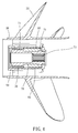
- the marine propeller 10 comprises a propeller hub 22, four propeller blades 30, and a two-piece axle bushing 40.
- the propeller hub 20 comprises an axle hole 22 extended through opposing front and rear ends thereof.
- the propeller blades 30 are equiangularly and radially extended from the outer perimeter of the propeller hub 20.
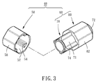
- the two-piece axle bushing 40 is mounted in the axle hole 22 of the propeller hub 20, comprising a first transmission member 50 and a second transmission member 60, as shown in FIG. 3 .
- the first transmission member 50 is made from metal.
- the first transmission member 50 can be made from stainless steel; for use with a low horsepower engine, the first transmission member 50 can be made from aluminum alloy.
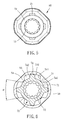
- the first transmission member 50 comprises an accommodation chamber 52 and four longitudinal inner ribs 54. These four longitudinal inner ribs 54 are equiangularly spaced around an inner perimeter of the accommodation chamber 52 and radially projecting toward the inside of the accommodation chamber 52 at a predetermined distance such that a buffer space 56 is defined inside the accommodation chamber 52 between each two adjacent longitudinal inner ribs 54. Further, as shown in FIG. 6 , each longitudinal inner rib 54 comprises two first sloping surfaces 541 respectively located at two opposite sides thereof. Preferably, the first sloping surfaces 541 of each two adjacent longitudinal inner ribs 54 define therebetween a contained angle in the range of 21 ⁇ 25°. Further, the outer perimeter of the first transmission member 50 consists of multiple first planes 58 connected to one another so that the first transmission member 50 can be engaged with the peripheral wall of the axle hole 22 of the propeller hub 20 by the first planes 58.
- the second transmission member 60 comprises a tube shaft 70.
- the tube shaft 70 is made from metal.
- the tube shaft 70 can be made from stainless steel; for use with a low horsepower engine, the tube shaft 70 can be made from aluminum alloy.
- the tube shaft 70 comprises a first transmission segment 71, and a second transmission segment 72 connected to the first transmission segment 71.
- the first transmission segment 71 of the tube shaft 70 is inserted into the accommodation chamber 52 of the first transmission member 50.
- the second transmission member 60 further comprises a shock absorber 80 fixedly surrounding the second transmission segment 72 of the tube shaft 70, and an internal gear 73 formed integral with the inner perimeter of the second transmission segment 72 of the tube shaft 70 (see FIG. 4 and FIG. 5 ).
- the internal gear 73 is meshed with a drive shaft (not shown) of an engine (not shown) so that the tube shaft 70 is rotatable by the drive shaft of the engine.
- the tube shaft 70 further comprises four longitudinal outer ribs 74 and four bearing portions 75. These four longitudinal outer ribs 74 are equiangularly spaced around an inner perimeter of the first transmission segment 71 and radially projecting toward the outside of the first transmission segment 71 at a predetermined distance. Further, each longitudinal outer rib 74 comprises two second sloping surfaces 742 respectively located at two opposite sides thereof. The longitudinal outer ribs 74 of the tube shaft 70 are respectively engaged in the buffer spaces 56 inside the first transmission member 50.
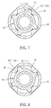
- each longitudinal outer rib 74 of the tube shaft 70 When the longitudinal outer ribs 74 of the tube shaft 70 are respectively engaged with one respective longitudinal inner rib 54 of the first transmission member 50, as shown in FIG. 7 , the second sloping surface 742 of each longitudinal outer rib 74 is abutted against one first sloping surface 541 of one respective longitudinal inner rib 54. At this time, the tube shaft 70 can drive the first transmission member 50 to rotate. As the bearing portions 75 extend radially from the outer perimeter of the second transmission segment 72 a predetermined distance, they assist the tube shaft 70 to bear an output torque from the drive shaft of the engine.
- the shock absorber 80 of the second transmission member 60 is made from, but not limited to, rubber.
- the shock absorber 80 fixedly surrounds the outer perimeter of the second transmission segment 72 of the tube shaft 70 over the bearing portions 75, and, the outer perimeter of the shock absorber 80 consists of multiple second planes 82 that are connected to one another and respectively disposed in line with the first planes 58 of the first transmission member 50 in a flush manner so that the shock absorber 80 can be engaged peripheral wall of the axle hole 22 of the propeller hub 20 by the second planes 82.
- the drive shaft of the engine drives the second transmission member 60 to rotate.
- the longitudinal outer ribs 74 of the second transmission member 60 are disposed in the respective buffer spaces 56 and not engaged with the longitudinal inner ribs 54 of the first transmission member 50, as shown in FIG. 6 , before engagement between the longitudinal outer ribs 74 of the second transmission member 60 and the longitudinal inner ribs 54 of the first transmission member 50, the first transmission member 50 and the propeller hub 20 are immovable.
- the first transmission member 50 begins to rotate with the second transmission member 60.
- the first transmission member 50 and the second transmission member 60 can then transfer the output torque of the engine to the propeller hub 20, causing the propeller blades 30 to rotate with the propeller hub 20 and to further generate a propelling force.
- the shock absorber 80 that fixedly surrounds the outer perimeter of the second transmission segment 72 of the tube shaft 70 over the bearing portions 75 can absorb the shocks thus produced, preventing breaking of the metal tube shaft 70 due to excessively high vibration level and simultaneously giving good protection to the drive shaft. Further, by means of the bearing portions 75, the tube shaft 70 of the second transmission member 60 can bear the output torque of the drive shaft of the engine, and thus, the marine propeller 10 is practical for use with a high horsepower engine.
- the two-piece axle bushing 40 can achieve a soft start-up effect to effectively reduce vibration of the marine propeller 10 in the moment the engine starts up, thereby enhancing start-up stability and smoothness of the marine propeller 10. Further, the two-piece axle bushing 40 not only can absorb shocks to protect the engine but also can bear a high torque for high horsepower application.
Landscapes
- Chemical & Material Sciences (AREA)
- Engineering & Computer Science (AREA)
- Combustion & Propulsion (AREA)
- Mechanical Engineering (AREA)
- Ocean & Marine Engineering (AREA)
- Shafts, Cranks, Connecting Bars, And Related Bearings (AREA)
- Motor Power Transmission Devices (AREA)
Applications Claiming Priority (1)
| Application Number | Priority Date | Filing Date | Title |
|---|---|---|---|
| TW105102518A TWI608962B (zh) | 2016-01-27 | 2016-01-27 | Double-piece shaft sleeve for marine propeller and marine propeller using the same |
Publications (1)
| Publication Number | Publication Date |
|---|---|
| EP3199447A1 true EP3199447A1 (fr) | 2017-08-02 |
Family
ID=56008519
Family Applications (1)
| Application Number | Title | Priority Date | Filing Date |
|---|---|---|---|
| EP16169853.5A Withdrawn EP3199447A1 (fr) | 2016-01-27 | 2016-05-17 | Coussinet d'essieu en deux parties et hélice marine utilisant celui-ci |
Country Status (4)
| Country | Link |
|---|---|
| US (1) | US20170210456A1 (fr) |
| EP (1) | EP3199447A1 (fr) |
| JP (1) | JP2017132458A (fr) |
| TW (1) | TWI608962B (fr) |
Families Citing this family (4)
| Publication number | Priority date | Publication date | Assignee | Title |
|---|---|---|---|---|
| JP6895360B2 (ja) * | 2017-10-13 | 2021-06-30 | Nok株式会社 | 船外機用防振ブッシュ |
| USD894055S1 (en) * | 2018-09-11 | 2020-08-25 | Brunswick Corporation | Shock absorbing hub assembly for supporting a propeller on a marine propulsion apparatus |
| TWI700215B (zh) * | 2019-04-18 | 2020-08-01 | 般若科技股份有限公司 | 船用推進器 |
| US12552512B2 (en) | 2021-08-24 | 2026-02-17 | Mastercraft Boat Company, Llc | Propeller assembly for a boat |
Citations (6)
| Publication number | Priority date | Publication date | Assignee | Title |
|---|---|---|---|---|
| US6383042B1 (en) * | 2000-04-11 | 2002-05-07 | Bombardier Motor Corporation Of America | Axial twist propeller hub |
| US6478543B1 (en) * | 2001-02-12 | 2002-11-12 | Brunswick Corporation | Torque transmitting device for mounting a propeller to a propeller shaft of a marine propulsion system |
| US7086836B1 (en) * | 2004-09-02 | 2006-08-08 | Brunswick Corporation | Dual rate torque transmitting device for a marine propeller |
| TWM310175U (en) | 2006-10-23 | 2007-04-21 | Solas Science & Engineering Co | Boat propeller |
| US20110212657A1 (en) * | 2010-02-26 | 2011-09-01 | Yamaha Hatsudoki Kabushiki Kaisha | Propeller unit for marine vessel propulsion device and marine vessel propulsion device including the same |
| EP2946999A1 (fr) * | 2014-05-20 | 2015-11-25 | Yamaha Hatsudoki Kabushiki Kaisha | Hélice d'un appareil de propulsion de navire et appareil de propulsion de navire comprenant celle-ci |
Family Cites Families (14)
| Publication number | Priority date | Publication date | Assignee | Title |
|---|---|---|---|---|
| US2235605A (en) * | 1937-03-10 | 1941-03-18 | Bugatti Ettore | Screw propeller |
| US2164485A (en) * | 1938-10-21 | 1939-07-04 | Gen Motors Corp | Slip clutch device |
| US4566855A (en) * | 1981-08-28 | 1986-01-28 | Costabile John J | Shock absorbing clutch assembly for marine propeller |
| US4767278A (en) * | 1981-10-06 | 1988-08-30 | Enderlein Jr Emmanuel X | Boat propeller |
| JP2789358B2 (ja) * | 1989-09-26 | 1998-08-20 | 三信工業株式会社 | 船舶推進機用プロペラのダンパラバー組立体 |
| JPH0456697A (ja) * | 1990-06-25 | 1992-02-24 | Suzuki Motor Corp | 船舶用推進機のプロペラ取付構造 |
| WO1996005101A1 (fr) * | 1994-08-16 | 1996-02-22 | Spi (R & D) Pty. Ltd. | Ensemble de montage pour helices |
| US6322407B1 (en) * | 1998-12-11 | 2001-11-27 | Sanshin Kogyo Kabushiki Kaisha | Marine drive transmission |
| US6471481B2 (en) * | 2001-01-02 | 2002-10-29 | Turning Point Propellers, Inc. | Hub assembly for marine propeller |
| JP3133929U (ja) * | 2006-10-23 | 2007-07-26 | 般若科技股▲分▼有限公司 | 船舶用推進器のプロペラ |
| JP2012159196A (ja) * | 2012-03-26 | 2012-08-23 | Yamaha Motor Co Ltd | 船外機 |
| JP2014019341A (ja) * | 2012-07-19 | 2014-02-03 | Yamaha Motor Co Ltd | 船舶推進装置用のダンパユニット、船舶推進装置用のプロペラ、および船舶推進装置 |
| JP5979018B2 (ja) * | 2013-01-22 | 2016-08-24 | ヤマハ発動機株式会社 | プロペラユニット及びプロペラユニット用衝撃吸収部材 |
| CN204647042U (zh) * | 2015-01-28 | 2015-09-16 | 金余和 | 一种减震缓冲轴 |
-
2016
- 2016-01-27 TW TW105102518A patent/TWI608962B/zh not_active IP Right Cessation
- 2016-05-17 EP EP16169853.5A patent/EP3199447A1/fr not_active Withdrawn
- 2016-05-25 US US15/164,224 patent/US20170210456A1/en not_active Abandoned
-
2017
- 2017-01-20 JP JP2017008049A patent/JP2017132458A/ja active Pending
Patent Citations (6)
| Publication number | Priority date | Publication date | Assignee | Title |
|---|---|---|---|---|
| US6383042B1 (en) * | 2000-04-11 | 2002-05-07 | Bombardier Motor Corporation Of America | Axial twist propeller hub |
| US6478543B1 (en) * | 2001-02-12 | 2002-11-12 | Brunswick Corporation | Torque transmitting device for mounting a propeller to a propeller shaft of a marine propulsion system |
| US7086836B1 (en) * | 2004-09-02 | 2006-08-08 | Brunswick Corporation | Dual rate torque transmitting device for a marine propeller |
| TWM310175U (en) | 2006-10-23 | 2007-04-21 | Solas Science & Engineering Co | Boat propeller |
| US20110212657A1 (en) * | 2010-02-26 | 2011-09-01 | Yamaha Hatsudoki Kabushiki Kaisha | Propeller unit for marine vessel propulsion device and marine vessel propulsion device including the same |
| EP2946999A1 (fr) * | 2014-05-20 | 2015-11-25 | Yamaha Hatsudoki Kabushiki Kaisha | Hélice d'un appareil de propulsion de navire et appareil de propulsion de navire comprenant celle-ci |
Also Published As
| Publication number | Publication date |
|---|---|
| TW201726493A (zh) | 2017-08-01 |
| JP2017132458A (ja) | 2017-08-03 |
| US20170210456A1 (en) | 2017-07-27 |
| TWI608962B (zh) | 2017-12-21 |
Similar Documents
| Publication | Publication Date | Title |
|---|---|---|
| EP1961655B1 (fr) | Hélice pour bateau | |
| EP3199447A1 (fr) | Coussinet d'essieu en deux parties et hélice marine utilisant celui-ci | |
| US5908284A (en) | Marine propeller with tube shape shock absorbing means | |
| US6383042B1 (en) | Axial twist propeller hub | |
| KR101606242B1 (ko) | 선박용 추진장치 | |
| CN110316345A (zh) | 一种新型对转桨船舶侧向推进系统 | |
| US6773232B2 (en) | Progressive shear assembly for outboard motors and out drives | |
| KR102376306B1 (ko) | 고토크 충격 드라이브 허브를 갖는 보트용 프로펠러 | |
| CN110863772B (zh) | 一种旋挖钻机动力头 | |
| SE452973B (sv) | Stotabsorberande propeller | |
| AU2008343061A1 (en) | Propeller assembly incorporating spindle with fins and overmolded bushing | |
| US11745842B1 (en) | Damper assemblies and marine propellers with damper assemblies | |
| US2246539A (en) | Variable pitch propeller | |
| CN212267812U (zh) | 螺旋桨及具有其的船舶 | |
| CN201046774Y (zh) | 船用推进器的螺旋桨 | |
| KR101500293B1 (ko) | 허브 볼텍스 캐비테이션 저감을 위한 프로펠러 캡 | |
| RU2554506C2 (ru) | Движительно-рулевая колонка | |
| US12377945B1 (en) | Marine propellers with compression spring sleeve assemblies | |
| KR20160027557A (ko) | 추진 시스템 | |
| CA2212810C (fr) | Helice | |
| CN113879497A (zh) | 螺旋桨及具有其的船舶 | |
| KR101464570B1 (ko) | 허브 볼텍스 캐비테이션 저감을 위한 프로펠러 캡 | |
| BE1011022A3 (fr) | Helice de propulsion. | |
| CN119821650A (zh) | 一种带双重保护的螺旋桨子母传动组件 | |
| KR101542666B1 (ko) | 선박용 추진장치 |
Legal Events
| Date | Code | Title | Description |
|---|---|---|---|
| PUAI | Public reference made under article 153(3) epc to a published international application that has entered the european phase |
Free format text: ORIGINAL CODE: 0009012 |
|
| STAA | Information on the status of an ep patent application or granted ep patent |
Free format text: STATUS: THE APPLICATION HAS BEEN PUBLISHED |
|
| AK | Designated contracting states |
Kind code of ref document: A1 Designated state(s): AL AT BE BG CH CY CZ DE DK EE ES FI FR GB GR HR HU IE IS IT LI LT LU LV MC MK MT NL NO PL PT RO RS SE SI SK SM TR |
|
| AX | Request for extension of the european patent |
Extension state: BA ME |
|
| STAA | Information on the status of an ep patent application or granted ep patent |
Free format text: STATUS: THE APPLICATION IS DEEMED TO BE WITHDRAWN |
|
| 18D | Application deemed to be withdrawn |
Effective date: 20180203 |