EP3199450B1 - Corps d'écoulement pour un aéronef pour l'aspiration d'une couche limite passive - Google Patents
Corps d'écoulement pour un aéronef pour l'aspiration d'une couche limite passive Download PDFInfo
- Publication number
- EP3199450B1 EP3199450B1 EP16153298.1A EP16153298A EP3199450B1 EP 3199450 B1 EP3199450 B1 EP 3199450B1 EP 16153298 A EP16153298 A EP 16153298A EP 3199450 B1 EP3199450 B1 EP 3199450B1
- Authority
- EP
- European Patent Office
- Prior art keywords
- flow
- flow body
- suction
- manifold
- structural component
- Prior art date
- Legal status (The legal status is an assumption and is not a legal conclusion. Google has not performed a legal analysis and makes no representation as to the accuracy of the status listed.)
- Active
Links
Images


Classifications
-
- B—PERFORMING OPERATIONS; TRANSPORTING
- B64—AIRCRAFT; AVIATION; COSMONAUTICS
- B64C—AEROPLANES; HELICOPTERS
- B64C5/00—Stabilising surfaces
- B64C5/06—Fins
-
- B—PERFORMING OPERATIONS; TRANSPORTING
- B64—AIRCRAFT; AVIATION; COSMONAUTICS
- B64C—AEROPLANES; HELICOPTERS
- B64C21/00—Influencing air flow over aircraft surfaces by affecting boundary layer flow
- B64C21/02—Influencing air flow over aircraft surfaces by affecting boundary layer flow by use of slot, ducts, porous areas or the like
-
- B—PERFORMING OPERATIONS; TRANSPORTING
- B64—AIRCRAFT; AVIATION; COSMONAUTICS
- B64C—AEROPLANES; HELICOPTERS
- B64C21/00—Influencing air flow over aircraft surfaces by affecting boundary layer flow
- B64C21/02—Influencing air flow over aircraft surfaces by affecting boundary layer flow by use of slot, ducts, porous areas or the like
- B64C21/06—Influencing air flow over aircraft surfaces by affecting boundary layer flow by use of slot, ducts, porous areas or the like for sucking
-
- B—PERFORMING OPERATIONS; TRANSPORTING
- B64—AIRCRAFT; AVIATION; COSMONAUTICS
- B64C—AEROPLANES; HELICOPTERS
- B64C5/00—Stabilising surfaces
- B64C5/02—Tailplanes
-
- B—PERFORMING OPERATIONS; TRANSPORTING
- B64—AIRCRAFT; AVIATION; COSMONAUTICS
- B64C—AEROPLANES; HELICOPTERS
- B64C2230/00—Boundary layer controls
- B64C2230/04—Boundary layer controls by actively generating fluid flow
-
- Y—GENERAL TAGGING OF NEW TECHNOLOGICAL DEVELOPMENTS; GENERAL TAGGING OF CROSS-SECTIONAL TECHNOLOGIES SPANNING OVER SEVERAL SECTIONS OF THE IPC; TECHNICAL SUBJECTS COVERED BY FORMER USPC CROSS-REFERENCE ART COLLECTIONS [XRACs] AND DIGESTS
- Y02—TECHNOLOGIES OR APPLICATIONS FOR MITIGATION OR ADAPTATION AGAINST CLIMATE CHANGE
- Y02T—CLIMATE CHANGE MITIGATION TECHNOLOGIES RELATED TO TRANSPORTATION
- Y02T50/00—Aeronautics or air transport
- Y02T50/10—Drag reduction
Definitions
- the invention relates to the passive boundary layer suction on a flow body of an aircraft and in particular to a flow body of an aircraft comprising a flow surface exposed to an airstream during flight of the aircraft, at least one perforated area comprising a plurality of openings extending through the flow surface as well as a suction duct for suction of air through the at least one perforated area.
- Influencing the boundary layer on a flow body supports improving the aerodynamic characteristics of the flow body and, more particularly, supports the reduction of its aerodynamic drag.
- the boundary layer control is conducted either through suction, hence enabling extended laminar boundary layers, or through re-energizing the boundary layer by blowing.
- active systems which actively move air into or out of the boundary layer by means of pumps or similar devices
- passive systems are known. Both concepts require a suitable perforation in a dedicated area of an exterior flow surface to allow air to pass through the flow surface.
- US 2013/0270390 A1 shows an aircraft with a partially perforated outer surface as well as a suction profile body, with which a suction force is generated. By applying the suction force to the perforated surface, air is moved through the perforation and thus removed from the boundary layer.
- GB 2 402 196 A discloses a laminar flow nacelle for an aircraft engine, which comprises a porous region at a forward position as well as an aperture further downstream, which leads to a suction of air from the porous region to the aperture for laminarising the flow over an outer surface of the nacelle.
- US 2010/181434 A1 discloses a purging system for a laminar flow control system with a porous skin, a duct and a door assembly, which comprises a second door that is able to produce an opening that faces downstream in order to provide a suction force for drawing air through the porous skin and the duct through the opening.
- FR 3 020 345 A1 discloses a laminar flow nacelle, which comprises an area with a plurality of perforations, which are coupled with a pump through a chamber and a duct, wherein the pump provides a suction force to the perforations and disposes air from a boundary layer of the nacelle to an outflow opening at a lower side of the nacelle.
- US 2009/212165 A1 discloses a method for passive removal of suction air for producing a laminar flow by forming a laminar flow region over an external surface of an aircraft by drawing air through the external surface and into a plenum.
- a pressure differential between the location of the perforation and a second location at or near the flow body may be used.
- a passive suction system needs to fulfil several requirements, which include ensuring the functionality, i.e. providing a sufficient mass flow driven by the pressure differential, minimizing parasitic drag, respecting space constraints interior to the flow surface of the flow body and space allocation requirements, minimizing additional weight and allowing for a maximum suction area and hence laminar flow area.
- the object of the invention is to provide an alternate solution for a flow body of an aircraft, which is adapted for conducting a passive suction of air from the boundary layer of the flow body.
- a flow body of an aircraft comprising a flow surface exposed to an airflow during flight of the aircraft, at least one structural component in form of a front spar attached to an interior of the flow surface, at least one perforated area comprising a plurality of openings extending through the flow surface, a manifold in form of a line section positioned interior to the flow surface in fluid communication with the openings and upstream of the at least one structural component, and a bifurcated arrangement of two suction ducts, each having a first end and a second end, each first end being connected to the manifold, each second end being placed exterior to the flow surface downstream of the at least one structural component, wherein the second ends of both suction ducts are arranged at opposite sides of the flow body.
- the suction ducts each comprise a suction opening facing away from the first end, wherein the suction opening is adapted for inducing a suction force into the respective suction duct when the flow surface is exposed to an airstream during flight, thereby inducing a flow of air from through the openings to the suction opening.
- the flow body of an aircraft is a component that comprises a flow surface, which is exposed to an airflow during flight of the aircraft.
- the flow body is an exterior part that influences the aerodynamic characteristics of the aircraft.
- the flow body may be a wing, a part or a section of a wing, be it in a spanwise or chordwise direction, a part or a section of a tailplane, such as a vertical tailplane, a horizontal tailplane or components thereof.
- the flow body may be an add-on body, which protrudes from a fuselage of the aircraft, a fairing, a wing, or a part of the tailplane, be it the horizontal or the vertical tailplane, into the surrounding of the aircraft.
- still further different flow bodies may be considered and the following description should not be construed as limiting the flow body to any kind mentioned in the following.
- the at least one structural component may preferably be a part of an interior main structure of the flow body, such as a spar or a stringer, for providing dimensional stability.
- an interior main structure of the flow body such as a spar or a stringer
- Common design principles of aircraft and flow bodies thereof are based on the combination of a skin as a shape determining part and a support structure as an interior part.
- the support structure often comprises a set of structural components, which are arranged in a predetermined geometrical relationship and allow to create a lightweight and stiff three-dimensional body.
- the flow body comprises at least one perforated area having openings extending through the flow surface.
- a multitude of separate perforated areas may be considered.
- Each of the at least one perforated area comprises a set of openings, which may be arranged in a regular or irregular pattern or a combination thereof on the flow surface. Also, different patterns may be generated in a single perforated area.
- the openings may comprise a diameter that depends on the airflow conditions, the material of the flow body and the desired porosity and may extend through the flow surface perpendicularly or at an angle thereto that differs from a perpendicular extension.
- the manifold acts as an interface or as a collection device for receiving the air flow that passes the openings into the interior of the flow body and for routing it into the at least one suction duct.
- the at least one suction duct which is coupled with the manifold, induces a suction force on all openings at the same time.
- the manifold may be or lead into a plenum chamber, it may also be realized in the form of a line section or, in other words, a feeder duct.
- the manifold is intended to be a plenum chamber, it may be created by simply providing a wall at a distance to the at least one perforated area in order to enclose a defined space in fluid communication with the at least one suction duct and the exterior of the openings.
- providing a wall may be realized through using a part of a main structure, such as the at least one structural component of the flow body, or by installing a separate wall.
- Locating the manifold upstream of the at least one structural component and placing the suction openings downstream of the at least one structural component requires the suction ducts to extend over the at least one structural component along the flow surface to a region with a suitable pressure and flow condition for inducing a suction force.
- modifications of the at least one structural component are not required, since the at least one suction duct does not need to be routed through the at least one structural component.
- the flow body according to the invention is perfectly suitable for retrofit solutions to already existing aircraft, since a part of a flow body intended for an addition of a boundary layer control may be replaced by the flow body according to the invention without any further modifications.
- the suction opening which faces away from the respective first end of the respective suction duct is placed in a low pressure area to generate a suitable pressure gradient between the porous surface and the suction opening, to primarily ensure the required mass flow and secondly by compensating also the pressure losses in the suction duct.
- the suction opening is flown over by with the airflow around or along the flow body.
- the suction force which is given as the low pressure at the second end multiplied with the cross-sectional area of the suction opening, may be influenced to match the desired airflow through the openings.
- suction ducts are placed exterior to the flow surface, it is preferable to let them extend from the flow surface as little as possible to minimize an unavoidable parasitic drag.
- the positive effect of the boundary layer control clearly overweighs its parasitic drag.
- the individual (effective) diameters of both suction ducts can be reduced, as two separate suction ducts commonly provide the suction force. Also, the parasitic drag induced by the two suction ducts occur symmetrically in relation to a flight direction and do not lead to a (very marginal) asymmetric forces on the aircraft.
- Another advantage of the use of a bifurcated arrangement of two suction ducts lies in the capability to always provide a sufficient suction effect in the manifold even when a distinct side slip of the aircraft occurs, in which case a suction duct on one lateral side of the aircraft produces a much smaller suction force than the other one.
- the flow body further comprises a leading edge, which faces into the airflow during flight, wherein the at least one perforated area is created as a section of the flow surface extending over the leading edge.
- a vertical or horizontal tail plane may be equipped with a partially perforated leading edge region, from which at least one suction duct extends in a downstream direction on the flow surface. Consequently, the front spar as a structural component of the flow body, which is further upstream, does not need to be modified as the at least one suction duct does not need to be routed through it.
- the manifold is located between the leading edge of the flow body and a front spar as the at least one structural component of the flow body due to the above-mentioned reasons.
- a certain pressure field on the exterior surface is produced, which pressure field comprises at least one section having a local pressure lower than upstream of the at least one structural component, wherein the suction opening is located directly upstream of this section of low pressure.
- a section having a minimum pressure is created on the exterior surface.
- the manifold extends substantially parallel to the front spar and the two suction ducts each comprise a bent section between the first end and a section, which is fully placed on the exterior side of the flow surface. This bent section allows to reach from the exterior side of the flow surface into the interior, directly upstream the at least one structural component.
- the cross-sectional surface area of the bent section exceeds the cross-sectional surface area of the suction opening.
- the cross-sectional surface area at the bent section may be at least 50% higher than that at the suction opening. It may also be particularly larger, such as at least twice the cross-sectional surface area at the suction opening.
- the pressure losses which generally depend on the square of the flow velocity and certain other factors, in curved or bent ducts exceeds the pressure loss in a straight duct. The pressure loss may significantly be reduced by reducing the flow velocity, which is accomplished through increasing the cross-sectional surface area.
- Increasing the cross-sectional surface area may be accomplished by widening the suction duct, which means that an extension of the suction duct away from the flow surface is substantially prevented, while a suction duct determining dimension substantially parallel to the flow surface is increased.
- the cross-sectional surface of the bent section extends on a wider dimension on the flow surface than the cross-sectional surface of the suction opening This further leads to reducing the parasitic drag induced by the outer dimensions and shape of the suction duct.
- the suction ducts comprise a cross section, which is at least partially crescent-shaped.
- the suction ducts continuously taper of from a cutout in the flow body, through which the suction ducts extend from an interior to an exterior side, to the suction opening.
- the suction ducts may be bent, i.e. it comprise a bent section.
- the flow body comprises a flow control means, which is adapted for reducing the flow between the manifold and the suction ducts selectively. Reduction or elimination of a flow between the manifold and the suction ducts leads to switching on, reducing or switching off the boundary layer control. This may be helpful in flight phases other than cruise phases, thereby, reducing the danger of contamination, i.e. clogging of the openings.
- the flow control means may be placed at or in the manifold and may comprise an aperture, an orifice, a movable flap or other common devices for influencing an air flow through a duct.
- a space between the perforated area and the at least one structural component may at least partially be closed interior of the flow body so as to form a plenum chamber in which the at least one manifold may be placed, which is connected to the manifold or which constitutes the manifold.
- the flow body according to the invention allows to induce a suction force onto suction ducts in fluid communication with openings of at least one perforated area, without the necessity to modify a primary structure in the flow body. Routing the suction ducts on the exterior flow surface allows to tap a point of lowest pressure, which supports the generation of a suction force.
- a flow body 2 in the form of a vertical tailplane is depicted.
- the flow body 2 comprises a base 4, which adjoins a tail section 6 of a fuselage 8 of an aircraft.
- the flow body 2 comprises a leading edge 10 that faces the airflow, which is indicated with arrows "f".
- a perforated area 12 extends to both sides of the flow body 2 in a downstream direction.
- the perforated area 12 may be considered a curved polygon, e.g. a rectangle or slightly tapered surface covering the leading edge 10 having a multitude of openings 14.
- the openings 14 may be arranged in a regular and/or irregular pattern. Also, the perforated area 12 may be segmented into a multitude of separate perforated areas, depending on the intended volume flow at various locations on the flow body 2.
- the openings 14 allow air to pass through a flow surface 20, which is the outer surface of the flow body 2, to be drawn into an interior of the flow body 2 out of a boundary layer created on the flow surface 20.
- a front spar 16 extends from the base 4 to a tip portion 18 of the flow body 2. Further spars may be arranged inside the flow body 2, which are not depicted for simplification. A skilled person will be readily able to provide a sufficiently stiff support structure having one or more structural components for using the flow body 2 in the desired conditions.
- the front spar 16 is a structural component, which is located at a most forward or upstream position in the flow body 2. Further upstream, the perforated area 12 is placed, which substantially extends over a leading edge area covering the region between the front spar 16 and the leading edge 10. By removal of air through the openings 14, the flow in the boundary layer on this leading edge region is at least partially laminar.
- Fig. 2 exemplarily shows the flow body 2 of Fig. 1 with a schematic isobar plot of a pressure field, which is generated during flight.
- several exemplary isobar lines each show an equal or constant pressure on the flow surface 20.
- In the pressure field there may be a region of lowest pressure 22, which is located downstream the front spar 16.
- a suction duct extending between this region of lowest pressure 22 and a location interior of the perforated area 12 having a higher pressure, a suction force is initiated. This will be explained with following Fig. 3 .
- Fig. 3 again shows the same flow body 2 as in Figs. 1 and 2 and shows a partially sectional view with a suction duct 24, which extends from a manifold 26, which is placed between the front spar 16 and the leading edge 10, and a location 28 just upstream the region of lowest pressure 22.
- the suction duct runs on an exterior side of the flow surface 20 and thereby passes the front spar 16 without having to reach through it. This means that no installation space inside the flow body is required for including the suction duct 24 and its extension to the region of lowest pressure 22. Since only one side of the flow body 2 is depicted the other (hidden) side of the flow body 2 may also comprise such a suction duct 24 extending from the manifold 26 in a symmetrical manner. However, this is not necessary and a skilled person may only provide a single suction duct 24 if desired.
- the suction duct comprises a first end 23 and a second end 25. While the first end 23 is connected to the manifold 26, the second end 25 comprises a suction opening 28, which faces away from the first end 23 and the leading edge 10, respectively.
- Both inlets 30 and 32 are designed as line sections, which are exemplarily extending parallel to the leading edge 10 and which each are open to a side facing away from the manifold 26.
- the space enclosed by the perforated area 12 and limited by the front spar 16 may be closed in order to create a plenum chamber, which receives air that passes through the openings 14, which air is then drawn into the suction duct 24.
- the whole arrangement allows to provide a fluid coupling between the openings 14 in the leading edge region and the suction duct 24.
- Fig. 4 shows an aircraft 33, which more illustratively depicts the arrangement of the flow body 2 in the form of a vertical tailplane at a tail section 6 of the fuselage 8 as well as an exemplary location and dimensional extension of the suction duct 24.
- Fig. 5 shows a more detailed and less schematic design of a part of a flow body 34 in an exemplary embodiment.
- a top view on a cross-section of the flow body 34 is shown, which comprises a manifold 36 between a front spar 38 and a leading edge 40, to which manifold 36 a bifurcated arrangement of two suction ducts 42 and 44 is connected.
- Both suction ducts 42 and 44 comprise a first end 41 and 45, respectively, and a second end 43 and 47, respectively.
- a flow surface 46 of the flow body 34 requires two cutouts 48 and 50, through which the suction ducts 42 and 44 extend. From the cutouts 48 and 50, which are placed just upstream the front spar 38, the suction ducts 42 and 44 extend further downstream and run alongside the exterior of the flow surface 46.
- the suction ducts 42 and 44 have a suction opening 56 and 58, respectively, which faces away from the leading edge 40 and the manifold 36.
- the cross-sectional surfaces of the openings 56 and 58 each enclose an angle ⁇ and ⁇ , which are less than 90° to the streamline of the surrounding airstream.
- the angles of the cross-sectional surfaces of the openings 56 and 58 may also be distinctly higher, depending on the optimisation of the overal design of the flow body 34.
- the low static pressure due to the air flow around the flow body is the main driver for the pressure difference between the regions of lowest pressure 52 and 54 and the manifold 36 supports the suction.
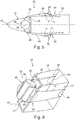
- Fig. 6 shows a three-dimensional drawing of a part of the flow body 34 of Fig. 5 to illustrate a possible shape of the local cross-sectional surfaces of the suction ducts 42 and 44.
- the extension away from the flow surface 46 is minimised through providing a crescent shape.
- both suction ducts 42 and 44 require a bent section 60 and 62. In these, the air flow changes its direction about approximately 90 degrees, which would lead to an additional pressure loss, depending on the flow velocity.
- the manifold 36 may be realized as depicted, i.e. through simply providing a rather short duct section, which is open to both sides, wherein a longitudinal axis 64 of the manifold 36 runs parallel to the front spar 38. Both suction ducts 42 and 44 are connected to the manifold 36 substantially perpendicular to the longitudinal axis 64. Furthermore, the local cross-sectional surface areas of both suction ducts 42 and 44 may decrease along the course from the bent area 60 or 62 to the suction opening 56 or 58 continuously, e.g. by narrowing the extension on the flow surface 46. As stated before, a trade-off between the parasitic drag and the positive effects of the boundary layer control has to be done based on the boundary conditions of the respective aircraft for providing a detailed design of the suction ducts 42 and 44.
Landscapes
- Engineering & Computer Science (AREA)
- Aviation & Aerospace Engineering (AREA)
- Chemical & Material Sciences (AREA)
- Combustion & Propulsion (AREA)
- Structures Of Non-Positive Displacement Pumps (AREA)
- Jet Pumps And Other Pumps (AREA)
- Aerodynamic Tests, Hydrodynamic Tests, Wind Tunnels, And Water Tanks (AREA)
Claims (14)
- Corps d'écoulement (2, 34) d'un aéronef, comprenant :une surface d'écoulement (20, 46) exposée à un courant d'air pendant le vol de l'aéronef,au moins un composant structurel (16, 38) sous la forme d'un longeron avant (16, 38) fixé à un intérieur de la surface d'écoulement (20, 46),au moins une zone perforée (12) comprenant une pluralité d'ouvertures (14) s'étendant à travers la surface d'écoulement (20, 46),un collecteur (26, 36) sous la forme d'une section de ligne, positionné à l'intérieur de la surface d'écoulement (20, 46) en communication fluidique avec les ouvertures (14) et en amont de l'au moins un composant structurel (16, 38), etun agencement bifurqué de deux conduits d'aspiration (24, 42), ayant chacun une première extrémité (23, 41, 45) et une seconde extrémité (25, 43, 47), chaque première extrémité (23, 41, 45) étant reliée au collecteur (26, 36), chaque seconde extrémité (25, 43, 47) étant disposée à l'extérieur de la surface d'écoulement (20, 46) en aval de l'au moins un composant structurel (16, 38), les secondes extrémités (25, 43, 47) des deux conduits d'aspiration étant situées à des côtés opposés du corps d'écoulement (2, 34),les conduits d'aspiration (24, 42, 44) comprenant chacun une ouverture d'aspiration (28, 56, 58) faisant face à l'opposé de la première extrémité (23, 41, 45),l'ouverture d'aspiration (28, 56, 58) étant conçue pour induire une force d'aspiration dans le conduit d'aspiration (24, 42) respectif lorsque la surface d'écoulement (20, 46) est exposée à un courant d'air en vol, induisant ainsi un écoulement d'air d'au travers les ouvertures (14) à l'ouverture d'aspiration (28, 56, 58).
- Corps d'écoulement (2, 34) selon la revendication 1, comprenant en outre un bord d'attaque (10, 40), qui fait face au courant d'air en vol,
l'au moins une zone perforée (12) étant créée sous la forme d'une section de la surface d'écoulement (20, 46) s'étendant au-dessus du bord d'attaque (10, 40). - Corps d'écoulement (2, 34) selon la revendication 2,
le collecteur (26, 36) étant situé entre le bord d'attaque (10, 40) du corps d'écoulement (2, 34) et un longeron avant comme l'au moins un composant structurel (16, 38) du corps d'écoulement (2, 34). - Corps d'écoulement (2, 34) selon l'une quelconque des revendications précédentes,
un certain champ de pression sur la surface d'écoulement (20, 46) étant produit, ledit champ de pression comprenant au moins une région (22) ayant une pression locale inférieure à celle en amont de l'au moins un composant structurel (16, 38),
l'ouverture d'aspiration (28, 56, 58) étant située directement en amont de l'au moins une région (22) de pression inférieure. - Corps d'écoulement (2, 34) selon la revendication 1,
le collecteur (26, 36) s'étendant sensiblement parallèlement à l'au moins un composant structurel (16, 38) et
les conduits d'aspiration (42, 44) comprenant chacun une section courbée (60, 62) entre la première extrémité (23, 41, 45) et une section, qui est entièrement placée sur le côté extérieur de la surface d'écoulement (20, 46) . - Corps d'écoulement (2, 34) selon la revendication 5,
la surface de la section transversale de la section courbée (60, 62) dépassant de la surface de la section transversale de l'ouverture d'aspiration (28, 56, 58). - Corps d'écoulement (2, 34) selon l'une quelconque des revendications précédentes,
les conduits d'aspiration (24, 42, 44) comprenant une section transversale, qui est au moins partiellement en forme de croissant. - Corps d'écoulement (2, 34) selon l'une quelconque des revendications précédentes,
les conduits d'aspiration (24, 42, 44) se rétrécissant en continu à partir d'une découpe (48) dans le corps d'écoulement (2, 34), à travers laquelle les conduits d'aspiration (24, 42, 44) s'étendent d'un côté intérieur vers un côté extérieur, jusqu'à l'ouverture d'aspiration (28, 56, 58). - Corps d'écoulement (2, 34) selon l'une quelconque des revendications précédentes,
le collecteur (26, 36) comprenant au moins une entrée (30, 32) s'étendant dans un espace formé entre le bord d'attaque (10, 40) et l'au moins un composant structurel (16, 38). - Corps d'écoulement (2, 34) selon l'une quelconque des revendications précédentes,
comprenant en outre un moyen de régulation d'écoulement, qui est conçu pour réduire sélectivement l'écoulement d'air entre le collecteur (26, 36) et les conduits d'aspiration (24, 42, 44). - Corps d'écoulement (2, 34) selon l'une quelconque des revendications précédentes,
le corps d'écoulement (2, 34) étant conçu sous la forme d'un stabilisateur vertical ou d'un stabilisateur horizontal, la zone perforée (12) étant disposée dans la région d'un bord d'attaque (10, 40) du corps d'écoulement (2, 34). - Corps d'écoulement (2, 34) selon l'une quelconque des revendications précédentes,
un espace entre la zone perforée (12) et l'au moins un composant structurel (16, 38) étant au moins partiellement fermé à l'intérieur du corps d'écoulement (2, 34) de sorte à former une chambre de répartition d'air. - Aéronef ayant un fuselage et un corps d'écoulement (2, 34) selon l'une quelconque des revendications 1 à 12.
- Aéronef selon la revendication 13, le corps d'écoulement (2, 34) étant un stabilisateur vertical.
Priority Applications (4)
| Application Number | Priority Date | Filing Date | Title |
|---|---|---|---|
| ES16153298T ES2736527T3 (es) | 2016-01-29 | 2016-01-29 | Cuerpo de flujo para una aeronave para la aspiración de una capa límite pasiva |
| EP16153298.1A EP3199450B1 (fr) | 2016-01-29 | 2016-01-29 | Corps d'écoulement pour un aéronef pour l'aspiration d'une couche limite passive |
| US15/413,836 US10472052B2 (en) | 2016-01-29 | 2017-01-24 | Flow body for an aircraft for passive boundary layer suction |
| CN201710060982.7A CN107021207B (zh) | 2016-01-29 | 2017-01-25 | 用于被动式边界层吸入的飞行器用流装置 |
Applications Claiming Priority (1)
| Application Number | Priority Date | Filing Date | Title |
|---|---|---|---|
| EP16153298.1A EP3199450B1 (fr) | 2016-01-29 | 2016-01-29 | Corps d'écoulement pour un aéronef pour l'aspiration d'une couche limite passive |
Publications (2)
| Publication Number | Publication Date |
|---|---|
| EP3199450A1 EP3199450A1 (fr) | 2017-08-02 |
| EP3199450B1 true EP3199450B1 (fr) | 2019-05-15 |
Family
ID=55272306
Family Applications (1)
| Application Number | Title | Priority Date | Filing Date |
|---|---|---|---|
| EP16153298.1A Active EP3199450B1 (fr) | 2016-01-29 | 2016-01-29 | Corps d'écoulement pour un aéronef pour l'aspiration d'une couche limite passive |
Country Status (4)
| Country | Link |
|---|---|
| US (1) | US10472052B2 (fr) |
| EP (1) | EP3199450B1 (fr) |
| CN (1) | CN107021207B (fr) |
| ES (1) | ES2736527T3 (fr) |
Families Citing this family (9)
| Publication number | Priority date | Publication date | Assignee | Title |
|---|---|---|---|---|
| KR101951666B1 (ko) * | 2017-10-05 | 2019-02-25 | 윤태기 | 촬영용 드론 및 그 제어 방법 |
| EP3466811B1 (fr) * | 2017-10-09 | 2023-06-21 | Airbus Operations GmbH | Empennage vertical pour la régulation de l'écoulement |
| EP3746362B1 (fr) * | 2018-01-31 | 2024-03-06 | Airbus Operations GmbH | Profil aérodynamique pour régulation de débit |
| EP3539863B1 (fr) * | 2018-03-15 | 2021-06-30 | Airbus Operations GmbH | Structure de bord d'attaque pour système de commande d'écoulement d'un aéronef |
| EP3604125A1 (fr) | 2018-07-30 | 2020-02-05 | Airbus Operations GmbH | Corps d'écoulement d'un aéronef et aéronef |
| JP7206129B2 (ja) | 2019-02-26 | 2023-01-17 | 三菱重工業株式会社 | 翼及びこれを備えた機械 |
| ES2944554T3 (es) * | 2019-04-03 | 2023-06-22 | Airbus Operations Slu | Conducto mezclador de flujo para un sistema de sangrado |
| US12466548B2 (en) * | 2023-11-17 | 2025-11-11 | Rtx Corporation | Aircraft vertical stabilizer with air system |
| US12420914B2 (en) * | 2023-12-29 | 2025-09-23 | Rtx Corporation | Aircraft airframe component with air system |
Family Cites Families (13)
| Publication number | Priority date | Publication date | Assignee | Title |
|---|---|---|---|---|
| US2266529A (en) * | 1938-10-26 | 1941-12-16 | George H Wright | Aircraft control device |
| US2428585A (en) * | 1943-12-27 | 1947-10-07 | Curtiss Wright Corp | Venturi fitting |
| DE19643069C2 (de) * | 1996-10-18 | 1999-03-25 | Daimler Benz Aerospace Airbus | Seitenleitwerksstrukur für ein Flugzeug |
| US20030150962A1 (en) * | 2002-02-12 | 2003-08-14 | Bela Orban | Method for controlling and delaying the separation of flow from a solid surface by suction coupling (controlling separation by suction coupling, CSSC) |
| US6866233B2 (en) * | 2003-01-03 | 2005-03-15 | Orbital Research Inc. | Reconfigurable porous technology for fluid flow control and method of controlling flow |
| GB2402196B (en) * | 2003-05-29 | 2006-05-17 | Rolls Royce Plc | A laminar flow nacelle for an aircraft engine |
| US7866609B2 (en) * | 2007-06-15 | 2011-01-11 | The Boeing Company | Passive removal of suction air for laminar flow control, and associated systems and methods |
| US8128037B2 (en) * | 2009-01-19 | 2012-03-06 | The Boeing Company | Apparatus and method for passive purging of micro-perforated aerodynamic surfaces |
| US8245976B2 (en) * | 2009-01-19 | 2012-08-21 | The Boeing Company | Door assembly for laminar flow control system |
| DE102012006194B4 (de) | 2012-03-27 | 2021-02-04 | Airbus Operations Gmbh | Flugzeug mit einem Flugzeugrumpf und einer Luft absaugenden Flugzeugrumpfkomponente |
| US9701399B1 (en) * | 2013-03-18 | 2017-07-11 | Techdyne Llc | Parasitic drag induced boundary layer reduction system and method |
| FR3007423B1 (fr) | 2013-06-21 | 2015-06-05 | Constellium France | Element de structure extrados en alliage aluminium cuivre lithium |
| US9789954B2 (en) * | 2014-04-25 | 2017-10-17 | Rohr, Inc. | Method of controlling boundary layer flow |
-
2016
- 2016-01-29 EP EP16153298.1A patent/EP3199450B1/fr active Active
- 2016-01-29 ES ES16153298T patent/ES2736527T3/es active Active
-
2017
- 2017-01-24 US US15/413,836 patent/US10472052B2/en active Active
- 2017-01-25 CN CN201710060982.7A patent/CN107021207B/zh active Active
Non-Patent Citations (1)
| Title |
|---|
| None * |
Also Published As
| Publication number | Publication date |
|---|---|
| US20170217568A1 (en) | 2017-08-03 |
| CN107021207B (zh) | 2021-08-17 |
| CN107021207A (zh) | 2017-08-08 |
| EP3199450A1 (fr) | 2017-08-02 |
| US10472052B2 (en) | 2019-11-12 |
| ES2736527T3 (es) | 2020-01-02 |
Similar Documents
| Publication | Publication Date | Title |
|---|---|---|
| EP3199450B1 (fr) | Corps d'écoulement pour un aéronef pour l'aspiration d'une couche limite passive | |
| EP2644496B1 (fr) | Surface aérodynamique pour aéronef, aéronef et procédé pour améliorer la portance d'une telle surface | |
| EP2167380B1 (fr) | Fuseau-moteur d'un avion comportant un dispositif de génération de tourbillons | |
| EP3031713B1 (fr) | Nervure d'aile d'aéronef | |
| EP2644497B1 (fr) | Aile pour un aéronef, aéronef et procédé pour réduire la traînée aérodynamique et améliorer la portance maximale | |
| US7866609B2 (en) | Passive removal of suction air for laminar flow control, and associated systems and methods | |
| EP3284667B1 (fr) | Agencement d'extrémité d'aile ayant des vortilons fixés à une surface inférieure, aéronef comportant un tel agencement d'extrémité et utilisation des vortilons sur une extrémité | |
| CN103625635B (zh) | 具有表面、前缘和主动气流控制系统的气流装置及其交通工具 | |
| CN104703878B (zh) | 具有形成层流边界层流动的系统的飞机机翼 | |
| CN102596717B (zh) | 用于飞机的流动体 | |
| EP3539863B1 (fr) | Structure de bord d'attaque pour système de commande d'écoulement d'un aéronef | |
| US9701399B1 (en) | Parasitic drag induced boundary layer reduction system and method | |
| CN101896401A (zh) | 用于减小飞机的尾涡的翼尖延长部 | |
| US20190092456A1 (en) | Ducts for laminar flow control systems | |
| CN107054612A (zh) | 形成空气动力学翼型件的后缘并且包括鼓风系统的装置 | |
| EP2995552B1 (fr) | Chambre dans un profil aérodynamique | |
| EP3310653B1 (fr) | Commande d'écoulement de fluide pour un profil aérodynamique | |
| US11208202B2 (en) | Flow body of an aircraft and aircraft | |
| JPS595777B2 (ja) | 航空機搭載ガスタ−ビンエンジンの空気吸入装置 | |
| US12534212B1 (en) | Passive, low-drag device for pylon-nacelle juncture flow separation mitigation |
Legal Events
| Date | Code | Title | Description |
|---|---|---|---|
| PUAI | Public reference made under article 153(3) epc to a published international application that has entered the european phase |
Free format text: ORIGINAL CODE: 0009012 |
|
| STAA | Information on the status of an ep patent application or granted ep patent |
Free format text: STATUS: THE APPLICATION HAS BEEN PUBLISHED |
|
| AK | Designated contracting states |
Kind code of ref document: A1 Designated state(s): AL AT BE BG CH CY CZ DE DK EE ES FI FR GB GR HR HU IE IS IT LI LT LU LV MC MK MT NL NO PL PT RO RS SE SI SK SM TR |
|
| AX | Request for extension of the european patent |
Extension state: BA ME |
|
| STAA | Information on the status of an ep patent application or granted ep patent |
Free format text: STATUS: REQUEST FOR EXAMINATION WAS MADE |
|
| 17P | Request for examination filed |
Effective date: 20180202 |
|
| RBV | Designated contracting states (corrected) |
Designated state(s): AL AT BE BG CH CY CZ DE DK EE ES FI FR GB GR HR HU IE IS IT LI LT LU LV MC MK MT NL NO PL PT RO RS SE SI SK SM TR |
|
| GRAP | Despatch of communication of intention to grant a patent |
Free format text: ORIGINAL CODE: EPIDOSNIGR1 |
|
| STAA | Information on the status of an ep patent application or granted ep patent |
Free format text: STATUS: GRANT OF PATENT IS INTENDED |
|
| RIC1 | Information provided on ipc code assigned before grant |
Ipc: B64C 21/06 20060101ALI20181030BHEP Ipc: B64C 5/06 20060101AFI20181030BHEP |
|
| INTG | Intention to grant announced |
Effective date: 20181205 |
|
| GRAS | Grant fee paid |
Free format text: ORIGINAL CODE: EPIDOSNIGR3 |
|
| GRAA | (expected) grant |
Free format text: ORIGINAL CODE: 0009210 |
|
| STAA | Information on the status of an ep patent application or granted ep patent |
Free format text: STATUS: THE PATENT HAS BEEN GRANTED |
|
| AK | Designated contracting states |
Kind code of ref document: B1 Designated state(s): AL AT BE BG CH CY CZ DE DK EE ES FI FR GB GR HR HU IE IS IT LI LT LU LV MC MK MT NL NO PL PT RO RS SE SI SK SM TR |
|
| REG | Reference to a national code |
Ref country code: CH Ref legal event code: EP |
|
| REG | Reference to a national code |
Ref country code: DE Ref legal event code: R096 Ref document number: 602016013848 Country of ref document: DE |
|
| REG | Reference to a national code |
Ref country code: IE Ref legal event code: FG4D |
|
| REG | Reference to a national code |
Ref country code: NL Ref legal event code: MP Effective date: 20190515 |
|
| REG | Reference to a national code |
Ref country code: LT Ref legal event code: MG4D |
|
| PG25 | Lapsed in a contracting state [announced via postgrant information from national office to epo] |
Ref country code: NL Free format text: LAPSE BECAUSE OF FAILURE TO SUBMIT A TRANSLATION OF THE DESCRIPTION OR TO PAY THE FEE WITHIN THE PRESCRIBED TIME-LIMIT Effective date: 20190515 Ref country code: LT Free format text: LAPSE BECAUSE OF FAILURE TO SUBMIT A TRANSLATION OF THE DESCRIPTION OR TO PAY THE FEE WITHIN THE PRESCRIBED TIME-LIMIT Effective date: 20190515 Ref country code: HR Free format text: LAPSE BECAUSE OF FAILURE TO SUBMIT A TRANSLATION OF THE DESCRIPTION OR TO PAY THE FEE WITHIN THE PRESCRIBED TIME-LIMIT Effective date: 20190515 Ref country code: FI Free format text: LAPSE BECAUSE OF FAILURE TO SUBMIT A TRANSLATION OF THE DESCRIPTION OR TO PAY THE FEE WITHIN THE PRESCRIBED TIME-LIMIT Effective date: 20190515 Ref country code: PT Free format text: LAPSE BECAUSE OF FAILURE TO SUBMIT A TRANSLATION OF THE DESCRIPTION OR TO PAY THE FEE WITHIN THE PRESCRIBED TIME-LIMIT Effective date: 20190915 Ref country code: AL Free format text: LAPSE BECAUSE OF FAILURE TO SUBMIT A TRANSLATION OF THE DESCRIPTION OR TO PAY THE FEE WITHIN THE PRESCRIBED TIME-LIMIT Effective date: 20190515 Ref country code: SE Free format text: LAPSE BECAUSE OF FAILURE TO SUBMIT A TRANSLATION OF THE DESCRIPTION OR TO PAY THE FEE WITHIN THE PRESCRIBED TIME-LIMIT Effective date: 20190515 Ref country code: NO Free format text: LAPSE BECAUSE OF FAILURE TO SUBMIT A TRANSLATION OF THE DESCRIPTION OR TO PAY THE FEE WITHIN THE PRESCRIBED TIME-LIMIT Effective date: 20190815 |
|
| PG25 | Lapsed in a contracting state [announced via postgrant information from national office to epo] |
Ref country code: LV Free format text: LAPSE BECAUSE OF FAILURE TO SUBMIT A TRANSLATION OF THE DESCRIPTION OR TO PAY THE FEE WITHIN THE PRESCRIBED TIME-LIMIT Effective date: 20190515 Ref country code: GR Free format text: LAPSE BECAUSE OF FAILURE TO SUBMIT A TRANSLATION OF THE DESCRIPTION OR TO PAY THE FEE WITHIN THE PRESCRIBED TIME-LIMIT Effective date: 20190816 Ref country code: RS Free format text: LAPSE BECAUSE OF FAILURE TO SUBMIT A TRANSLATION OF THE DESCRIPTION OR TO PAY THE FEE WITHIN THE PRESCRIBED TIME-LIMIT Effective date: 20190515 Ref country code: BG Free format text: LAPSE BECAUSE OF FAILURE TO SUBMIT A TRANSLATION OF THE DESCRIPTION OR TO PAY THE FEE WITHIN THE PRESCRIBED TIME-LIMIT Effective date: 20190815 |
|
| REG | Reference to a national code |
Ref country code: AT Ref legal event code: MK05 Ref document number: 1133124 Country of ref document: AT Kind code of ref document: T Effective date: 20190515 |
|
| REG | Reference to a national code |
Ref country code: ES Ref legal event code: FG2A Ref document number: 2736527 Country of ref document: ES Kind code of ref document: T3 Effective date: 20200102 |
|
| PG25 | Lapsed in a contracting state [announced via postgrant information from national office to epo] |
Ref country code: CZ Free format text: LAPSE BECAUSE OF FAILURE TO SUBMIT A TRANSLATION OF THE DESCRIPTION OR TO PAY THE FEE WITHIN THE PRESCRIBED TIME-LIMIT Effective date: 20190515 Ref country code: EE Free format text: LAPSE BECAUSE OF FAILURE TO SUBMIT A TRANSLATION OF THE DESCRIPTION OR TO PAY THE FEE WITHIN THE PRESCRIBED TIME-LIMIT Effective date: 20190515 Ref country code: AT Free format text: LAPSE BECAUSE OF FAILURE TO SUBMIT A TRANSLATION OF THE DESCRIPTION OR TO PAY THE FEE WITHIN THE PRESCRIBED TIME-LIMIT Effective date: 20190515 Ref country code: DK Free format text: LAPSE BECAUSE OF FAILURE TO SUBMIT A TRANSLATION OF THE DESCRIPTION OR TO PAY THE FEE WITHIN THE PRESCRIBED TIME-LIMIT Effective date: 20190515 Ref country code: SK Free format text: LAPSE BECAUSE OF FAILURE TO SUBMIT A TRANSLATION OF THE DESCRIPTION OR TO PAY THE FEE WITHIN THE PRESCRIBED TIME-LIMIT Effective date: 20190515 |
|
| REG | Reference to a national code |
Ref country code: DE Ref legal event code: R097 Ref document number: 602016013848 Country of ref document: DE |
|
| PG25 | Lapsed in a contracting state [announced via postgrant information from national office to epo] |
Ref country code: IT Free format text: LAPSE BECAUSE OF FAILURE TO SUBMIT A TRANSLATION OF THE DESCRIPTION OR TO PAY THE FEE WITHIN THE PRESCRIBED TIME-LIMIT Effective date: 20190515 Ref country code: SM Free format text: LAPSE BECAUSE OF FAILURE TO SUBMIT A TRANSLATION OF THE DESCRIPTION OR TO PAY THE FEE WITHIN THE PRESCRIBED TIME-LIMIT Effective date: 20190515 |
|
| PLBE | No opposition filed within time limit |
Free format text: ORIGINAL CODE: 0009261 |
|
| STAA | Information on the status of an ep patent application or granted ep patent |
Free format text: STATUS: NO OPPOSITION FILED WITHIN TIME LIMIT |
|
| PG25 | Lapsed in a contracting state [announced via postgrant information from national office to epo] |
Ref country code: TR Free format text: LAPSE BECAUSE OF FAILURE TO SUBMIT A TRANSLATION OF THE DESCRIPTION OR TO PAY THE FEE WITHIN THE PRESCRIBED TIME-LIMIT Effective date: 20190515 |
|
| 26N | No opposition filed |
Effective date: 20200218 |
|
| PG25 | Lapsed in a contracting state [announced via postgrant information from national office to epo] |
Ref country code: PL Free format text: LAPSE BECAUSE OF FAILURE TO SUBMIT A TRANSLATION OF THE DESCRIPTION OR TO PAY THE FEE WITHIN THE PRESCRIBED TIME-LIMIT Effective date: 20190515 |
|
| PG25 | Lapsed in a contracting state [announced via postgrant information from national office to epo] |
Ref country code: SI Free format text: LAPSE BECAUSE OF FAILURE TO SUBMIT A TRANSLATION OF THE DESCRIPTION OR TO PAY THE FEE WITHIN THE PRESCRIBED TIME-LIMIT Effective date: 20190515 |
|
| PG25 | Lapsed in a contracting state [announced via postgrant information from national office to epo] |
Ref country code: MC Free format text: LAPSE BECAUSE OF FAILURE TO SUBMIT A TRANSLATION OF THE DESCRIPTION OR TO PAY THE FEE WITHIN THE PRESCRIBED TIME-LIMIT Effective date: 20190515 |
|
| REG | Reference to a national code |
Ref country code: CH Ref legal event code: PL |
|
| REG | Reference to a national code |
Ref country code: BE Ref legal event code: MM Effective date: 20200131 |
|
| PG25 | Lapsed in a contracting state [announced via postgrant information from national office to epo] |
Ref country code: LU Free format text: LAPSE BECAUSE OF NON-PAYMENT OF DUE FEES Effective date: 20200129 Ref country code: FR Free format text: LAPSE BECAUSE OF NON-PAYMENT OF DUE FEES Effective date: 20200131 |
|
| PG25 | Lapsed in a contracting state [announced via postgrant information from national office to epo] |
Ref country code: CH Free format text: LAPSE BECAUSE OF NON-PAYMENT OF DUE FEES Effective date: 20200131 Ref country code: LI Free format text: LAPSE BECAUSE OF NON-PAYMENT OF DUE FEES Effective date: 20200131 Ref country code: BE Free format text: LAPSE BECAUSE OF NON-PAYMENT OF DUE FEES Effective date: 20200131 |
|
| PG25 | Lapsed in a contracting state [announced via postgrant information from national office to epo] |
Ref country code: IE Free format text: LAPSE BECAUSE OF NON-PAYMENT OF DUE FEES Effective date: 20200129 |
|
| PGFP | Annual fee paid to national office [announced via postgrant information from national office to epo] |
Ref country code: DE Payment date: 20210120 Year of fee payment: 6 Ref country code: GB Payment date: 20210121 Year of fee payment: 6 Ref country code: ES Payment date: 20210326 Year of fee payment: 6 |
|
| PG25 | Lapsed in a contracting state [announced via postgrant information from national office to epo] |
Ref country code: MT Free format text: LAPSE BECAUSE OF FAILURE TO SUBMIT A TRANSLATION OF THE DESCRIPTION OR TO PAY THE FEE WITHIN THE PRESCRIBED TIME-LIMIT Effective date: 20190515 Ref country code: CY Free format text: LAPSE BECAUSE OF FAILURE TO SUBMIT A TRANSLATION OF THE DESCRIPTION OR TO PAY THE FEE WITHIN THE PRESCRIBED TIME-LIMIT Effective date: 20190515 |
|
| PG25 | Lapsed in a contracting state [announced via postgrant information from national office to epo] |
Ref country code: RO Free format text: LAPSE BECAUSE OF FAILURE TO SUBMIT A TRANSLATION OF THE DESCRIPTION OR TO PAY THE FEE WITHIN THE PRESCRIBED TIME-LIMIT Effective date: 20190515 Ref country code: MK Free format text: LAPSE BECAUSE OF FAILURE TO SUBMIT A TRANSLATION OF THE DESCRIPTION OR TO PAY THE FEE WITHIN THE PRESCRIBED TIME-LIMIT Effective date: 20190515 Ref country code: IS Free format text: LAPSE BECAUSE OF FAILURE TO SUBMIT A TRANSLATION OF THE DESCRIPTION OR TO PAY THE FEE WITHIN THE PRESCRIBED TIME-LIMIT Effective date: 20190915 |
|
| REG | Reference to a national code |
Ref country code: DE Ref legal event code: R119 Ref document number: 602016013848 Country of ref document: DE |
|
| GBPC | Gb: european patent ceased through non-payment of renewal fee |
Effective date: 20220129 |
|
| PG25 | Lapsed in a contracting state [announced via postgrant information from national office to epo] |
Ref country code: GB Free format text: LAPSE BECAUSE OF NON-PAYMENT OF DUE FEES Effective date: 20220129 Ref country code: DE Free format text: LAPSE BECAUSE OF NON-PAYMENT OF DUE FEES Effective date: 20220802 |
|
| REG | Reference to a national code |
Ref country code: ES Ref legal event code: FD2A Effective date: 20230303 |
|
| PG25 | Lapsed in a contracting state [announced via postgrant information from national office to epo] |
Ref country code: ES Free format text: LAPSE BECAUSE OF NON-PAYMENT OF DUE FEES Effective date: 20220130 |