EP3199585A1 - Rohr und luftwartungsreifen mit solch einem rohr - Google Patents
Rohr und luftwartungsreifen mit solch einem rohr Download PDFInfo
- Publication number
- EP3199585A1 EP3199585A1 EP17153449.8A EP17153449A EP3199585A1 EP 3199585 A1 EP3199585 A1 EP 3199585A1 EP 17153449 A EP17153449 A EP 17153449A EP 3199585 A1 EP3199585 A1 EP 3199585A1
- Authority
- EP
- European Patent Office
- Prior art keywords
- tube
- groove
- tire
- self
- rubber
- Prior art date
- Legal status (The legal status is an assumption and is not a legal conclusion. Google has not performed a legal analysis and makes no representation as to the accuracy of the status listed.)
- Granted
Links
Images


Classifications
-
- B—PERFORMING OPERATIONS; TRANSPORTING
- B60—VEHICLES IN GENERAL
- B60C—VEHICLE TYRES; TYRE INFLATION; TYRE CHANGING; CONNECTING VALVES TO INFLATABLE ELASTIC BODIES IN GENERAL; DEVICES OR ARRANGEMENTS RELATED TO TYRES
- B60C1/00—Tyres characterised by the chemical composition or the physical arrangement or mixture of the composition
-
- B—PERFORMING OPERATIONS; TRANSPORTING
- B60—VEHICLES IN GENERAL
- B60C—VEHICLE TYRES; TYRE INFLATION; TYRE CHANGING; CONNECTING VALVES TO INFLATABLE ELASTIC BODIES IN GENERAL; DEVICES OR ARRANGEMENTS RELATED TO TYRES
- B60C23/00—Devices for measuring, signalling, controlling, or distributing tyre pressure or temperature, specially adapted for mounting on vehicles; Arrangement of tyre inflating devices on vehicles, e.g. of pumps or of tanks; Tyre cooling arrangements
- B60C23/10—Arrangement of tyre-inflating pumps mounted on vehicles
- B60C23/12—Arrangement of tyre-inflating pumps mounted on vehicles operated by a running wheel
- B60C23/121—Arrangement of tyre-inflating pumps mounted on vehicles operated by a running wheel the pumps being mounted on the tyres
- B60C23/123—Elongate peristaltic pumps
-
- B—PERFORMING OPERATIONS; TRANSPORTING
- B60—VEHICLES IN GENERAL
- B60C—VEHICLE TYRES; TYRE INFLATION; TYRE CHANGING; CONNECTING VALVES TO INFLATABLE ELASTIC BODIES IN GENERAL; DEVICES OR ARRANGEMENTS RELATED TO TYRES
- B60C23/00—Devices for measuring, signalling, controlling, or distributing tyre pressure or temperature, specially adapted for mounting on vehicles; Arrangement of tyre inflating devices on vehicles, e.g. of pumps or of tanks; Tyre cooling arrangements
- B60C23/10—Arrangement of tyre-inflating pumps mounted on vehicles
- B60C23/12—Arrangement of tyre-inflating pumps mounted on vehicles operated by a running wheel
- B60C23/135—Arrangement of tyre-inflating pumps mounted on vehicles operated by a running wheel activated due to tyre deformation
-
- C—CHEMISTRY; METALLURGY
- C08—ORGANIC MACROMOLECULAR COMPOUNDS; THEIR PREPARATION OR CHEMICAL WORKING-UP; COMPOSITIONS BASED THEREON
- C08K—Use of inorganic or non-macromolecular organic substances as compounding ingredients
- C08K5/00—Use of organic ingredients
-
- C—CHEMISTRY; METALLURGY
- C08—ORGANIC MACROMOLECULAR COMPOUNDS; THEIR PREPARATION OR CHEMICAL WORKING-UP; COMPOSITIONS BASED THEREON
- C08L—COMPOSITIONS OF MACROMOLECULAR COMPOUNDS
- C08L21/00—Compositions of unspecified rubbers
- C08L21/02—Latex
-
- C—CHEMISTRY; METALLURGY
- C08—ORGANIC MACROMOLECULAR COMPOUNDS; THEIR PREPARATION OR CHEMICAL WORKING-UP; COMPOSITIONS BASED THEREON
- C08L—COMPOSITIONS OF MACROMOLECULAR COMPOUNDS
- C08L7/00—Compositions of natural rubber
-
- C—CHEMISTRY; METALLURGY
- C08—ORGANIC MACROMOLECULAR COMPOUNDS; THEIR PREPARATION OR CHEMICAL WORKING-UP; COMPOSITIONS BASED THEREON
- C08L—COMPOSITIONS OF MACROMOLECULAR COMPOUNDS
- C08L9/00—Compositions of homopolymers or copolymers of conjugated diene hydrocarbons
-
- C—CHEMISTRY; METALLURGY
- C08—ORGANIC MACROMOLECULAR COMPOUNDS; THEIR PREPARATION OR CHEMICAL WORKING-UP; COMPOSITIONS BASED THEREON
- C08L—COMPOSITIONS OF MACROMOLECULAR COMPOUNDS
- C08L9/00—Compositions of homopolymers or copolymers of conjugated diene hydrocarbons
- C08L9/06—Copolymers with styrene
-
- B—PERFORMING OPERATIONS; TRANSPORTING
- B60—VEHICLES IN GENERAL
- B60C—VEHICLE TYRES; TYRE INFLATION; TYRE CHANGING; CONNECTING VALVES TO INFLATABLE ELASTIC BODIES IN GENERAL; DEVICES OR ARRANGEMENTS RELATED TO TYRES
- B60C13/00—Tyre sidewalls; Protecting, decorating, marking, or the like, thereof
- B60C13/02—Arrangement of grooves or ribs
Definitions
- the invention relates generally to a tube and to an air maintenance tire comprising such a tube, and, more specifically, to a tire assembly incorporating an air pumping mechanism into a tire for maintaining tire air pressure.
- Tire Pressure Monitoring Systems have been proposed to warn drivers when tire pressure is significantly low. Such systems, however, remain dependent upon the driver taking remedial action when warned to re-inflate a tire to recommended pressure. It is a desirable, therefore, to incorporate an air maintenance feature within a tire that will self-maintain the tire air pressure in order to compensate for any reduction in tire pressure over time without a need for driver intervention.
- US-8,042,586 discloses a self-inflating tire assembly that includes an air tube mounted within a tire sidewall groove.
- the air tube is in contacting engagement with opposite angled groove surfaces surrounding the air tube.
- a segment of the air tube is flattened from an expanded diameter to a flat diameter by bending and compression of the groove in a rolling tire footprint to force air evacuated from the flattened segment along a tube air passageway.
- the sidewall groove extends into an annular, axially extending, sidewall surface such as an axially oriented surface of a tire chafer protrusion located in non-contacting relationship with the rim.
- the invention relates to a tube in accordance with claim 1 and to a self-inflating tire in accordance with claim 11.
- a self-inflating tire assembly including an air tube mounted within a tire sidewall groove.
- the air tube is in contacting engagement with opposite angled groove surfaces surrounding the air tube.
- a segment of the air tube is flattened from an expanded diameter to a flat diameter by bending and compression of the groove in a rolling tire footprint to force air evacuated from the flattened segment along a tube air passageway.
- the sidewall groove extends into an annular, axially extending, sidewall surface such as an axially oriented surface of a tire chafer protrusion located in non-contacting relationship with the rim.
- the air tube is extruded from a rubber composition, the rubber composition comprising: a diene based rubber; from 0.25 to 5 parts by weight, per 100 parts by weight of rubber (phr), of a self-lubrication agent capable of migrating from the rubber composition to the groove surface and disposing on the groove surface as a liquid, and from 1 to 15 parts by weight, per 100 parts by weight of rubber (phr), of a vulcanization modifier for use in the second rubber composition including at least one of a ⁇ , ⁇ -bis(N,N'-dihydrocarbylthiocarbamamamoyldithio)alkane, a bismaleimide, and a biscitraconimide.
- a ⁇ , ⁇ -bis(N,N'-dihydrocarbylthiocarbamamamoyldithio)alkane a bismaleimide, and a biscitraconimide.
- the air tube and the sidewall groove are located within a sidewall region of the first tire sidewall above an upper boundary of the rim.
- the groove surfaces contact the air tube and bend within a footprint of a rotating tire to operatively close an air tube segment within the tire footprint.
- the air tube comprises an annular body extending substantially a circumference of a tire first sidewall.
- the sidewall groove is annular and located proximally above the upper boundary of the rim.
- the groove extends into an annular, substantially axially extending, sidewall surface.
- the annular sidewall surface comprises a substantially axially oriented surface of a tire chafer protrusion located in non-contacting relationship with the rim, the groove extending into the annular sidewall surface in substantially a radial direction.
- the sidewall groove includes a sidewall groove opening operatively sized to closely admit the air tube.
- substantially the entirety of the air tube resides within the sidewall groove.
- first and second angled groove surfaces define opposite sides of the sidewall groove, each angled groove surface comprising first and second tube contacting surfaces adjoining at an angled intersection, and wherein the tube contacting surfaces of the first and second angled groove surfaces operatively contact the air tube at space apart intervals surrounding and substantially circumscribing the air tube.
- the first and second angled groove surfaces converge and join at an inward terminal groove end and operatively flex inwardly the terminal groove end to constrict the sidewall groove and flatten a footprint segment of the air tube within the groove.
- the groove narrows toward the terminal groove end.
- an inward portion of the groove at the terminal groove end is substantially U-shaped.
- first and second angled groove surfaces converge toward the inward portion of the groove.
- the groove extends into an annular, substantially axially extending, sidewall surface.
- the annular sidewall surface comprises a substantially axially oriented surface of a tire chafer protrusion located in non-contacting relationship with the rim and the groove extending into the annular sidewall surface in substantially a radial direction.
- the sidewall groove is positioned within the compression side of the neutral axis of the one said bending region of the first tire sidewall at a substantially maximum distance from the neutral axis.
- a tube for use as an air tube in a self-inflating tire assembly is disclosed.
- the tube is suitable as air tube for mounting within a tire sidewall groove.
- the air tube In the sidewall groove, the air tube is in contacting engagement with opposite angled groove surfaces surrounding the air tube.
- a segment of the air tube is flattened from an expanded diameter to a flat diameter by bending and compression of the groove in a rolling tire footprint to force air evacuated from the flattened segment along a tube air passageway.
- the sidewall groove extends into an annular, axially extending, sidewall surface such as an axially oriented surface of a tire chafer protrusion located in non-contacting relationship with the rim.
- the air tube is extruded from a rubber composition, the rubber composition comprising a diene based rubber; from 0.25 to 5 parts by weight, per 100 parts by weight of rubber (phr), of a self-lubrication agent capable of migrating from the rubber composition to the groove surface and disposing on the groove surface as a liquid, and from 1 to 15 parts by weight, per 100 parts by weight of rubber (phr), of a vulcanization modifier for use in the second rubber composition including one or more of ⁇ , ⁇ -bis(N,N'-dihydrocarbylthiocarbamamamoyldithio)alkanes, bismaleimides, and/or biscitraconimides.
- a vulcanization modifier for use in the second rubber composition including one or more of ⁇ , ⁇ -bis(N,N'-dihydrocarbylthiocarbamamamoyldithio)alkanes, bismaleimides, and/or biscitraconimides
- Tire assembly 10 includes a tire 12 and a peristaltic pump assembly 14.
- the tire 12 is mounted on a tire rim 16.
- the tire 12 mounts in conventional fashion to the rim 16.
- the tire 12 is preferably of conventional construction, having a pair of sidewalls 30 extending from bead area 40 with bead 34 to a crown or tire tread region (not shown).
- the tire and rim enclose a tire cavity 28.
- the peristaltic pump assembly 14 includes an annular air tube 42 that encloses an annular passageway 43.
- the tube 42 is formed of a resilient, flexible material and comprises a rubber composition. It is capable of withstanding repeated deformation cycles. So constructed, the tube 42 may deform within a tire into a flattened condition subject to external force and, upon removal of such force, return to an original sectional configuration. In the embodiment shown, the cross-section of the tube 42 in an unstressed state is generally circular but other alternative tube geometries may be employed if desired.
- the tube 42 is of a diameter sufficient to operatively pass a requisite volume of air sufficient for the purpose of pumping air into the tire cavity to maintain the tire 12 at a preferred inflation pressure.
- the tube 42 preferably mounts closely within a groove 126 in the tire 12 and sequentially flattens as the tire rotates.
- the segment by segment flattening of the tube as the tire rotates operates to pump air along the air passageway 43. Air which is then directed into the tire cavity 28 to maintain air pressure.
- a peristaltic pumping system employing a tube within a sidewall groove is shown in US-8,042,586 .
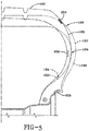
- FIG. 1 shows a preferred location for the air tube assembly 14.
- the tube 42 is located within a groove 126 in the sidewall 30 of the tire 12.
- the tube 42 as will be explained is closed by compression strain bending the sidewall groove 126 within a rolling tire footprint.
- the location of the tube 42 in the sidewall 30 affords the user freedom of placement and avoids contact between the tube 42 and the rim flange 16 at surface 26.
- the higher placement of the tube 42 in the sidewall groove 126 uses the deformation of the sidewall as it passes through the tire footprint to close the tube and provide the pumping action rather than pinching the tube.
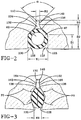
- the configuration and operation of the groove 126 to flatten the tube 42 is shown in FIGS. 2 and 3 .
- the groove 126 is defined by parallel entryway sidewalls 128, 130 at a groove entryway opening 132 having a nominal width W1.
- the width W1 is sufficient to closely admit the tube 42 with interference but without constricting the air passageway 43 extending through the tube 42.
- An interior generally triangular shaped groove portion 134 is defined between convergent groove sidewalls 136, 138.
- the sidewalls 136, 138 intersect entryway sidewalls 130, 128, respectively at an obtuse angle.
- the sidewalls 136, 138 converge inwardly at an angle ⁇ of approximately ninety degrees and contact the sides of the tube 42 in the position shown by FIG. 1 A.
- the sidewalls 136, 138 then converge inwardly to an inward U-shaped groove flex region 140 of a narrower width W2 defined between sidewalls 162, 164 as shown in FIG. 3 .
- the sidewalls 162, 164 intersect respectively sidewalls 136,138 at an obtuse angled junction designated by numerals 166, 168.
- the sidewalls 162, 166 extend to an inward radius end 142 of the U-shaped groove flex region 140. In the tube-expanded condition of FIG. 1A, the contact of surfaces 136, 138 and 128, 130 against the tube 42 is sufficient to hold the tube 42 within the groove 126.
- the location of the pump assembly 14 within the tire sidewall is distanced from the rim 16 as shown.
- a preferred location of the pump assembly tube 42 is within a groove 126 positioned in a generally axially extending chafer surface 144.
- the chafer 120 extends from the rim 16 and the location of the groove 126 within the surface 144 allows a separation of the tube 42 from the rim flange 24 while efficiently transferring tube closing forces from sidewall deformation to the tube 42.
- the tube 42 positioned within groove 126 is closed or flattened by compression due to tire sidewall 30 bending in the tire footprint 100.
- the force from the footprint imposes an axial directed force F2 into the sidewall 30 which acts to close the groove 126 from the open configuration of FIG. 2 to the closed configuration of FIG. 3 .
- the entryway opening 132 of the groove 126 constricts to a width dimension W2 and the groove sidewalls 128, 130 and 136, 138 are forced inward.
- Inward pressure from the sidewalls 128, 130 and 136, 138 against the tube 42 causes the affected segment of the tube 42 to flatten and thereby pump air evacuated therefrom along unaffected segments of the air passageway 43.
- Surfaces 128, 130 and 136, 138 extend from the narrower inward groove surfaces 162, 164 defining groove portion 134.
- Compression forces F2 act to close the groove 126 as surfaces 162, 164 and the respective surfaces 128, 130, 136, 138 extending therefrom pivot inwardly the radius end 142 of the groove portion 140.
- the compression forces F2 transferred into the tube 42 by the surfaces 128, 130, 136, 138 are distributed the circumference of the tube, causing an even and symmetrical flattening of the tube 42.
- An even and efficient pumping of evacuated air from the affected tube segment results.
- the affected segment of the tube 42 that is flattened is only that segment within the tire footprint. As the tire continues to rotate, each flattened segment will resume its original configuration as represented in FIG. 2 as an adjacent segment within the tire footprint is flattened.
- FIGS. 4 and 5 illustrate in schematic representation the placement of the groove and air tube within a tire.
- the sidewalls of a rolling tire generally bend and undergo a geometric transformation from bending strain introduced into the sidewalls as the tire rolls against a ground surface.
- the bending strain within sidewall regions adjacent to a tire footprint causes the radius of curvature within certain such sidewall regions of the sidewalls to bend to a greater extent.
- the region transforms from the unstrained configuration shown at 176 into the bending configuration shown at 178.
- the region 174 In the bending condition, the region 174 will have a neutral axis 180 that is not under strain; a compression side 182 of the neutral axis 180 of the region 174 that is under compression, and an elongation side of the neutral axis 180 of the region 174 that under elongation.
- a bending region of the sidewall is selected that will experience bending strain when that region is adjacent to the tire footprint.
- the compression side 182 of the region 174 is satisfactory for placement of the groove and tube assembly 188 since a compression of the side 182 of the region 174 will cause the groove to close around the air tube.
- the elongation side 184 of the region 174 is unsatisfactory for such a side under elongation strain, will cause the groove to widen rather than close, and not result in a flattening of the tube.
- Placement of the groove and tube assembly 188 should further be placed within the compression side 182 of the region 178 at a location farthest removed from the neutral axis 180, for such a location will experience the greatest compression strain.
- Location of the groove and tube 188 farthest from the neutral axis 180 of the selected bending region 174 will accordingly expose the groove to maximum closing due to a maximum compression force and bending imposed upon the tire region surrounding the groove.
- efficient and complete closing and collapse of the groove will be effected, causing an equally efficient and complete flattening of the air tube within the groove.
- FIG. 5 illustrates in schematic form three sidewall regions of a sidewall that undergo curvature bending transformation when adjacent to a tire footprint.
- the original tire shape 190 is shown and configuration 192 is superimposed to show tire deformation adjacent to a tire footprint.
- Three bending regions 194, 196, 198 are identified that will undergo strain-induced radius of curvature transformation adjacent a rolling tire footprint.
- Other regions are available and may be selected for groove and air tube placement if desired.
- bulging of the tire into the configuration 178 causes the regions 194, 196, 198 to bend to a greater extend (i.e. at a reduced radius) than within the original configuration 176.
- Each region 194, 196, 198 will have a neutral, unstrained axis, a compression side of the axis, and an elongation side of the axis as explained above in reference to FIG. 4 .
- a groove and tube assembly 200, 202, or 204 will be positioned to the compression side 182 of the region selected, so that the compression of the compression side 182 will act to bend and constrict a segment of the groove adjacent to the tire footprint. Bending and constriction of the groove segment adjacent the tire footprint will commensurately cause a bending and flattening of an air tube segment within the bending groove segment, whereby pumping evacuated air from the flattened air tube segment along the air tube passageway. Positioning the groove and air tube within a bending region of the sidewall thus operates to utilize the bending compression strain within the region to effect a bending and collapse of the groove segment within the bending region.
- Utilizing the bending strain within a bending region of a sidewall avoids the need to compress the air tube by pinching the air tube against a relatively hard barrier such as the tire assembly rim. Potential damage to the air tube from contact with the rim is thus avoided and the structural integrity of the air tube is preserved throughout the life cycle of the tire.
- the tube may experience cracking due to excess stress and strain due to the repetitive bending. Further, the internal surfaces of the tube may rub during flexure causing abrasion and blockage of the tube. Such cracking and internal abrasion may lead to reduce pumping efficiency for the peristaltic tube. To reduce the likelihood of cracking and abrasion in the tube, the tube is extruded from a rubber composition as further described.
- the tube 42 is extruded from a rubber composition.
- the rubber composition includes a self-lubrication agent capable of migrating from the rubber composition to the groove surface and disposing on the groove surface as a liquid.
- self-lubricating it is meant that the self-lubrication agent will migrate by diffusion or otherwise from the bulk of the rubber composition to the groove surface, whereon the agent exists in liquid form to act as a lubricant to reduce the likelihood of cracking in the groove surface.
- Self-lubricating agents that may solidify at the surface are not usable, as the formation of the solid may cause blockage of the air passageway.
- Suitable self-lubrication agents include liquids having a melting points of less than 0 °C. In one embodiment, the self-lubrication agents has a melting points of less than -10 °C. Melting point may be determined by methods as are known in the art, including ASTM D5440-93.
- the self-lubrication agent may include an oil.
- Suitable oils include, paraffinic, and vegetable oils.
- Suitable vegetable oils include canola (rapeseed) oil, sunflower oil, soybean oil, castor oil, and the like.
- the rubber composition includes from 0.25 to 5 phr of the self-lubrication agent. In another embodiment, the rubber composition includes from 0.5 to 1.5 phr of the self-lubrication agent.
- the rubber composition includes a vulcanization modifier.
- the vulcanization modifier for use in the second rubber composition one include or more of a, ⁇ -bis(N,N'-dihydrocarbylthiocarbamamoyldithio)alkanes, bismaleimides, and biscitraconimides.
- the vulcanization modifier is a ⁇ , ⁇ -bis(N,N'-dihydrocarbylthiocarbamamoyldithio)alkanes.
- Suitable ⁇ , ⁇ -bis(N,N'-dihydrocarbylthiocarbamamoyldithio)alkanes include 1,2-bis(N,N'-dibenzylthiocarbamoyl-dithio)ethane; 1,3-bis(N,N'-dibenzylthiocarbamoyldithio)propane; 1,4-bis(N,N'-dibenzylth-iocarbamoyldithio)butane; 1,5-bis(N,N'-dibenzylthiocarbamoyl-dithio)pentane; 1,6-bis(N,N'-dibenzylthiocarbamoyldithio)hexane;
- the vulcanization modifier is a bismaleimide.
- Suitable bismaleimides include N, N'-m-phenylene bismaleimide, available as HVA-2 from DuPont.
- the vulcanization modifier is a citraconimide.
- Suitable citraconimidies include N, N'-m-xylylene biscitraconimide, also known as1,3-bis(citraconimidomethyl)benzene, available as Perkalink® 900 from Flexsys.
- the rubber composition in one or more annular segments comprises from 1 to 15 parts by weight, per 100 parts by weight of elastomer (phr), of the vulcanization modifier. In another embodiment, the rubber composition comprises from 2 to 8 phr of vulcanization modifier.
- the rubber composition includes one or more rubbers or elastomers containing olefinic unsaturation.
- the phrases "rubber or elastomer containing olefinic unsaturation” or “diene based elastomer” are intended to include both natural rubber and its various raw and reclaim forms as well as various synthetic rubbers.
- the terms “rubber” and “elastomer” may be used interchangeably, unless otherwise prescribed.
- the terms “rubber composition,” “compounded rubber” and “rubber compound” are used interchangeably to refer to rubber which has been blended or mixed with various ingredients and materials and such terms are well known to those having skill in the rubber mixing or rubber compounding art.
- Representative synthetic polymers are the homopolymerization products of butadiene and its homologues and derivatives, for example, methylbutadiene, dimethylbutadiene and pentadiene as well as copolymers such as those formed from butadiene or its homologues or derivatives with other unsaturated monomers.
- acetylenes for example, vinyl acetylene
- olefins for example, isobutylene, which copolymerizes with isoprene to form butyl rubber
- vinyl compounds for example, acrylic acid, acrylonitrile (which polymerize with butadiene to form NBR), methacrylic acid and styrene, the latter compound polymerizing with butadiene to form SBR, as well as vinyl esters and various unsaturated aldehydes, ketones and ethers, e.g., acrolein, methyl isopropenyl ketone and vinylethyl ether.
- synthetic rubbers include neoprene (polychloroprene), polybutadiene (including cis-1,4-polybutadiene), polyisoprene (including cis-1,4-polyisoprene), butyl rubber, halobutyl rubber such as chlorobutyl rubber or bromobutyl rubber, styrene/isoprene/butadiene rubber, copolymers of 1,3-butadiene or isoprene with monomers such as styrene, acrylonitrile and methyl methacrylate, as well as ethylene/propylene terpolymers, also known as ethylene/propylene/diene monomer (EPDM), and in particular, ethylene/propylene/ dicyclopentadiene terpolymers.
- neoprene polychloroprene
- polybutadiene including cis-1,4-polybutadiene
- rubbers which may be used include alkoxy-silyl end functionalized solution polymerized polymers (SBR, PBR, IBR and SIBR), silicon-coupled and tin-coupled star-branched polymers.
- SBR alkoxy-silyl end functionalized solution polymerized polymers
- PBR polybutadiene
- SIBR silicon-coupled and tin-coupled star-branched polymers.
- the preferred rubber or elastomers are polyisoprene (natural or synthetic), polybutadiene and SBR.
- the at least one additional rubber is preferably of at least two of diene based rubbers.
- a combination of two or more rubbers is preferred such as cis 1,4-polyisoprene rubber (natural or synthetic, although natural is preferred), 3,4-polyisoprene rubber, styrene/isoprene/butadiene rubber, emulsion and solution polymerization derived styrene/butadiene rubbers, cis 1,4-polybutadiene rubbers and emulsion polymerization prepared butadiene/acrylonitrile copolymers.
- an emulsion polymerization derived styrene/butadiene might be used having a relatively conventional styrene content of 20 to 28 percent bound styrene or, for some applications, an E-SBR having a medium to relatively high bound styrene content, namely, a bound styrene content of 30 to 45 percent.
- E-SBR emulsion polymerization prepared E-SBR
- styrene and 1,3-butadiene are copolymerized as an aqueous emulsion.
- the bound styrene content can vary, for example, from 5 to 50 percent.
- the E-SBR may also contain acrylonitrile to form a terpolymer rubber, as E-SBAR, in amounts, for example, of 2 to 30 weight percent bound acrylonitrile in the terpolymer.
- Emulsion polymerization prepared styrene/butadiene/acrylonitrile copolymer rubbers containing 2 to 40 weight percent bound acrylonitrile in the copolymer are also contemplated as diene based rubbers for use in this invention.
- S-SBR solution polymerization prepared SBR
- S-SBR typically has a bound styrene content in a range of 5 to 50, preferably 9 to 36, percent.
- the S-SBR can be conveniently prepared, for example, by organo lithium catalyzation in the presence of an organic hydrocarbon solvent.
- cis 1,4-polybutadiene rubber may be used.
- BR cis 1,4-polybutadiene rubber
- Such BR can be prepared, for example, by organic solution polymerization of 1,3-butadiene.
- the BR may be conveniently characterized, for example, by having at least a 90 percent cis 1,4-content.
- the rubber composition may also include up to 70 phr of processing oil.
- Processing oil may be included in the rubber composition as extending oil typically used to extend elastomers. Processing oil may also be included in the rubber composition by addition of the oil directly during rubber compounding.
- the processing oil used may include both extending oil present in the elastomers, and process oil added during compounding.
- Suitable process oils include various oils as are known in the art, including aromatic, paraffinic, naphthenic, vegetable oils, and low PCA oils, such as MES, TDAE, SRAE and heavy naphthenic oils.
- Suitable low PCA oils include those having a polycyclic aromatic content of less than 3 percent by weight as determined by the IP346 method. Procedures for the IP346 method may be found in Standard Methods for Analysis & Testing of Petroleum and Related Products and British Standard 2000 Parts, 2003, 62nd edition, published by the Institute of Petroleum, United Kingdom .
- the rubber composition may include from 10 to 150 phr of silica. In another embodiment, from 20 to 80 phr of silica may be used.
- the commonly employed siliceous pigments which may be used in the rubber compound include conventional pyrogenic and precipitated siliceous pigments (silica).
- precipitated silica is used.
- the conventional siliceous pigments employed in this invention are precipitated silicas such as, for example, those obtained by the acidification of a soluble silicate, e.g., sodium silicate.
- Such conventional silicas might be characterized, for example, by having a BET surface area, as measured using nitrogen gas.
- the BET surface area may be in the range of 40 to 600 square meters per gram. In another embodiment, the BET surface area may be in a range of 80 to 300 square meters per gram. The BET method of measuring surface area is described in the Journal of the American Chemical Society, Volume 60, Page 304 (1930 ).
- the conventional silica may also be characterized by having a dibutylphthalate (DBP) absorption value in a range of 100 to 400, alternatively 150 to 300.
- DBP dibutylphthalate
- the conventional silica might be expected to have an average ultimate particle size, for example, in the range of 0.01 to 0.05 micron as determined by the electron microscope, although the silica particles may be even smaller, or possibly larger, in size.
- silicas such as, only for example herein, and without limitation, silicas commercially available from PPG Industries under the Hi-Sil trademark with designations 210 and 243, silicas available from Rhodia, with, for example, designations of Z1165MP and Z165GR, and silicas available from Degussa AG with, for example, designations VN2 and VN3.
- Commonly employed carbon blacks can be used as a conventional filler in an amount ranging from 10 to 150 phr. In another embodiment, from 20 to 80 phr of carbon black may be used.
- Representative examples of such carbon blacks include N110, N121, N134, N220, N231, N234, N242, N293, N299, N315, N326, N330, N332, N339, N343, N347, N351, N358, N375, N539, N550, N582, N630, N642, N650, N683, N754, N762, N765, N774, N787, N907, N908, N990 and N991.
- These carbon blacks have iodine absorptions ranging from 9 to 145 g/kg and DBP number ranging from 34 to 150 cm 3 /100 g.
- fillers may be used in the rubber composition including, but not limited to, particulate fillers including ultra high molecular weight polyethylene (UHMWPE) and plasticized starch omposite filler. Such other fillers may be used in an amount ranging from 1 to 30 phr.
- UHMWPE ultra high molecular weight polyethylene
- plasticized starch omposite filler plasticized starch omposite filler.
- the rubber composition may contain a conventional sulfur containing organosilicon compound.
- the sulfur containing organosilicon compounds are the 3,3'-bis(trimethoxy or triethoxy silylpropyl) polysulfides.
- the sulfur containing organosilicon compounds are 3,3'-bis(triethoxysilylpropyl) disulfide and/or 3,3'-bis(triethoxysilylpropyl) tetrasulfide.
- suitable sulfur containing organosilicon compounds include compounds disclosed in U.S. Patent No. 6,608,125 .
- suitable sulfur containing organosilicon compounds include those disclosed in US-A- 2003/0130535 .
- the sulfur containing organosilicon compound is Si-363 from Degussa.
- the amount of the sulfur containing organosilicon compound in a rubber composition will vary depending on the level of other additives that are used. Generally speaking, the amount of the compound will range from 0.5 to 20 phr. In one embodiment, the amount will range from 1 to 10 phr.
- the rubber composition would be compounded by methods generally known in the rubber compounding art, such as mixing the various sulfur-vulcanizable constituent rubbers with various commonly used additive materials such as, for example, sulfur donors, curing aids, such as activators and retarders and processing additives, such as oils, resins including tackifying resins and plasticizers, fillers, pigments, fatty acid, zinc oxide, waxes, antioxidants and antiozonants and peptizing agents.
- additives mentioned above are selected and commonly used in conventional amounts.
- sulfur donors include elemental sulfur (free sulfur), an amine disulfide, polymeric polysulfide and sulfur olefin adducts.
- the sulfur-vulcanizing agent is elemental sulfur.
- the sulfur-vulcanizing agent may be used in an amount ranging from 0.5 to 8 phr, alternatively with a range of from 1.5 to 6 phr.
- Typical amounts of tackifier resins, if used, comprise 0.5 to 10 phr, usually 1 to 5 phr.
- processing aids comprise 1 to 50 phr.
- Typical amounts of antioxidants comprise 1 to 5 phr.
- antioxidants may be, for example, diphenyl-p-phenylenediamine and others, such as, for example, those disclosed in The Vanderbilt Rubber Handbook (1978), Pages 344 through 346 .
- Typical amounts of antiozonants comprise 1 to 5 phr.
- Typical amounts of fatty acids, if used, which can include stearic acid comprise 0.5 to 3 phr.
- Typical amounts of zinc oxide comprise 2 to 5 phr.
- Typical amounts of waxes comprise 1 to 5 phr. Often microcrystalline waxes are used.
- peptizers comprise 0.1 to 1 phr.
- Typical peptizers may be, for example, pentachlorothiophenol and dibenzamidodiphenyl disulfide.
- Accelerators are used to control the time and/or temperature required for vulcanization and to improve the properties of the vulcanizate.
- a single accelerator system may be used, i.e., primary accelerator.
- the primary accelerator(s) may be used in total amounts ranging from 0.5 to 4, alternatively 0.8 to 1.5, phr.
- combinations of a primary and a secondary accelerator might be used with the secondary accelerator being used in smaller amounts, such as from 0.05 to 3 phr, in order to activate and to improve the properties of the vulcanizate. Combinations of these accelerators might be expected to produce a synergistic effect on the final properties and are somewhat better than those produced by use of either accelerator alone.
- delayed action accelerators may be used which are not affected by normal processing temperatures but produce a satisfactory cure at ordinary vulcanization temperatures.
- Vulcanization retarders might also be used.
- Suitable types of accelerators that may be used in the present invention are amines, disulfides, guanidines, thioureas, thiazoles, thiurams, sulfenamides, dithiocarbamates and xanthates.
- the primary accelerator is a sulfenamide. If a second accelerator is used, the secondary accelerator may be a guanidine, dithiocarbamate or thiuram compound.
- the mixing of the rubber composition can be accomplished by methods known to those having skill in the rubber mixing art.
- the ingredients are typically mixed in at least two stages, namely, at least one non-productive stage followed by a productive mix stage.
- the final curatives including sulfur-vulcanizing agents are typically mixed in the final stage which is conventionally called the "productive" mix stage in which the mixing typically occurs at a temperature, or ultimate temperature, lower than the mix temperature(s) than the preceding non-productive mix stage(s).
- the rubber composition may be subjected to a thermomechanical mixing step.
- the thermomechanical mixing step generally comprises a mechanical working in a mixer or extruder for a period of time suitable in order to produce a rubber temperature between 140°C and 190°C.
- the appropriate duration of the thermomechanical working varies as a function of the operating conditions, and the volume and nature of the components.
- the thermomechanical working may be from 1 to 20 minutes.
- the air tube 42 may be extruded from the rubber composition using extrusion procedures as are known in the art.
- Vulcanization of the pneumatic tire of the present invention is generally carried out at conventional temperatures ranging from 100°C to 200°C. In one embodiment, the vulcanization is conducted at temperatures ranging from 110°C to 180°C. Any of the usual vulcanization processes may be used such as heating in a press or mold, heating with superheated steam or hot air. Such tires can be built, shaped, molded and cured by various methods which are known and will be readily apparent to those having skill in such art.
Landscapes
- Chemical & Material Sciences (AREA)
- Health & Medical Sciences (AREA)
- Chemical Kinetics & Catalysis (AREA)
- Medicinal Chemistry (AREA)
- Polymers & Plastics (AREA)
- Organic Chemistry (AREA)
- Engineering & Computer Science (AREA)
- Mechanical Engineering (AREA)
- Compositions Of Macromolecular Compounds (AREA)
- Tires In General (AREA)
Applications Claiming Priority (2)
| Application Number | Priority Date | Filing Date | Title |
|---|---|---|---|
| US201662288658P | 2016-01-29 | 2016-01-29 | |
| US15/416,138 US20170217263A1 (en) | 2016-01-29 | 2017-01-26 | Air maintenance tire |
Publications (2)
| Publication Number | Publication Date |
|---|---|
| EP3199585A1 true EP3199585A1 (de) | 2017-08-02 |
| EP3199585B1 EP3199585B1 (de) | 2018-11-21 |
Family
ID=57909516
Family Applications (1)
| Application Number | Title | Priority Date | Filing Date |
|---|---|---|---|
| EP17153449.8A Active EP3199585B1 (de) | 2016-01-29 | 2017-01-27 | Rohr und luftwartungsreifen mit solch einem rohr |
Country Status (2)
| Country | Link |
|---|---|
| US (2) | US20170217263A1 (de) |
| EP (1) | EP3199585B1 (de) |
Families Citing this family (1)
| Publication number | Priority date | Publication date | Assignee | Title |
|---|---|---|---|---|
| US20170217263A1 (en) | 2016-01-29 | 2017-08-03 | The Goodyear Tire & Rubber Company | Air maintenance tire |
Citations (9)
| Publication number | Priority date | Publication date | Assignee | Title |
|---|---|---|---|---|
| EP0703943A1 (de) * | 1993-06-14 | 1996-04-03 | Akzo Nobel N.V. | Polysulfidharze in vulkanisierten kautschukmischungen |
| US20030130535A1 (en) | 2001-08-06 | 2003-07-10 | Degussa Ag, | Organosilicon compounds |
| US6608125B2 (en) | 1997-08-21 | 2003-08-19 | Crompton Corporation | Blocked mercaptosilane coupling agents for filled rubbers |
| US20030221760A1 (en) * | 2000-07-31 | 2003-12-04 | Bruno Grimberg | Metal/rubber composite for tire |
| US20040079462A1 (en) * | 1999-12-28 | 2004-04-29 | Tracey Donald Sheley | Inner tube compositions having improved heat resistance characteristics |
| EP1674292A1 (de) * | 2004-12-22 | 2006-06-28 | The Goodyear Tire & Rubber Company | Gummizusammensetzung enthaltend Organothiosulfate und Bismaleimide |
| US8042586B2 (en) | 2009-12-21 | 2011-10-25 | The Goodyear Tire & Rubber Company | Self-inflating tire assembly |
| US20150165842A1 (en) * | 2013-12-13 | 2015-06-18 | The Goodyear Tire & Rubber Company | Air maintenance tire |
| US20150165843A1 (en) * | 2013-12-13 | 2015-06-18 | The Goodyear Tire & Rubber Company | Air maintenance tire |
Family Cites Families (18)
| Publication number | Priority date | Publication date | Assignee | Title |
|---|---|---|---|---|
| JPS54141838A (en) * | 1978-04-25 | 1979-11-05 | Mitsui Toatsu Chem Inc | Styrene resin composition |
| DE4220563A1 (de) | 1992-06-24 | 1994-01-13 | Bayer Ag | Kautschukmischungen enthaltend Polybutadien-Gel |
| TW273561B (de) * | 1993-10-21 | 1996-04-01 | Sumitomo Bakelite Co | |
| US5672639A (en) | 1996-03-12 | 1997-09-30 | The Goodyear Tire & Rubber Company | Starch composite reinforced rubber composition and tire with at least one component thereof |
| DE19701488A1 (de) | 1997-01-17 | 1998-07-23 | Bayer Ag | SBR-Kautschukgele enthaltende Kautschukmischungen |
| DE19834802A1 (de) | 1998-08-01 | 2000-02-03 | Continental Ag | Kautschukmischung |
| DE19834804A1 (de) | 1998-08-01 | 2000-02-03 | Continental Ag | Kautschukmischung |
| DE19834803A1 (de) | 1998-08-01 | 2000-02-03 | Continental Ag | Kautschukmischung |
| DE19942620A1 (de) * | 1999-09-07 | 2001-03-08 | Bayer Ag | Mikrogelhaltige Kautschukmischungen mit verkappten bifunktionellen Mercaptanen und hieraus hergestellte Vulkanisate |
| US7015272B2 (en) * | 2002-10-28 | 2006-03-21 | The Goodyear Tire & Rubber Company | Rubber with polyethylene and phenylene bismaleimide and tire with component thereof |
| JP4595488B2 (ja) * | 2003-12-09 | 2010-12-08 | 東海ゴム工業株式会社 | 防振ゴム組成物 |
| US7694708B2 (en) * | 2006-10-10 | 2010-04-13 | The Goodyear Tire & Rubber Company | Tire with sidewall insert |
| WO2012165561A1 (ja) * | 2011-06-01 | 2012-12-06 | 株式会社ブリヂストン | 防振ゴム組成物及び防振ゴム |
| US8381784B2 (en) * | 2011-07-08 | 2013-02-26 | The Goodyear Tire & Rubber Company | Air maintenance pumping assembly and tire |
| US9056533B2 (en) * | 2012-05-14 | 2015-06-16 | The Goodyear Tire & Rubber Company | Peristaltic tube air maintenance tire assembly and method |
| US9259975B2 (en) * | 2013-03-15 | 2016-02-16 | The Goodyear Tire & Rubber Company | Tire with outer groove containing bonded tube |
| US20170217263A1 (en) | 2016-01-29 | 2017-08-03 | The Goodyear Tire & Rubber Company | Air maintenance tire |
| US10449813B2 (en) * | 2016-01-29 | 2019-10-22 | The Goodyear Tire & Rubber Company | Air maintenance tire |
-
2017
- 2017-01-26 US US15/416,138 patent/US20170217263A1/en not_active Abandoned
- 2017-01-27 EP EP17153449.8A patent/EP3199585B1/de active Active
-
2019
- 2019-09-04 US US16/560,034 patent/US11981169B2/en active Active
Patent Citations (9)
| Publication number | Priority date | Publication date | Assignee | Title |
|---|---|---|---|---|
| EP0703943A1 (de) * | 1993-06-14 | 1996-04-03 | Akzo Nobel N.V. | Polysulfidharze in vulkanisierten kautschukmischungen |
| US6608125B2 (en) | 1997-08-21 | 2003-08-19 | Crompton Corporation | Blocked mercaptosilane coupling agents for filled rubbers |
| US20040079462A1 (en) * | 1999-12-28 | 2004-04-29 | Tracey Donald Sheley | Inner tube compositions having improved heat resistance characteristics |
| US20030221760A1 (en) * | 2000-07-31 | 2003-12-04 | Bruno Grimberg | Metal/rubber composite for tire |
| US20030130535A1 (en) | 2001-08-06 | 2003-07-10 | Degussa Ag, | Organosilicon compounds |
| EP1674292A1 (de) * | 2004-12-22 | 2006-06-28 | The Goodyear Tire & Rubber Company | Gummizusammensetzung enthaltend Organothiosulfate und Bismaleimide |
| US8042586B2 (en) | 2009-12-21 | 2011-10-25 | The Goodyear Tire & Rubber Company | Self-inflating tire assembly |
| US20150165842A1 (en) * | 2013-12-13 | 2015-06-18 | The Goodyear Tire & Rubber Company | Air maintenance tire |
| US20150165843A1 (en) * | 2013-12-13 | 2015-06-18 | The Goodyear Tire & Rubber Company | Air maintenance tire |
Non-Patent Citations (3)
| Title |
|---|
| "Standard Methods for Analysis & Testing of Petroleum and Related Products and British Standard 2000", 2003, INSTITUTE OF PETROLEUM |
| "The Vanderbilt Rubber Handbook", 1978, pages: 344 - 346 |
| JOURNAL OF THE AMERICAN CHEMICAL SOCIETY, vol. 60, 1930, pages 304 |
Also Published As
| Publication number | Publication date |
|---|---|
| EP3199585B1 (de) | 2018-11-21 |
| US20200009927A1 (en) | 2020-01-09 |
| US20170217263A1 (en) | 2017-08-03 |
| US11981169B2 (en) | 2024-05-14 |
Similar Documents
| Publication | Publication Date | Title |
|---|---|---|
| US9809067B2 (en) | Air maintenance tire | |
| EP2338697B1 (de) | Reifen mit Komponente aus Kohlennanoröhrchen | |
| EP2329965B1 (de) | Luftreifen | |
| EP1911608B1 (de) | Reifen mit Seitenwandeinsatz | |
| US8701727B2 (en) | Truck drive tire | |
| EP2028021B1 (de) | Reifen mit Komponente mit Kombinationsweichmacher | |
| US9809068B2 (en) | Air maintenance tire | |
| US11851549B2 (en) | Tire | |
| US20090156740A1 (en) | Tire with component containing polymeric nanofiber | |
| EP2199114B1 (de) | Reifen mit Wulststoff | |
| EP2030809B1 (de) | Reifen mit asphaltenhaltiger Komponente | |
| EP2380757A2 (de) | Luftreifen mit Fasern aufweisender Lauffläche | |
| EP2982525B1 (de) | Reifen mit pneumatischer wartung | |
| US11981169B2 (en) | Air maintenance tire | |
| EP4183595B1 (de) | Reifen mit verbessertem schulterdesign | |
| US20130160931A1 (en) | Method of providing an air passage in a tire | |
| EP4159808A1 (de) | Kautschukzusammensetzung und reifen | |
| US7441575B2 (en) | Tire with component having nanozeolite | |
| EP3831873B1 (de) | Kautschukzusammensetzung und fertigungsgegenstand mit der kautschukzusammensetzung | |
| EP3199582B1 (de) | Reifen mit pneumatischer wartung |
Legal Events
| Date | Code | Title | Description |
|---|---|---|---|
| PUAI | Public reference made under article 153(3) epc to a published international application that has entered the european phase |
Free format text: ORIGINAL CODE: 0009012 |
|
| STAA | Information on the status of an ep patent application or granted ep patent |
Free format text: STATUS: THE APPLICATION HAS BEEN PUBLISHED |
|
| AK | Designated contracting states |
Kind code of ref document: A1 Designated state(s): AL AT BE BG CH CY CZ DE DK EE ES FI FR GB GR HR HU IE IS IT LI LT LU LV MC MK MT NL NO PL PT RO RS SE SI SK SM TR |
|
| AX | Request for extension of the european patent |
Extension state: BA ME |
|
| STAA | Information on the status of an ep patent application or granted ep patent |
Free format text: STATUS: REQUEST FOR EXAMINATION WAS MADE |
|
| 17P | Request for examination filed |
Effective date: 20180202 |
|
| RBV | Designated contracting states (corrected) |
Designated state(s): AL AT BE BG CH CY CZ DE DK EE ES FI FR GB GR HR HU IE IS IT LI LT LU LV MC MK MT NL NO PL PT RO RS SE SI SK SM TR |
|
| GRAP | Despatch of communication of intention to grant a patent |
Free format text: ORIGINAL CODE: EPIDOSNIGR1 |
|
| RIC1 | Information provided on ipc code assigned before grant |
Ipc: C08L 21/02 20060101AFI20180504BHEP Ipc: C08L 9/00 20060101ALI20180504BHEP Ipc: C08L 7/00 20060101ALI20180504BHEP Ipc: C08K 5/00 20060101ALI20180504BHEP Ipc: B60C 23/12 20060101ALI20180504BHEP Ipc: C08L 9/06 20060101ALI20180504BHEP Ipc: B60C 1/00 20060101ALI20180504BHEP Ipc: B60C 13/02 20060101ALI20180504BHEP |
|
| STAA | Information on the status of an ep patent application or granted ep patent |
Free format text: STATUS: GRANT OF PATENT IS INTENDED |
|
| INTG | Intention to grant announced |
Effective date: 20180614 |
|
| RIN1 | Information on inventor provided before grant (corrected) |
Inventor name: VOJTKO, DANIEL Inventor name: WELTER, CAROLIN ANNA Inventor name: DU, MINGLIANG Inventor name: RODEWALD, STEPHAN Inventor name: PERONNET-PAQUIN, ANNE THERESE Inventor name: KANG, JUNGMEE Inventor name: BUEHLER, BETUL Inventor name: FRANTZEN, ANDREAS Inventor name: GARN, BENJAMIN ISAIAH Inventor name: CHANDRA, DINESH |
|
| GRAS | Grant fee paid |
Free format text: ORIGINAL CODE: EPIDOSNIGR3 |
|
| GRAA | (expected) grant |
Free format text: ORIGINAL CODE: 0009210 |
|
| STAA | Information on the status of an ep patent application or granted ep patent |
Free format text: STATUS: THE PATENT HAS BEEN GRANTED |
|
| AK | Designated contracting states |
Kind code of ref document: B1 Designated state(s): AL AT BE BG CH CY CZ DE DK EE ES FI FR GB GR HR HU IE IS IT LI LT LU LV MC MK MT NL NO PL PT RO RS SE SI SK SM TR |
|
| REG | Reference to a national code |
Ref country code: CH Ref legal event code: EP |
|
| REG | Reference to a national code |
Ref country code: IE Ref legal event code: FG4D |
|
| REG | Reference to a national code |
Ref country code: DE Ref legal event code: R096 Ref document number: 602017000915 Country of ref document: DE |
|
| REG | Reference to a national code |
Ref country code: AT Ref legal event code: REF Ref document number: 1067459 Country of ref document: AT Kind code of ref document: T Effective date: 20181215 |
|
| REG | Reference to a national code |
Ref country code: NL Ref legal event code: MP Effective date: 20181121 |
|
| REG | Reference to a national code |
Ref country code: AT Ref legal event code: MK05 Ref document number: 1067459 Country of ref document: AT Kind code of ref document: T Effective date: 20181121 |
|
| PG25 | Lapsed in a contracting state [announced via postgrant information from national office to epo] |
Ref country code: AT Free format text: LAPSE BECAUSE OF FAILURE TO SUBMIT A TRANSLATION OF THE DESCRIPTION OR TO PAY THE FEE WITHIN THE PRESCRIBED TIME-LIMIT Effective date: 20181121 Ref country code: IS Free format text: LAPSE BECAUSE OF FAILURE TO SUBMIT A TRANSLATION OF THE DESCRIPTION OR TO PAY THE FEE WITHIN THE PRESCRIBED TIME-LIMIT Effective date: 20190321 Ref country code: LT Free format text: LAPSE BECAUSE OF FAILURE TO SUBMIT A TRANSLATION OF THE DESCRIPTION OR TO PAY THE FEE WITHIN THE PRESCRIBED TIME-LIMIT Effective date: 20181121 Ref country code: NO Free format text: LAPSE BECAUSE OF FAILURE TO SUBMIT A TRANSLATION OF THE DESCRIPTION OR TO PAY THE FEE WITHIN THE PRESCRIBED TIME-LIMIT Effective date: 20190221 Ref country code: LV Free format text: LAPSE BECAUSE OF FAILURE TO SUBMIT A TRANSLATION OF THE DESCRIPTION OR TO PAY THE FEE WITHIN THE PRESCRIBED TIME-LIMIT Effective date: 20181121 Ref country code: HR Free format text: LAPSE BECAUSE OF FAILURE TO SUBMIT A TRANSLATION OF THE DESCRIPTION OR TO PAY THE FEE WITHIN THE PRESCRIBED TIME-LIMIT Effective date: 20181121 Ref country code: BG Free format text: LAPSE BECAUSE OF FAILURE TO SUBMIT A TRANSLATION OF THE DESCRIPTION OR TO PAY THE FEE WITHIN THE PRESCRIBED TIME-LIMIT Effective date: 20190221 Ref country code: ES Free format text: LAPSE BECAUSE OF FAILURE TO SUBMIT A TRANSLATION OF THE DESCRIPTION OR TO PAY THE FEE WITHIN THE PRESCRIBED TIME-LIMIT Effective date: 20181121 Ref country code: FI Free format text: LAPSE BECAUSE OF FAILURE TO SUBMIT A TRANSLATION OF THE DESCRIPTION OR TO PAY THE FEE WITHIN THE PRESCRIBED TIME-LIMIT Effective date: 20181121 |
|
| PG25 | Lapsed in a contracting state [announced via postgrant information from national office to epo] |
Ref country code: SE Free format text: LAPSE BECAUSE OF FAILURE TO SUBMIT A TRANSLATION OF THE DESCRIPTION OR TO PAY THE FEE WITHIN THE PRESCRIBED TIME-LIMIT Effective date: 20181121 Ref country code: GR Free format text: LAPSE BECAUSE OF FAILURE TO SUBMIT A TRANSLATION OF THE DESCRIPTION OR TO PAY THE FEE WITHIN THE PRESCRIBED TIME-LIMIT Effective date: 20190222 Ref country code: RS Free format text: LAPSE BECAUSE OF FAILURE TO SUBMIT A TRANSLATION OF THE DESCRIPTION OR TO PAY THE FEE WITHIN THE PRESCRIBED TIME-LIMIT Effective date: 20181121 Ref country code: NL Free format text: LAPSE BECAUSE OF FAILURE TO SUBMIT A TRANSLATION OF THE DESCRIPTION OR TO PAY THE FEE WITHIN THE PRESCRIBED TIME-LIMIT Effective date: 20181121 Ref country code: PT Free format text: LAPSE BECAUSE OF FAILURE TO SUBMIT A TRANSLATION OF THE DESCRIPTION OR TO PAY THE FEE WITHIN THE PRESCRIBED TIME-LIMIT Effective date: 20190321 Ref country code: AL Free format text: LAPSE BECAUSE OF FAILURE TO SUBMIT A TRANSLATION OF THE DESCRIPTION OR TO PAY THE FEE WITHIN THE PRESCRIBED TIME-LIMIT Effective date: 20181121 |
|
| PG25 | Lapsed in a contracting state [announced via postgrant information from national office to epo] |
Ref country code: DK Free format text: LAPSE BECAUSE OF FAILURE TO SUBMIT A TRANSLATION OF THE DESCRIPTION OR TO PAY THE FEE WITHIN THE PRESCRIBED TIME-LIMIT Effective date: 20181121 Ref country code: PL Free format text: LAPSE BECAUSE OF FAILURE TO SUBMIT A TRANSLATION OF THE DESCRIPTION OR TO PAY THE FEE WITHIN THE PRESCRIBED TIME-LIMIT Effective date: 20181121 Ref country code: CZ Free format text: LAPSE BECAUSE OF FAILURE TO SUBMIT A TRANSLATION OF THE DESCRIPTION OR TO PAY THE FEE WITHIN THE PRESCRIBED TIME-LIMIT Effective date: 20181121 |
|
| REG | Reference to a national code |
Ref country code: DE Ref legal event code: R097 Ref document number: 602017000915 Country of ref document: DE |
|
| PG25 | Lapsed in a contracting state [announced via postgrant information from national office to epo] |
Ref country code: RO Free format text: LAPSE BECAUSE OF FAILURE TO SUBMIT A TRANSLATION OF THE DESCRIPTION OR TO PAY THE FEE WITHIN THE PRESCRIBED TIME-LIMIT Effective date: 20181121 Ref country code: MC Free format text: LAPSE BECAUSE OF FAILURE TO SUBMIT A TRANSLATION OF THE DESCRIPTION OR TO PAY THE FEE WITHIN THE PRESCRIBED TIME-LIMIT Effective date: 20181121 Ref country code: SK Free format text: LAPSE BECAUSE OF FAILURE TO SUBMIT A TRANSLATION OF THE DESCRIPTION OR TO PAY THE FEE WITHIN THE PRESCRIBED TIME-LIMIT Effective date: 20181121 Ref country code: EE Free format text: LAPSE BECAUSE OF FAILURE TO SUBMIT A TRANSLATION OF THE DESCRIPTION OR TO PAY THE FEE WITHIN THE PRESCRIBED TIME-LIMIT Effective date: 20181121 Ref country code: SM Free format text: LAPSE BECAUSE OF FAILURE TO SUBMIT A TRANSLATION OF THE DESCRIPTION OR TO PAY THE FEE WITHIN THE PRESCRIBED TIME-LIMIT Effective date: 20181121 |
|
| PLBE | No opposition filed within time limit |
Free format text: ORIGINAL CODE: 0009261 |
|
| STAA | Information on the status of an ep patent application or granted ep patent |
Free format text: STATUS: NO OPPOSITION FILED WITHIN TIME LIMIT |
|
| PG25 | Lapsed in a contracting state [announced via postgrant information from national office to epo] |
Ref country code: LU Free format text: LAPSE BECAUSE OF NON-PAYMENT OF DUE FEES Effective date: 20190127 |
|
| REG | Reference to a national code |
Ref country code: BE Ref legal event code: MM Effective date: 20190131 |
|
| 26N | No opposition filed |
Effective date: 20190822 |
|
| REG | Reference to a national code |
Ref country code: IE Ref legal event code: MM4A |
|
| PG25 | Lapsed in a contracting state [announced via postgrant information from national office to epo] |
Ref country code: SI Free format text: LAPSE BECAUSE OF FAILURE TO SUBMIT A TRANSLATION OF THE DESCRIPTION OR TO PAY THE FEE WITHIN THE PRESCRIBED TIME-LIMIT Effective date: 20181121 |
|
| PG25 | Lapsed in a contracting state [announced via postgrant information from national office to epo] |
Ref country code: BE Free format text: LAPSE BECAUSE OF NON-PAYMENT OF DUE FEES Effective date: 20190131 |
|
| PG25 | Lapsed in a contracting state [announced via postgrant information from national office to epo] |
Ref country code: IE Free format text: LAPSE BECAUSE OF NON-PAYMENT OF DUE FEES Effective date: 20190127 |
|
| PG25 | Lapsed in a contracting state [announced via postgrant information from national office to epo] |
Ref country code: TR Free format text: LAPSE BECAUSE OF FAILURE TO SUBMIT A TRANSLATION OF THE DESCRIPTION OR TO PAY THE FEE WITHIN THE PRESCRIBED TIME-LIMIT Effective date: 20181121 |
|
| PG25 | Lapsed in a contracting state [announced via postgrant information from national office to epo] |
Ref country code: MT Free format text: LAPSE BECAUSE OF NON-PAYMENT OF DUE FEES Effective date: 20190127 |
|
| REG | Reference to a national code |
Ref country code: CH Ref legal event code: PL |
|
| PG25 | Lapsed in a contracting state [announced via postgrant information from national office to epo] |
Ref country code: CH Free format text: LAPSE BECAUSE OF NON-PAYMENT OF DUE FEES Effective date: 20200131 Ref country code: LI Free format text: LAPSE BECAUSE OF NON-PAYMENT OF DUE FEES Effective date: 20200131 |
|
| PG25 | Lapsed in a contracting state [announced via postgrant information from national office to epo] |
Ref country code: CY Free format text: LAPSE BECAUSE OF FAILURE TO SUBMIT A TRANSLATION OF THE DESCRIPTION OR TO PAY THE FEE WITHIN THE PRESCRIBED TIME-LIMIT Effective date: 20181121 |
|
| PG25 | Lapsed in a contracting state [announced via postgrant information from national office to epo] |
Ref country code: HU Free format text: LAPSE BECAUSE OF FAILURE TO SUBMIT A TRANSLATION OF THE DESCRIPTION OR TO PAY THE FEE WITHIN THE PRESCRIBED TIME-LIMIT; INVALID AB INITIO Effective date: 20170127 |
|
| GBPC | Gb: european patent ceased through non-payment of renewal fee |
Effective date: 20210127 |
|
| PG25 | Lapsed in a contracting state [announced via postgrant information from national office to epo] |
Ref country code: GB Free format text: LAPSE BECAUSE OF NON-PAYMENT OF DUE FEES Effective date: 20210127 |
|
| PG25 | Lapsed in a contracting state [announced via postgrant information from national office to epo] |
Ref country code: MK Free format text: LAPSE BECAUSE OF FAILURE TO SUBMIT A TRANSLATION OF THE DESCRIPTION OR TO PAY THE FEE WITHIN THE PRESCRIBED TIME-LIMIT Effective date: 20181121 |
|
| PGFP | Annual fee paid to national office [announced via postgrant information from national office to epo] |
Ref country code: FR Payment date: 20251217 Year of fee payment: 10 |
|
| PGFP | Annual fee paid to national office [announced via postgrant information from national office to epo] |
Ref country code: DE Payment date: 20251217 Year of fee payment: 10 |
|
| PGFP | Annual fee paid to national office [announced via postgrant information from national office to epo] |
Ref country code: IT Payment date: 20260107 Year of fee payment: 10 |