EP3199616B1 - Einweg-anschlusseinrichtung - Google Patents
Einweg-anschlusseinrichtung Download PDFInfo
- Publication number
- EP3199616B1 EP3199616B1 EP16153294.0A EP16153294A EP3199616B1 EP 3199616 B1 EP3199616 B1 EP 3199616B1 EP 16153294 A EP16153294 A EP 16153294A EP 3199616 B1 EP3199616 B1 EP 3199616B1
- Authority
- EP
- European Patent Office
- Prior art keywords
- connection device
- disposable
- bioreactor
- disposable connection
- head plate
- Prior art date
- Legal status (The legal status is an assumption and is not a legal conclusion. Google has not performed a legal analysis and makes no representation as to the accuracy of the status listed.)
- Active
Links
Images


Classifications
-
- C—CHEMISTRY; METALLURGY
- C12—BIOCHEMISTRY; BEER; SPIRITS; WINE; VINEGAR; MICROBIOLOGY; ENZYMOLOGY; MUTATION OR GENETIC ENGINEERING
- C12M—APPARATUS FOR ENZYMOLOGY OR MICROBIOLOGY; APPARATUS FOR CULTURING MICROORGANISMS FOR PRODUCING BIOMASS, FOR GROWING CELLS OR FOR OBTAINING FERMENTATION OR METABOLIC PRODUCTS, i.e. BIOREACTORS OR FERMENTERS
- C12M23/00—Constructional details, e.g. recesses, hinges
- C12M23/28—Constructional details, e.g. recesses, hinges disposable or single use
-
- C—CHEMISTRY; METALLURGY
- C12—BIOCHEMISTRY; BEER; SPIRITS; WINE; VINEGAR; MICROBIOLOGY; ENZYMOLOGY; MUTATION OR GENETIC ENGINEERING
- C12M—APPARATUS FOR ENZYMOLOGY OR MICROBIOLOGY; APPARATUS FOR CULTURING MICROORGANISMS FOR PRODUCING BIOMASS, FOR GROWING CELLS OR FOR OBTAINING FERMENTATION OR METABOLIC PRODUCTS, i.e. BIOREACTORS OR FERMENTERS
- C12M23/00—Constructional details, e.g. recesses, hinges
- C12M23/02—Form or structure of the vessel
- C12M23/14—Bags
-
- C—CHEMISTRY; METALLURGY
- C12—BIOCHEMISTRY; BEER; SPIRITS; WINE; VINEGAR; MICROBIOLOGY; ENZYMOLOGY; MUTATION OR GENETIC ENGINEERING
- C12M—APPARATUS FOR ENZYMOLOGY OR MICROBIOLOGY; APPARATUS FOR CULTURING MICROORGANISMS FOR PRODUCING BIOMASS, FOR GROWING CELLS OR FOR OBTAINING FERMENTATION OR METABOLIC PRODUCTS, i.e. BIOREACTORS OR FERMENTERS
- C12M23/00—Constructional details, e.g. recesses, hinges
- C12M23/38—Caps; Covers; Plugs; Pouring means
-
- C—CHEMISTRY; METALLURGY
- C12—BIOCHEMISTRY; BEER; SPIRITS; WINE; VINEGAR; MICROBIOLOGY; ENZYMOLOGY; MUTATION OR GENETIC ENGINEERING
- C12M—APPARATUS FOR ENZYMOLOGY OR MICROBIOLOGY; APPARATUS FOR CULTURING MICROORGANISMS FOR PRODUCING BIOMASS, FOR GROWING CELLS OR FOR OBTAINING FERMENTATION OR METABOLIC PRODUCTS, i.e. BIOREACTORS OR FERMENTERS
- C12M23/00—Constructional details, e.g. recesses, hinges
- C12M23/40—Manifolds; Distribution pieces
-
- C—CHEMISTRY; METALLURGY
- C12—BIOCHEMISTRY; BEER; SPIRITS; WINE; VINEGAR; MICROBIOLOGY; ENZYMOLOGY; MUTATION OR GENETIC ENGINEERING
- C12M—APPARATUS FOR ENZYMOLOGY OR MICROBIOLOGY; APPARATUS FOR CULTURING MICROORGANISMS FOR PRODUCING BIOMASS, FOR GROWING CELLS OR FOR OBTAINING FERMENTATION OR METABOLIC PRODUCTS, i.e. BIOREACTORS OR FERMENTERS
- C12M23/00—Constructional details, e.g. recesses, hinges
- C12M23/42—Integrated assemblies, e.g. cassettes or cartridges
-
- C—CHEMISTRY; METALLURGY
- C12—BIOCHEMISTRY; BEER; SPIRITS; WINE; VINEGAR; MICROBIOLOGY; ENZYMOLOGY; MUTATION OR GENETIC ENGINEERING
- C12M—APPARATUS FOR ENZYMOLOGY OR MICROBIOLOGY; APPARATUS FOR CULTURING MICROORGANISMS FOR PRODUCING BIOMASS, FOR GROWING CELLS OR FOR OBTAINING FERMENTATION OR METABOLIC PRODUCTS, i.e. BIOREACTORS OR FERMENTERS
- C12M37/00—Means for sterilizing, maintaining sterile conditions or avoiding chemical or biological contamination
- C12M37/02—Filters
-
- C—CHEMISTRY; METALLURGY
- C12—BIOCHEMISTRY; BEER; SPIRITS; WINE; VINEGAR; MICROBIOLOGY; ENZYMOLOGY; MUTATION OR GENETIC ENGINEERING
- C12M—APPARATUS FOR ENZYMOLOGY OR MICROBIOLOGY; APPARATUS FOR CULTURING MICROORGANISMS FOR PRODUCING BIOMASS, FOR GROWING CELLS OR FOR OBTAINING FERMENTATION OR METABOLIC PRODUCTS, i.e. BIOREACTORS OR FERMENTERS
- C12M37/00—Means for sterilizing, maintaining sterile conditions or avoiding chemical or biological contamination
- C12M37/04—Seals
-
- C—CHEMISTRY; METALLURGY
- C12—BIOCHEMISTRY; BEER; SPIRITS; WINE; VINEGAR; MICROBIOLOGY; ENZYMOLOGY; MUTATION OR GENETIC ENGINEERING
- C12M—APPARATUS FOR ENZYMOLOGY OR MICROBIOLOGY; APPARATUS FOR CULTURING MICROORGANISMS FOR PRODUCING BIOMASS, FOR GROWING CELLS OR FOR OBTAINING FERMENTATION OR METABOLIC PRODUCTS, i.e. BIOREACTORS OR FERMENTERS
- C12M41/00—Means for regulation, monitoring, measurement or control, e.g. flow regulation
- C12M41/44—Means for regulation, monitoring, measurement or control, e.g. flow regulation of volume or liquid level
Definitions
- the invention relates to a disposable connection device for insertion into a connection opening of a bioreactor, in particular into a connection opening of a head plate of a dimensionally stable bioreactor and/or into a connection opening of a connection element of a bag bioreactor.
- the invention further relates to a head plate for a bioreactor and a bioreactor for cultivating microorganisms and/or cell cultures.
- the invention further relates to a connection element for a bag bioreactor and a bag bioreactor for cultivating microorganisms and/or cell cultures.
- a microorganism is a microscopically small, usually single-celled or few-celled, plant or animal organism. Microorganisms can therefore also be described as the totality of all organisms that are not visible to the naked eye. These include various groups of viruses, bacteria, archaea, protozoa, fungi and micro-algae. A large number of microorganisms are considered useful because they are advantageous for geochemical cycles, are used to produce certain foods and are used to produce medicines. Furthermore, pathogenic microorganisms are often bred for research purposes.
- the cultivation of microorganisms includes, among other things, the creation and maintenance of conditions that ensure the growth of the organisms, with the additional aim of multiplying the organisms often being pursued.
- a cell culture is the cultivation of a cell population outside of an organism under controlled conditions, whereby the physiological processes of the cells are fully or predominantly maintained.
- the culture therefore contains, among other things, a culture medium that enables the growth, proliferation and differentiation of the cell culture.
- the culture media usually contain amino acids, vitamins, inorganic salts and buffer mixtures and usually glutamine.
- Cell cultures are used for a wide variety of purposes, with the main focus being on research and development. Cell cultures are also very important for the production of a variety of biotechnological products.
- the cultivation of microorganisms and/or cell cultures is usually carried out under sterile conditions in the culture medium, which is also referred to as culture broth, in a reaction chamber inside a bioreactor. At least during a certain period of cultivation, gaseous and/or liquid fluids are added to the system to maintain the biological processes and/or gaseous and/or liquid fluids are removed, which may also contain other components generated by biological processes.
- Bioreactors which are also referred to as fermentation reactors or fermenters, comprise in particular a container in the interior of which biological or biotechnological processes take place under regulated and defined conditions or in which certain cultures, in particular microorganisms and/or cell cultures, are to be cultivated.
- the interior of the bioreactor and/or the container is also referred to as the reaction chamber.
- the container usually has a completely or predominantly closed wall, whereby one side can also be closed off by a head plate.
- the container and/or the head plate also have connection openings which serve to accommodate or attach connections. Connections serve as a connecting element between the interior of the bioreactor container and supply lines located outside the container, whereby these supply lines serve to supply gaseous and/or liquid fluids or to supply solid bodies, for example sensors, into the interior of the container.
- Bioreactors are often made of glass and/or metal, especially stainless steel. Since a single bioreactor can be used for different biological or biotechnological processes and sterilization usually has to take place between the different processes, the materials glass and/or metal are particularly suitable because these materials are easy to sterilize. This sterilization is preferably carried out by hot steam sterilization in an autoclave. The sterilization and cleaning process can also be subject to validation and its implementation must be documented for each individual bioreactor.
- the residues in a bioreactor that has not been completely sterilized can falsify the biological or biotechnological process that is subsequently carried out and thus make the results unusable.
- the falsification of the process by residues applies on the one hand to residues within the reactor, and on the other hand also to residues in devices that are in direct and/or indirect contact with the reaction chamber of the bioreactor.
- fluid lines can be attached to these connections, which can be designed as supply or discharge lines.
- connections are often located on a head plate of the bioreactor.
- the head plate has a flat geometry, with the surface preferably having a substantially horizontal extension.
- the connections are usually attached to or in openings in the head plate. These openings preferably have a substantially vertical passage direction.
- single-use bioreactors are designed to carry out just one single biological or biotechnological process and are disposed of after this process.
- single-use bioreactors are often designed as containers that are completely or partially non-dimensionally stable, for example as bag bioreactors and/or as containers with walls that are at least partially non-dimensionally stable.
- a sterile disposable bioreactor usually comprises one or more connections for the primary and secondary materials, for example gaseous or liquid fluids, as well as various solid bodies, such as sensors, can be introduced into the reaction chamber.
- connections of the aforementioned type have a variety of technical requirements that also have interdependencies.
- the mandatory requirement of a sterile environment includes not only the interior of the bioreactor container but also all supply lines to this interior.
- the connections are also included in this requirement, as the connections have direct contact with the interior and/or conduct media or other things that enter the interior. It is also a requirement that the connection essentially hermetically isolates the interior of the bioreactor from the environment outside the bioreactor.
- EP 2 251 407 A1 discloses a disposable bioreactor consisting of a container and a head plate which can be connected to the container and cannot be removed without causing damage.
- WO 2015/077663 A1 discloses a disposable bioreactor with a head plate and a stirrer. The bioreactor is adapted to fit into the top opening of the stand of an existing conventional glass bioreactor so that the bag is suspended within the vessel.
- EN 10 2004 059 146 A1 discloses a quickly opening and closing device for a biochemical reaction vessel.
- EP2 674 479 also describes a disposable bioreactor with a head plate and a stirrer.
- the existing devices offer several advantages, but further improvements are desirable.
- the object of the invention is achieved according to a first aspect by a disposable connection device according to claim 1.
- the disposable connection device is inserted into a connection opening of a head plate of a bioreactor and/or into a connection opening of a bag bioreactor.
- Insertion means in particular that the disposable connection device is installed in a connection opening, which preferably comprises embedding and/or inserting and/or fitting the disposable connection device in and/or onto the previously designated opening. Insertion can also comprise detachably or non-detachably fastening the disposable connection device to a component of a bioreactor in the connection opening.
- Connections can often be the cause of contamination of the interior of the bioreactor.
- the cause can be, for example, contamination of the passages running through the connection or an incomplete seal between the outer wall of the connection and an opening in the container of the bioreactor that forms the wall.
- the invention is therefore based on the knowledge that the sterility in the bioreactor is influenced not only by the bioreactor itself but also and especially by the connections and their usually complex geometry.
- the disposable connection device according to the invention is therefore designed as a disposable component. In the present application, a disposable component is only used for a single application and then disposed of. The disposable connection device is therefore used for a single cultivation of microorganisms and/or cell cultures. This significantly reduces the risk of contamination and no cleaning of the disposable connection device is necessary. Furthermore, the validation process that may have to be carried out is no longer necessary.
- connection opening of a head plate of a bioreactor and/or a connection element of a bag bioreactor serves to accommodate the disposable connection device.
- a longitudinal axis in the axial direction of the disposable connection device is parallel to a passage direction of the connection opening.
- the cross section, orthogonal to the passage direction, of the connection opening is preferably essentially circular, apart from a possibly present fastening structure, which is preferably designed to be complementary to the fastening structure of the disposable connection device.
- this cross section of the connection opening preferably has a slot-shaped, triangular or polygonal cross section. The geometry and dimensions of the cross section are preferably variable along the passage direction.
- connection opening and the section of the disposable connection device which is in contact with a wall or other boundary of the connection opening are preferably designed in such a way that the contact of the two components can result in a hermetic and/or fluid-tight sealing of the connection opening, wherein a circumferential seal described further below can preferably also be used.
- the bioreactor comprises a container and a head plate.
- the container preferably has a wall with respect to its horizontal extension.
- the container also preferably has a wall with respect to a vertical extension, wherein this wall can be formed by a container base.
- the head plate as a further element of the bioreactor has the function of closing the bioreactor.
- the head plate preferably has a substantially flat geometry, wherein the surface preferably has a predominantly horizontal extension.
- the head plate also has at least one connection opening.
- the bioreactor is designed as a so-called bag bioreactor.
- a bag bioreactor is designed as a completely flexible container or a partially non-dimensionally stable container, for example as a container with at least partially non-dimensionally stable walls. Bag bioreactors are generally designed as disposable bioreactors so that complex sterilization and, if necessary, extensive validation of the same can be avoided.
- the bag bioreactor comprises a connection element with a connection opening.
- the bioreactor comprises one or more connection openings for attaching disposable connection devices through which primary and secondary substances, for example gaseous or liquid fluids, as well as various solid bodies, such as sensors, can be introduced into the interior of the bioreactor.
- primary and secondary substances for example gaseous or liquid fluids
- various solid bodies such as sensors
- the disposable connection devices according to the invention have several passages.
- the passages are preferably walled and can accommodate various instruments, sensors, hoses or lines.
- the passage direction of the plurality of passages is preferably substantially parallel to the passage direction of the connection opening into which the disposable connection device is inserted. Furthermore, the plurality of Passages have a passage direction that is substantially parallel to a longitudinal axis of the disposable connection device.
- the plurality of passages each have a first passage end and a second passage end. Between these two ends, the passage is completely enclosed so that a fluid entering at the first passage end can only escape at the second passage end.
- the axial length of the passages can vary. Multiple passages are at least two passages, but preferably three or more passages.
- the passages on the inside, the side facing the bioreactor, of the head plate or the connection element correspond to devices on the outside, the side facing away from the bioreactor, of the head plate or the connection element, so that the gaseous and/or liquid fluids and/or solids can be led into or out of the reaction chamber through the passages.
- the passage ends on the side facing away from the bioreactor are therefore preferably designed for connecting lines for supplying and/or disposing of the culture medium, for providing instruments, for example sensors, and/or for other operating and auxiliary materials and/or substances used to carry out the cultivation of microorganisms and/or cell cultures.
- the passages extend so far into the reaction chamber of the bioreactor that, when the bioreactor is used as intended, they are immersed in a content arranged in the reaction chamber, for example a liquid.
- the passages are also referred to as immersion tubes.
- a Luer-Lock system is preferably provided for attaching further connections to the passages, in particular on a side of the disposable connection device facing away from the bioreactor.
- the cross sections, orthogonal to the passage direction, of the multiple passages are preferably circular. Furthermore, the cross sections of the multiple passages can preferably have different geometries.
- the diameters of the multiple passages can each be the same or different. Preferably, a diameter of an individual circular passage is 1 mm to 4 mm, further preferably 1.5 to 2.5 mm and further preferably 2 mm.
- the invention is based on the finding that combining several passages in a disposable connection device with a fastening section that includes a fastening structure on an outer peripheral surface combines several advantages.
- the fastening structure serves to fasten the disposable connection device in the connection opening of the head plate of the bioreactor and/or in the connection opening of the bag bioreactor and thus enables the safe, tight, quick and simple assembly of several passages on the bioreactor.
- connection device Combining several passages in the disposable connection device also makes it possible to manufacture the other components of disposable bioreactors with as few variants as possible, thus further reducing costs.
- a suitable fastening structure on the outer surface of the fastening section, a non-detachable or detachable fastening can also be provided in the connection opening of the head plate or the connection element - particularly depending on the application with disposable or reusable bioreactors.
- the fastening structure can ensure fastening through different technical solutions.
- a rib structure and/or further preferably a snap finger structure and/or further preferably a locking connection and/or further preferably a clip connection and/or further preferably an external thread is provided.
- the fastening structure can also be realized in the form of an external diameter of the fastening section that is dimensioned such that a clamp connection or a press fit of the disposable connection device is realized in the connection opening.
- the connection opening is designed to form a detachable or non-detachable connection with one or more of the aforementioned fastening structures.
- the connection opening also has a thread in order to realize a screw connection.
- sealing means and/or sealing devices can also be introduced into the fastening section.
- the invention is also based on the finding that a one-piece and/or one-piece disposable connection device offers various advantages. For example, the smaller number of joints in the one-piece design is advantageous. In addition, the tolerance requirements are reduced because smaller deviations from the nominal dimensions must be guaranteed due to tolerance inheritance. The one-piece design of a connection device can therefore also lead to lower costs. In addition, the risk of errors when assembling the connection device is reduced.
- the disposable connection device is designed as a single piece.
- One-piece means that the disposable connection device consists of only one single component.
- the designated features of the disposable connection device are therefore completely designed in a single component, so that no assembly or assembly of several individual components is necessary.
- connection device made of plastic is advantageous in terms of the material properties.
- the chemical resistance of the plastic can be used, which is particularly evident in relation to chlorine-containing solutions.
- a pairing of plastic for the connection device and metal and/or glass for the head plate contributes to the hermetic sealing of the connection opening, since the thermal expansion of plastic is higher than the thermal expansion of steel or glass.
- the head plate and/or the connection element are also made of plastic or have plastic, the same plastic is preferably used for the disposable connection device or a plastic with a higher thermal expansion.
- the disposable connection device is therefore made of a plastic. Plastics that meet the requirements of United States Pharmacopeia (USP) Class VI are preferably selected for the disposable connection device.
- USP United States Pharmacopeia
- the design of the disposable plastic connection device is also advantageous due to the possibility of closing one passage or several or all passages by heat welding and/or hot gluing and/or other suitable methods.
- the use of a disposable plastic connection device when using bag bioreactors is advantageous in that the risk of damage to the bag bioreactor, a so-called bag injury, can be reduced. Further advantages arise from a manufacturing perspective.
- Plastic parts can be manufactured in one piece using the injection molding process if designed accordingly.
- the process enables cost-effective production while ensuring very tight tolerances and mass production.
- Multi-component injection molding also known as multi-component injection molding, involves the injection of additional elements such as seals.
- multi-component injection molding enables the production of a one-piece component with areas having different material properties.
- elements such as a Luer-Lock system can preferably be injected directly onto the disposable connection device or provided directly on the one-piece disposable connection device.
- Another advantage of the disposable connection device made of plastic is the possibility of simply attaching hoses and other elements to be connected to the passages or to the walls of the passages. In addition, there is the possibility of surface structuring of the outer surface of the walls surrounding the passages as required.
- the disposable connection device is characterized in that the fastening structure is designed in the form of an external thread.
- the fastening section with the fastening structure preferably has a circular cross-section.
- the cross-section is to be understood as a cross-section orthogonal to a central axis of the fastening section.
- a complementary fastening structure in the form of a complementary internal thread, into which the external thread can engage, is preferably formed on the inner peripheral surface of the connection opening of the head plate or the connection element.
- the disposable connection device can preferably be fastened detachably.
- the fastening section has turns, preferably on an outward-facing surface of its wall, which form the external thread described above.
- the external thread preferably has between 4 and 10 turns and particularly preferably between 6 and 8 turns.
- a turn runs completely around the outward-facing surface of the fastening section, with the beginning and the end of a turn being spaced apart in a direction parallel to the longitudinal axis of the disposable connection device.
- the resulting spiral preferably has a longitudinal axis that runs parallel and at the same location as the longitudinal axis of the disposable connection device.
- additional sealing means and/or sealing devices are incorporated in the fastening section and/or on the external thread.
- These can be, for example, elastic solid bodies, such as sealing tapes, and/or pastes and/or gels and/or liquid seals.
- the sealing agents and/or sealing devices preferably fill the gaps in the thread and achieve a sealing effect depending on the sealing agents and/or sealing devices selected.
- the external thread preferably has a screw lock that prevents the screw connection from being accidentally loosened.
- the disposable connection device is characterized in that the fastening structure is designed in the form of ribs and/or projections and/or snap elements and/or locking elements and/or recesses.
- Ribs and/or projections and/or snap elements and/or locking elements and/or recesses are fastening structures that can be produced inexpensively, and in addition, the insertion of the disposable connection device into a connection opening requires little time.
- the ribs and/or projections and/or snap elements and/or locking elements and/or recesses are preferably integrally connected to the disposable connection device.
- the ribs and/or projections and/or snap elements and/or locking elements and/or recesses can be provided in and/or on the fastening section individually or in combination.
- a corresponding geometry may also be provided in and/or on the connection opening, in particular on its inner circumferential surface, so that, for example, a locking element can lock in place.
- the disposable connection device can preferably be designed to be detachable or non-detachable.
- the ribs and/or projections and/or snap elements and/or locking elements and/or depressions can comprise sealing means and/or sealing devices in order to seal the separating joint between the disposable connection device and the connection opening, preferably hermetically.
- the disposable connection device is characterized in that the fastening section has a circumferential stop surface which extends radially outwards from the outer circumferential surface.
- the circumferential stop surface is preferably integrally connected to the disposable connection device.
- the outer circumferential surface preferably begins in the direction of the longitudinal axis of the disposable connection device directly at the end of the last turn of the external thread.
- the disposable connection device is inserted into the connection opening of a bioreactor or a bag bioreactor until a section of the surface of the head plate and the stop surface are in direct contact with one another. Furthermore, they are preferably only in direct contact with one another, since a sealing means and/or a sealing device is arranged between them.
- the fastening section has a force-absorbing section which comprises a polygonal profile and preferably adjoins the stop surface directly.
- the force-absorbing section is preferably arranged in a section of the disposable connection device which, during the proper operation of a bioreactor with the disposable connection device, is located outside the connection opening and outside the bioreactor.
- the force-absorbing section is also arranged in such a way that it is accessible by hand and/or using a tool.
- the force-absorbing section serves to introduce a force, preferably a force in a tangential direction, in order to fasten the disposable connection device in the connection opening of a bioreactor and/or to release the fastening of the disposable connection device.
- the effect of force on the force-absorbing section is improved according to the invention in such a way that a polygonal profile is provided on the force-absorbing section.
- the polygonal profile on the fastening section of the disposable connection device has the same function and a geometrically analogous design as the polygonal profiles on screw heads and/or nuts, with hexagon or square heads preferably being used for these.
- the polygonal profile on the fastening section of the disposable connection device is preferably designed as a two-edge profile, further preferably as a square profile, further preferably as a hexagon, further preferably as an octagon, further preferably as a ten-edge profile, further preferably as a twelve-edge profile and further preferably as a fourteen-edge profile.
- the height of the polygonal profile in the direction of the longitudinal axis of the disposable connection device preferably has a dimension between 2 mm and 10 mm and particularly preferably between 4 mm and 8 mm.
- the one-way connection device is characterized in that one passage, several or all passages are designed at least in sections as a pipe segment, wherein preferably one pipe segment, several or all pipe segments extend parallel to a central axis of the outer peripheral surface in a first direction from the outer peripheral surface and/or in a second direction from the outer peripheral surface.
- a passage, several passages or all passages have a circular cross-section at least in sections.
- Having a pipe segment at least in sections means that a passage, several passages or all passages have a circular cross-section either completely over the entire axial length of the respective passage or only in certain sections along the axial length of the respective passage.
- Sections that do not have a pipe segment can have cross-sections with different geometric shapes.
- the cross-sections of the and/or the passages can be slot-shaped, triangular, square or polygonal.
- the cross-section can preferably also take on an oval shape.
- the passage direction of the pipe segment or the pipe segments or of the passage or the passages is parallel to the central axis of the outer peripheral surface in this embodiment.
- a pipe segment or several or all pipe segments are designed in such a way, for example with thin walls, that they can be shortened using a cutting tool.
- the cutting tool can be, for example, pliers, scissors or a similar laboratory instrument suitable for shortening and/or cutting the pipe segments.
- the disposable connection device is characterized in that one pipe segment, several or all pipe segments have one or more predetermined breaking points.
- predetermined breaking points should fail in a targeted and predictable manner in the event of an overload in order to avoid damage to an entire system.
- This principle is used in the disposable connection device to define predetermined points on the pipe segments at which the pipe segments can be cut and/or shortened to predetermined lengths, preferably without tools, but simply by appropriate deformation, such as bending and/or breaking, by hand by a user.
- the predetermined breaking points are therefore designed by means of structural, mechanical and physical measures in such a way that the pipe segment is separated at a predetermined breaking point when a suitable force is applied.
- the pipe segments can therefore be shortened without great effort.
- the low amount of force required means that the risk of damage to the disposable connection device is reduced. for example, the integrity.
- the predetermined breaking points are designed as notches.
- a pipe segment, several or all pipe segments are deformable under the influence of heat at least in such a way that the respective passage can be closed fluid-tight by changing the shape.
- the heat is preferably applied by heat welding, hot gluing or the like.
- the deformability of the pipe segments is determined in particular by the choice of material for the pipe segments.
- a thermoplastic material is preferably provided here, so that a pipe segment or several or all pipe segments are made of a meltable plastic.
- the passage is closed fluid-tight by the influence of heat and the subsequent deformation of the pipe segment or pipe segments. Fluid-tight closed means that no fluid can flow through the fluid-tight closed passage or otherwise get from a first end of the passage to a second end of the passage.
- This design variant increases the practicality of the disposable connection device because it can be used more universally. If a number of passages is required that is less than the number of passages available on the disposable connection device, the user has the option of closing one or more passages. As a result, only as many passages are available as are actually needed. This simplifies the application for the user because they do not have to keep a large number of different connection devices on hand and the risk of confusion is further reduced. Furthermore, purchasing costs can be reduced through economies of scale.
- the disposable connection device is characterized in that one pipe segment, several or all pipe segments are terminated at at least one end with a hose securing device.
- the influencing factors in the bioreactor such as temperature, nutrient supply, pH value, oxygen content, homogenization and/or foam formation, have the value or defined value range defined by the user.
- a safe supply and/or drainage of media is important in order to keep the specified influencing factors in the bioreactor within the defined value range.
- the supply and drainage lines are ensured by the passages in the disposable connection device and by the hoses connected to them.
- a safe supply and drainage of media is ensured, among other things, by hose safety devices that prevent the hoses connected to the passages in the disposable connection device from being removed inadmissibly or accidentally.
- the hose safety device is preferably designed as a Luer-Lock system.
- the disposable connection device is characterized by a plurality of sensors, with at least one sensor being arranged in a plurality of passages.
- the disposable connection device is characterized by an electrode or a plurality of electrodes, with at least one electrode being arranged preferably in a passage, a plurality of passages or all passages.
- a sensor can comprise one or more electrodes or can be designed as an electrode. If a plurality of electrodes are provided, these are preferably spaced apart from one another and/or electrically insulated from one another.
- the electrode(s) is/are preferably designed as a rod electrode(s) or as a substantially rod-shaped electrode carrier with electrode(s) attached thereto.
- the disposable connection device has at least two spaced-apart electrodes that are electrically insulated from one another, which are preferably each arranged in a passage.
- two or more electrodes and/or sensors can also be arranged together in a passage with a corresponding diameter. If, for example, the electrodes and/or sensors arranged in a passage end at different heights in the passage and the passage is dimensioned as a dip tube, the fill level can also be detected within the passage, for example, as described below. Deviations caused by a possible capillary effect can be eliminated or reduced by appropriate calibration and/or dimensioning of the passage.
- a sensor is designed as a level gauge that measures the height of the medium in the reactor, the height preferably being measured in a vertical direction.
- the level gauge of the disposable connection device can preferably be designed with at least one electrode, preferably two or more electrodes, the measurement being carried out above the medium or in the medium. If If the fill level meter of the disposable connection device has only one electrode, at least one further electrode is preferably arranged elsewhere on or in the bioreactor so that a voltage can be applied, in particular when a certain fill level is reached. In particular in steel tank bioreactors or bioreactors made of other conductive materials, the reactor wall can form such a further electrode.
- the height is also preferably determined by measuring a voltage between at least two electrodes.
- foam formation can also be measured with the at least one sensor and/or the at least one electrode.
- the electrical conductivity between the two electrodes is preferably measured, whereby, as described above, the first electrode is preferably arranged on the disposable connection device and the second electrode can be arranged on the bioreactor (for example as the wall of a steel bioreactor) or can also be arranged on the disposable connection device.
- Foam has a different, in particular lower, electrical conductivity compared to the medium. Foam formation in the bioreactor can thus be determined by measuring the electrical conductivity and comparing it with reference values for foam and/or medium.
- a disposable connection device has a sensor with at least three electrodes, of which a first electrode is designed and arranged as a level meter for the medium, a second electrode for measuring foam formation and a third electrode as a common counter electrode.
- the at least one sensor and/or the at least one electrode can either be introduced into one or several passages of the one-piece disposable connection device or be integrally connected to the disposable connection device.
- the latter variant generally requires an injection molding process in which the at least one sensor and/or the at least one electrode is/are overmolded as an insert.
- Overmolding offers the advantage of an integral component that does not have to be assembled and a high degree of tightness between the electrode and the surrounding material of the disposable connection device.
- the axial position of the at least one sensor and/or the at least one electrode in the disposable connection device is defined, so that there is a lower risk of errors during assembly or process setup.
- the disposable connection device is characterized by a circumferential seal for fluid-tight sealing with respect to the bioreactor.
- the circumferential seal is preferably arranged on a section of the circumferential stop surface, wherein this section is inclined towards the surface of the head plate of the bioreactor and/or the surface of the bag bioreactor in the assembled state.
- the hermetic seal of the interior of the bioreactor is improved.
- Conventional sealing rings made of an elastic material and/or sealing pastes, gels and/or other sealing materials are possible as sealing means.
- the circumferential seal is preferably integrally connected to the disposable connection device. This integral design is made possible, for example, by injecting a seal into the manufacturing process, whereby a multi-component injection molding process is used in particular here.
- the object mentioned at the outset is achieved by a head plate for a bioreactor, with a connection opening, wherein the head plate is designed to be fastened to a container of the bioreactor, and a connection device inserted into the connection opening, characterized in that the connection device is designed according to at least one of the previously described embodiments of the disposable connection device.
- the bioreactor generally has a completely closed wall, with one side closed off by a head plate.
- the head plate has the function of ensuring the complete wall of the bioreactor and/or the supply and/or removal of media and instruments.
- the head plate is preferably connected to a wall of the bioreactor, preferably a container with a container opening. Furthermore, the head plate preferably closes the partially open wall of the container and/or the container opening in order to hermetically seal the container.
- the connection can be formed in a material-locking and/or force-locking and/or form-locking manner, in particular depending on the material of the head plate and the material of the container.
- the head plate can consist of or comprise metallic and/or ceramic materials and/or plastic.
- the head plate also has at least one connection opening that serves to receive or fasten the disposable connection device.
- the connection opening also preferably has a structure that is designed to receive the fastening structure of the disposable connection device.
- the connection opening preferably has an internal thread.
- the head plate also has a planar extension, the planar extension preferably having a substantially horizontal extension in the operating state, i.e. mounted on a container of the bioreactor and placed on a substantially horizontal work surface.
- a thickness, measured horizontally to the planar extension has a small dimension compared to the planar extension.
- the head plate can preferably have a predominantly flat extension.
- the head plate can preferably also have a curved extension.
- the head plate can also have reinforcing elements, for example ribbing.
- connection openings are usually attached in or to the connection openings of the head plate.
- These connection openings preferably have a substantially vertical passage direction, particularly when the bioreactor is in operation when it is set up on a substantially horizontal work surface.
- the connection openings have a cross section orthogonal to their central axis.
- This cross section can preferably be circular, and/or slot-shaped, and/or triangular, and/or square, and/or polygonal.
- the cross section can preferably also take on an oval shape.
- the object mentioned at the outset is achieved by a bioreactor for cultivating microorganisms and/or cell cultures, with a container and a head plate for closing the container, characterized in that the head plate is designed according to the aspect described above.
- connection element for a bag bioreactor, with a connection opening, wherein the connection element is designed to be connected to a bag container and/or to be formed integrally therewith, and a connection device inserted or insertable into the connection opening, characterized in that the connection device is designed according to at least one of the previously described embodiments of the disposable connection device.
- the object mentioned at the outset is achieved by a bag bioreactor for cultivating microorganisms and/or cell cultures, with a deformable bag container with a connection element, characterized in that the connection element is designed according to the aspect described above.
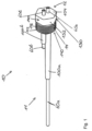
- Figure 1 shows a three-dimensional representation of a first exemplary embodiment of a disposable connection device 10 with a first sensor 60a designed as a level gauge and a second sensor 60b designed as a level gauge.
- the disposable connection device 10 comprises an outer end 12 on which a limiting disk 104 is arranged.
- the limiting disk 104 covers an end face of a force-absorbing section 130 designed as a sleeve, wherein the end face covered by the limiting disk 104 faces the outer end 12.
- the force-absorbing section 130 designed as a sleeve has an outer peripheral surface.
- This outer peripheral surface of the force-absorbing section 130 has a polygonal profile 140, which is designed here as a hexagonal profile.
- the polygonal profile 140 consists of six flat, equally sized surfaces 142 that are evenly distributed on the outer peripheral surface of the force-absorbing section 130.
- the individual surfaces 142 are arranged such that their respective surface normals run through the central axis of a sleeve 14 and two edges of an individual surface in turn border on one edge of two further surfaces.
- a fastening section 110 is arranged on the force-absorbing section 130, which has the same central axis as the force-absorbing section 130.
- the fastening section 110 is also designed as a sleeve with a constant diameter, wherein the diameter of the fastening section 110 is smaller than the diameter of the force-absorbing section 130. This creates a step or a shoulder at the transition from the force-absorbing section 130 to the fastening section 110. This shoulder serves as a stop surface 120, so that the disposable connection device 10 can be inserted into a connection opening up to this transition. of a bioreactor.
- the fastening section 110 has an outer peripheral surface 112 on which an external thread 116 is attached.
- a first inner tube section 100a and a second inner tube section 100b emerge from the sleeve which forms the fastening section 110, each with a passage direction in the direction of the inner end 11.
- the projection length, based on the exit from the fastening section 110, of the two inner tube sections 100a, 100b is different, with the first inner tube section 100a having approximately three times the projection length as the second inner tube section 100b.
- Figure 1 a first level meter 60a and a second level meter 60b, which are designed here as rod electrodes.
- the two level meters 60a, 60b essentially have the task of measuring the vertical height of a medium in the bioreactor and passing this value on to another device in a suitable form.
- One level meter is essentially designed to detect the upper level and the other level meter is essentially designed to detect the lower level.
- the two level gauges 60a, 60b can also be used to measure foam formation.
- the electrical conductivity between the two electrodes is preferably measured, whereby foam is characterized by a lower electrical conductivity compared to the medium and thus foam formation in the bioreactor can be detected.
- the fill level gauge 60a is arranged with part of its longitudinal extension in the passage of the first inner pipe section 100a.
- the fill level gauge 60a can either be introduced into the passage or already overmolded in the production process of the disposable connection device 10.
- the arrangement and introduction of the first fill level gauge 60a applies analogously to the arrangement and introduction of the second fill level gauge 60b into the passage of the second inner pipe section 100b.
- the passages of the inner pipe segments 100a, 100b extend to the outer end 12, so that the limiting disk 104 has two through openings.
- the fill level gauges 60a, 60b preferably each protrude from the disposable connection device 10 with one end, so that, for example, it is possible to connect the fill level gauges 60a, 60b to other devices.
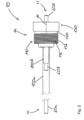
- Figure 2 shows a side view of the disposable connection device according to Figure 1 with a first level gauge 60a and a second level gauge 60b.
- a first level gauge 60a and a second level gauge 60b emerges from the disposable connection device 10.
- the end of the first level gauge 60a at the outer end 12 is in the Figure 2 covered by the end of the second level gauge 60b, so that the former is not shown.
- the ends of the level gauges 60a, 60b therefore protrude at the outer end 12 from a sleeve 14 which comprises a force-absorbing section 130, a stop surface 120 and a fastening section 110.
- the sleeve has a central axis M, which is also the central axis of the force-absorbing section 130 and the fastening section 110.
- the force-absorbing section 130 is designed as a sleeve, with the fastening section 110 being arranged on the force-absorbing section 130 in the direction of the inner end 11.
- the fastening section is also designed as a sleeve, with the diameter of the fastening section 110 being smaller than the diameter of the force-absorbing section 130. This difference in diameter creates a step at the transition from the fastening section 110 to the force-absorbing section 130, which forms a surface whose surface normal is aligned orthogonally to the central axis M. This surface serves as a stop surface 120, so that the disposable connection device 10 is inserted into the connection opening up to this stop surface 120 when inserted into a connection opening of a bioreactor.
- the force-absorbing section 130 preferably remains completely outside the connection opening.
- the fastening section 110 has an outer circumferential surface 112 on which an integrally designed fastening structure 114 is arranged.
- the fastening structure 114 is designed as an external thread 116 which has a number of turns.
- the two inner tube segments 100a, 100b are arranged parallel to the central axis M. Furthermore, the two inner tube segments 100a, 100b emerge from the sleeve on the side of the inner end and each have different projection lengths. At the end of the two inner tube segments 100a, 100b directed towards the outer end 12 of the disposable connection device, one of the level gauges 60a, 60b emerges.
- FIG 3a shows a longitudinal sectional view of a disposable connection device according to Figure 1 .
- the disposable connection device 10 extends from an outer end 12 to an inner end 11.
- a first level gauge 60a and a second level gauge 60b emerge from the disposable connection device 10 in the longitudinal direction.
- the level gauges 60a, 60b are designed as rod electrodes, analogous to the previous descriptions of the figures.
- the outer end 12 of the disposable connection device 10 is formed by a force-absorbing section 130, which is designed to absorb an externally applied force with which, for example, the disposable connection device 10 can be introduced into a connection device.
- a fastening section 110 is arranged on the force-absorbing section 130.
- the fastening section 110 is formed by an outer circumferential surface 112, which has a smaller diameter than the force-absorbing section 130. This difference in diameter creates a step at the transition from the force-absorbing section 130 to the fastening section 110.
- a surface created as a result has a surface normal that is aligned parallel to a central axis of the force-absorbing section 130 and the fastening section 110.
- the stop surface 120 created in this way is used to insert the disposable connection device 10 into a connection opening of a bioreactor.
- the stop surface 120 rests on a surface that is located in the immediate vicinity of the connection opening.
- the fastening section 110 has a fastening structure 114 on the outer circumferential surface 112, which in the present embodiment is designed as an external thread 116.
- Two inner tube segments 100a are arranged on the front side of the fastening section 110, which faces the inner end 11.
- the center axes of these two inner tube segments 100a are parallel to the center axis of the force-absorbing section 130 and the fastening section 110.
- the designated fill level gauges 60a, 60b emerge at the ends of the first inner tube segment 100a and the second inner tube segment 100b directed towards the outer end 12 of the disposable connection device.
- the level gauges 60a, 60b therefore extend completely from the outer end 12 to the inner end 11 of the disposable connection device 10.
- the level gauges 60a, 60b are each inserted into passages or are already overmolded during the production process, wherein the passages each lead with a common central axis through the pipe segments 100a, the fastening section 110 and the force absorption section 130.
- Figure 3b shows a longitudinal sectional view of a possible variant of the disposable connection device 10 according to Figure 1 , whereby the disposable connection device 10 here, in contrast to the variant in Figure 3a , a cavity in the region of a force-absorbing section 130 and in the region of the fastening section 110.
- the cavity is surrounded in the radial direction by a central axis M, the outer surface of this wall comprising an external thread 116 in the region of the fastening section 110.
- the limiting disk 104 separates the interior of a bioreactor from the surroundings of the bioreactor.
- a first outer pipe segment 101a and a second outer pipe segment 101b are arranged on the side of the limiting disk 104 facing the outer end 12.
- the first outer pipe segment 101a has the same passage as the first inner pipe segment 100a.
- the second outer pipe segment 101b has the same passage as the second inner pipe segment 100b.
- the limiting disk 104 has through holes, the passage direction and the center axis of which each correspond to the passage direction and the center axis of the pipe segments arranged on them.
- FIG 4 shows a three-dimensional representation of a second exemplary embodiment of a disposable connection device 20.
- the disposable connection device 20 has an inner end 21 and an outer end 22.
- the inner end 21 of the disposable connection device 20 is the end that is introduced and/or inserted into a connection opening of a bioreactor.
- the inner end 21 is therefore facing the interior of the bioreactor when inserted.
- the inner end 21 comprises a first inner tube segment 200a, a second inner tube segment 200b and a third inner tube segment 200c.
- the inner tube segments 200a, 200b, 200c each have the same axial length and also the same projection length in relation to a limiting disk 204.
- the limiting disk 204 has a flat geometry whose surface normal runs parallel to the direction of passage of the tube segments.
- the inner tube segments 200a, 200b, 200c each have a passage 202a, 202b, 202c.
- the three inner tube segments 200a, 200b, 200c are further spaced apart from one another in the
- the outer end 22 is the end that is not inserted and/or inserted into the connection opening of the bioreactor. The outer end 22 is therefore facing away from the interior of the bioreactor when inserted.
- the outer end 22 comprises three outer tube segments 201a, 201b, 201c, which each have the same axial length and are spaced apart from one another in the radial direction.
- the three outer tube segments Furthermore, in this embodiment variant, they have the same projection length relative to the limiting disk 204.
- the outer tube segments 201a, 201b, 201c also each comprise the passages 202a, 202b, 202c.
- Each individual passage 202a, 202b, 202c runs completely through the one-way connection device, so that a passage 202a, 202b, 202c begins at the inner end 21 in an inner tube segment 200a, 200b, 200c and preferably runs uninterrupted to the outer end 22 in an outer tube segment 201a, 201b, 201c.
- the passage 202a is therefore predominantly formed by the first inner tube segment 200a and the first outer tube segment 201a.
- the passage 202b is further predominantly formed by the second inner tube segment 200b and the second outer tube segment 201b.
- the passage 202c is further predominantly formed by the third inner tube segment 200c and the third outer tube segment 201c.
- a single inner pipe segment 200a, 200b, 200c and a corresponding single outer pipe segment 201a, 201b, 201c therefore have a common central axis.
- An inner pipe segment 200a, 200b, 200c and a corresponding outer pipe segment 201a, 201b, 201c with a common central axis are held in a defined position by the circular limiting disk 204 arranged orthogonally to the central axis.
- the circular disk 204 has passage openings so that the passages 202a, 202b, 202c are continuous from the inner end 21 to the outer end 22.
- the ends of the inner tube segments 200a, 200b, 200c each have an end face that is inclined at approximately 45 degrees to the center axis of the tube segment.
- the wall thickness of the outer tube segments 201a, 201b, 201c decreases towards the outer end, with the wall thickness being approximately halved.
- the inner and outer tube segments and the limiting disk 204 are surrounded in the radial direction by a sleeve 24, which has a fastening section 210, a stop surface 220 and a force-absorbing section 230.
- the fastening section 210 has an outer circumferential surface 212.
- the outer circumferential surface 212 also has a substantially constant diameter.
- a fastening structure 214 is realized here in the form of an outer diameter of the fastening section 210 that is dimensioned such that a clamp connection or a press fit of the disposable connection device 20 is realized in a connection opening.
- the force-absorbing section 230 is arranged directly at the end of the fastening section 210 that faces the outer end 22.
- the force-absorbing section 230 has a circular inner diameter that is larger than the inner diameter of the fastening section 210.
- the outer peripheral surface of the force-absorbing section 230 has a twelve-sided profile 240.
- the twelve-sided profile 240 consists of twelve flat, equally sized surfaces 242 that are evenly distributed on the outer peripheral surface of the force-absorbing section 230.
- the individual surfaces 142 are arranged in such a way that their respective surface normals run through the center axis of the sleeve 24 and two opposite edges of an individual surface in turn border on an edge of two further surfaces.
- a connection opening of a bioreactor is preferably designed such that the diameter of the connection opening has the same or a smaller dimension than the diameter of the fastening section 210. Furthermore, the diameter of the connection opening is smaller than the diameter of the force-absorbing section 230, so that the aforementioned step acts as a stop surface 220. After the disposable connection device 20 has been inserted, the stop surface 220 rests on the surface of the element of the bioreactor that has the connection opening.
- FIG 5 shows a longitudinal sectional view of a variant of the disposable connection device according to Figure 4 .
- the disposable connection device 20 has a total of three outer tube segments at the outer end 22, wherein the tube segment 201b is arranged outside the cutting plane and the tube segment 201c is shown in an uncut perspective, since it lies behind the cutting plane.
- the disposable connection device 20 also has a sleeve 24 which comprises the force-absorbing section 230, the stop surface 220 and the fastening section 210.
- the fastening section 210 has a rotationally symmetrical shape with respect to the central axis M, so that the fastening section 210 also has the shape of a sleeve.
- the fastening section 210 also comprises an outer peripheral surface 212 to which a fastening structure (not shown) can be attached.
- the limiting disk 204 therefore has a surface normal that is aligned parallel to the central axis M.
- the outer pipe segments 201a, 201b, 201c and the inner pipe segments 200a, 200b, 200c are also arranged on the limiting disk 204.
- an outer pipe segment and an inner pipe segment each form a common passage 202a, 202b or 202c.
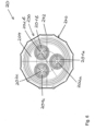
- Figure 6 shows a plan view of the disposable connection device 20 according to Figure 4 .
- Three outer pipe segments 201a, 201b, 201c are arranged on the limiting disk 204.
- the outer pipe segments 201a, 201b, 201c also have a circular cross-section, with their centers each having the same distance from the center of the limiting disk 204.
- the three outer pipe segments have the previously designated passages 202a, 202b or 202c.
- the disposable connection device 20 also comprises a force-absorbing section 230, which is designed to be subjected to a radial and/or axial force in order to attach the disposable connection device 20 preferably in and/or to a connection opening of a bioreactor.
- the force-absorbing section 230 therefore has the previously described polygonal profile, which here essentially consists of twelve polygonal profile surfaces 242.
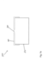
- FIG. 7a shows a schematic representation of a bioreactor 50 with a head plate 40.
- the bioreactor 50 comprises a bioreactor container 51, which is preferably completely enclosed with the exception of one side.
- the container is preferably made of a metallic material, preferably stainless steel, and/or plastic, or comprises these materials.
- the unenclosed side of the bioreactor container 51 is closed by a head plate 40.
- the head plate also has a connection opening 30, which is designed to accommodate a disposable connection device 10, 20 according to the invention.
- the connection opening 30 preferably has an internal thread on its inner peripheral surface, which enables the accommodation of a complementary external thread on a disposable connection device 10, 20.
- Figure 7b shows a schematic representation of a bag bioreactor 55 with a connection element 45 and a bag 56 that is essentially or at least partially non-dimensionally stable.
- the connection element 45 is arranged on the bag 56 in such a way that the separating line between the connection element 45 and the bag 56 can ensure a preferably hermetic seal of the interior of the bag 56 from the surroundings of the bag bioreactor 55.
- the connection element 45 also has a connection opening 30, which in the present embodiment has a circular cross-section.
- the connection opening 30 is designed to accommodate a disposable connection device 10, 20 according to the invention.
- the connection opening 30 preferably has an internal thread on its inner peripheral surface, which enables the reception of a complementary external thread on a disposable connection device 10, 20.
Landscapes
- Health & Medical Sciences (AREA)
- Life Sciences & Earth Sciences (AREA)
- Chemical & Material Sciences (AREA)
- Wood Science & Technology (AREA)
- Organic Chemistry (AREA)
- Engineering & Computer Science (AREA)
- Bioinformatics & Cheminformatics (AREA)
- Zoology (AREA)
- Biomedical Technology (AREA)
- Sustainable Development (AREA)
- Microbiology (AREA)
- Biotechnology (AREA)
- Biochemistry (AREA)
- General Engineering & Computer Science (AREA)
- General Health & Medical Sciences (AREA)
- Genetics & Genomics (AREA)
- Clinical Laboratory Science (AREA)
- Molecular Biology (AREA)
- Analytical Chemistry (AREA)
- Apparatus Associated With Microorganisms And Enzymes (AREA)
Priority Applications (8)
| Application Number | Priority Date | Filing Date | Title |
|---|---|---|---|
| DK16153294.0T DK3199616T3 (da) | 2016-01-29 | 2016-01-29 | Engangsforbindelsesindretning |
| EP16153294.0A EP3199616B1 (de) | 2016-01-29 | 2016-01-29 | Einweg-anschlusseinrichtung |
| JP2018539400A JP6959929B2 (ja) | 2016-01-29 | 2017-01-27 | 使い捨て連結装置 |
| EP17701548.4A EP3408370B1 (de) | 2016-01-29 | 2017-01-27 | Einweg-anschlusseinrichtung |
| DK17701548.4T DK3408370T3 (da) | 2016-01-29 | 2017-01-27 | Envejs-tilslutningsindretning |
| CN201780009051.2A CN108603156B (zh) | 2016-01-29 | 2017-01-27 | 一次性连接装置 |
| US16/072,630 US11608484B2 (en) | 2016-01-29 | 2017-01-27 | Single-use connection device |
| PCT/EP2017/051865 WO2017129800A1 (de) | 2016-01-29 | 2017-01-27 | Einweg-anschlusseinrichtung |
Applications Claiming Priority (1)
| Application Number | Priority Date | Filing Date | Title |
|---|---|---|---|
| EP16153294.0A EP3199616B1 (de) | 2016-01-29 | 2016-01-29 | Einweg-anschlusseinrichtung |
Publications (2)
| Publication Number | Publication Date |
|---|---|
| EP3199616A1 EP3199616A1 (de) | 2017-08-02 |
| EP3199616B1 true EP3199616B1 (de) | 2024-08-21 |
Family
ID=55272305
Family Applications (2)
| Application Number | Title | Priority Date | Filing Date |
|---|---|---|---|
| EP16153294.0A Active EP3199616B1 (de) | 2016-01-29 | 2016-01-29 | Einweg-anschlusseinrichtung |
| EP17701548.4A Active EP3408370B1 (de) | 2016-01-29 | 2017-01-27 | Einweg-anschlusseinrichtung |
Family Applications After (1)
| Application Number | Title | Priority Date | Filing Date |
|---|---|---|---|
| EP17701548.4A Active EP3408370B1 (de) | 2016-01-29 | 2017-01-27 | Einweg-anschlusseinrichtung |
Country Status (6)
| Country | Link |
|---|---|
| US (1) | US11608484B2 (da) |
| EP (2) | EP3199616B1 (da) |
| JP (1) | JP6959929B2 (da) |
| CN (1) | CN108603156B (da) |
| DK (2) | DK3199616T3 (da) |
| WO (1) | WO2017129800A1 (da) |
Families Citing this family (6)
| Publication number | Priority date | Publication date | Assignee | Title |
|---|---|---|---|---|
| DK3199616T3 (da) | 2016-01-29 | 2024-11-25 | Eppendorf Se | Engangsforbindelsesindretning |
| EP3514223A1 (de) * | 2018-01-17 | 2019-07-24 | Eppendorf AG | Multisensor für einen bioreaktor, bioreaktor, verfahren zur herstellung eines multisensors und zur messung von parametern |
| DE102018210370A1 (de) | 2018-06-26 | 2020-01-02 | Irubis Gmbh | Einweg-Bioreaktor und dessen Verwendung |
| DE102019110742B4 (de) | 2019-04-25 | 2021-06-10 | Sartorius Stedim Biotech Gmbh | Vorrichtung zur mechanischen Stabilisierung eines Anschlusses, insbesondere eines Sensoranschlusses, an einem flexiblen Beutel |
| US20210016287A1 (en) | 2019-07-16 | 2021-01-21 | Ge Healthcare Bio-Sciences Corp. | Reinforced bioreactor component structure system for cell cultivation |
| EP4053260A1 (en) * | 2021-03-04 | 2022-09-07 | Bühler AG | Device with an insert for treating cell material |
Citations (2)
| Publication number | Priority date | Publication date | Assignee | Title |
|---|---|---|---|---|
| EP2674479A1 (de) * | 2012-06-15 | 2013-12-18 | Eppendorf Ag | Einwegbioreaktor und Kopfplatte sowie Herstellungsverfahren |
| WO2015135376A1 (zh) * | 2014-03-08 | 2015-09-17 | 郑州威瑞生物技术有限公司 | 一次性生物反应器 |
Family Cites Families (45)
| Publication number | Priority date | Publication date | Assignee | Title |
|---|---|---|---|---|
| DE2137854C3 (de) * | 1971-07-29 | 1975-09-18 | Draegerwerk Ag, 2400 Luebeck | Prüfröhrchen |
| US4639422A (en) * | 1986-02-03 | 1987-01-27 | Monsanto Company | Cell culture filter apparatus and method |
| US5368801A (en) | 1993-01-05 | 1994-11-29 | Vlv Associates | Method of mounting a septum in a connector |
| US5350080A (en) | 1993-02-10 | 1994-09-27 | Hyclone Laboratories | Multi-access port for use in a cell culture media system |
| DE19709603C2 (de) | 1997-03-08 | 1999-03-18 | Forschungszentrum Juelich Gmbh | Verfahren und Vorrichtung zur Serienkultivierung von Organismen |
| DE19729492A1 (de) | 1997-07-10 | 1999-02-11 | Forschungszentrum Juelich Gmbh | Verfahren und Vorrichtung zur Serienprobenahme |
| US6604908B1 (en) | 1999-07-20 | 2003-08-12 | Deka Products Limited Partnership | Methods and systems for pulsed delivery of fluids from a pump |
| DE10016554A1 (de) * | 2000-04-03 | 2001-10-18 | Rootec Ges Fuer Bioaktive Wirk | Vorrichtung zum Kultivieren von pflanzlichen oder tierischen Gewebekulturen |
| DE10024992C2 (de) | 2000-05-22 | 2002-09-19 | Forschungszentrum Juelich Gmbh | Verfahren und Vorrichtung für die Bestimmung von Substrat- und Produktkonzentrationen in einem Medium |
| DE10024969A1 (de) | 2000-05-22 | 2001-12-06 | Forschungszentrum Juelich Gmbh | Verfahren für die Bestimmung von Substrat- und Produktkonzentrationen in einem Medium |
| US6908459B2 (en) | 2001-12-07 | 2005-06-21 | Becton, Dickinson And Company | Needleless luer access connector |
| TWM249914U (en) * | 2003-12-17 | 2004-11-11 | Exon Science Inc | Fast opening/closing gate for biochemical facility |
| WO2006044441A2 (en) | 2004-10-19 | 2006-04-27 | Agilent Technologies, Inc. | Fluid processing devices with multiple sealing mechanisms and automated methods of use thereof |
| JP4986659B2 (ja) * | 2006-03-23 | 2012-07-25 | 藤森工業株式会社 | 培養袋及び培養器 |
| JP4802875B2 (ja) * | 2006-06-12 | 2011-10-26 | ニプロ株式会社 | 細胞培養容器及び細胞移注方法 |
| US8008065B2 (en) * | 2006-08-02 | 2011-08-30 | Finesse Solutions, Llc. | Disposable bioreactor vessel port |
| US8057092B2 (en) * | 2006-11-30 | 2011-11-15 | Corning Incorporated | Disposable spinner flask |
| US20090120169A1 (en) * | 2007-11-12 | 2009-05-14 | Chandler Jr William H | Fluid sensor and methods of making components thereof |
| DE102007059533A1 (de) * | 2007-12-06 | 2009-06-10 | Thinxxs Microtechnology Ag | Mikrofluidische Speichervorrichtung |
| DE102008060773A1 (de) | 2008-12-05 | 2010-06-10 | Sartorius Stedim Biotech Gmbh | Verschluss für einen Behälter |
| WO2010069320A2 (en) | 2008-12-19 | 2010-06-24 | Stobbe Tech A/S | Biopharmaceutical plant in a column |
| JP5383272B2 (ja) * | 2009-03-26 | 2014-01-08 | 富士フイルム株式会社 | 細胞培養用メンブレン |
| EP2251407B1 (en) * | 2009-05-12 | 2016-06-29 | Eppendorf AG | Disposable bioreactor and method for its production |
| AU2010286628B8 (en) * | 2009-08-26 | 2015-11-19 | Global Life Sciences Solutions Usa Llc | Continuous recovery harvest bag |
| CN101693878B (zh) * | 2009-10-21 | 2012-06-13 | 青岛生物能源与过程研究所 | 一种微藻浓缩和收集的方法与装置 |
| US20130026167A1 (en) * | 2010-03-30 | 2013-01-31 | Advanced Technology Materials, Inc. | Container sealing system |
| WO2011144561A1 (en) * | 2010-05-18 | 2011-11-24 | Crucell Holland B.V. | Methods for welding ethylene vinyl acetate (eva) tubing, tubing obtained thereby and use of such tubing for sterile transfer of content into a bioreactor |
| US9550969B2 (en) * | 2011-03-18 | 2017-01-24 | Ge Healthcare Bio-Sciences Ab | Flexible bag for cultivation of cells |
| CN103975055B (zh) * | 2011-10-10 | 2016-05-04 | 德国达斯其普信息与程序技术有限公司 | 包括生物反应器的生物技术装置、用于生物反应器的排出气体温度控制装置以及用于处理生物技术装置中的排出气流的方法 |
| WO2013053778A1 (en) | 2011-10-10 | 2013-04-18 | DASGIP Information and Process Technology GmbH | Method for controlled operation of a biotechnological apparatus and bioreactor systems |
| DE102012102918A1 (de) | 2012-04-03 | 2013-10-10 | Eppendorf Ag | Laborgerätesystem und Laborgerät zum Behandeln von Fluiden und Feststoffen sowie Verfahren zum Betreiben eines Laborgerätes |
| WO2013158756A1 (en) | 2012-04-17 | 2013-10-24 | Dr. Py Institute, Llc | Self closing connector |
| GB201213506D0 (en) * | 2012-07-30 | 2012-09-12 | Tap Biosystems Phc Ltd | Bioreactor vessels and associated bioreactor systems |
| US9481477B2 (en) | 2012-09-17 | 2016-11-01 | Life Technologies Corporation | Fluid manifold system with rotatable port assembly |
| CA2884865A1 (en) * | 2012-09-18 | 2014-03-27 | Bayer Technology Services Gmbh | Disposable bottle reactor tank |
| DE202013004096U1 (de) | 2013-05-03 | 2013-06-06 | Sartorius Stedim Biotech Gmbh | System zur Abluftumschaltung eines Bioreaktors |
| EP2853584B1 (en) * | 2013-09-30 | 2021-03-10 | Eppendorf Ag | Single-use bioreactor with baffles and a process for manufacturing and operating the same |
| EP3071683A1 (en) * | 2013-11-21 | 2016-09-28 | Distek, Inc. | Disposable bioreactors and methods for construction and use thereof |
| US9677975B2 (en) | 2014-10-31 | 2017-06-13 | General Electric Company | Systems and methods for aseptic sampling |
| DK3199616T3 (da) | 2016-01-29 | 2024-11-25 | Eppendorf Se | Engangsforbindelsesindretning |
| DE102016015207A1 (de) | 2016-12-21 | 2018-06-21 | Fresenius Medical Care Deutschland Gmbh | Betätigungseinrichtung und Verfahren zum Betreiben einer Betätigungseinrichtung sowie Membranpumpe mit einer Betätigungseinrichtung und einer Membranpumpeneinrichtung und eine Blutbehandlungsvorrichtung mit einer Membranpumpe |
| WO2018115028A1 (de) | 2016-12-21 | 2018-06-28 | Fresenius Medical Care Deutschland Gmbh | Membranpumpeneinrichtung und membranpumpe mit einer membranpumpeneinrichtung und einer betätigungseinrichtung |
| EP3460036B1 (en) | 2017-09-22 | 2020-02-12 | Sartorius Stedim Biotech GmbH | Sterile probe sampling for a single-use vessel |
| EP3514223A1 (de) | 2018-01-17 | 2019-07-24 | Eppendorf AG | Multisensor für einen bioreaktor, bioreaktor, verfahren zur herstellung eines multisensors und zur messung von parametern |
| JP2022539428A (ja) | 2019-07-12 | 2022-09-08 | エッペンドルフ・ソシエタス・エウロパエア | センサ無し膜ポンプの制御配置及び制御方法 |
-
2016
- 2016-01-29 DK DK16153294.0T patent/DK3199616T3/da active
- 2016-01-29 EP EP16153294.0A patent/EP3199616B1/de active Active
-
2017
- 2017-01-27 DK DK17701548.4T patent/DK3408370T3/da active
- 2017-01-27 US US16/072,630 patent/US11608484B2/en active Active
- 2017-01-27 JP JP2018539400A patent/JP6959929B2/ja active Active
- 2017-01-27 WO PCT/EP2017/051865 patent/WO2017129800A1/de not_active Ceased
- 2017-01-27 CN CN201780009051.2A patent/CN108603156B/zh active Active
- 2017-01-27 EP EP17701548.4A patent/EP3408370B1/de active Active
Patent Citations (2)
| Publication number | Priority date | Publication date | Assignee | Title |
|---|---|---|---|---|
| EP2674479A1 (de) * | 2012-06-15 | 2013-12-18 | Eppendorf Ag | Einwegbioreaktor und Kopfplatte sowie Herstellungsverfahren |
| WO2015135376A1 (zh) * | 2014-03-08 | 2015-09-17 | 郑州威瑞生物技术有限公司 | 一次性生物反应器 |
Also Published As
| Publication number | Publication date |
|---|---|
| JP2019503194A (ja) | 2019-02-07 |
| EP3408370B1 (de) | 2021-04-07 |
| CN108603156A (zh) | 2018-09-28 |
| DK3199616T3 (da) | 2024-11-25 |
| US20190031995A1 (en) | 2019-01-31 |
| EP3199616A1 (de) | 2017-08-02 |
| EP3408370A1 (de) | 2018-12-05 |
| JP6959929B2 (ja) | 2021-11-05 |
| DK3408370T3 (da) | 2021-07-05 |
| CN108603156B (zh) | 2022-05-10 |
| WO2017129800A1 (de) | 2017-08-03 |
| US11608484B2 (en) | 2023-03-21 |
Similar Documents
| Publication | Publication Date | Title |
|---|---|---|
| EP3199616B1 (de) | Einweg-anschlusseinrichtung | |
| EP2674479B1 (de) | Einwegbioreaktor und Kopfplatte sowie Herstellungsverfahren | |
| EP2443420B1 (de) | Behälter mit einem sensoradapter | |
| EP3120929B1 (de) | Einlassventil für kammersysteme und probenbhälter sowie kammersysteme und probenbehälter mit derartigen einlassventilen | |
| DE202016000554U1 (de) | Einweg-Anschlusseinrichtung | |
| EP2373550B1 (de) | Verschluss für einen behälter | |
| EP1261690B1 (de) | Vorrichtung zum züchten von keimkulturen | |
| DE102019115147B4 (de) | Biokompatibles Verbundelement und Verfahren zur Herstellung eines biokompatiblen Verbundelements | |
| DE102011000061B4 (de) | Perfusionsbioreaktor zum Kultivieren von Zellen auf Gerüstmaterialien | |
| EP2674480B2 (de) | Anschlussvorrichtung für eine sterile Einweg-Fluidleitung eines Einwegbioreaktors und Verfahren zum Behandeln eines Fluidstroms | |
| EP3618962B1 (de) | Abnahmebaugruppe oder teströhrchen für eine geringe menge einer körperflüssigkeit mit einem verlängerungselement | |
| DE3905158C2 (da) | ||
| EP3942013B1 (de) | Behälter zur aufbewahrung, mischung und/oder kultivierung eines mediums | |
| DE10213066B4 (de) | Prüfvorrichtung für einen Sterilisationsvorgang | |
| DE102019117411A1 (de) | Probenbehälter und Verwendung eines Probenbehälters | |
| WO2024188745A1 (de) | Vorrichtung für spektroskopische messungen an bioreaktoren | |
| EP3740558A1 (de) | Multisensor für einen bioreaktor, bioreaktor, verfahren zur herstellung eines multisensors und zur messung von parametern | |
| EP4317398B1 (de) | Befestigungselement zur anordnung an ein anschlusselement eines prozessbehälters | |
| CH659083A5 (de) | Vorrichtung zur bestimmung von mikroorganismen. | |
| EP4196567A1 (de) | Vorrichtung zum sterilen flüssigkeitstransfer | |
| DE29518510U1 (de) | Vorrichtung zur sterilen Entnahme von Proben aus Behältern | |
| WO2025237604A1 (de) | Mehrteilige mikrotiterplatte | |
| DE102004046724B3 (de) | Reaktionsgefäß und Verfahren zur Behandlung biologischen Materials | |
| DE202004006024U1 (de) | Flusskammer im Well | |
| DE202005015260U1 (de) | Reaktionsgefäß |
Legal Events
| Date | Code | Title | Description |
|---|---|---|---|
| PUAI | Public reference made under article 153(3) epc to a published international application that has entered the european phase |
Free format text: ORIGINAL CODE: 0009012 |
|
| STAA | Information on the status of an ep patent application or granted ep patent |
Free format text: STATUS: THE APPLICATION HAS BEEN PUBLISHED |
|
| AK | Designated contracting states |
Kind code of ref document: A1 Designated state(s): AL AT BE BG CH CY CZ DE DK EE ES FI FR GB GR HR HU IE IS IT LI LT LU LV MC MK MT NL NO PL PT RO RS SE SI SK SM TR |
|
| AX | Request for extension of the european patent |
Extension state: BA ME |
|
| STAA | Information on the status of an ep patent application or granted ep patent |
Free format text: STATUS: REQUEST FOR EXAMINATION WAS MADE |
|
| 17P | Request for examination filed |
Effective date: 20180202 |
|
| RBV | Designated contracting states (corrected) |
Designated state(s): AL AT BE BG CH CY CZ DE DK EE ES FI FR GB GR HR HU IE IS IT LI LT LU LV MC MK MT NL NO PL PT RO RS SE SI SK SM TR |
|
| STAA | Information on the status of an ep patent application or granted ep patent |
Free format text: STATUS: EXAMINATION IS IN PROGRESS |
|
| 17Q | First examination report despatched |
Effective date: 20200221 |
|
| RAP3 | Party data changed (applicant data changed or rights of an application transferred) |
Owner name: EPPENDORF SE |
|
| GRAP | Despatch of communication of intention to grant a patent |
Free format text: ORIGINAL CODE: EPIDOSNIGR1 |
|
| STAA | Information on the status of an ep patent application or granted ep patent |
Free format text: STATUS: GRANT OF PATENT IS INTENDED |
|
| INTG | Intention to grant announced |
Effective date: 20230918 |
|
| GRAJ | Information related to disapproval of communication of intention to grant by the applicant or resumption of examination proceedings by the epo deleted |
Free format text: ORIGINAL CODE: EPIDOSDIGR1 |
|
| STAA | Information on the status of an ep patent application or granted ep patent |
Free format text: STATUS: EXAMINATION IS IN PROGRESS |
|
| INTC | Intention to grant announced (deleted) | ||
| GRAP | Despatch of communication of intention to grant a patent |
Free format text: ORIGINAL CODE: EPIDOSNIGR1 |
|
| STAA | Information on the status of an ep patent application or granted ep patent |
Free format text: STATUS: GRANT OF PATENT IS INTENDED |
|
| INTG | Intention to grant announced |
Effective date: 20240318 |
|
| GRAS | Grant fee paid |
Free format text: ORIGINAL CODE: EPIDOSNIGR3 |
|
| GRAA | (expected) grant |
Free format text: ORIGINAL CODE: 0009210 |
|
| STAA | Information on the status of an ep patent application or granted ep patent |
Free format text: STATUS: THE PATENT HAS BEEN GRANTED |
|
| AK | Designated contracting states |
Kind code of ref document: B1 Designated state(s): AL AT BE BG CH CY CZ DE DK EE ES FI FR GB GR HR HU IE IS IT LI LT LU LV MC MK MT NL NO PL PT RO RS SE SI SK SM TR |
|
| REG | Reference to a national code |
Ref country code: GB Ref legal event code: FG4D Free format text: NOT ENGLISH |
|
| REG | Reference to a national code |
Ref country code: CH Ref legal event code: EP |
|
| REG | Reference to a national code |
Ref country code: DE Ref legal event code: R096 Ref document number: 502016016670 Country of ref document: DE |
|
| REG | Reference to a national code |
Ref country code: IE Ref legal event code: FG4D Free format text: LANGUAGE OF EP DOCUMENT: GERMAN |
|
| REG | Reference to a national code |
Ref country code: DE Ref legal event code: R082 Ref document number: 502016016670 Country of ref document: DE |
|
| REG | Reference to a national code |
Ref country code: DK Ref legal event code: T3 Effective date: 20241120 |
|
| REG | Reference to a national code |
Ref country code: NL Ref legal event code: FP |
|
| REG | Reference to a national code |
Ref country code: LT Ref legal event code: MG9D |
|
| PG25 | Lapsed in a contracting state [announced via postgrant information from national office to epo] |
Ref country code: NO Free format text: LAPSE BECAUSE OF FAILURE TO SUBMIT A TRANSLATION OF THE DESCRIPTION OR TO PAY THE FEE WITHIN THE PRESCRIBED TIME-LIMIT Effective date: 20241121 |
|
| PG25 | Lapsed in a contracting state [announced via postgrant information from national office to epo] |
Ref country code: FI Free format text: LAPSE BECAUSE OF FAILURE TO SUBMIT A TRANSLATION OF THE DESCRIPTION OR TO PAY THE FEE WITHIN THE PRESCRIBED TIME-LIMIT Effective date: 20240821 Ref country code: GR Free format text: LAPSE BECAUSE OF FAILURE TO SUBMIT A TRANSLATION OF THE DESCRIPTION OR TO PAY THE FEE WITHIN THE PRESCRIBED TIME-LIMIT Effective date: 20241122 Ref country code: PT Free format text: LAPSE BECAUSE OF FAILURE TO SUBMIT A TRANSLATION OF THE DESCRIPTION OR TO PAY THE FEE WITHIN THE PRESCRIBED TIME-LIMIT Effective date: 20241223 Ref country code: PL Free format text: LAPSE BECAUSE OF FAILURE TO SUBMIT A TRANSLATION OF THE DESCRIPTION OR TO PAY THE FEE WITHIN THE PRESCRIBED TIME-LIMIT Effective date: 20240821 |
|
| PG25 | Lapsed in a contracting state [announced via postgrant information from national office to epo] |
Ref country code: BG Free format text: LAPSE BECAUSE OF FAILURE TO SUBMIT A TRANSLATION OF THE DESCRIPTION OR TO PAY THE FEE WITHIN THE PRESCRIBED TIME-LIMIT Effective date: 20240821 |
|
| PG25 | Lapsed in a contracting state [announced via postgrant information from national office to epo] |
Ref country code: LV Free format text: LAPSE BECAUSE OF FAILURE TO SUBMIT A TRANSLATION OF THE DESCRIPTION OR TO PAY THE FEE WITHIN THE PRESCRIBED TIME-LIMIT Effective date: 20240821 |
|
| PG25 | Lapsed in a contracting state [announced via postgrant information from national office to epo] |
Ref country code: IS Free format text: LAPSE BECAUSE OF FAILURE TO SUBMIT A TRANSLATION OF THE DESCRIPTION OR TO PAY THE FEE WITHIN THE PRESCRIBED TIME-LIMIT Effective date: 20241221 |
|
| PG25 | Lapsed in a contracting state [announced via postgrant information from national office to epo] |
Ref country code: HR Free format text: LAPSE BECAUSE OF FAILURE TO SUBMIT A TRANSLATION OF THE DESCRIPTION OR TO PAY THE FEE WITHIN THE PRESCRIBED TIME-LIMIT Effective date: 20240821 |
|
| PG25 | Lapsed in a contracting state [announced via postgrant information from national office to epo] |
Ref country code: RS Free format text: LAPSE BECAUSE OF FAILURE TO SUBMIT A TRANSLATION OF THE DESCRIPTION OR TO PAY THE FEE WITHIN THE PRESCRIBED TIME-LIMIT Effective date: 20241121 Ref country code: ES Free format text: LAPSE BECAUSE OF FAILURE TO SUBMIT A TRANSLATION OF THE DESCRIPTION OR TO PAY THE FEE WITHIN THE PRESCRIBED TIME-LIMIT Effective date: 20240821 |
|
| PG25 | Lapsed in a contracting state [announced via postgrant information from national office to epo] |
Ref country code: RS Free format text: LAPSE BECAUSE OF FAILURE TO SUBMIT A TRANSLATION OF THE DESCRIPTION OR TO PAY THE FEE WITHIN THE PRESCRIBED TIME-LIMIT Effective date: 20241121 Ref country code: PT Free format text: LAPSE BECAUSE OF FAILURE TO SUBMIT A TRANSLATION OF THE DESCRIPTION OR TO PAY THE FEE WITHIN THE PRESCRIBED TIME-LIMIT Effective date: 20241223 Ref country code: PL Free format text: LAPSE BECAUSE OF FAILURE TO SUBMIT A TRANSLATION OF THE DESCRIPTION OR TO PAY THE FEE WITHIN THE PRESCRIBED TIME-LIMIT Effective date: 20240821 Ref country code: NO Free format text: LAPSE BECAUSE OF FAILURE TO SUBMIT A TRANSLATION OF THE DESCRIPTION OR TO PAY THE FEE WITHIN THE PRESCRIBED TIME-LIMIT Effective date: 20241121 Ref country code: LV Free format text: LAPSE BECAUSE OF FAILURE TO SUBMIT A TRANSLATION OF THE DESCRIPTION OR TO PAY THE FEE WITHIN THE PRESCRIBED TIME-LIMIT Effective date: 20240821 Ref country code: IS Free format text: LAPSE BECAUSE OF FAILURE TO SUBMIT A TRANSLATION OF THE DESCRIPTION OR TO PAY THE FEE WITHIN THE PRESCRIBED TIME-LIMIT Effective date: 20241221 Ref country code: HR Free format text: LAPSE BECAUSE OF FAILURE TO SUBMIT A TRANSLATION OF THE DESCRIPTION OR TO PAY THE FEE WITHIN THE PRESCRIBED TIME-LIMIT Effective date: 20240821 Ref country code: GR Free format text: LAPSE BECAUSE OF FAILURE TO SUBMIT A TRANSLATION OF THE DESCRIPTION OR TO PAY THE FEE WITHIN THE PRESCRIBED TIME-LIMIT Effective date: 20241122 Ref country code: FI Free format text: LAPSE BECAUSE OF FAILURE TO SUBMIT A TRANSLATION OF THE DESCRIPTION OR TO PAY THE FEE WITHIN THE PRESCRIBED TIME-LIMIT Effective date: 20240821 Ref country code: ES Free format text: LAPSE BECAUSE OF FAILURE TO SUBMIT A TRANSLATION OF THE DESCRIPTION OR TO PAY THE FEE WITHIN THE PRESCRIBED TIME-LIMIT Effective date: 20240821 Ref country code: BG Free format text: LAPSE BECAUSE OF FAILURE TO SUBMIT A TRANSLATION OF THE DESCRIPTION OR TO PAY THE FEE WITHIN THE PRESCRIBED TIME-LIMIT Effective date: 20240821 |
|
| PG25 | Lapsed in a contracting state [announced via postgrant information from national office to epo] |
Ref country code: SM Free format text: LAPSE BECAUSE OF FAILURE TO SUBMIT A TRANSLATION OF THE DESCRIPTION OR TO PAY THE FEE WITHIN THE PRESCRIBED TIME-LIMIT Effective date: 20240821 Ref country code: RO Free format text: LAPSE BECAUSE OF FAILURE TO SUBMIT A TRANSLATION OF THE DESCRIPTION OR TO PAY THE FEE WITHIN THE PRESCRIBED TIME-LIMIT Effective date: 20240821 |
|
| PG25 | Lapsed in a contracting state [announced via postgrant information from national office to epo] |
Ref country code: EE Free format text: LAPSE BECAUSE OF FAILURE TO SUBMIT A TRANSLATION OF THE DESCRIPTION OR TO PAY THE FEE WITHIN THE PRESCRIBED TIME-LIMIT Effective date: 20240821 |
|
| PG25 | Lapsed in a contracting state [announced via postgrant information from national office to epo] |
Ref country code: CZ Free format text: LAPSE BECAUSE OF FAILURE TO SUBMIT A TRANSLATION OF THE DESCRIPTION OR TO PAY THE FEE WITHIN THE PRESCRIBED TIME-LIMIT Effective date: 20240821 |
|
| PG25 | Lapsed in a contracting state [announced via postgrant information from national office to epo] |
Ref country code: IT Free format text: LAPSE BECAUSE OF FAILURE TO SUBMIT A TRANSLATION OF THE DESCRIPTION OR TO PAY THE FEE WITHIN THE PRESCRIBED TIME-LIMIT Effective date: 20240821 Ref country code: SK Free format text: LAPSE BECAUSE OF FAILURE TO SUBMIT A TRANSLATION OF THE DESCRIPTION OR TO PAY THE FEE WITHIN THE PRESCRIBED TIME-LIMIT Effective date: 20240821 |
|
| REG | Reference to a national code |
Ref country code: DE Ref legal event code: R097 Ref document number: 502016016670 Country of ref document: DE |
|
| PLBE | No opposition filed within time limit |
Free format text: ORIGINAL CODE: 0009261 |
|
| STAA | Information on the status of an ep patent application or granted ep patent |
Free format text: STATUS: NO OPPOSITION FILED WITHIN TIME LIMIT |
|
| 26N | No opposition filed |
Effective date: 20250522 |
|
| PG25 | Lapsed in a contracting state [announced via postgrant information from national office to epo] |
Ref country code: SE Free format text: LAPSE BECAUSE OF FAILURE TO SUBMIT A TRANSLATION OF THE DESCRIPTION OR TO PAY THE FEE WITHIN THE PRESCRIBED TIME-LIMIT Effective date: 20240821 |
|
| PG25 | Lapsed in a contracting state [announced via postgrant information from national office to epo] |
Ref country code: MC Free format text: LAPSE BECAUSE OF FAILURE TO SUBMIT A TRANSLATION OF THE DESCRIPTION OR TO PAY THE FEE WITHIN THE PRESCRIBED TIME-LIMIT Effective date: 20240821 Ref country code: LU Free format text: LAPSE BECAUSE OF NON-PAYMENT OF DUE FEES Effective date: 20250129 |
|
| PG25 | Lapsed in a contracting state [announced via postgrant information from national office to epo] |
Ref country code: BE Free format text: LAPSE BECAUSE OF NON-PAYMENT OF DUE FEES Effective date: 20250131 |
|
| REG | Reference to a national code |
Ref country code: BE Ref legal event code: MM Effective date: 20250131 |
|
| PG25 | Lapsed in a contracting state [announced via postgrant information from national office to epo] |
Ref country code: IE Free format text: LAPSE BECAUSE OF NON-PAYMENT OF DUE FEES Effective date: 20250129 |
|
| REG | Reference to a national code |
Ref country code: CH Ref legal event code: U11 Free format text: ST27 STATUS EVENT CODE: U-0-0-U10-U11 (AS PROVIDED BY THE NATIONAL OFFICE) Effective date: 20260201 |
|
| PGFP | Annual fee paid to national office [announced via postgrant information from national office to epo] |
Ref country code: NL Payment date: 20260121 Year of fee payment: 11 |
|
| REG | Reference to a national code |
Ref country code: AT Ref legal event code: MM01 Ref document number: 1715515 Country of ref document: AT Kind code of ref document: T Effective date: 20250129 |
|
| PGFP | Annual fee paid to national office [announced via postgrant information from national office to epo] |
Ref country code: GB Payment date: 20260123 Year of fee payment: 11 |
|
| PGFP | Annual fee paid to national office [announced via postgrant information from national office to epo] |
Ref country code: DE Payment date: 20260121 Year of fee payment: 11 Ref country code: DK Payment date: 20260126 Year of fee payment: 11 |
|
| PG25 | Lapsed in a contracting state [announced via postgrant information from national office to epo] |
Ref country code: AT Free format text: LAPSE BECAUSE OF NON-PAYMENT OF DUE FEES Effective date: 20250129 |
|
| PGFP | Annual fee paid to national office [announced via postgrant information from national office to epo] |
Ref country code: FR Payment date: 20260123 Year of fee payment: 11 |
|
| PGFP | Annual fee paid to national office [announced via postgrant information from national office to epo] |
Ref country code: CH Payment date: 20260201 Year of fee payment: 11 |