EP3199637A1 - Procédé de mesure électrochimique et dispositif de mesure électrochimique - Google Patents
Procédé de mesure électrochimique et dispositif de mesure électrochimique Download PDFInfo
- Publication number
- EP3199637A1 EP3199637A1 EP15845383.7A EP15845383A EP3199637A1 EP 3199637 A1 EP3199637 A1 EP 3199637A1 EP 15845383 A EP15845383 A EP 15845383A EP 3199637 A1 EP3199637 A1 EP 3199637A1
- Authority
- EP
- European Patent Office
- Prior art keywords
- measuring
- working electrode
- current
- value
- voltage
- Prior art date
- Legal status (The legal status is an assumption and is not a legal conclusion. Google has not performed a legal analysis and makes no representation as to the accuracy of the status listed.)
- Withdrawn
Links
Images







Classifications
-
- C—CHEMISTRY; METALLURGY
- C12—BIOCHEMISTRY; BEER; SPIRITS; WINE; VINEGAR; MICROBIOLOGY; ENZYMOLOGY; MUTATION OR GENETIC ENGINEERING
- C12Q—MEASURING OR TESTING PROCESSES INVOLVING ENZYMES, NUCLEIC ACIDS OR MICROORGANISMS; COMPOSITIONS OR TEST PAPERS THEREFOR; PROCESSES OF PREPARING SUCH COMPOSITIONS; CONDITION-RESPONSIVE CONTROL IN MICROBIOLOGICAL OR ENZYMOLOGICAL PROCESSES
- C12Q1/00—Measuring or testing processes involving enzymes, nucleic acids or microorganisms; Compositions therefor; Processes of preparing such compositions
- C12Q1/02—Measuring or testing processes involving enzymes, nucleic acids or microorganisms; Compositions therefor; Processes of preparing such compositions involving viable microorganisms
-
- G—PHYSICS
- G01—MEASURING; TESTING
- G01N—INVESTIGATING OR ANALYSING MATERIALS BY DETERMINING THEIR CHEMICAL OR PHYSICAL PROPERTIES
- G01N27/00—Investigating or analysing materials by the use of electric, electrochemical, or magnetic means
- G01N27/26—Investigating or analysing materials by the use of electric, electrochemical, or magnetic means by investigating electrochemical variables; by using electrolysis or electrophoresis
- G01N27/416—Systems
-
- G—PHYSICS
- G01—MEASURING; TESTING
- G01N—INVESTIGATING OR ANALYSING MATERIALS BY DETERMINING THEIR CHEMICAL OR PHYSICAL PROPERTIES
- G01N33/00—Investigating or analysing materials by specific methods not covered by groups G01N1/00 - G01N31/00
- G01N33/48—Biological material, e.g. blood, urine; Haemocytometers
- G01N33/483—Physical analysis of biological material
- G01N33/4833—Physical analysis of biological material of solid biological material, e.g. tissue samples, cell cultures
-
- C—CHEMISTRY; METALLURGY
- C12—BIOCHEMISTRY; BEER; SPIRITS; WINE; VINEGAR; MICROBIOLOGY; ENZYMOLOGY; MUTATION OR GENETIC ENGINEERING
- C12M—APPARATUS FOR ENZYMOLOGY OR MICROBIOLOGY; APPARATUS FOR CULTURING MICROORGANISMS FOR PRODUCING BIOMASS, FOR GROWING CELLS OR FOR OBTAINING FERMENTATION OR METABOLIC PRODUCTS, i.e. BIOREACTORS OR FERMENTERS
- C12M1/00—Apparatus for enzymology or microbiology
- C12M1/34—Measuring or testing with condition measuring or sensing means, e.g. colony counters
-
- C—CHEMISTRY; METALLURGY
- C12—BIOCHEMISTRY; BEER; SPIRITS; WINE; VINEGAR; MICROBIOLOGY; ENZYMOLOGY; MUTATION OR GENETIC ENGINEERING
- C12M—APPARATUS FOR ENZYMOLOGY OR MICROBIOLOGY; APPARATUS FOR CULTURING MICROORGANISMS FOR PRODUCING BIOMASS, FOR GROWING CELLS OR FOR OBTAINING FERMENTATION OR METABOLIC PRODUCTS, i.e. BIOREACTORS OR FERMENTERS
- C12M1/00—Apparatus for enzymology or microbiology
- C12M1/42—Apparatus for the treatment of microorganisms or enzymes with electrical or wave energy, e.g. magnetism, sonic waves
Definitions
- the present disclosure relates to an electrochemical measuring method and an electrochemical measuring apparatus for measuring and analyzing an activity state of a cell, tissue, or the like.
- Cells and tissue are active in transporting and consuming various substances. For example, an embryo undergoes cell division while it consumes oxygen in the vicinity of the embryo. Accordingly, measurement of an environment in the vicinity of a sample such as a cell and tissue makes it possible to analyze an activity state of the sample.
- Examples of methods for measuring the environment in the vicinity of a sample include a method for carrying out electrochemical measurement of a solution including the sample, using an electrochemical measuring device provided with a working electrode.
- An electrochemical measuring method of the present disclosure is a method for measuring a biological sample, using an electrochemical measuring device.
- the electrochemical measuring device includes a well, and a working electrode provided at the well, and a measuring liquid is filled into the well such that the measuring liquid is in contact with the working electrode.
- the electrochemical measuring method includes the steps of applying a measuring voltage to the working electrode, and measuring a value of a first current flowing in the working electrode; then applying a non-measuring voltage to the working electrode; then introducing the biological sample into the well; and then applying the measuring voltage to the working electrode, and measuring a value of a second current flowing in the working electrode.
- an electrochemical measuring apparatus of the present disclosure is an electrochemical measuring apparatus for measuring a biological sample, using an electrochemical measuring device including a well and a working electrode provided at the well.
- the electrochemical measuring apparatus includes a mounting portion on which the electrochemical measuring device is to be mounted, a terminal electrically connected to the working electrode of the electrochemical measuring device, and a control unit for controlling a voltage to be applied to the working electrode.
- the control unit applies a measuring voltage to the working electrode and measures a value of a first current flowing in the working electrode before the biological sample is introduced, then applies a non-measuring voltage to the working electrode, then applies the measuring voltage to the working electrode and measures a value of a second current flowing in the working electrode after the biological sample is introduced into the electrochemical measuring device.
- FIG. 1 is a perspective view of electrochemical measuring device 10 in accordance with this exemplary embodiment.
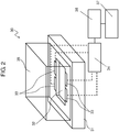
- FIG. 2 is a perspective view of electrochemical measuring apparatus 30 in accordance with this exemplary embodiment.
- FIG. 3 is a schematic sectional view of electrochemical measuring device 10 in accordance with this exemplary embodiment.
- FIG. 3 is a sectional view taken on line 3-3 of FIG. 1 .
- FIG. 4 is a schematic top view of the electrochemical measuring device in accordance with this exemplary embodiment.
- Electrochemical measuring device 10 is a device for measuring an activity state of biological sample 101, for example, a cell or tissue, such as an embryo.
- Electrochemical measuring device 10 includes container 11 and electrode chip 12.
- Container 11 includes upper container 11a and lower container 11b.
- Container 11 has electrode chip 12 packaged inside container 11.
- Container 11 includes reservoir portion 13 for holding measuring liquid 102.
- the bottom surface of reservoir portion 13 is provided with a plurality of inverted cone-shaped wells 14.
- Biological sample 101 is disposed in each well 14.
- Container 11 is produced by, for example, resin molding.
- Electrode chip 12 has region 15 and working electrode 16. Region 15 is a place in which biological sample 101 is disposed. Working electrode 16 is used for electrochemical measurement of biological sample 101.
- Region 15 is, for example, a recess portion provided at the upper surface of electrode chip 12. Note here that region 15 is not limited to a recess portion of electrode chip 12. For example, region 15 may be a part of a plane of electrode chip 12.
- a plurality of working electrodes 16 surrounds the periphery of region 15. This configuration can keep a distance between biological sample 101 disposed in region 15 and working electrodes 16 constant.
- electrochemical measuring device 10 can carry out electrochemical measurement at a plurality of positions whose distances from biological samples 101 are different.
- Electrode chip 12 In electrochemical measuring device 10, lower container 11b, electrode chip 12, and upper container 11a are sequentially stacked.
- Well 14 has through hole 53 on the bottom part thereof. Through hole 53 penetrates through the lower part of upper container 11a. With this configuration, working electrode 16 of electrode chip 12 is exposed at the bottom part of well 14.
- connection terminal 17 is electrically connected to working electrode 16.
- Connection terminal 17 is coupled to measuring instrument such as electrochemical measuring apparatus 30.
- Sealing member 18 is provided between container 11 and electrode chip 12 in order to suppress leakage of measuring liquid 102.
- working electrode 16 may be provided at region 15.
- connection terminal 17 may be formed in any place in container 11 as long as it is electrically connected to working electrode 16.
- the bottom surface of well 14 may not have through hole 53, and the bottom surface of well 14 may be closed.
- Region 15 and working electrode 16 may be provided not on electrode chip 12, but directly on the bottom surface of well 14 of container 11. In this case, electrode chip 12 is not required to be used.
- Electrochemical measuring apparatus 30 carries out electrochemical measurement of a biological sample using electrochemical measuring device 10. Electrochemical measuring apparatus 30 carries out, for example, application of a voltage to working electrode 16 and measurement of a current flowing in working electrode 16.
- Electrochemical measuring apparatus 30 includes stage 31, mounting portion 32, terminals 33, control unit 34, and cover 35.
- Electrochemical measuring device 10 is mounted on mounting portion 32 on stage 31.
- Mounting portion 32 has, for example, a recess portion in the upper surface of stage 31.
- Electrochemical measuring device 10 is fixed to the recess portion of mounting portion 32.
- Stage 31 is provided with terminals 33. Terminals 33 are brought into contact with connection terminal 17 of electrochemical measuring device 10. Thus, working electrode 16 is electrically connected to terminals 33. Furthermore, terminals 33 are electrically connected to control unit 34.
- Control unit 34 controls magnitude of a voltage applied to the working electrode and timing at which the voltage is applied.
- Control unit 34 includes a power circuit, a voltage-applying circuit, and the like.
- control unit 34 can generate a command signal to apply a voltage and can apply a voltage to the working electrode.
- electrochemical measuring apparatus 30 may include measurement unit 36 and operation unit 37.
- Measurement unit 36 measures, for example, a current flowing in working electrode 16 by the applied voltage.
- Operation unit 37 calculates, for example, an activity degree of biological sample 101 based on the measured current value.
- control unit 34, measurement unit 36, and operation unit 37 may be configured by independent circuits, respectively.
- control unit 34, measurement unit 36, and operation unit 37 may be configured by one integrated circuit (IC).
- IC integrated circuit
- Cover 35 is provided in order to keep a measurement environment of biological sample 101 appropriate. In other words, cover 35 forms a measurement environment isolated from the outside air. Providing cover 35 allows electrochemical measuring apparatus 30 to measure biological sample 101 in an appropriate environment.
- Cover 35 is provided above stage 31. Electrochemical measuring device 10 mounted on mounting portion 32 is completely covered with cover 35.
- electrochemical measuring apparatus 30 may be provided with a supply port for supplying carbon dioxide, a temperature sensor, a heater, and the like.
- Biological sample 101 is, for example, an embryo.
- the embryo includes undifferentiated and cleavage fertilized eggs.
- Electrochemical measuring apparatus 30 can measure the amount of oxygen dissolved in the vicinity of an embryo by the use of working electrode 16. Then, an activity state of oxygen consumption by the embryo can be assessed based on the measured amount of oxygen.
- Reservoir portion 13 is provided with reference electrode 23 and counter electrode 24.
- Measuring liquid 102 is filled into reservoir portion 13 and well 14 such that measuring liquid 102 is in contact with working electrode 16, reference electrode 23, and counter electrode 24.
- Working electrode 16 reference electrode 23, and counter electrode 24 are electrically connected to electrochemical measuring apparatus 30.
- Control unit 34 and measurement unit 36 of electrochemical measuring apparatus 30 are, for example, a potentiostat.
- the potentiostat is an instrument for making electric potential of working electrode 16 with respect to reference electrode 23 constant.
- Biological sample 101 is disposed in region 15 formed in the upper surface of electrode chip 12.
- oxygen-reduction potential is applied to working electrode 16 by the use of a potentiostat.
- oxygen dissolved in the vicinity of working electrode 16 is reduced. Reduction of oxygen allows a current to flow in working electrode 16. The current flowing in working electrode 16 is measured by the potentiostat.
- a value of a current flowing in working electrode 16 is correlated with the amount of oxygen dissolved in the vicinity of working electrode 16. Therefore, measurement of the value of a current in working electrode 16 disposed in the vicinity of biological sample 101 permits estimation of a dissolved oxygen concentration (an amount of dissolved oxygen) as the substance concentration in the vicinity of biological sample 101.
- counter electrode 24 may not be provided. That is to say, reference electrode 23 may have a function as counter electrode 24 in addition to the function as reference electrode 23.
- FIG. 5 is a flowchart showing an electrochemical measuring method in accordance with this exemplary embodiment.
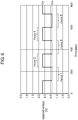
- FIG. 6 shows a voltage application protocol showing one example of application timing of a voltage to be applied to working electrode 16.
- single biological sample 101 is one cell, one cell aggregation, and one tissue.
- the single biological sample 101 does not include a plurality of cells contained in a state in which they are distributed in measuring liquid 102.
- a plurality of working electrodes 16 is provided on the upper surface of electrode chip 12.
- Working electrodes 16 are disposed at different distances from the center of region 15, respectively.
- the electrochemical measuring method in accordance with this exemplary embodiment includes a step of injecting measuring liquid 102 into container 11 (S010); a step of applying measuring voltage Vm to working electrode 16 and measuring a value of first current I 1 in a blank state before biological sample 101 is introduced (S020); a step of applying non-measuring voltage Vn to working electrode 16 (S025); a step of introducing biological sample 101 (S030); a step of applying measuring voltage Vm to working electrode 16 and measuring a value of second current I 2 after biological sample 101 is introduced (S040); a step of applying non-measuring voltage Vn to working electrode 16 (S045); a step of recovering biological sample 101 (S050); a step of applying measuring voltage Vm to working electrode 16, and measuring a value of third current I 3 in a blank state after biological sample 101 is recovered (S060); and a step of calculating a dissolved oxygen concentration (an amount of dissolved oxygen) as a substance concentration in measuring liquid 102 from the measured current values I
- step S010 measuring liquid 102 is injected into reservoir portion 13 and well 14 of container 11. Measuring liquid 102 is in contact with working electrode 16, reference electrode 23, and counter electrode 24. Then, electrochemical measuring device 10 is mounted on mounting portion 32 of electrochemical measuring apparatus 30. At this time, connection terminal 17 is in contact with terminal 33.
- working electrode 16 and counter electrode 24 are described using a platinum electrode.
- reference electrode 23 is described using a silver-silver chloride electrode. However, the electrode material is not limited to these materials.
- procedure may be started from step S020.
- measuring voltage Vm is applied to working electrode 16, and a value of first current I 1 before biological sample 101 is introduced is measured.
- Measuring voltage Vm is applied in period 1 shown in FIG. 6 .
- Measuring voltage Vm is at oxygen-reduction potential.
- measuring voltage Vm is, for example, -0.6 V.
- period 1 is a period from 120th second to 240th second.
- Period 1 is preferably 10 seconds or more and 120 seconds or less. Note here that for the purpose of shortening the measurement time of the electrochemical measurement, period 1 may be 5 seconds or more and 10 seconds or less.
- non-measuring voltage Vn is applied.
- measuring voltage Vm is a voltage to be applied at the time of measurement.
- Non-measuring voltage Vn is a voltage to be applied so as to prevent a current from flowing in the electrode.
- Measurement unit 36 measures a value of first current I 1 flowing in working electrode 16.
- step S020 it is possible to measure the value of first current I 1 resulting from the dissolved oxygen concentration (the amount of dissolved oxygen) included in measuring liquid 102 in a blank state, which is not influenced by biological sample 101.
- non-measuring voltage Vn is applied to working electrode 16. Then, in step S030, biological sample 101 is introduced. Non-measuring voltage Vn is applied in period 2 shown in FIG. 6 .
- Non-measuring voltage Vn is an open-circuit voltage of electrochemical measuring apparatus 30. In this exemplary embodiment, non-measuring voltage Vn is, for example, 0.2 V.
- period 2 is a period from 240th second to 360th second. Period 2 is preferably 30 seconds or more and 120 seconds or less.
- Biological sample 101 is disposed in region 15 with non-measuring voltage Vn applied to working electrode 16. In region 15, one biological sample 101 is disposed. Since a current does not flow in working electrode 16, it is possible to suppress current noise when biological sample 101 is disposed in region 15.
- step S040 a value of second current I 2 after biological sample 101 is introduced is measured.
- Measuring voltage Vm is applied in period 3 shown in FIG. 6 .
- Measuring voltage Vm is at oxygen-reduction potential.
- measuring voltage Vm is, for example, -0.6 V.
- period 3 is a period from 360th second to 480th second.
- Period 3 is preferably 10 seconds or more and 120 seconds or less. Note here that for the purpose of shortening the measurement time in the electrochemical measurement, period 1 may be 5 seconds or more and 10 seconds or less.
- step S040 it is possible to measure a value of second current I 2 resulting from the dissolved oxygen concentration (the amount of dissolved oxygen), which is influenced by respiration activity of biological sample 101.
- Biological sample 101 disposed in region 15 consumes the dissolved oxygen in the vicinity in measuring liquid 102 with the respiration activity. Consequently, in the vicinity of biological sample 101 in measuring liquid 102, oxygen decreases. Furthermore, the dissolved oxygen in measuring liquid 102 is nearer to an oxygen saturation state of measuring liquid 102 as a distance from biological sample 101 increases.
- the respiration activity of biological sample 101 is more active, a larger amount of oxygen is consumed in the vicinity of biological sample 101. That is to say, the size of the oxygen concentration gradient in the vicinity of biological sample 101 is determined by the amount of respiration activity of a fertilized egg as biological sample 101.
- non-measuring voltage Vn is applied to working electrode 16.
- biological sample 101 is recovered.
- Non-measuring voltage Vn is applied in period 4 shown in FIG. 6 .
- Non-measuring voltage Vn is an open-circuit voltage of entire electrochemical measuring apparatus 30 including a measuring instrument coupled to electrochemical measuring device 10. At this time, electrochemical measuring device 10 is filled with measuring liquid 102.
- non-measuring voltage Vn is, for example, 0.2 V.
- period 4 is a period from 480th second to 600th second. Period 4 is preferably 30 seconds or more and 120 seconds or less.
- Biological sample 101 is taken out from measuring liquid 102 with non-measuring voltage Vn applied to working electrode 16. At this time, since a current does not flow in working electrode 16, it is possible to suppress current noise when biological sample 101 is taken out.
- biological sample 101 can be prevented from being damaged.
- measuring voltage Vm is applied to working electrode 16 and a value of third current I 3 after biological sample 101 is recovered is measured.
- Measuring voltage Vm is applied in period 5 shown in FIG. 6 .
- Measuring voltage Vm is at oxygen-reduction potential.
- measuring voltage Vm is, for example, -0.6 V.
- period 5 is a period from 600th second to 720th second.
- Period 5 is preferably 10 seconds or more and 120 seconds or less. Note here that for the purpose of shortening the measurement time of the electrochemical measurement, period 1 may be 5 seconds or more and 10 seconds or less.
- Measurement unit 36 measures a value of third first current I 3 flowing in working electrode 16.
- step S060 it is possible to measure a value of third current I 3 resulting from the dissolved oxygen concentration contained in measuring liquid 102 in a blank state, which is not directly influenced by biological sample 101.
- measuring voltages Vm in step S020, step S040 and step S060 are the same value. Furthermore, it is preferable that non-measuring voltages Vn in step S030 and step S050 are the same value.
- period 1, period 3 and period 5 have the same time. Furthermore, it is preferable that period 2 and period 4 have the same time.
- step S070 the dissolved oxygen concentration (the amount of dissolved oxygen) is calculated from the measured values of first current I 1 , second current I 2 , and third current I 3 .
- step S040 as biological sample 101 consumes oxygen, the concentration of the dissolved oxygen becomes low in the vicinity of biological sample 101. Furthermore, as the distance from biological sample 101 increases, the influence of biological sample 101 on the dissolved oxygen in measuring liquid 102 decreases.
- step S040 the current change rate I* 2 of working electrode 16 in the vicinity of biological sample 101 increases. Furthermore, as the distance from biological sample 101 increases, the current change rate I* 2 of working electrode 16 decreases.
- the current change rate I* 2 in each working electrode 16 is in reverse proportion to the distance from biological sample 101 in each working electrode 16.
- the slope of a straight line obtained by plotting the current change rate I* 2 in each working electrode 16 with respect to the inverse of the distance from biological sample 101 shows an oxygen concentration gradient formed corresponding to the consumption of oxygen by biological sample 101.
- C 0 represents a bulk concentration of dissolved oxygen.
- the bulk concentration of dissolved oxygen denotes a concentration of dissolved oxygen contained in measuring liquid 102 in a state in which biological sample 101 is not included.
- r represents a radius of biological sample 101.
- R represents a distance from the center of biological sample 101 to the center of working electrode 16. Note here that the center of biological sample 101 may be the center of region 15.
- D is a diffusion coefficient of the dissolved oxygen in measuring liquid 102.
- the concentration gradient of dissolved oxygen and the oxygen flux in step S020 and step S060 are also calculated in the same manner as mentioned above. That is to say, the concentration gradient of dissolved oxygen and the flow rate of oxygen in each step are calculated by using the values of first current I 1 , second current I 2 , and third current I 3 . From the size of the flow rate of oxygen in step S040, the activity of biological sample 101 is measured.
- the oxygen flux may be formed inside well 14.
- the oxygen flux calculated in step S040 may be corrected by the oxygen flux in a blank state in step S020 and step S060.
- the substance concentration to be calculated is not necessarily limited to the dissolved oxygen concentration.
- the substance concentration may be a concentration of a substance showing activity of biological sample 101.
- the electrochemical measurement of biological sample 101 may be carried out by a part of steps of the electrochemical measuring method in accordance with this exemplary embodiment. For example, only the values of the first and second currents may be measured, and the values of the second and third currents may be measured without measuring the value of the first current.
- control unit 34 of electrochemical measuring apparatus 30 carries out a step of applying measuring voltage Vm to working electrode 16 and measuring a value of first current I 1 before biological sample 101 is introduced; a step of applying non-measuring voltage Vn to working electrode 16 at the timing before biological sample 101 is introduced into electrochemical measuring device 10; a step of applying measuring voltage Vm to working electrode 16 and measuring a value of second current I 2 after biological sample 101 is introduced; a step of applying non-measuring voltage Vn to working electrode 16 at the timing before biological sample 101 is recovered from electrochemical measuring device 10; and a step of applying measuring voltage to working electrode 16, and measuring a value of third current I 3 after recovering biological sample 101.
- FIG. 7 is a graph showing a voltage application protocol in accordance with modification Example 1 of the first exemplary embodiment.
- This modification example is different from the above-mentioned exemplary embodiment in the application method of measuring voltage Vm in periods 1, 3 and 5.
- measuring voltage Vm is applied in a pulse-like waveform. That is to say, for example, in period 1 of step S020, measuring voltage Vm and non-measuring voltage Vn are alternately applied to working electrode 16, repeatedly. The same is true in periods 3 and 5.
- application time of measuring voltage Vm in one pulse is preferably one second or more and 10 seconds or less.
- pulse waveform is given at least twice. In example shown in FIG. 7 , in period 1, measuring voltage Vm is applied three times. The application time of measuring voltage Vm is 5 seconds.
- the application time of non-measuring voltage Vn between measuring voltages Vm is one second or more and 25 seconds or less.
- the application time of non-measuring voltage Vn may be equal to that of measuring electric potential Vm.
- the application time of non-measuring electric potential Vn may be five seconds.
- pulse waveforms of the voltages applied in periods 1, 3 and period 5 are equal to each other. That is to say, it is preferable that the pulse widths and time periods of voltage waveforms shown in FIG. 6 are equal to each other.
- the waveform of a current to be measured also becomes a pulse-like waveform.
- the other current value may be normalized.
- the normalized oxygen-reduction current value can be obtained.
- Applying of a pulse-like voltage can shorten integrated time of voltage application in a state in which biological sample 101 is disposed in region 15.
- Shortening of the integrated time of the applied voltage can suppress accumulation of reduced product generated by reduction of oxygen on the surface of working electrode 16.
- it is possible to suppress the decrease over time of a value of current flowing in working electrode 16.
- it is possible to decrease the influence to be exerted on biological sample 101 by the reduced product.
- FIG. 8 is a flowchart showing an electrochemical measuring method in accordance with this modification example.
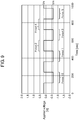
- FIG. 9 is a graph showing a voltage application protocol in accordance with modification Example 2 of this exemplary embodiment.
- This modification example is different from the exemplary embodiment in that period 10 during which measuring voltage Vm is applied is further provided before period 1.
- the electrochemical measuring method of this modification example includes step S015 of stabilizing a value of current flowing in working electrode 16 before step S020 of measuring a value of first current I 1 .
- Step S015 is carried out after step S010 of injecting measuring liquid into container 11.
- step S015 measuring voltage Vm is applied to working electrode 16. Measuring voltage Vm is applied in period 10.
- step S015 After step S015 is carried out, measurement later than step S020 is carried out sequentially.
- Period 10 is time necessary for working electrode 16 to be stabilized. Furthermore, the application time of measuring voltage Vm may be determined while the value of a current flowing in working electrode 16 is monitored.
- the value of a current flowing in working electrode 16 is stabilized when a voltage is applied to working electrode 16 for a while, so that the value of current is decreased to some extent. In this way, the state of working electrode 16 can be stabilized.
- step S015 allows abnormality of working electrode 16 and the measuring instrument to be detected before measurement in step S020. Then, when abnormality occurs, an error can be displayed on a display unit and the like (not shown) based on the oxygen-reduction current obtained in step S015.
- measuring voltage Vm applied to working electrode 16 in step S015 may be a constant voltage or may be a pulse-like voltage.
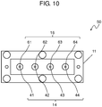
- FIG. 10 is a top view of electrochemical measuring device 50 in accordance with this exemplary embodiment.
- This exemplary embodiment is different from the first exemplary embodiment in that this exemplary embodiment provides a measuring method for measuring a plurality of biological samples 101 provided in electrochemical measuring device 50 in parallel.
- Electrochemical measuring device 50 includes a plurality of wells 41, 42, 43, and 44 in reservoir portion 13.
- well 41, 42, 43, and 44 are collectively referred to as well 14.
- the number of wells 14 is two or more and six or less.
- Electrode chip 12 is disposed under each well 14.
- Working electrode 61 is provided at well 41.
- Working electrode 62 is provided at well 42.
- Working electrode 63 is provided at well 43.
- Working electrode 64 is provided at well 44.
- working electrodes 61, 62, 63, and 64 are collectively referred to as working electrode 16.
- An operation method of electrochemical measuring device 50 in accordance with this exemplary embodiment is the same as in the first exemplary embodiment.
- FIG. 11 is a flowchart showing an electrochemical measuring method in accordance with this exemplary embodiment.
- a method for measuring activity states of a plurality of biological samples 101 in accordance with the second exemplary embodiment is described.
- the electrochemical measuring method in accordance with this exemplary embodiment includes a step of injecting measuring liquid 102 into container 11 (S100); a step of applying measuring voltage Vm to each of working electrodes 16 and measuring a value of first current I 1X in a blank state before biological sample 101 is introduced in each well 14 (S200); a step of applying non-measuring voltage Vn to each of working electrodes 16 (S250); a step of introducing one each of a plurality of biological samples 101 into each well 14 (S300); a step of applying measuring voltage Vm to each of working electrodes 16 and measuring a value of second current I 2x after biological sample 101 is introduced in each well 14 (S400); a step of applying non-measuring voltage Vn to each of working electrodes 16 (S450); a step of recovering biological sample 101 from each well 14 (S500); a step of applying measuring voltage Vm to each of working electrodes 16, and measuring a value of third current I 3X in a blank state after biological sample 101 is recovered in each well 14 (S600
- FIG. 12 is a graph showing a voltage application protocol in accordance with this exemplary embodiment.
- FIG. 13 is a graph showing an enlarged period 11 in FIG. 12 .
- step S100 measuring liquid 102 is injected into container 11.
- step S200 measuring voltage Vm is sequentially applied to working electrodes 16 disposed in each of a plurality of wells 14, and the value of first current I 1x before biological sample 101 is introduced is measured in working electrodes 16 of a plurality of wells 14.
- the value of first current I 1x shows each current value in each well 14.
- Measuring voltage Vm is applied to working electrodes 16 in period 11.
- the voltage application protocol shown in FIG. 13 measures the value of first current I 1x flowing in working electrode 16 of each well once in period 11.
- Period 11 includes periods A, B, C, and D.
- measuring voltage Vm is applied to working electrode 61 disposed in one well 41 of the plurality of wells 14.
- a value of first current In flowing in working electrode 61 in well 41 is applied to working electrode 61 disposed in one well 41 of the plurality of wells 14.
- measuring voltage Vm is applied to working electrode 62 disposed in one well 42 of the plurality of wells 14.
- a value of first current I 12 flowing in working electrode 62 in well 42 is applied to working electrode 62 disposed in one well 42 of the plurality of wells 14.
- measuring voltage Vm is applied to working electrode 63 disposed in one well 43 of the plurality of wells 14.
- a value of first current I 13 flowing in working electrode 63 in well 43 is applied to working electrode 63 disposed in one well 43 of the plurality of wells 14.
- measuring voltage Vm is applied to working electrode 64 disposed in one well 44 of the plurality of wells 14.
- a value of first current I 14 flowing in working electrode 64 in well 44 is applied to working electrode 64 disposed in one well 44 of the plurality of wells 14.
- measuring voltage Vm applied to working electrode 16 is a pulse-like voltage. Note here that in each period, measuring voltage Vm applied to working electrode 16 may be a constant voltage.
- step S250 non-measuring voltage Vn is applied to each of working electrodes 16. Then, in step S300, each one of a plurality of biological samples 101 is introduced into each of the plurality of wells 14. Non-measuring voltage Vn is applied to working electrode 16 in period 12.
- step S400 measuring voltage Vm is applied sequentially to each working electrode 16 disposed in each of the plurality of wells 16, a value of second current I 2x after biological sample 101 is introduced is measured in working electrode 16 of each of a plurality of wells 14.
- a value of second current I 2x shows each current value in each well 14.
- Measuring voltage Vm is applied to working electrodes 16 in period 13.
- step S400 measuring voltage Vm is applied to working electrode 16 by the same voltage applying method in step S200.
- a value of second current I 2x can be measured.
- step S450 non-measuring voltage Vn is applied to each of working electrodes 16. Then, in step S500, a plurality of biological samples 101 is recovered. Non-measuring voltage Vn is applied to working electrode 16 in period 14.
- step S600 measuring voltage Vm is applied sequentially to working electrodes 16 respectively disposed in the plurality of wells 14, and a value of third current I 3X after biological sample 101 is recovered in working electrode 16 of each of well 14.
- the value of third current I 3X shows each current value in each well 14.
- Measuring voltage Vm is applied to working electrodes 16 in period 15.
- step S600 measuring voltage Vm is applied to working electrodes 16 by the same voltage applying method as in step S200.
- the value of third current I 3x can be measured.
- step S700 the dissolved oxygen concentration (amount of dissolved oxygen) in measuring liquid 102 of each well 14 is calculated from the measured current values I 1X , I 2X , and I 3X .
- FIG. 14 is a graph showing another voltage application protocol in accordance with this exemplary embodiment.
- steps S200, S400 and S600 an operation of sequentially applying measuring voltage Vm to working electrodes 16 respectively disposed in the plurality of wells 14 is repeated a plurality of times.
- the value of first current I 1x , a value of second current I 2x and a value of third current I 3X are measured. That is to say, in measurement of current value in each step, the periods A to D are repeated a plurality of times.
- Control unit 34 measures voltage Vm to be applied to working electrode 16 of each well 14 by switching working electrodes 16 for each pulse. In this way, by switching of wells for each pulse, time interval for measurement of well 14 in blank measurement and that in measurement of activity of biological sample in step S400, step S200, and S600 can be substantially the same. Note here that measuring voltage Vm to be applied to working electrode 16 in each period of one operation is not limited to one pulse, and may be a plurality of pulse waveforms.
- the total number of pulses is a multiple of the number of fertilized eggs to be measured.
- the number of pulses and pulse width of measuring voltage Vm to be applied to working electrode 61 are equal to the number of pulses and a pulse width of measuring voltage Vm to be applied to the other working electrodes 62, 63, and 64.
- the electrochemical measuring method and the electrochemical measuring apparatus in accordance with one or a plurality of embodiments are described based on the exemplary embodiments.
- the present disclosure is not limited to this exemplary embodiments.
- the electrochemical measuring method may be a program to be executed.
- the electrochemical measuring method and the electrochemical measuring apparatus in accordance with the present disclosure can suppress a current noise generated according to introduction or recovery of a biological sample.
- An electrochemical measuring method and an electrochemical measuring apparatus of the present disclosure are useful for measurement of an activity state of substances of biological origin, such as a fertilized egg and a cell.
Landscapes
- Life Sciences & Earth Sciences (AREA)
- Health & Medical Sciences (AREA)
- Chemical & Material Sciences (AREA)
- Engineering & Computer Science (AREA)
- Physics & Mathematics (AREA)
- Organic Chemistry (AREA)
- Analytical Chemistry (AREA)
- Immunology (AREA)
- Molecular Biology (AREA)
- General Health & Medical Sciences (AREA)
- Biochemistry (AREA)
- Biomedical Technology (AREA)
- Zoology (AREA)
- Wood Science & Technology (AREA)
- Proteomics, Peptides & Aminoacids (AREA)
- Pathology (AREA)
- Biophysics (AREA)
- General Physics & Mathematics (AREA)
- Bioinformatics & Cheminformatics (AREA)
- General Engineering & Computer Science (AREA)
- Biotechnology (AREA)
- Microbiology (AREA)
- Electrochemistry (AREA)
- Chemical Kinetics & Catalysis (AREA)
- Genetics & Genomics (AREA)
- Urology & Nephrology (AREA)
- Medicinal Chemistry (AREA)
- Optics & Photonics (AREA)
- Food Science & Technology (AREA)
- Hematology (AREA)
- Apparatus Associated With Microorganisms And Enzymes (AREA)
- Measuring Or Testing Involving Enzymes Or Micro-Organisms (AREA)
Applications Claiming Priority (3)
| Application Number | Priority Date | Filing Date | Title |
|---|---|---|---|
| US201462055185P | 2014-09-25 | 2014-09-25 | |
| JP2015065869 | 2015-03-27 | ||
| PCT/JP2015/004752 WO2016047114A1 (fr) | 2014-09-25 | 2015-09-17 | Procédé de mesure électrochimique et dispositif de mesure électrochimique |
Publications (2)
| Publication Number | Publication Date |
|---|---|
| EP3199637A1 true EP3199637A1 (fr) | 2017-08-02 |
| EP3199637A4 EP3199637A4 (fr) | 2017-10-04 |
Family
ID=55580661
Family Applications (1)
| Application Number | Title | Priority Date | Filing Date |
|---|---|---|---|
| EP15845383.7A Withdrawn EP3199637A4 (fr) | 2014-09-25 | 2015-09-17 | Procédé de mesure électrochimique et dispositif de mesure électrochimique |
Country Status (5)
| Country | Link |
|---|---|
| US (1) | US10619179B2 (fr) |
| EP (1) | EP3199637A4 (fr) |
| JP (2) | JP6078799B2 (fr) |
| CN (1) | CN106661605B (fr) |
| WO (1) | WO2016047114A1 (fr) |
Cited By (1)
| Publication number | Priority date | Publication date | Assignee | Title |
|---|---|---|---|---|
| EP3553511A4 (fr) * | 2016-12-07 | 2019-12-25 | Panasonic Intellectual Property Management Co., Ltd. | Procédé de mesure électrochimique et dispositif de mesure électrochimique |
Families Citing this family (4)
| Publication number | Priority date | Publication date | Assignee | Title |
|---|---|---|---|---|
| CN106164243B (zh) * | 2014-03-31 | 2018-04-27 | 松下知识产权经营株式会社 | 电化学测定器件 |
| CN107849510A (zh) * | 2015-10-22 | 2018-03-27 | 松下知识产权经营株式会社 | 电化学测定器件以及电化学测定系统 |
| US10837936B2 (en) * | 2016-03-11 | 2020-11-17 | Panasonic Intellectual Property Management Co., Ltd. | Electrochemical measurement system, electrochemical measurement device, and electrochemical measurement method |
| JP2021073920A (ja) * | 2019-11-11 | 2021-05-20 | コニカミノルタ株式会社 | 測定方法および測定装置。 |
Family Cites Families (12)
| Publication number | Priority date | Publication date | Assignee | Title |
|---|---|---|---|---|
| GB8817421D0 (en) * | 1988-07-21 | 1988-08-24 | Medisense Inc | Bioelectrochemical electrodes |
| US6814845B2 (en) * | 2001-11-21 | 2004-11-09 | University Of Kansas | Method for depositing an enzyme on an electrically conductive substrate |
| JP4530991B2 (ja) | 2003-04-11 | 2010-08-25 | 独立行政法人理化学研究所 | マイクロインジェクション方法および装置 |
| JP2005156543A (ja) * | 2003-11-05 | 2005-06-16 | Toto Ltd | 電気化学的測定方法および装置 |
| US7462512B2 (en) * | 2004-01-12 | 2008-12-09 | Polytechnic University | Floating gate field effect transistors for chemical and/or biological sensing |
| US7749371B2 (en) * | 2005-09-30 | 2010-07-06 | Lifescan, Inc. | Method and apparatus for rapid electrochemical analysis |
| JP4343894B2 (ja) * | 2005-11-15 | 2009-10-14 | 株式会社日立製作所 | 生体物質測定装置及び測定方法 |
| JP5393657B2 (ja) * | 2007-05-04 | 2014-01-22 | テセラ, エルエルシー | パッチクランプシステムにおける使用のためのサブシステムおよび方法 |
| JP2010121948A (ja) * | 2008-11-17 | 2010-06-03 | Tohoku Univ | 受精卵の呼吸活性測定装置および受精卵の呼吸活性測定方法 |
| US9476849B2 (en) * | 2009-05-29 | 2016-10-25 | Panasonic Healthcare Holdings Co., Ltd. | Biosensor system and method for measuring concentration of analyte |
| CN102472722A (zh) * | 2009-07-17 | 2012-05-23 | 国立大学法人北海道大学 | 利用cnt传感器对过氧化物进行电测定的方法 |
| JP2014110780A (ja) * | 2012-10-29 | 2014-06-19 | Panasonic Healthcare Co Ltd | 微生物数測定装置および微生物数測定方法 |
-
2015
- 2015-09-17 CN CN201580042601.1A patent/CN106661605B/zh not_active Expired - Fee Related
- 2015-09-17 JP JP2016549947A patent/JP6078799B2/ja not_active Expired - Fee Related
- 2015-09-17 EP EP15845383.7A patent/EP3199637A4/fr not_active Withdrawn
- 2015-09-17 US US15/329,293 patent/US10619179B2/en not_active Expired - Fee Related
- 2015-09-17 WO PCT/JP2015/004752 patent/WO2016047114A1/fr not_active Ceased
-
2016
- 2016-12-16 JP JP2016243908A patent/JP6589139B2/ja not_active Expired - Fee Related
Cited By (1)
| Publication number | Priority date | Publication date | Assignee | Title |
|---|---|---|---|---|
| EP3553511A4 (fr) * | 2016-12-07 | 2019-12-25 | Panasonic Intellectual Property Management Co., Ltd. | Procédé de mesure électrochimique et dispositif de mesure électrochimique |
Also Published As
| Publication number | Publication date |
|---|---|
| JP2017090465A (ja) | 2017-05-25 |
| US10619179B2 (en) | 2020-04-14 |
| JP6589139B2 (ja) | 2019-10-16 |
| CN106661605A (zh) | 2017-05-10 |
| WO2016047114A1 (fr) | 2016-03-31 |
| EP3199637A4 (fr) | 2017-10-04 |
| CN106661605B (zh) | 2020-10-20 |
| JPWO2016047114A1 (ja) | 2017-04-27 |
| JP6078799B2 (ja) | 2017-02-15 |
| US20170218423A1 (en) | 2017-08-03 |
Similar Documents
| Publication | Publication Date | Title |
|---|---|---|
| EP3199637A1 (fr) | Procédé de mesure électrochimique et dispositif de mesure électrochimique | |
| US6990422B2 (en) | Method of analyzing the time-varying electrical response of a stimulated target substance | |
| RU2012146333A (ru) | Система и способ определения электрохимического аналита | |
| RU2594513C1 (ru) | Система и способ для обнаружения использованных и высохших датчиков | |
| ES2812806T3 (es) | Calibración normalizada de determinaciones de la concentración de analito | |
| KR20070121003A (ko) | 안정한 전압을 분석 시스템에 제공하기 위한 방법 및 장치 | |
| RU2014131248A (ru) | Точное измерение аналита для электрохимической тестовой полоски на основании измеренных физических характеристик образца, содержащего аналит, и производных параметров биосенсора | |
| CN110268256B (zh) | 用于确定至少一种分析物的浓度的方法和装置 | |
| RU2014147984A (ru) | Улучшенные методика и система измерения аналита | |
| US10900929B2 (en) | PH value measuring device comprising in situ calibration means | |
| CN111108374A (zh) | PH传感器和用于pH传感器的校准方法 | |
| EP3435076B1 (fr) | Procédé de mesure électrochimique, appareil de mesure électrochimique et transducteur | |
| US20190277828A1 (en) | Electrochemical measuring method and electrochemical measuring device | |
| US20250020612A1 (en) | Method and sensor for determining a plasma-related analyte concentration in whole blood | |
| ES2715407T3 (es) | Aproximación progresiva de la concentración de un analito de muestra | |
| JP3654694B2 (ja) | 残留塩素測定方法および残留塩素計 | |
| WO2017068778A1 (fr) | Dispositif de mesure électrochimique et système de mesure électrochimique | |
| CN105476645A (zh) | 测量装置、检测方法、电化学传感器和测量系统 | |
| JP2021073920A (ja) | 測定方法および測定装置。 | |
| Ondruch et al. | Simple Electrochemical Analysis of Enzyme Kinetics | |
| HK1206227B (en) | System and method for detecting used and dried sensors | |
| HK1241019A1 (en) | System and method for detecting used and dried sensors |
Legal Events
| Date | Code | Title | Description |
|---|---|---|---|
| STAA | Information on the status of an ep patent application or granted ep patent |
Free format text: STATUS: THE INTERNATIONAL PUBLICATION HAS BEEN MADE |
|
| PUAI | Public reference made under article 153(3) epc to a published international application that has entered the european phase |
Free format text: ORIGINAL CODE: 0009012 |
|
| STAA | Information on the status of an ep patent application or granted ep patent |
Free format text: STATUS: REQUEST FOR EXAMINATION WAS MADE |
|
| 17P | Request for examination filed |
Effective date: 20161222 |
|
| AK | Designated contracting states |
Kind code of ref document: A1 Designated state(s): AL AT BE BG CH CY CZ DE DK EE ES FI FR GB GR HR HU IE IS IT LI LT LU LV MC MK MT NL NO PL PT RO RS SE SI SK SM TR |
|
| AX | Request for extension of the european patent |
Extension state: BA ME |
|
| A4 | Supplementary search report drawn up and despatched |
Effective date: 20170904 |
|
| RIC1 | Information provided on ipc code assigned before grant |
Ipc: C12M 1/42 20060101ALI20170829BHEP Ipc: G01N 33/483 20060101ALI20170829BHEP Ipc: C12M 1/34 20060101ALI20170829BHEP Ipc: C12Q 1/02 20060101AFI20170829BHEP Ipc: G01N 27/416 20060101ALI20170829BHEP |
|
| DAV | Request for validation of the european patent (deleted) | ||
| DAX | Request for extension of the european patent (deleted) | ||
| STAA | Information on the status of an ep patent application or granted ep patent |
Free format text: STATUS: EXAMINATION IS IN PROGRESS |
|
| 17Q | First examination report despatched |
Effective date: 20190430 |
|
| GRAP | Despatch of communication of intention to grant a patent |
Free format text: ORIGINAL CODE: EPIDOSNIGR1 |
|
| STAA | Information on the status of an ep patent application or granted ep patent |
Free format text: STATUS: GRANT OF PATENT IS INTENDED |
|
| INTG | Intention to grant announced |
Effective date: 20230215 |
|
| STAA | Information on the status of an ep patent application or granted ep patent |
Free format text: STATUS: THE APPLICATION IS DEEMED TO BE WITHDRAWN |
|
| 18D | Application deemed to be withdrawn |
Effective date: 20230627 |