EP3199706A1 - Système préfabriqué de vanne à glissières de commande d'eau - Google Patents
Système préfabriqué de vanne à glissières de commande d'eau Download PDFInfo
- Publication number
- EP3199706A1 EP3199706A1 EP17151959.8A EP17151959A EP3199706A1 EP 3199706 A1 EP3199706 A1 EP 3199706A1 EP 17151959 A EP17151959 A EP 17151959A EP 3199706 A1 EP3199706 A1 EP 3199706A1
- Authority
- EP
- European Patent Office
- Prior art keywords
- sluice gate
- fabricated
- gate system
- side panels
- water
- Prior art date
- Legal status (The legal status is an assumption and is not a legal conclusion. Google has not performed a legal analysis and makes no representation as to the accuracy of the status listed.)
- Granted
Links
Images

Classifications
-
- E—FIXED CONSTRUCTIONS
- E02—HYDRAULIC ENGINEERING; FOUNDATIONS; SOIL SHIFTING
- E02C—SHIP-LIFTING DEVICES OR MECHANISMS
- E02C1/00—Locks or dry-docks; Shaft locks, i.e. locks of which one front side is formed by a solid wall with an opening in the lower part through which the ships pass
-
- E—FIXED CONSTRUCTIONS
- E02—HYDRAULIC ENGINEERING; FOUNDATIONS; SOIL SHIFTING
- E02B—HYDRAULIC ENGINEERING
- E02B7/00—Barrages or weirs; Layout, construction, methods of, or devices for, making same
- E02B7/20—Movable barrages; Lock or dry-dock gates
-
- Y—GENERAL TAGGING OF NEW TECHNOLOGICAL DEVELOPMENTS; GENERAL TAGGING OF CROSS-SECTIONAL TECHNOLOGIES SPANNING OVER SEVERAL SECTIONS OF THE IPC; TECHNICAL SUBJECTS COVERED BY FORMER USPC CROSS-REFERENCE ART COLLECTIONS [XRACs] AND DIGESTS
- Y02—TECHNOLOGIES OR APPLICATIONS FOR MITIGATION OR ADAPTATION AGAINST CLIMATE CHANGE
- Y02A—TECHNOLOGIES FOR ADAPTATION TO CLIMATE CHANGE
- Y02A10/00—TECHNOLOGIES FOR ADAPTATION TO CLIMATE CHANGE at coastal zones; at river basins
- Y02A10/30—Flood prevention; Flood or storm water management, e.g. using flood barriers
Definitions
- the present invention relates to sluice gates.
- Sluice gates are used selectively to control water flow from one area of a channel to another by opening or closing off the channel to the water flow.
- the frame/foundation of the sluice gate is cast directly at the application site of the sluice gate.
- the flow of water must be discontinued over the portion of land, where the sluice gate is to be placed, requiring many man hours of preparation before the actual casting process can be initiated.
- the construction time is long, as the cement needs to settle and harden before a sluice gate member can be installed therein.
- the weather conditions may affect the hardening of the cement, resulting in a frame/foundation of poor quality and strength.
- the frame/foundation is susceptible to undermining of the water.
- One aspect relates to a pre-fabricated water control sluice gate system comprising:
- Another aspect relates to a pre-fabricated water control sluice gate system comprising:
- the first frame is a pre-cast concrete frame.
- the first frame is a pre-cast reinforced concrete frame.
- pre-cast as used throughout this application means the opposite of cast in situ.
- the pre-cast reinforced concrete frame is finished as finished structures when shipped to a builder or customer, rather than being poured into temporary forms at the building site or place of use.
- reinforced concrete refers to concrete into which reinforcement bars or fibres have been cast to carry tensile loads in order to strengthen a structure that would otherwise be brittle.
- the first frame may also be made of metal, wood, or a castable material. It is to be understood that any suitable castable material, such as cement, mortar, concrete, ceramics, thermoset plastics, and thermoplastics can be used for producing the first frame.
- the side and/or base panels are made from a reinforced castable material.
- the side and/or base panels are made from a reinforced castable material, and wherein the reinforcement extends beyond the side and/or base panels.
- reinforced castable material refers to a castable material into which reinforcement bars or fibres have been cast to carry tensile loads in order to strengthen a structure that would otherwise be brittle.
- lifting anchor should be broadly construed to encompass any such device for lifting the first frame with or without sluice gate members and actuators installed therein.
- a coupler adapted for receiving a lifting anchor is embedded in the first frame.
- the coupler may comprise internal or external threading, depending on the configuration of the lifting anchor.
- the lifting anchor or coupler adapted for receiving a lifting anchor is mechanically tied into the reinforcing members embedded in the castable material, such as concrete.
- the base panel In order to avoid that water will undermine the base panel; it may be an advantage to extend the base panels beyond the side panels, preferably beyond the front, back and outer side/face of the side panel. In one or more embodiments, the base panel extends beyond the side panels.
- the base panel extends beyond the front of the side panels.
- the base panel extends beyond back of the side panels.
- the base panel extends beyond the outer side/face of the side panels.
- the base panel extends beyond the front and/or the back and/or the outer side of the side panels.
- the part of the base panel extending beyond the side panels comprises channels adapted for receiving an earth anchor.
- the reinforcement extends beyond the side and/or base panels.
- the reinforcement extends beyond the side panels, preferably beyond the front and back of the side panel. This will allow the pre-fabricated sluice gate system to be built into other reinforced concrete structures.
- the reinforcement extends beyond the front of the side panels.
- the reinforcement extends beyond the back of the side panels.
- the reinforcement extends beyond the outer side/face of the side panels.
- the reinforcement extends beyond the front and/or the back and/or the outer side of the side panels.
- a part of the base panel is configured as a lower sluice gate member extending between the two side panels.
- the base panel is preferably pre-cast. This configuration has the advantage, that it increases the strength of the sluice gate against high water levels. A substantial part of the water pressure is thereby withheld by the entire structure of the first frame.
- the lower gate member prevents that water flow passing through the first frame will remove the dirt/foundation below the first frame. The water flow is thereby elevated further away from the dirt/foundation below the first frame; and the water close to the dirt/foundation below the first frame will be stagnant.
- the lower sluice gate member may be positioned in front of the sluice gate members to shield the latter, and/or may be positioned behind the sluice gate members to support the latter.
- the lower sluice gate member has a height of at least 5 cm, such as within the range of 5-100 cm, e.g. within the range of 10-95 cm, such as within the range of 15-90 cm, e.g. within the range of 20-85 cm, such as within the range of 25-80 cm, e.g. within the range of 30-75 cm, such as within the range of 35-70 cm, e.g. within the range of 40-65 cm, such as within the range of 45-60 cm, e.g. within the range of 50-55 cm.
- the lower sluice gate member may in one or more embodiments comprise air/water channels adapted to be connected to a source of water and/or compressed air. Water and/or compressed air may thereby be used to remove sediments blocking the function of the one or more gate members. Icing may also be prevented.
- the outlet of the channels is positioned in close proximity, such as within 0-20 cm, e.g. within 1-15 cm, such as within 2-10 cm, e.g. within 3-5 cm, to the one or more gate members.
- the base panel comprises air/water channels adapted to be connected to a source of water and/or compressed air.
- the pre-fabricated water control sluice gate system further comprises means for delivering water and/or compressed air to the air/water channels.
- the base panel comprises suction channels adapted to be connected to a source of suction.
- the suction channels may be used to remove sediments blocking the function of the one or more gate members. Icing may also be prevented.
- the lower sluice gate member comprises suction channels adapted to be connected to a source of suction.
- the inlet of the suction channels is positioned in close proximity, such as within 0-20 cm, e.g. within 1-15 cm, such as within 2-10 cm, e.g. within 3-5 cm, to the one or more gate members.
- the pre-fabricated water control sluice gate system further comprises a source of suction adapted for being connected to the suction channels.
- the one or more sluice gate members are a flap gate, a mitre gate, a vertical rising gate, a radial sluice gate, a rising sector sluice gate, or a drum sluice gate, a sluice gate comprising a cylindrical surface, or combinations thereof.
- the inner side of the side panels each comprise a channel configured for receiving a moving gate member.
- the outer face of the side panels each comprise a channel configured for receiving a reinforcement plate adapted for being imbedded in the adjacent dam section.
- the pre-fabricated water control sluice gate system further comprises a casing adapted for receiving the first frame, the casing comprising two side panels and a base panel, wherein the base panel is adapted for supporting the base panel of the first frame, and wherein each side panel is adapted for supporting a side panel of the first frame.
- the pre-fabricated water control sluice gate system further comprises a casing adapted for receiving the pre-cast reinforced concrete frame, the casing comprising two side panels and a base panel, wherein the base panel is adapted for supporting the base panel of the pre-cast reinforced concrete frame, and wherein each side panel is adapted for supporting a side panel of the pre-cast reinforced concrete frame.
- the casing comprises an opening between its side panels, such that water can flow to and from a sluice gate positioned within the casing.
- the casing comprises an opening between its side panels, such that water can flow to and from a first frame, such as a pre-cast reinforced concrete frame, according to the present invention positioned within the casing.
- the casing comprises a front panel with an opening, and wherein the opening is adapted such that water can flow to a sluice gate positioned within the casing; and wherein the casing further comprises a back panel with an opening, and wherein the opening is adapted such that water can flow from a sluice gate positioned within the casing.
- the casing comprises a front panel with an opening, and wherein the opening is adapted such that water can flow to a sluice gate positioned within the casing.
- the casing comprises a back panel with an opening, and wherein the opening is adapted such that water can flow from a sluice gate positioned within the casing.
- the casing is made of reinforced concrete. In one or more embodiments, the casing is pre-cast.
- the casing comprises at least one lifting anchor or coupler adapted for receiving a lifting anchor, preferably one or more pairs of lifting anchors or couplers adapted for receiving a lifting anchor to provide a stable lift.
- the base panel In order to avoid that water will undermine the base panel; it may be an advantage to extend the base panels beyond the side panels, preferably beyond the front, back and outer side/face of the side panel. In one or more embodiments, the base panel extends beyond the side panels.
- the base panel of the casing extends beyond the front of the side panels.
- the base panel of the casing extends beyond back of the side panels.
- the base panel of the casing extends beyond the outer side/face of the side panels.
- the base panel of the casing extends beyond the front and/or the back and/or the outer side of the side panels.
- the part of the base panel of the casing extending beyond the side panels comprises channels adapted for receiving an earth anchor.
- the reinforcement extends beyond the side panels of the casing, preferably beyond the front and back of the side panel. This will allow the pre-fabricated sluice gate system to be built into other reinforced concrete structures.
- the reinforcement extends beyond the front of the side panels of the casing.
- the reinforcement extends beyond the back of the side panels of the casing.
- the reinforcement extends beyond the outer side/face of the side panels of the casing.
- the reinforcement extends beyond the front and/or the back and/or the outer side of the side panels of the casing.
- the outer face of the side panels each comprise a channel configured for receiving a reinforcement plate adapted for being imbedded in the adjacent dam section.
- a second aspect relates to a pre-cast reinforced concrete frame for a water control sluice gate system comprising:
- a third aspect relates to a first frame for a water control sluice gate system comprising:
- the base panel extends beyond the side panels, and wherein the part of the base panel extending beyond the side panels comprises channels adapted for receiving an earth anchor.
- the outer face of the side panels each comprise a channel configured for receiving a reinforcement plate adapted for being imbedded in the adjacent dam section.
- a fourth aspect relates to a method for segregating a body of water into two distinct parts with a pre-fabricated water control sluice gate system comprising the steps of:
- a fifth aspect relates to a method for segregating a body of water into two distinct parts with a pre-fabricated water control sluice gate system comprising the steps of:
- pre-fabricated water control sluice gate systems are constructed of reinforced concrete, but could also be constructed of other materials.
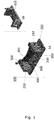
- Figure 1 shows a pre-fabricated water control sluice gate system with two sluice gate members (mitre gate) in accordance with various embodiments of the invention.
- Figure 1A shows the sluice gate member 400 in a closed position
- a Figure 1B shows the sluice gate member in an open position.
- the pre-fabricated water control sluice gate system 100 comprises a pre-cast reinforced concrete frame 200, lifting anchors 300, two sluice gate members 400, and an actuator 500 adapted for moving the sluice gate members 400.
- the pre-cast reinforced concrete frame 200 comprises two pre-cast reinforced concrete side panels 210, and a pre-cast reinforced concrete base panel 220 interconnecting the two side panels 210.
- the side base panel 220 is adapted for mounting the sluice gate members 400 thereto.
- the base panel 220 is shown extending beyond the outer side/face of the side panels 210. Large stones may be placed on this part to keep the pre-cast reinforced concrete frame 200 in place.
- a part of the base panel 220 is configured as a lower gate member 222 extending between the two side panels 210.
- the lower gate member 222 is positioned behind the sluice gate members 400 to support the latter.
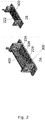
- FIG. 2 shows a pre-fabricated water control sluice gate system with one sluice gate member (flap gate) 400 in accordance with various embodiments of the invention.
- Figure 2A shows the sluice gate member 400 in a closed position
- a Figure 2B shows the sluice gate member in an open position
- the pre-cast reinforced concrete base panel is configured as a lower gate member 222 extending between the two side panels.
- the lower gate member 222 is positioned behind the sluice gate member to support the latter, but also to elevate the water flow away from the dirt/foundation below the base panel. The water close to the dirt/foundation below the base panel will thus be stagnant.
- the lower gate member 222 comprises water/air channels 224 adapted to be connected to a source of water and/or compressed air. Water and/or compressed air may thereby be used to remove sediments blocking the function of the one or more sluice gate members.
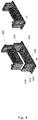
- Figure 3 shows a pre-fabricated water control sluice gate system with one sluice gate member (vertical rising gate) in accordance with various embodiments of the invention.
- Figures 3A (perspective view) and 3B (cross-sectional view) show the sluice gate member 400 in an open position
- Figure 3C (cross-sectional view) shows the sluice gate member in a closed position.
- the pre-cast reinforced concrete base panel 220 is configured as a lower gate member 222 extending between the two side panels.
- the lower gate member 222 is positioned in front of the sluice gate member to elevate the water flow away from the dirt/foundation below the base panel. The water close to the dirt/foundation below the base panel will thus be stagnant.
- the lower gate member 222 may comprise (not shown) water/air channels adapted to be connected to a source of water and/or compressed air. The water/air channel outlets may be positioned on either side of the lower gate member 222.
- the inner side/face 212 of the side panels each comprise a channel 214 configured for receiving a moving gate member 400.
- Figure 4 shows a casing 600 adapted for receiving the pre-cast reinforced concrete frame 200 in accordance with various embodiments of the invention.
- Figure 4A shows the pre-cast reinforced concrete frame 200 about to be inserted into the casing 600
- Figure 4B shows the pre-cast reinforced concrete frame inserted into the casing.
- the casing 600 comprises two side panels 610 and a base panel 620.
- the base panel 620 is adapted for supporting the base panel 220 of the pre-cast reinforced concrete frame 200, and each side panel 610 is adapted for supporting a side panel 210 of the pre-cast reinforced concrete frame 200.
- the reinforcement 630 extends beyond the side panels 610 of the casing 600, here shown beyond the front, back and outer face of the side panel. This will allow the pre-fabricated sluice gate system to be built into other reinforced concrete structures.
- the outer face of the side panels each comprise a channel 640 configured for receiving a reinforcement plate adapted for being imbedded in the adjacent dam section.
Landscapes
- Engineering & Computer Science (AREA)
- General Engineering & Computer Science (AREA)
- Structural Engineering (AREA)
- Mechanical Engineering (AREA)
- Civil Engineering (AREA)
- Ocean & Marine Engineering (AREA)
- Barrages (AREA)
Applications Claiming Priority (2)
| Application Number | Priority Date | Filing Date | Title |
|---|---|---|---|
| DKPA201600057 | 2016-01-28 | ||
| DKPA201600176A DK179455B1 (en) | 2016-03-22 | 2016-03-22 | A prefabricated water control sluice system and a method of segregating a body of water with a prefabricated water control sluice system |
Publications (2)
| Publication Number | Publication Date |
|---|---|
| EP3199706A1 true EP3199706A1 (fr) | 2017-08-02 |
| EP3199706B1 EP3199706B1 (fr) | 2020-04-01 |
Family
ID=57838275
Family Applications (1)
| Application Number | Title | Priority Date | Filing Date |
|---|---|---|---|
| EP17151959.8A Active EP3199706B1 (fr) | 2016-01-28 | 2017-01-18 | Système préfabriqué de vanne à glissières de commande d'eau |
Country Status (1)
| Country | Link |
|---|---|
| EP (1) | EP3199706B1 (fr) |
Cited By (1)
| Publication number | Priority date | Publication date | Assignee | Title |
|---|---|---|---|---|
| EP4012104A1 (fr) | 2020-12-14 | 2022-06-15 | Wintec Holding ApS | Système de commande d'eau préfabriqué |
Citations (6)
| Publication number | Priority date | Publication date | Assignee | Title |
|---|---|---|---|---|
| GB945728A (en) * | 1962-06-22 | 1964-01-08 | Drysdale & Co Ltd | Improvements in or relating to gates for dry docks |
| DE2838431B1 (de) * | 1978-09-02 | 1979-09-20 | Meerestech Seebau Ing Ims | Klapptor zum Sperren von Fluessen,Kanaelen,Docks u.ae. |
| JPS5938409A (ja) * | 1982-08-24 | 1984-03-02 | Ishikawajima Constr Material Co Ltd | コンクリ−ト製水門 |
| BE1004982A5 (fr) * | 1991-06-20 | 1993-03-09 | Frankignoul Pieux Armes | Procede de construction d'une structure de barrage ou de digue et structure obtenue a l'aide de ce procede. |
| NL1037027C2 (nl) * | 2009-06-09 | 2010-12-13 | Jan Joost Schager | Sluis- en/of brughoofd als casco. |
| WO2014158876A1 (fr) * | 2013-03-14 | 2014-10-02 | French Development Enterprises, LLC | Barrage hydroélectrique intelligent à accumulation de puissance |
-
2017
- 2017-01-18 EP EP17151959.8A patent/EP3199706B1/fr active Active
Patent Citations (6)
| Publication number | Priority date | Publication date | Assignee | Title |
|---|---|---|---|---|
| GB945728A (en) * | 1962-06-22 | 1964-01-08 | Drysdale & Co Ltd | Improvements in or relating to gates for dry docks |
| DE2838431B1 (de) * | 1978-09-02 | 1979-09-20 | Meerestech Seebau Ing Ims | Klapptor zum Sperren von Fluessen,Kanaelen,Docks u.ae. |
| JPS5938409A (ja) * | 1982-08-24 | 1984-03-02 | Ishikawajima Constr Material Co Ltd | コンクリ−ト製水門 |
| BE1004982A5 (fr) * | 1991-06-20 | 1993-03-09 | Frankignoul Pieux Armes | Procede de construction d'une structure de barrage ou de digue et structure obtenue a l'aide de ce procede. |
| NL1037027C2 (nl) * | 2009-06-09 | 2010-12-13 | Jan Joost Schager | Sluis- en/of brughoofd als casco. |
| WO2014158876A1 (fr) * | 2013-03-14 | 2014-10-02 | French Development Enterprises, LLC | Barrage hydroélectrique intelligent à accumulation de puissance |
Cited By (1)
| Publication number | Priority date | Publication date | Assignee | Title |
|---|---|---|---|---|
| EP4012104A1 (fr) | 2020-12-14 | 2022-06-15 | Wintec Holding ApS | Système de commande d'eau préfabriqué |
Also Published As
| Publication number | Publication date |
|---|---|
| EP3199706B1 (fr) | 2020-04-01 |
Similar Documents
| Publication | Publication Date | Title |
|---|---|---|
| US20140223851A1 (en) | Prefabricated reinforced concrete wall panel and installation method | |
| CN117144976A (zh) | 一种地下车库顶板后浇带超前施工方法 | |
| EP3199706B1 (fr) | Système préfabriqué de vanne à glissières de commande d'eau | |
| CN109826441B (zh) | 一种用于混凝土结构c型哈芬槽侧向预埋安装方法 | |
| EP3228753B1 (fr) | Système de pompe de commande d'eau préfabriqué modulaire | |
| CN106930391B (zh) | 无模施工顶板现浇排水渠结构及施工方法 | |
| KR101526461B1 (ko) | 기능형 프리캐스트 콘크리트 수로암거 | |
| KR100963488B1 (ko) | 프리캐스트 콘크리트 pc강선 정착블록을 이용한 부모멘트 바닥판 슬래브에 프리스트레스를 도입하는 방법 | |
| KR20050110305A (ko) | 배수판 및 이를 이용한 지하층 바닥시공방법 | |
| US20120005976A1 (en) | Modular foundation system and method | |
| EP3486376B1 (fr) | Système préfabriqué de vanne à glissières de commande d'eau doté d'une fonction antisédimentation | |
| DK201600176A1 (en) | Pre-fabricated water control sluice gate system and a first frame therefore | |
| EP4012104B1 (fr) | Système de commande d'eau préfabriqué | |
| CN107268617A (zh) | 一种抗浮锚杆后施工工艺及装置 | |
| KR102026112B1 (ko) | 다양한 브라켓 연결수단을 갖는 수직구조물용 프리캐스트 콘크리트 세그먼트 블록 | |
| JPH09151470A (ja) | 地中構造物の施工方法 | |
| KR200417545Y1 (ko) | 반조립식에 의한 공동구의 현장시공구조 | |
| DK202000132U3 (da) | Præfabrikeret vandstyringssystem | |
| DK201700071Y3 (da) | Præfabrikeret vandkontrol sluseportsystem og en første ramme dertil | |
| CN214833311U (zh) | 一种装配式排水管道 | |
| CN211900640U (zh) | 门形波纹钢加固结构 | |
| JP2020041286A (ja) | 円形水路の改修工法 | |
| JP2004197360A (ja) | 仮締切り構造体の緊急注水装置 | |
| CN115822103A (zh) | 一种地下室外墙后浇带预埋式预封闭结构及施工方法 | |
| JPH0988102A (ja) | 地中構造物の施工方法 |
Legal Events
| Date | Code | Title | Description |
|---|---|---|---|
| PUAI | Public reference made under article 153(3) epc to a published international application that has entered the european phase |
Free format text: ORIGINAL CODE: 0009012 |
|
| STAA | Information on the status of an ep patent application or granted ep patent |
Free format text: STATUS: THE APPLICATION HAS BEEN PUBLISHED |
|
| AK | Designated contracting states |
Kind code of ref document: A1 Designated state(s): AL AT BE BG CH CY CZ DE DK EE ES FI FR GB GR HR HU IE IS IT LI LT LU LV MC MK MT NL NO PL PT RO RS SE SI SK SM TR |
|
| AX | Request for extension of the european patent |
Extension state: BA ME |
|
| STAA | Information on the status of an ep patent application or granted ep patent |
Free format text: STATUS: REQUEST FOR EXAMINATION WAS MADE |
|
| 17P | Request for examination filed |
Effective date: 20180202 |
|
| RBV | Designated contracting states (corrected) |
Designated state(s): AL AT BE BG CH CY CZ DE DK EE ES FI FR GB GR HR HU IE IS IT LI LT LU LV MC MK MT NL NO PL PT RO RS SE SI SK SM TR |
|
| GRAP | Despatch of communication of intention to grant a patent |
Free format text: ORIGINAL CODE: EPIDOSNIGR1 |
|
| STAA | Information on the status of an ep patent application or granted ep patent |
Free format text: STATUS: GRANT OF PATENT IS INTENDED |
|
| INTG | Intention to grant announced |
Effective date: 20200114 |
|
| GRAS | Grant fee paid |
Free format text: ORIGINAL CODE: EPIDOSNIGR3 |
|
| GRAA | (expected) grant |
Free format text: ORIGINAL CODE: 0009210 |
|
| STAA | Information on the status of an ep patent application or granted ep patent |
Free format text: STATUS: THE PATENT HAS BEEN GRANTED |
|
| AK | Designated contracting states |
Kind code of ref document: B1 Designated state(s): AL AT BE BG CH CY CZ DE DK EE ES FI FR GB GR HR HU IE IS IT LI LT LU LV MC MK MT NL NO PL PT RO RS SE SI SK SM TR |
|
| REG | Reference to a national code |
Ref country code: GB Ref legal event code: FG4D |
|
| REG | Reference to a national code |
Ref country code: AT Ref legal event code: REF Ref document number: 1251474 Country of ref document: AT Kind code of ref document: T Effective date: 20200415 Ref country code: CH Ref legal event code: EP |
|
| REG | Reference to a national code |
Ref country code: DE Ref legal event code: R096 Ref document number: 602017013789 Country of ref document: DE |
|
| REG | Reference to a national code |
Ref country code: IE Ref legal event code: FG4D |
|
| PG25 | Lapsed in a contracting state [announced via postgrant information from national office to epo] |
Ref country code: BG Free format text: LAPSE BECAUSE OF FAILURE TO SUBMIT A TRANSLATION OF THE DESCRIPTION OR TO PAY THE FEE WITHIN THE PRESCRIBED TIME-LIMIT Effective date: 20200701 |
|
| REG | Reference to a national code |
Ref country code: NL Ref legal event code: MP Effective date: 20200401 |
|
| REG | Reference to a national code |
Ref country code: LT Ref legal event code: MG4D |
|
| PG25 | Lapsed in a contracting state [announced via postgrant information from national office to epo] |
Ref country code: LT Free format text: LAPSE BECAUSE OF FAILURE TO SUBMIT A TRANSLATION OF THE DESCRIPTION OR TO PAY THE FEE WITHIN THE PRESCRIBED TIME-LIMIT Effective date: 20200401 Ref country code: CZ Free format text: LAPSE BECAUSE OF FAILURE TO SUBMIT A TRANSLATION OF THE DESCRIPTION OR TO PAY THE FEE WITHIN THE PRESCRIBED TIME-LIMIT Effective date: 20200401 Ref country code: NL Free format text: LAPSE BECAUSE OF FAILURE TO SUBMIT A TRANSLATION OF THE DESCRIPTION OR TO PAY THE FEE WITHIN THE PRESCRIBED TIME-LIMIT Effective date: 20200401 Ref country code: FI Free format text: LAPSE BECAUSE OF FAILURE TO SUBMIT A TRANSLATION OF THE DESCRIPTION OR TO PAY THE FEE WITHIN THE PRESCRIBED TIME-LIMIT Effective date: 20200401 Ref country code: IS Free format text: LAPSE BECAUSE OF FAILURE TO SUBMIT A TRANSLATION OF THE DESCRIPTION OR TO PAY THE FEE WITHIN THE PRESCRIBED TIME-LIMIT Effective date: 20200801 Ref country code: SE Free format text: LAPSE BECAUSE OF FAILURE TO SUBMIT A TRANSLATION OF THE DESCRIPTION OR TO PAY THE FEE WITHIN THE PRESCRIBED TIME-LIMIT Effective date: 20200401 Ref country code: GR Free format text: LAPSE BECAUSE OF FAILURE TO SUBMIT A TRANSLATION OF THE DESCRIPTION OR TO PAY THE FEE WITHIN THE PRESCRIBED TIME-LIMIT Effective date: 20200702 Ref country code: NO Free format text: LAPSE BECAUSE OF FAILURE TO SUBMIT A TRANSLATION OF THE DESCRIPTION OR TO PAY THE FEE WITHIN THE PRESCRIBED TIME-LIMIT Effective date: 20200701 Ref country code: PT Free format text: LAPSE BECAUSE OF FAILURE TO SUBMIT A TRANSLATION OF THE DESCRIPTION OR TO PAY THE FEE WITHIN THE PRESCRIBED TIME-LIMIT Effective date: 20200817 |
|
| REG | Reference to a national code |
Ref country code: AT Ref legal event code: MK05 Ref document number: 1251474 Country of ref document: AT Kind code of ref document: T Effective date: 20200401 |
|
| PG25 | Lapsed in a contracting state [announced via postgrant information from national office to epo] |
Ref country code: LV Free format text: LAPSE BECAUSE OF FAILURE TO SUBMIT A TRANSLATION OF THE DESCRIPTION OR TO PAY THE FEE WITHIN THE PRESCRIBED TIME-LIMIT Effective date: 20200401 Ref country code: HR Free format text: LAPSE BECAUSE OF FAILURE TO SUBMIT A TRANSLATION OF THE DESCRIPTION OR TO PAY THE FEE WITHIN THE PRESCRIBED TIME-LIMIT Effective date: 20200401 Ref country code: RS Free format text: LAPSE BECAUSE OF FAILURE TO SUBMIT A TRANSLATION OF THE DESCRIPTION OR TO PAY THE FEE WITHIN THE PRESCRIBED TIME-LIMIT Effective date: 20200401 |
|
| PG25 | Lapsed in a contracting state [announced via postgrant information from national office to epo] |
Ref country code: AL Free format text: LAPSE BECAUSE OF FAILURE TO SUBMIT A TRANSLATION OF THE DESCRIPTION OR TO PAY THE FEE WITHIN THE PRESCRIBED TIME-LIMIT Effective date: 20200401 |
|
| REG | Reference to a national code |
Ref country code: DE Ref legal event code: R097 Ref document number: 602017013789 Country of ref document: DE |
|
| PG25 | Lapsed in a contracting state [announced via postgrant information from national office to epo] |
Ref country code: ES Free format text: LAPSE BECAUSE OF FAILURE TO SUBMIT A TRANSLATION OF THE DESCRIPTION OR TO PAY THE FEE WITHIN THE PRESCRIBED TIME-LIMIT Effective date: 20200401 Ref country code: RO Free format text: LAPSE BECAUSE OF FAILURE TO SUBMIT A TRANSLATION OF THE DESCRIPTION OR TO PAY THE FEE WITHIN THE PRESCRIBED TIME-LIMIT Effective date: 20200401 Ref country code: SM Free format text: LAPSE BECAUSE OF FAILURE TO SUBMIT A TRANSLATION OF THE DESCRIPTION OR TO PAY THE FEE WITHIN THE PRESCRIBED TIME-LIMIT Effective date: 20200401 Ref country code: EE Free format text: LAPSE BECAUSE OF FAILURE TO SUBMIT A TRANSLATION OF THE DESCRIPTION OR TO PAY THE FEE WITHIN THE PRESCRIBED TIME-LIMIT Effective date: 20200401 Ref country code: DK Free format text: LAPSE BECAUSE OF FAILURE TO SUBMIT A TRANSLATION OF THE DESCRIPTION OR TO PAY THE FEE WITHIN THE PRESCRIBED TIME-LIMIT Effective date: 20200401 Ref country code: AT Free format text: LAPSE BECAUSE OF FAILURE TO SUBMIT A TRANSLATION OF THE DESCRIPTION OR TO PAY THE FEE WITHIN THE PRESCRIBED TIME-LIMIT Effective date: 20200401 Ref country code: IT Free format text: LAPSE BECAUSE OF FAILURE TO SUBMIT A TRANSLATION OF THE DESCRIPTION OR TO PAY THE FEE WITHIN THE PRESCRIBED TIME-LIMIT Effective date: 20200401 |
|
| PLBE | No opposition filed within time limit |
Free format text: ORIGINAL CODE: 0009261 |
|
| STAA | Information on the status of an ep patent application or granted ep patent |
Free format text: STATUS: NO OPPOSITION FILED WITHIN TIME LIMIT |
|
| PG25 | Lapsed in a contracting state [announced via postgrant information from national office to epo] |
Ref country code: PL Free format text: LAPSE BECAUSE OF FAILURE TO SUBMIT A TRANSLATION OF THE DESCRIPTION OR TO PAY THE FEE WITHIN THE PRESCRIBED TIME-LIMIT Effective date: 20200401 Ref country code: SK Free format text: LAPSE BECAUSE OF FAILURE TO SUBMIT A TRANSLATION OF THE DESCRIPTION OR TO PAY THE FEE WITHIN THE PRESCRIBED TIME-LIMIT Effective date: 20200401 |
|
| 26N | No opposition filed |
Effective date: 20210112 |
|
| PG25 | Lapsed in a contracting state [announced via postgrant information from national office to epo] |
Ref country code: SI Free format text: LAPSE BECAUSE OF FAILURE TO SUBMIT A TRANSLATION OF THE DESCRIPTION OR TO PAY THE FEE WITHIN THE PRESCRIBED TIME-LIMIT Effective date: 20200401 |
|
| PG25 | Lapsed in a contracting state [announced via postgrant information from national office to epo] |
Ref country code: MC Free format text: LAPSE BECAUSE OF FAILURE TO SUBMIT A TRANSLATION OF THE DESCRIPTION OR TO PAY THE FEE WITHIN THE PRESCRIBED TIME-LIMIT Effective date: 20200401 |
|
| REG | Reference to a national code |
Ref country code: CH Ref legal event code: PL |
|
| PG25 | Lapsed in a contracting state [announced via postgrant information from national office to epo] |
Ref country code: LU Free format text: LAPSE BECAUSE OF NON-PAYMENT OF DUE FEES Effective date: 20210118 |
|
| REG | Reference to a national code |
Ref country code: BE Ref legal event code: MM Effective date: 20210131 |
|
| PG25 | Lapsed in a contracting state [announced via postgrant information from national office to epo] |
Ref country code: CH Free format text: LAPSE BECAUSE OF NON-PAYMENT OF DUE FEES Effective date: 20210131 Ref country code: LI Free format text: LAPSE BECAUSE OF NON-PAYMENT OF DUE FEES Effective date: 20210131 |
|
| PG25 | Lapsed in a contracting state [announced via postgrant information from national office to epo] |
Ref country code: IE Free format text: LAPSE BECAUSE OF NON-PAYMENT OF DUE FEES Effective date: 20210118 |
|
| PG25 | Lapsed in a contracting state [announced via postgrant information from national office to epo] |
Ref country code: BE Free format text: LAPSE BECAUSE OF NON-PAYMENT OF DUE FEES Effective date: 20210131 |
|
| PG25 | Lapsed in a contracting state [announced via postgrant information from national office to epo] |
Ref country code: HU Free format text: LAPSE BECAUSE OF FAILURE TO SUBMIT A TRANSLATION OF THE DESCRIPTION OR TO PAY THE FEE WITHIN THE PRESCRIBED TIME-LIMIT; INVALID AB INITIO Effective date: 20170118 |
|
| PG25 | Lapsed in a contracting state [announced via postgrant information from national office to epo] |
Ref country code: CY Free format text: LAPSE BECAUSE OF FAILURE TO SUBMIT A TRANSLATION OF THE DESCRIPTION OR TO PAY THE FEE WITHIN THE PRESCRIBED TIME-LIMIT Effective date: 20200401 |
|
| PG25 | Lapsed in a contracting state [announced via postgrant information from national office to epo] |
Ref country code: MK Free format text: LAPSE BECAUSE OF FAILURE TO SUBMIT A TRANSLATION OF THE DESCRIPTION OR TO PAY THE FEE WITHIN THE PRESCRIBED TIME-LIMIT Effective date: 20200401 |
|
| PG25 | Lapsed in a contracting state [announced via postgrant information from national office to epo] |
Ref country code: TR Free format text: LAPSE BECAUSE OF FAILURE TO SUBMIT A TRANSLATION OF THE DESCRIPTION OR TO PAY THE FEE WITHIN THE PRESCRIBED TIME-LIMIT Effective date: 20200401 |
|
| PG25 | Lapsed in a contracting state [announced via postgrant information from national office to epo] |
Ref country code: MT Free format text: LAPSE BECAUSE OF FAILURE TO SUBMIT A TRANSLATION OF THE DESCRIPTION OR TO PAY THE FEE WITHIN THE PRESCRIBED TIME-LIMIT Effective date: 20200401 |
|
| PGFP | Annual fee paid to national office [announced via postgrant information from national office to epo] |
Ref country code: GB Payment date: 20260127 Year of fee payment: 10 |
|
| PGFP | Annual fee paid to national office [announced via postgrant information from national office to epo] |
Ref country code: DE Payment date: 20260128 Year of fee payment: 10 |
|
| PGFP | Annual fee paid to national office [announced via postgrant information from national office to epo] |
Ref country code: FR Payment date: 20260126 Year of fee payment: 10 |