EP3199708A1 - Enceinte de fouille et procede de fabrication d'une enceinte de fouille - Google Patents
Enceinte de fouille et procede de fabrication d'une enceinte de fouille Download PDFInfo
- Publication number
- EP3199708A1 EP3199708A1 EP16153356.7A EP16153356A EP3199708A1 EP 3199708 A1 EP3199708 A1 EP 3199708A1 EP 16153356 A EP16153356 A EP 16153356A EP 3199708 A1 EP3199708 A1 EP 3199708A1
- Authority
- EP
- European Patent Office
- Prior art keywords
- receiving bore
- sealing element
- joint
- wall
- vertical
- Prior art date
- Legal status (The legal status is an assumption and is not a legal conclusion. Google has not performed a legal analysis and makes no representation as to the accuracy of the status listed.)
- Granted
Links
- 238000000034 method Methods 0.000 title claims abstract description 26
- 238000009412 basement excavation Methods 0.000 title claims description 11
- 238000007789 sealing Methods 0.000 claims abstract description 106
- 210000001503 joint Anatomy 0.000 claims abstract description 42
- 238000010276 construction Methods 0.000 claims abstract description 24
- 239000002689 soil Substances 0.000 claims abstract description 3
- 239000002184 metal Substances 0.000 claims description 20
- 150000001875 compounds Chemical class 0.000 claims description 10
- 239000000463 material Substances 0.000 claims description 6
- XLYOFNOQVPJJNP-UHFFFAOYSA-N water Substances O XLYOFNOQVPJJNP-UHFFFAOYSA-N 0.000 description 15
- 239000004567 concrete Substances 0.000 description 4
- 239000000565 sealant Substances 0.000 description 4
- 239000004570 mortar (masonry) Substances 0.000 description 3
- 230000000630 rising effect Effects 0.000 description 3
- 239000007787 solid Substances 0.000 description 3
- 238000004873 anchoring Methods 0.000 description 2
- 238000009415 formwork Methods 0.000 description 2
- 239000003673 groundwater Substances 0.000 description 2
- 239000000203 mixture Substances 0.000 description 2
- 239000004033 plastic Substances 0.000 description 2
- 230000000903 blocking effect Effects 0.000 description 1
- 230000001419 dependent effect Effects 0.000 description 1
- 238000005553 drilling Methods 0.000 description 1
- 239000013013 elastic material Substances 0.000 description 1
- 230000008595 infiltration Effects 0.000 description 1
- 238000001764 infiltration Methods 0.000 description 1
- 239000007924 injection Substances 0.000 description 1
- 238000002347 injection Methods 0.000 description 1
- 238000003780 insertion Methods 0.000 description 1
- 230000037431 insertion Effects 0.000 description 1
- 239000007788 liquid Substances 0.000 description 1
- 238000004519 manufacturing process Methods 0.000 description 1
- 230000035515 penetration Effects 0.000 description 1
- 239000011150 reinforced concrete Substances 0.000 description 1
- 230000002787 reinforcement Effects 0.000 description 1
- 238000009416 shuttering Methods 0.000 description 1
- 239000000243 solution Substances 0.000 description 1
- 230000008961 swelling Effects 0.000 description 1
- 239000004753 textile Substances 0.000 description 1
Images


Classifications
-
- E—FIXED CONSTRUCTIONS
- E02—HYDRAULIC ENGINEERING; FOUNDATIONS; SOIL SHIFTING
- E02D—FOUNDATIONS; EXCAVATIONS; EMBANKMENTS; UNDERGROUND OR UNDERWATER STRUCTURES
- E02D5/00—Bulkheads, piles, or other structural elements specially adapted to foundation engineering
- E02D5/02—Sheet piles or sheet pile bulkheads
- E02D5/14—Sealing joints between adjacent sheet piles
-
- E—FIXED CONSTRUCTIONS
- E02—HYDRAULIC ENGINEERING; FOUNDATIONS; SOIL SHIFTING
- E02D—FOUNDATIONS; EXCAVATIONS; EMBANKMENTS; UNDERGROUND OR UNDERWATER STRUCTURES
- E02D17/00—Excavations; Bordering of excavations; Making embankments
- E02D17/02—Foundation pits
-
- E—FIXED CONSTRUCTIONS
- E02—HYDRAULIC ENGINEERING; FOUNDATIONS; SOIL SHIFTING
- E02D—FOUNDATIONS; EXCAVATIONS; EMBANKMENTS; UNDERGROUND OR UNDERWATER STRUCTURES
- E02D19/00—Keeping dry foundation sites or other areas in the ground
- E02D19/02—Restraining of open water
Definitions
- the invention relates to a method for constructing a construction pit enclosure in which a substantially vertical enclosure wall of slotted wall panels is created in the ground, the vertical joints are sealed by means of a joint sealing strip, the floor is dug within the enclosure wall, and a substantially horizontal floor slab is provided, which adjoins the enclosing wall, according to the preamble of claim 1.
- the invention further relates to a construction pit enclosure having a substantially vertical enclosure wall in the bottom formed by slot wall panels whose vertical joints are sealed by a joint sealing strip and a substantially horizontal floor plate adjacent to the enclosure wall and sealing the excavation downwardly the preamble of claim 10.
- the invention relates to a sealing element for such a method and such Baugrubenumsch proof.
- the enclosure wall is composed of prefabricated reinforced concrete parts, which are arranged vertically one above the other and clamped together.
- an enclosure wall is first created in the ground.
- the enclosure wall is created from individual stitches or Schlitzwandpanelen, which form an annularly closed Umsch widelyungswand together. Subsequently, the soil is excavated within the enclosure wall to form the excavation.
- a bottom plate In a lower area, a bottom plate is provided, which seals the pit against a groundwater passage from below.
- the bottom plate may be formed by a water-barrier bottom layer or made as a structural part. Between the vertical Schlitzwandpanelen form joints, which represent leaking areas.
- a generic method for producing a trench wall for a Baugrubenumschbine is described in detail.
- a slot is first created in the ground, which is filled with a curable composition.
- a formwork element is used in the not yet cured mass, which is provided with a joint sealing tape.
- the formwork element is removed leaving the joint sealing strip in a central area along the vertical butt joint between the two trench wall panels thus created.
- the joint sealing tape ensures that no water flows laterally into the excavated excavation along the joint between the two slotted wall panels.
- a horizontal seal may be provided along the horizontal butt joint, which is formed between the bottom plate and the surrounding enclosing wall. That's how it describes EP 2 549 021 B1 a water reservoir with a shaft wall made of slotted wall panels and a concrete floor slab. The bottom plate is connected via dowels or a projection with the shaft wall. In the corner region between shaft wall and bottom plate, a horizontal annular sealing device is provided.
- joint sealing strips and sealing devices are often not sufficient to seal a construction pit enclosure thus created against water penetration.
- the invention has for its object to provide a Baugrubenumsch admiration and a method for creating a Baugrubenumschiff, which is made possible in an efficient manner, a particularly dense Baugrubenumschmother. It is another object of the invention to provide a sealing element for this purpose.
- the object is achieved on the one hand by a method having the features of claim 1, a construction pit enclosure having the features of claim 10 or by a sealing element having the features of claim 13.
- a method having the features of claim 1 a construction pit enclosure having the features of claim 10 or by a sealing element having the features of claim 13.
- Preferred embodiments are given in the respective dependent claims.
- the inventive method for creating a Baugrubenumsch well is characterized in that at least one vertical butt joint between two adjacent Schlitzwandpanelen in the Umsch conductedungswand a extending to the joint sealing tape receiving bore is introduced and that in the receiving bore a sealing element is introduced to form a horizontal seal.
- the invention is based on the finding that when water enters a generously constructed excavation enclosure, the water substantially penetrates along the vertical joints in a region which extends between a substantially centrally located joint tape between the diaphragm wall panels and the floor slab.
- the water can rise due to capillary forces vertically in the butt joint upwards and thus penetrate past the bottom plate in the excavation.
- an approximately horizontal receiving bore is introduced at the vertical butt joint between two adjacent Schlitzwandpanelen in the Umsch thoroughlyungswand, which extends to the joint sealing tape.
- a sealing element is then introduced, which seals the receiving bore and thus the critical area of the vertical butt joint between the vertical joint sealing strip and the adjacent base plate.
- a preferred embodiment of the invention is that the at least one receiving bore is introduced at the level of the bottom plate in the Umsch widelyungswand.
- the receiving bore can preferably be created horizontally or at an oblique angle. This allows the shortest possible and thus efficient bore.
- the bottom plate may be formed by a water-barrier bottom layer, which is natural or sealed by gel injections, or as a structural part, such as concrete.
- the receiving bore can be introduced directly over an existing base plate in the Umsch solvedungswand.
- the bottom plate is created and that the at least one receiving bore is introduced before the bottom plate is produced.
- the receiving bore can be created in particular at the height level of the bottom plate. After sealing, a bottom plate can then be made separately, such as by concreting.
- the receiving bore is introduced from an inner side of the enclosing wall to the vertical joint sealing tape or beyond in the Umsch widelyungswand.
- the receiving bore extends horizontally or at a certain angle of inclination until the receiving bore comes close to the joint sealing tape or this preferably contacted.
- the receiving bore thus extends transversely to the vertical butt joint, so that after introduction of the sealing element capillary rising of water between the vertical joint sealing strip and the bottom plate is prevented.
- the receiving bore can be introduced beyond the sealing strip into the enclosing wall. In this case, the joint sealing strip is removed during the introduction of the bore in this area and the sealing function is then taken over by the introduced sealing element.
- the receiving bore to the outside of the enclosing wall so that the sealing band extends transversely through the enclosure wall and the vertical butt joint between the two adjacent slot wall panels is sealed over the entire panel width.
- the bottom plate adjoins the enclosing wall to form a horizontal butt joint, which is sealed with a horizontal seal.
- the horizontal seal may be an annular sealing device, in particular a sealing tape which has been folded over the corner.
- the horizontal seal extends annularly along the edge of the entire bottom plate.
- the vertical joint sealing tape can be arranged between the individual slot wall panels in any suitable manner.
- the slot wall panels also called sealing wall panels, can be made in any way by creating and filling a hole in the ground, such as by drilling.
- the slot or sealing wall thus produced may be referred to as a bored pile wall.
- a preferred embodiment of the invention is that the trench wall panels are made progressively by means of a trench grab or wall trench by creating slots in the ground which are filled with a curable composition and prior to curing the vertical joint sealant tape is inserted into the slot.
- the insertion of the vertical joint sealing strip can in particular be effected in a known manner with a shuttering element, by means of which a defined side surface of each slot wall panel is predetermined.
- the Abschalelement is removed in a known manner again from the slot.
- the method according to the invention is further developed in a preferred manner in that the sealing element has a cylindrical outer circumference, which is suitably inserted into the receiving bore.
- the sealing element has a length which is smaller than, equal to or greater than the introduced receiving bore.
- the Inserted sealing element with a press fit or clearance in the receiving bore.
- the sealing element has a fixed metal sleeve which is fastened with a connecting mass and / or a fastening element in the receiving bore.
- the sealing element is formed overall as a metal sleeve, wherein the metal sleeve may be a tubular body or an at least largely solid rod member.
- the metal sleeve is preferably used with a defined clearance in the receiving bore, with a clearance between the bore wall and the outside of the metal sleeve is given. In this space, a mortar or other compound and sealant can be injected, through which the metal sleeve is anchored fluid-tight in the receiving bore.
- any suitable material in particular a mortar, can be used as the sealing and anchoring compound.
- the metal sleeve can extend over the entire length of the receiving bore or only over a partial area.
- the metal sleeve can be anchored to the enclosing wall with a fastening element, such as an annular flange.
- the sealing element has a flexible hose sleeve which is inserted with play into the receiving bore, and that the hose sleeve is filled with a filling compound which expands the hose sleeve and anchored firmly and sealingly in the receiving bore ,
- the hose sleeve has a clearance fit to the diameter of the receiving bore, so that the hose sleeve can be easily used.
- the hose may be formed of rubber, a plastic or a textile material.
- the outer circumference of the hose sleeve is widened and pressed tightly against the wall of the receiving bore. After hardening of the filling compound, a sealing element fitting tightly in the receiving bore is produced.
- the hose sleeve preferably extends over the entire length of the receiving bore or only over a partial area.
- a combination of hose sleeve and metal sleeve may be provided be, wherein one or more length ranges of the sealing element are each formed from a hose sleeve or a metal sleeve.
- the invention further comprises a construction pit enclosure, which in particular is produced according to the method described above.
- the construction pit enclosure according to the invention is characterized in that at at least one vertical butt joint between two adjacent Schlitzwandpanelen in the Umsch conductedungswand a extending to the joint sealing tape receiving bore is formed, and that in the receiving bore a sealing element is introduced for forming a horizontal seal.
- a preferred development of the construction pit enclosure according to the invention is that a receiving bore with sealing element is arranged on each vertical butt joint.
- a particularly reliable sealing is achieved according to a development of the invention in that the sealing element extends from an inner side of the enclosing wall at least as far as the joint sealing strip along the vertical butt joint.
- the sealing element which is arranged horizontally or with a certain helix angle to the horizontal, so a reliable blocking of the vertical butt joint against rising water is achieved.
- the invention comprises a sealing element for a method or a construction pit enclosure, which have been described above.
- This is according to the invention characterized in that the sealing element is cylindrical and adapted to a receiving bore in a Umsch conductedungswand a Baugrubenumschmother.
- a preferred embodiment according to the invention is that the sealing element has a solid metal sleeve.
- the metal sleeve is suitable, in particular formed with a clearance fit to the diameter of the receiving bore.
- the solid metal sleeve is firmly and sealingly anchored in the receiving bore by means of a sealant.
- the sealing element has a flexible hose sleeve, which is preferably filled with a swellable filling compound.
- a swellable filling compound By swelling the filling compound, the elastic hose sleeve, which may be a rubber or plastic hose in particular, defined in diameter widens, so that the outer circumference of the hose sleeve tight and water-tight against the wall of the receiving bore.
- the swellable filling compound can harden, so that a reliable and stable anchoring of the sealing element takes place in the enclosing wall.
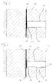
- the construction pit enclosure 10 has an annularly closed enclosure wall 12, of which only partially two slotted wall panels 14 according to FIG Fig. 1 are shown.
- the slot wall panels 14 have a substantially rectangular cross section. However, it may also be provided oval-shaped or circular cross-sections. Due to the process, the individual slot wall panels 14 are produced separately, with a vertical butt joint 16 forming between two adjacent slot wall panels 14.
- the vertical butt joint 16 extends from a bottom portion to the upper end of the respective adjacent slot wall panels 14.
- a joint tape 18 is placed in the creation of the slot wall panels 14, even before the Slot wall panels 14 are cured.
- the slot wall panels 14 are made in a conventional manner from a mortar or concrete and are optionally provided with a metal reinforcement.
- the construction pit enclosure 10 has a base plate 20.
- the bottom plate 20 is in the illustrated embodiment according to Fig. 2 also made of concrete and is connected via a projection 22 form-fitting manner with the enclosing wall 12.
- a horizontal butt joint 24 is formed, which forms in an annular manner along the enclosing wall 12 to the bottom plate 20.
- a receiving bore 15 is introduced before creating the bottom plate 22 in the enclosing wall 12 in the region of the vertical butt joint 16.
- a cylindrical sealing element 30 is inserted, through which the vertical butt joint 16 is sealed horizontally.
- Adjacent to the sealing element 30 is in the illustrated embodiment in the lower region of the bottom plate 20 along the horizontal butt joint 24, a horizontal seal 28, which is formed as an annular sealing band provided. The horizontal seal 28 prevents ingress of moisture or water along the annular horizontal butt joint 24 on the bottom plate 20.
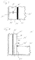
- a detail view of the seal according to the invention is shown, wherein in the receiving bore 15 in the slot wall panel 14, a sealing element 30 is inserted, which is designed as a hose sleeve 34.
- the hose sleeve 34 is completed on the one hand with a bottom.
- the receiving bore 15 is brought down to the joint tape 18.
- a sealing washer 36 may be provided from an elastic material. In principle, it is possible to introduce the sealing disc 36 before the creation of the receiving bore 15 with the joint tape 18 or in the created receiving bore 15.
- the hose sleeve 34 is provided with a fillable filling material, through which the flexible hose sleeve 34 is widened in its circumference and is pressed so tight against the wall of the receiving bore 15.
- FIG Fig. 4 An alternative embodiment of the sealing element 30 is shown in FIG Fig. 4 shown.
- the sealing element 30 is formed as a tubular metal sleeve 32 with a closed bottom portion. The bottom region adjoins the joint tape 18 in the slot wall panel 14 via a sealing washer 36.
- the metal sleeve 32 is inserted into the receiving bore 15 substantially by means of a press fit, wherein on the outer circumference a sealant, not shown, for sealing the gap between the wall of the receiving bore 15 and the metal sleeve 32 may be provided.
- the metal sleeve 32 is additionally anchored to the slot wall panel 14 at its end pointing to the inside of the enclosing wall 12 or to the interior of the excavation by means of an annular fastening element 33.
- the fastener 33 is formed as a flange-shaped retaining ring.
- the receiving bore 15 is initially introduced only to an intermediate portion 13 in the Umsch widelyungswand 12. Subsequently, a probing bore 19 with a small diameter, wherein the probing bore 19 is preferably carried out done by hand. Once the joint sealing tape 18 is reached, the probing hole 19 is terminated and the receiving bore 15 is performed up to the final depth according to the probing hole 19. Then, a sealing washer 36 for sealing any damage to the joint sealing strip 18 and then the sealing element 30, not shown, are used.
- FIG. 6 An alternative arrangement variant is in Fig. 6 shown.
- the receiving bore 15 is created by the joint sealing tape 18 through.
- the joint sealing strip 18 is pierced, so that the sealing element to be used takes over the function of the joint sealing strip 18 with.
- FIGS. 7 and 8 To illustrate the invention is in the FIGS. 7 and 8 a conventional excavation enclosure 10 'with a partially shown Umsch widelyungswand 12' of Schlitzwandpanelen 14 'and a bottom plate 20' shown.
- the vertical butt joints 16 'between adjacent Schlitzwandpanelen 14' are each sealed by a vertical joint sealing strip 18 ', so that no water from the bottom can penetrate into the pit laterally.
- a horizontal butt joint 24 'formed between the horizontal bottom plate 20' and the vertical enclosing wall 12 ' is sealed by means of a horizontal seal 28'.
- the enclosing wall 12 ' ends flush with the bottom plate 20'.
Landscapes
- Engineering & Computer Science (AREA)
- Mining & Mineral Resources (AREA)
- Structural Engineering (AREA)
- Life Sciences & Earth Sciences (AREA)
- General Life Sciences & Earth Sciences (AREA)
- Paleontology (AREA)
- Civil Engineering (AREA)
- General Engineering & Computer Science (AREA)
- Building Environments (AREA)
Priority Applications (2)
| Application Number | Priority Date | Filing Date | Title |
|---|---|---|---|
| EP16153356.7A EP3199708B1 (fr) | 2016-01-29 | 2016-01-29 | Enceinte de fouille et procédé de fabrication d'une enceinte de fouille |
| PCT/EP2016/081441 WO2017129319A1 (fr) | 2016-01-29 | 2016-12-16 | Enceinte pour trou de fondation et procédé servant à élaborer une enceinte pour trou de fondation |
Applications Claiming Priority (1)
| Application Number | Priority Date | Filing Date | Title |
|---|---|---|---|
| EP16153356.7A EP3199708B1 (fr) | 2016-01-29 | 2016-01-29 | Enceinte de fouille et procédé de fabrication d'une enceinte de fouille |
Publications (2)
| Publication Number | Publication Date |
|---|---|
| EP3199708A1 true EP3199708A1 (fr) | 2017-08-02 |
| EP3199708B1 EP3199708B1 (fr) | 2018-12-19 |
Family
ID=55274989
Family Applications (1)
| Application Number | Title | Priority Date | Filing Date |
|---|---|---|---|
| EP16153356.7A Not-in-force EP3199708B1 (fr) | 2016-01-29 | 2016-01-29 | Enceinte de fouille et procédé de fabrication d'une enceinte de fouille |
Country Status (2)
| Country | Link |
|---|---|
| EP (1) | EP3199708B1 (fr) |
| WO (1) | WO2017129319A1 (fr) |
Cited By (1)
| Publication number | Priority date | Publication date | Assignee | Title |
|---|---|---|---|---|
| CN111172990A (zh) * | 2019-11-11 | 2020-05-19 | 浙江省建筑设计研究院 | 预埋前后排钢筋套筒式预制地下连续墙竖向连接结构 |
Citations (6)
| Publication number | Priority date | Publication date | Assignee | Title |
|---|---|---|---|---|
| NL1008925C1 (nl) * | 1998-03-13 | 1999-09-14 | Alex Blokker Duik En Bergingsb | Werkwijze en inrichting voor het vervaardigen van een drukvloer uit beton. |
| US6164873A (en) | 1997-09-12 | 2000-12-26 | Finic B.V. | Double-wing deformable stop-end pipe for forming the joining surfaces of concrete-cast wall elements |
| DE10334730A1 (de) | 2003-07-30 | 2005-02-24 | Ed. Züblin Ag | Konstruktion einer wasserdichten Innenschale bei einem Bauwerk, welches in Deckelbauweise hergestellt wird und im Grundwasserhorizont einbindet |
| DE102005052162A1 (de) | 2004-11-12 | 2006-05-18 | Ed. Züblin Ag | Vorab wärmegedämmte Schlitzwand als Begrenzung eines temperaturhaltenden Speichers für Fluide und Herstellung solcher Speicher |
| EP2549021B1 (fr) | 2011-07-18 | 2013-09-11 | Bauer Spezialtiefbau GmbH | Centrale d'accumulation par pompage et son procédé de fabrication |
| EP2647765A1 (fr) | 2012-04-03 | 2013-10-09 | Bauer Spezialtiefbau GmbH | Elément de coffrage pour une paroi moulée et procédé de fabrication de cette paroi |
-
2016
- 2016-01-29 EP EP16153356.7A patent/EP3199708B1/fr not_active Not-in-force
- 2016-12-16 WO PCT/EP2016/081441 patent/WO2017129319A1/fr not_active Ceased
Patent Citations (6)
| Publication number | Priority date | Publication date | Assignee | Title |
|---|---|---|---|---|
| US6164873A (en) | 1997-09-12 | 2000-12-26 | Finic B.V. | Double-wing deformable stop-end pipe for forming the joining surfaces of concrete-cast wall elements |
| NL1008925C1 (nl) * | 1998-03-13 | 1999-09-14 | Alex Blokker Duik En Bergingsb | Werkwijze en inrichting voor het vervaardigen van een drukvloer uit beton. |
| DE10334730A1 (de) | 2003-07-30 | 2005-02-24 | Ed. Züblin Ag | Konstruktion einer wasserdichten Innenschale bei einem Bauwerk, welches in Deckelbauweise hergestellt wird und im Grundwasserhorizont einbindet |
| DE102005052162A1 (de) | 2004-11-12 | 2006-05-18 | Ed. Züblin Ag | Vorab wärmegedämmte Schlitzwand als Begrenzung eines temperaturhaltenden Speichers für Fluide und Herstellung solcher Speicher |
| EP2549021B1 (fr) | 2011-07-18 | 2013-09-11 | Bauer Spezialtiefbau GmbH | Centrale d'accumulation par pompage et son procédé de fabrication |
| EP2647765A1 (fr) | 2012-04-03 | 2013-10-09 | Bauer Spezialtiefbau GmbH | Elément de coffrage pour une paroi moulée et procédé de fabrication de cette paroi |
Cited By (2)
| Publication number | Priority date | Publication date | Assignee | Title |
|---|---|---|---|---|
| CN111172990A (zh) * | 2019-11-11 | 2020-05-19 | 浙江省建筑设计研究院 | 预埋前后排钢筋套筒式预制地下连续墙竖向连接结构 |
| CN111172990B (zh) * | 2019-11-11 | 2021-09-10 | 浙江省建筑设计研究院 | 预埋前后排钢筋套筒式预制地下连续墙竖向连接结构 |
Also Published As
| Publication number | Publication date |
|---|---|
| WO2017129319A1 (fr) | 2017-08-03 |
| EP3199708B1 (fr) | 2018-12-19 |
Similar Documents
| Publication | Publication Date | Title |
|---|---|---|
| DE1759338C3 (de) | Verfahren zum Herstellen eines Verpreßankers und Vorrichtung zur Durchführung des Verfahrens | |
| DE2651023C2 (de) | Verfahren zum Herstellen eines Ortbetonpfahles mit einer Fußerweiterung und Vorrichtung zum Durchführen des Verfahrens | |
| DE102007055878A1 (de) | Abdichtelement | |
| DE102008014700A1 (de) | Korrosionsgeschützter Selbstbohranker sowie Verfahren zu dessen Herstellung | |
| DE3445965A1 (de) | Verdichtende tiefgruendung, verfahren und vorrichtung zu deren herstellen | |
| DE3535320A1 (de) | Verfahren und vorrichtung zum setzen eines stab-, draht- oder rohrfoermigen einbauteils in eine bodenformation mit drueckendem wasser | |
| CH696445A5 (de) | Betonelement zum Verkleiden eines Tunnels. | |
| DE2226169C2 (de) | Vorrichtung zur Bildung eines Verpreßankers | |
| DE4422648C2 (de) | Sollriß-Fugenschiene | |
| DE102008018382A1 (de) | Verfahren zur Sicherung von Stützmauern | |
| CH600077A5 (en) | Seal for gaps in concrete structures | |
| EP3199708B1 (fr) | Enceinte de fouille et procédé de fabrication d'une enceinte de fouille | |
| DE2722978A1 (de) | Dichtung fuer spundbohlenschloesser | |
| DE2354764A1 (de) | Verfahren zur wasserdichten durchfuehrung eines durch eine bauwerks- oder eine baugrubenwand oder -sohle hindurch in das umgebende erdreich einzubringenden einbauteiles | |
| DE3322198C2 (fr) | ||
| DE3838880C1 (en) | Method of producing a grouted anchor, and grouted anchor for carrying out the method | |
| DE3634906A1 (de) | Betonfertigteil und verfahren zur herstellung einer schlitzwand unter verwendung des betonfertigteils | |
| DE4217711C2 (de) | Fugenband | |
| DE10104376C1 (de) | Verfahren zum Abdichten einer Bauwerksfuge und Fugenband dafür | |
| DE2617758C3 (de) | Verfahren zum Injizieren von Kunststoff-Füllungen in Wände, Mauern, Fassadenwände u.dgl. sowie Injektionsröhrchen zur Durchführung des Verfahrens | |
| DE3404074A1 (de) | Verfahren zum herstellen einer schlitzwand aus beton | |
| DE19522150C1 (de) | Verfahren zur Erstellung einer Baugrube mit einer Grundwasserabsperrung | |
| DE6609772U (de) | Bauteil zur herstellung von schlitz- oder bohrpfahlwaenden. | |
| EP1922449A1 (fr) | Procede et dispositif de consolidation de sols et de stabilisation de fondations | |
| DE102013008448B4 (de) | Verfahren und Vorrichtung zum nachträglichen Abdichten vom Erdreich umgebener Betonbauwerke mit Dichtungsfugen wie Tunneln |
Legal Events
| Date | Code | Title | Description |
|---|---|---|---|
| PUAI | Public reference made under article 153(3) epc to a published international application that has entered the european phase |
Free format text: ORIGINAL CODE: 0009012 |
|
| STAA | Information on the status of an ep patent application or granted ep patent |
Free format text: STATUS: THE APPLICATION HAS BEEN PUBLISHED |
|
| AK | Designated contracting states |
Kind code of ref document: A1 Designated state(s): AL AT BE BG CH CY CZ DE DK EE ES FI FR GB GR HR HU IE IS IT LI LT LU LV MC MK MT NL NO PL PT RO RS SE SI SK SM TR |
|
| AX | Request for extension of the european patent |
Extension state: BA ME |
|
| STAA | Information on the status of an ep patent application or granted ep patent |
Free format text: STATUS: REQUEST FOR EXAMINATION WAS MADE |
|
| 17P | Request for examination filed |
Effective date: 20180124 |
|
| RBV | Designated contracting states (corrected) |
Designated state(s): AL AT BE BG CH CY CZ DE DK EE ES FI FR GB GR HR HU IE IS IT LI LT LU LV MC MK MT NL NO PL PT RO RS SE SI SK SM TR |
|
| GRAP | Despatch of communication of intention to grant a patent |
Free format text: ORIGINAL CODE: EPIDOSNIGR1 |
|
| STAA | Information on the status of an ep patent application or granted ep patent |
Free format text: STATUS: GRANT OF PATENT IS INTENDED |
|
| INTG | Intention to grant announced |
Effective date: 20180622 |
|
| RIN1 | Information on inventor provided before grant (corrected) |
Inventor name: IDDA, KLAUS, DR. Inventor name: ACKERMANN, ANDREAS Inventor name: LORENZ, CHRISTIAN |
|
| GRAS | Grant fee paid |
Free format text: ORIGINAL CODE: EPIDOSNIGR3 |
|
| GRAJ | Information related to disapproval of communication of intention to grant by the applicant or resumption of examination proceedings by the epo deleted |
Free format text: ORIGINAL CODE: EPIDOSDIGR1 |
|
| GRAL | Information related to payment of fee for publishing/printing deleted |
Free format text: ORIGINAL CODE: EPIDOSDIGR3 |
|
| STAA | Information on the status of an ep patent application or granted ep patent |
Free format text: STATUS: REQUEST FOR EXAMINATION WAS MADE |
|
| GRAR | Information related to intention to grant a patent recorded |
Free format text: ORIGINAL CODE: EPIDOSNIGR71 |
|
| STAA | Information on the status of an ep patent application or granted ep patent |
Free format text: STATUS: GRANT OF PATENT IS INTENDED |
|
| INTC | Intention to grant announced (deleted) | ||
| GRAA | (expected) grant |
Free format text: ORIGINAL CODE: 0009210 |
|
| STAA | Information on the status of an ep patent application or granted ep patent |
Free format text: STATUS: THE PATENT HAS BEEN GRANTED |
|
| INTG | Intention to grant announced |
Effective date: 20181107 |
|
| AK | Designated contracting states |
Kind code of ref document: B1 Designated state(s): AL AT BE BG CH CY CZ DE DK EE ES FI FR GB GR HR HU IE IS IT LI LT LU LV MC MK MT NL NO PL PT RO RS SE SI SK SM TR |
|
| REG | Reference to a national code |
Ref country code: GB Ref legal event code: FG4D Free format text: NOT ENGLISH |
|
| REG | Reference to a national code |
Ref country code: CH Ref legal event code: EP |
|
| REG | Reference to a national code |
Ref country code: IE Ref legal event code: FG4D Free format text: LANGUAGE OF EP DOCUMENT: GERMAN |
|
| REG | Reference to a national code |
Ref country code: DE Ref legal event code: R096 Ref document number: 502016002872 Country of ref document: DE |
|
| REG | Reference to a national code |
Ref country code: AT Ref legal event code: REF Ref document number: 1078862 Country of ref document: AT Kind code of ref document: T Effective date: 20190115 |
|
| REG | Reference to a national code |
Ref country code: NL Ref legal event code: MP Effective date: 20181219 |
|
| PG25 | Lapsed in a contracting state [announced via postgrant information from national office to epo] |
Ref country code: LV Free format text: LAPSE BECAUSE OF FAILURE TO SUBMIT A TRANSLATION OF THE DESCRIPTION OR TO PAY THE FEE WITHIN THE PRESCRIBED TIME-LIMIT Effective date: 20181219 Ref country code: HR Free format text: LAPSE BECAUSE OF FAILURE TO SUBMIT A TRANSLATION OF THE DESCRIPTION OR TO PAY THE FEE WITHIN THE PRESCRIBED TIME-LIMIT Effective date: 20181219 Ref country code: LT Free format text: LAPSE BECAUSE OF FAILURE TO SUBMIT A TRANSLATION OF THE DESCRIPTION OR TO PAY THE FEE WITHIN THE PRESCRIBED TIME-LIMIT Effective date: 20181219 Ref country code: BG Free format text: LAPSE BECAUSE OF FAILURE TO SUBMIT A TRANSLATION OF THE DESCRIPTION OR TO PAY THE FEE WITHIN THE PRESCRIBED TIME-LIMIT Effective date: 20190319 Ref country code: FI Free format text: LAPSE BECAUSE OF FAILURE TO SUBMIT A TRANSLATION OF THE DESCRIPTION OR TO PAY THE FEE WITHIN THE PRESCRIBED TIME-LIMIT Effective date: 20181219 Ref country code: NO Free format text: LAPSE BECAUSE OF FAILURE TO SUBMIT A TRANSLATION OF THE DESCRIPTION OR TO PAY THE FEE WITHIN THE PRESCRIBED TIME-LIMIT Effective date: 20190319 |
|
| REG | Reference to a national code |
Ref country code: LT Ref legal event code: MG4D |
|
| PG25 | Lapsed in a contracting state [announced via postgrant information from national office to epo] |
Ref country code: RS Free format text: LAPSE BECAUSE OF FAILURE TO SUBMIT A TRANSLATION OF THE DESCRIPTION OR TO PAY THE FEE WITHIN THE PRESCRIBED TIME-LIMIT Effective date: 20181219 Ref country code: SE Free format text: LAPSE BECAUSE OF FAILURE TO SUBMIT A TRANSLATION OF THE DESCRIPTION OR TO PAY THE FEE WITHIN THE PRESCRIBED TIME-LIMIT Effective date: 20181219 Ref country code: GR Free format text: LAPSE BECAUSE OF FAILURE TO SUBMIT A TRANSLATION OF THE DESCRIPTION OR TO PAY THE FEE WITHIN THE PRESCRIBED TIME-LIMIT Effective date: 20190320 Ref country code: AL Free format text: LAPSE BECAUSE OF FAILURE TO SUBMIT A TRANSLATION OF THE DESCRIPTION OR TO PAY THE FEE WITHIN THE PRESCRIBED TIME-LIMIT Effective date: 20181219 |
|
| PG25 | Lapsed in a contracting state [announced via postgrant information from national office to epo] |
Ref country code: NL Free format text: LAPSE BECAUSE OF FAILURE TO SUBMIT A TRANSLATION OF THE DESCRIPTION OR TO PAY THE FEE WITHIN THE PRESCRIBED TIME-LIMIT Effective date: 20181219 |
|
| PG25 | Lapsed in a contracting state [announced via postgrant information from national office to epo] |
Ref country code: ES Free format text: LAPSE BECAUSE OF FAILURE TO SUBMIT A TRANSLATION OF THE DESCRIPTION OR TO PAY THE FEE WITHIN THE PRESCRIBED TIME-LIMIT Effective date: 20181219 Ref country code: PT Free format text: LAPSE BECAUSE OF FAILURE TO SUBMIT A TRANSLATION OF THE DESCRIPTION OR TO PAY THE FEE WITHIN THE PRESCRIBED TIME-LIMIT Effective date: 20190419 Ref country code: IT Free format text: LAPSE BECAUSE OF FAILURE TO SUBMIT A TRANSLATION OF THE DESCRIPTION OR TO PAY THE FEE WITHIN THE PRESCRIBED TIME-LIMIT Effective date: 20181219 Ref country code: CZ Free format text: LAPSE BECAUSE OF FAILURE TO SUBMIT A TRANSLATION OF THE DESCRIPTION OR TO PAY THE FEE WITHIN THE PRESCRIBED TIME-LIMIT Effective date: 20181219 Ref country code: PL Free format text: LAPSE BECAUSE OF FAILURE TO SUBMIT A TRANSLATION OF THE DESCRIPTION OR TO PAY THE FEE WITHIN THE PRESCRIBED TIME-LIMIT Effective date: 20181219 |
|
| PG25 | Lapsed in a contracting state [announced via postgrant information from national office to epo] |
Ref country code: RO Free format text: LAPSE BECAUSE OF FAILURE TO SUBMIT A TRANSLATION OF THE DESCRIPTION OR TO PAY THE FEE WITHIN THE PRESCRIBED TIME-LIMIT Effective date: 20181219 Ref country code: SK Free format text: LAPSE BECAUSE OF FAILURE TO SUBMIT A TRANSLATION OF THE DESCRIPTION OR TO PAY THE FEE WITHIN THE PRESCRIBED TIME-LIMIT Effective date: 20181219 Ref country code: IS Free format text: LAPSE BECAUSE OF FAILURE TO SUBMIT A TRANSLATION OF THE DESCRIPTION OR TO PAY THE FEE WITHIN THE PRESCRIBED TIME-LIMIT Effective date: 20190419 Ref country code: SM Free format text: LAPSE BECAUSE OF FAILURE TO SUBMIT A TRANSLATION OF THE DESCRIPTION OR TO PAY THE FEE WITHIN THE PRESCRIBED TIME-LIMIT Effective date: 20181219 Ref country code: EE Free format text: LAPSE BECAUSE OF FAILURE TO SUBMIT A TRANSLATION OF THE DESCRIPTION OR TO PAY THE FEE WITHIN THE PRESCRIBED TIME-LIMIT Effective date: 20181219 |
|
| REG | Reference to a national code |
Ref country code: CH Ref legal event code: PL |
|
| REG | Reference to a national code |
Ref country code: DE Ref legal event code: R097 Ref document number: 502016002872 Country of ref document: DE |
|
| PG25 | Lapsed in a contracting state [announced via postgrant information from national office to epo] |
Ref country code: LU Free format text: LAPSE BECAUSE OF NON-PAYMENT OF DUE FEES Effective date: 20190129 |
|
| REG | Reference to a national code |
Ref country code: BE Ref legal event code: MM Effective date: 20190131 |
|
| PLBE | No opposition filed within time limit |
Free format text: ORIGINAL CODE: 0009261 |
|
| STAA | Information on the status of an ep patent application or granted ep patent |
Free format text: STATUS: NO OPPOSITION FILED WITHIN TIME LIMIT |
|
| REG | Reference to a national code |
Ref country code: IE Ref legal event code: MM4A |
|
| PG25 | Lapsed in a contracting state [announced via postgrant information from national office to epo] |
Ref country code: DK Free format text: LAPSE BECAUSE OF FAILURE TO SUBMIT A TRANSLATION OF THE DESCRIPTION OR TO PAY THE FEE WITHIN THE PRESCRIBED TIME-LIMIT Effective date: 20181219 Ref country code: MC Free format text: LAPSE BECAUSE OF FAILURE TO SUBMIT A TRANSLATION OF THE DESCRIPTION OR TO PAY THE FEE WITHIN THE PRESCRIBED TIME-LIMIT Effective date: 20181219 |
|
| 26N | No opposition filed |
Effective date: 20190920 |
|
| PG25 | Lapsed in a contracting state [announced via postgrant information from national office to epo] |
Ref country code: BE Free format text: LAPSE BECAUSE OF NON-PAYMENT OF DUE FEES Effective date: 20190131 |
|
| PG25 | Lapsed in a contracting state [announced via postgrant information from national office to epo] |
Ref country code: CH Free format text: LAPSE BECAUSE OF NON-PAYMENT OF DUE FEES Effective date: 20190131 Ref country code: LI Free format text: LAPSE BECAUSE OF NON-PAYMENT OF DUE FEES Effective date: 20190131 |
|
| PG25 | Lapsed in a contracting state [announced via postgrant information from national office to epo] |
Ref country code: IE Free format text: LAPSE BECAUSE OF NON-PAYMENT OF DUE FEES Effective date: 20190129 |
|
| PG25 | Lapsed in a contracting state [announced via postgrant information from national office to epo] |
Ref country code: SI Free format text: LAPSE BECAUSE OF FAILURE TO SUBMIT A TRANSLATION OF THE DESCRIPTION OR TO PAY THE FEE WITHIN THE PRESCRIBED TIME-LIMIT Effective date: 20181219 Ref country code: FR Free format text: LAPSE BECAUSE OF NON-PAYMENT OF DUE FEES Effective date: 20190219 |
|
| PG25 | Lapsed in a contracting state [announced via postgrant information from national office to epo] |
Ref country code: TR Free format text: LAPSE BECAUSE OF FAILURE TO SUBMIT A TRANSLATION OF THE DESCRIPTION OR TO PAY THE FEE WITHIN THE PRESCRIBED TIME-LIMIT Effective date: 20181219 |
|
| PG25 | Lapsed in a contracting state [announced via postgrant information from national office to epo] |
Ref country code: MT Free format text: LAPSE BECAUSE OF FAILURE TO SUBMIT A TRANSLATION OF THE DESCRIPTION OR TO PAY THE FEE WITHIN THE PRESCRIBED TIME-LIMIT Effective date: 20181219 |
|
| GBPC | Gb: european patent ceased through non-payment of renewal fee |
Effective date: 20200129 |
|
| PG25 | Lapsed in a contracting state [announced via postgrant information from national office to epo] |
Ref country code: GB Free format text: LAPSE BECAUSE OF NON-PAYMENT OF DUE FEES Effective date: 20200129 |
|
| PG25 | Lapsed in a contracting state [announced via postgrant information from national office to epo] |
Ref country code: CY Free format text: LAPSE BECAUSE OF FAILURE TO SUBMIT A TRANSLATION OF THE DESCRIPTION OR TO PAY THE FEE WITHIN THE PRESCRIBED TIME-LIMIT Effective date: 20181219 |
|
| PG25 | Lapsed in a contracting state [announced via postgrant information from national office to epo] |
Ref country code: HU Free format text: LAPSE BECAUSE OF FAILURE TO SUBMIT A TRANSLATION OF THE DESCRIPTION OR TO PAY THE FEE WITHIN THE PRESCRIBED TIME-LIMIT; INVALID AB INITIO Effective date: 20160129 |
|
| REG | Reference to a national code |
Ref country code: AT Ref legal event code: MM01 Ref document number: 1078862 Country of ref document: AT Kind code of ref document: T Effective date: 20210129 |
|
| PG25 | Lapsed in a contracting state [announced via postgrant information from national office to epo] |
Ref country code: AT Free format text: LAPSE BECAUSE OF NON-PAYMENT OF DUE FEES Effective date: 20210129 |
|
| PG25 | Lapsed in a contracting state [announced via postgrant information from national office to epo] |
Ref country code: MK Free format text: LAPSE BECAUSE OF FAILURE TO SUBMIT A TRANSLATION OF THE DESCRIPTION OR TO PAY THE FEE WITHIN THE PRESCRIBED TIME-LIMIT Effective date: 20181219 |
|
| PGFP | Annual fee paid to national office [announced via postgrant information from national office to epo] |
Ref country code: DE Payment date: 20230120 Year of fee payment: 8 |
|
| REG | Reference to a national code |
Ref country code: DE Ref legal event code: R119 Ref document number: 502016002872 Country of ref document: DE |
|
| PG25 | Lapsed in a contracting state [announced via postgrant information from national office to epo] |
Ref country code: DE Free format text: LAPSE BECAUSE OF NON-PAYMENT OF DUE FEES Effective date: 20240801 |
|
| PG25 | Lapsed in a contracting state [announced via postgrant information from national office to epo] |
Ref country code: DE Free format text: LAPSE BECAUSE OF NON-PAYMENT OF DUE FEES Effective date: 20240801 |