EP3199733A1 - Dispositif destiné à verrouiller des ouvertures d'immeubles - Google Patents
Dispositif destiné à verrouiller des ouvertures d'immeubles Download PDFInfo
- Publication number
- EP3199733A1 EP3199733A1 EP16020458.2A EP16020458A EP3199733A1 EP 3199733 A1 EP3199733 A1 EP 3199733A1 EP 16020458 A EP16020458 A EP 16020458A EP 3199733 A1 EP3199733 A1 EP 3199733A1
- Authority
- EP
- European Patent Office
- Prior art keywords
- roller
- roller carrier
- driver
- plug
- pin
- Prior art date
- Legal status (The legal status is an assumption and is not a legal conclusion. Google has not performed a legal analysis and makes no representation as to the accuracy of the status listed.)
- Granted
Links
Images
Classifications
-
- E—FIXED CONSTRUCTIONS
- E05—LOCKS; KEYS; WINDOW OR DOOR FITTINGS; SAFES
- E05D—HINGES OR SUSPENSION DEVICES FOR DOORS, WINDOWS OR WINGS
- E05D15/00—Suspension arrangements for wings
- E05D15/06—Suspension arrangements for wings for wings sliding horizontally more or less in their own plane
- E05D15/08—Suspension arrangements for wings for wings sliding horizontally more or less in their own plane consisting of two or more independent parts movable each in its own guides
-
- E—FIXED CONSTRUCTIONS
- E05—LOCKS; KEYS; WINDOW OR DOOR FITTINGS; SAFES
- E05D—HINGES OR SUSPENSION DEVICES FOR DOORS, WINDOWS OR WINGS
- E05D15/00—Suspension arrangements for wings
- E05D15/06—Suspension arrangements for wings for wings sliding horizontally more or less in their own plane
- E05D15/0621—Details, e.g. suspension or supporting guides
- E05D15/066—Details, e.g. suspension or supporting guides for wings supported at the bottom
- E05D15/0665—Details, e.g. suspension or supporting guides for wings supported at the bottom on wheels with fixed axis
-
- E—FIXED CONSTRUCTIONS
- E05—LOCKS; KEYS; WINDOW OR DOOR FITTINGS; SAFES
- E05F—DEVICES FOR MOVING WINGS INTO OPEN OR CLOSED POSITION; CHECKS FOR WINGS; WING FITTINGS NOT OTHERWISE PROVIDED FOR, CONCERNED WITH THE FUNCTIONING OF THE WING
- E05F17/00—Special devices for shifting a plurality of wings operated simultaneously
- E05F17/002—Special devices for shifting a plurality of wings operated simultaneously for wings which lie one behind the other when closed
-
- E—FIXED CONSTRUCTIONS
- E05—LOCKS; KEYS; WINDOW OR DOOR FITTINGS; SAFES
- E05F—DEVICES FOR MOVING WINGS INTO OPEN OR CLOSED POSITION; CHECKS FOR WINGS; WING FITTINGS NOT OTHERWISE PROVIDED FOR, CONCERNED WITH THE FUNCTIONING OF THE WING
- E05F17/00—Special devices for shifting a plurality of wings operated simultaneously
- E05F2017/005—Special devices for shifting a plurality of wings operated simultaneously for sliding wings
- E05F2017/007—Special devices for shifting a plurality of wings operated simultaneously for sliding wings with means for interlocking the wings
-
- E—FIXED CONSTRUCTIONS
- E05—LOCKS; KEYS; WINDOW OR DOOR FITTINGS; SAFES
- E05Y—INDEXING SCHEME ASSOCIATED WITH SUBCLASSES E05D AND E05F, RELATING TO CONSTRUCTION ELEMENTS, ELECTRIC CONTROL, POWER SUPPLY, POWER SIGNAL OR TRANSMISSION, USER INTERFACES, MOUNTING OR COUPLING, DETAILS, ACCESSORIES, AUXILIARY OPERATIONS NOT OTHERWISE PROVIDED FOR, APPLICATION THEREOF
- E05Y2201/00—Constructional elements; Accessories therefor
- E05Y2201/60—Suspension or transmission members; Accessories therefor
- E05Y2201/622—Suspension or transmission members elements
- E05Y2201/64—Carriers
-
- E—FIXED CONSTRUCTIONS
- E05—LOCKS; KEYS; WINDOW OR DOOR FITTINGS; SAFES
- E05Y—INDEXING SCHEME ASSOCIATED WITH SUBCLASSES E05D AND E05F, RELATING TO CONSTRUCTION ELEMENTS, ELECTRIC CONTROL, POWER SUPPLY, POWER SIGNAL OR TRANSMISSION, USER INTERFACES, MOUNTING OR COUPLING, DETAILS, ACCESSORIES, AUXILIARY OPERATIONS NOT OTHERWISE PROVIDED FOR, APPLICATION THEREOF
- E05Y2800/00—Details, accessories and auxiliary operations not otherwise provided for
- E05Y2800/15—Applicability
- E05Y2800/17—Universally applicable
- E05Y2800/172—Universally applicable on different wing or frame locations
-
- E—FIXED CONSTRUCTIONS
- E05—LOCKS; KEYS; WINDOW OR DOOR FITTINGS; SAFES
- E05Y—INDEXING SCHEME ASSOCIATED WITH SUBCLASSES E05D AND E05F, RELATING TO CONSTRUCTION ELEMENTS, ELECTRIC CONTROL, POWER SUPPLY, POWER SIGNAL OR TRANSMISSION, USER INTERFACES, MOUNTING OR COUPLING, DETAILS, ACCESSORIES, AUXILIARY OPERATIONS NOT OTHERWISE PROVIDED FOR, APPLICATION THEREOF
- E05Y2800/00—Details, accessories and auxiliary operations not otherwise provided for
- E05Y2800/15—Applicability
- E05Y2800/17—Universally applicable
- E05Y2800/172—Universally applicable on different wing or frame locations
- E05Y2800/174—Universally applicable on different wing or frame locations on the left or right side
Definitions
- the invention relates to a device for closing building openings, in particular a sliding door or a sliding window, with a plurality of each guided on a running rail carriage sliding leaves, which are provided in the region of their respective adjacent sliding wing ends facing with drivers for mutual entrainment at least in the closing direction, wherein the carriage rail side with the wing ends associated, a driver-containing roller carriers is provided for each of a roller.
- the carriers are formed integrally with the roller carriers or inseparably connected thereto. Since drivers projecting to the right and to the left are required, different types of roller carriers have emerged to date with carriers projecting to the right or left. This increases the cost of manufacturing and warehousing and requires great attention during assembly. In addition, a subsequent change of the closing direction of the sliding door or the sliding window requires a complex replacement of the complete roll carrier. The known arrangements are therefore not easy and easy to install and not economical enough overall.
- the driver as is formed by the associated roller carrier separate part, which is designed symmetrically to its median transverse plane and attachable by means of a symmetrical to the central longitudinal plane of the roller carrier holding device on the associated roller carrier.
- the roller carrier each having a symmetrical to its central longitudinal plane cross-section, vertical Einsteckaus predominantlyung and the driver have a symmetrical to said central longitudinal plane foot with a fitting into the Einsteckaus predominantlyung, plug-in and a laterally projecting laterally projecting stop member.
- roller carrier with a Einsteckausnaturalung containing, the roller upstream Bag is provided. This facilitates a secure attachment of engaging with its plug-in pin in the Einsteckausnaturalung driver.
- the engaging in the associated Einsteckausnaturalung plug-in pin of the driver with the EinsteckausEnglishung containing pocket of the roll carrier be pinned.
- the pocket and the plug are expediently provided with a transverse pin associated with a transverse bore whose axis extends in the median transverse plane of the driver, so that the desired rotational offset is ensured by 180 °.
- the start-up member of the driver may be provided at its front end in the start-up direction with a buffer preferably made of rubber or rubber-like material, which is expediently designed as an attachable member to the start-up member and this has a plug-in, a continuous in the start-up direction Plug-in channel of the start-up member is assigned. In this way it is ensured that the buffer can be connected to the start-up element either from each end.
- the side walls of the continuous insertion channel of the start-up member may be provided with preferably formed as a transverse bore recesses whose axis also extends in the driver side central transverse plane and can engage in the lateral locking knobs of the buffer-side spigot, the axis of which also extends in the catch central transverse plane.
- Field of the invention are sliding sash systems such as sliding doors, sliding windows or the like.
- the basic structure of such arrangements is known. The following description therefore essentially relates only to the improvement according to the invention.
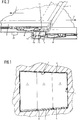
- the the Fig. 1 underlying, built into a building opening 1 sliding door contains several, here three wings 2, 3, 4, with at least their thickness corresponding offset on juxtaposed track strips a bottom side provided running rail 5 in Fig. 6 indicated type are included.
- a guide rail 6 acting as a safety catch is provided in the area of the upper edge of the building opening 1.
- the wings 2, 3, 4 are usually made of a plate-shaped element, such as a glass plate, with its lower edge in an associated Version of a lower carriage 7, which is provided with running on the associated track bar of the running rail 5 rollers 8.
- a plate-shaped element such as a glass plate
- the wings 2, 3, 4 arranged over the width of the building opening 1 one behind the other.
- the said wings are pushed to the side that they are largely covering one behind the other.
- the rear in the closing direction of the wing 2 is usually secured by means of a releasable only in special cases lock against displacement.
- the further wings 3, 4 are displaceable in both directions for closing and opening.
- the front in the closing direction of the wing 4 is provided for this purpose with a provided in the region of its front edge handle 9 and can be locked by means of a conveniently integrated into the handle 9 lock in the closed position.
- the handle 9 allows a direct contact and thus direct initiation of a displacement force in the wing 4.
- the adjacent wing 3 is taken on actuation of the wing 4 of this. If further displaceable wings are provided, these are also entrained by the respective upstream in the closing direction wings.
- the sliding wings like out Fig. 2 can be seen, in the region of their respective adjacent sliding sash facing ends provided with at least during a movement in the closing direction in mutual engagement carriers 10.
- the closing direction is in Fig. 2 indicated by the arrow s, the opening direction by the arrow ö.
- the drivers 10 are located in the region of the wing end between a roller 8 and the adjacent side wing end face 11.
- the driver 10 adjacent wings have opposite the rempligelstoffstoffsebene oppositely projecting laterally starting members 12 which can start with their facing end faces together, where they engage behind so that an attachment of the successive wings in a sliding direction, here in the closing direction s, takes place.
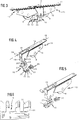
- the carriage 7 of the wings contains, as out Fig. 3 it can be seen, its rollers 8 associated roller carrier 13, which also carry the respective associated roller 8 adjacent carrier 10.
- the roller carriers 13 are fixable with an upper support rail 14 on the carriage 7 underlying rail and have a bearing thereon bearing block 15 for the associated roller 8, and a next arranged pocket 16, which is a socket for receiving the formed as a separate component, associated Driver 10 forms.
- the driver 10 forming, separate component is how the 4 and 5 let recognize, designed symmetrically to its median transverse plane 17 and fixed by means of a direction indicated by a section line 18 central longitudinal plane of the roller carrier 13 symmetrically designed holding device on the roller carrier 13.
- roller carrier side pocket 16 having a symmetrical to the central longitudinal plane 18 cross-section, vertical Einsteckausnaturalung 19 and the driver 10 with a symmetrical to its median transverse plane 17 foot with a fitting into the Einsteckausnaturalung 19 pluggable, vertical Spigot 20 provided which goes up from a base plate 21 from which the start-up member 12 forming projection goes down.
- the base plate 21 is larger than the cross section of the spigot 20, so that there is a circumferential collar that starts when inserting the plug pin 20 into the Einsteckaus fundamentalung 19 to the lower end face of the pocket 16 and thus results in a limitation of the insertion depth.
- the plug-in pin 20 is provided with a transverse bore 22, whose axis extends in its central transverse plane 17 and which is aligned with inserted into the EinsteckausEnglishung 19 spigot 20 with a correspondingly arranged transverse bore 23 of the Einsteckausnaturalung 19 containing pocket 16.
- This allows a mutual pinning of the interlocking elements by means of an associated transverse pin 24, which may also be a screwable into the mutually aligned transverse bores screw etc., which simplifies a subsequent solution of the compound.
- the outgoing from the base plate 21 downwards, opposite the plug-in pin 20 laterally projecting stopper 12 is, as from the Fig. 2 and 3 is removable, provided at its upstream end with a buffer 25, which may preferably be made of rubber or rubber-like material, resulting in a shock absorption and noise reduction.
- the buffer 25 is, as shown in FIGS 4 and 5 can be seen as formed on the associated start-up member 12 attachable component.
- the projection 12 forming the projection is provided with a continuous insertion in the direction of insertion 26.
- the buffer 25 has an outgoing from a front stop plate plug-in pin 27 which is inserted into the insertion channel 26. This passes through the entire width of the start-up member 12, so that the buffer 25 can be selectively infected from each side and accordingly the buffer 25 can be attached regardless of the desired Auskragcardi the start-up member 12 in any case on the right side.
- the buffer 25 can be conveniently determined by a latching connection.
- the plug-in pin 27 is divided into two spaced-apart legs, which are provided with laterally projecting locking nubs 29 whose axis in the mounting position also in the median transverse plane 17 and which can accordingly engage in the transverse bore 28, wherein the two legs of the spigot 27 initially counter their inherent elasticity are pressed together and then spring back as soon as the locking knobs 29 come into alignment with the transverse bore 28.
- the Miit staff 10 are, as already mentioned above, active in an actuation of the wings in the closing direction s.
- the projection 10 may be a rubber buffer, etc., which also serves for shock absorption and noise reduction.
- the running rail 5 includes, as already mentioned above, several, the successively arranged wings 2, 3, 4 associated track strips 31. These can, as Fig. 6 shows, be formed as a strip-shaped webs on which the trained on the type of pulleys rollers 8 are supported and guided.
- the start-up members 12 of the drivers 10 are, as best of Fig. 3 can be seen, positioned deeper than the outer diameter of the rollers 8 and are therefore surmounted by the track strips 31.
- the lateral projection of the start-up members 12 relative to the central longitudinal plane 18 of the roller carrier or wing may therefore correspond to at most half the thickness of the webs 31 forming webs plus the clear distance adjacent track rails 31 to avoid collisions.
- the web strips 31 acting as track strips are expediently provided with their upper region encompassing, approximately U-shaped cover profiles 32 in cross-section.
Landscapes
- Engineering & Computer Science (AREA)
- Mechanical Engineering (AREA)
- Support Devices For Sliding Doors (AREA)
- Power-Operated Mechanisms For Wings (AREA)
Applications Claiming Priority (1)
| Application Number | Priority Date | Filing Date | Title |
|---|---|---|---|
| DE202016000481.7U DE202016000481U1 (de) | 2016-01-27 | 2016-01-27 | Vorrichtung zum Verschließen von Gebäudeöffnungen |
Publications (3)
| Publication Number | Publication Date |
|---|---|
| EP3199733A1 true EP3199733A1 (fr) | 2017-08-02 |
| EP3199733C0 EP3199733C0 (fr) | 2024-08-07 |
| EP3199733B1 EP3199733B1 (fr) | 2024-08-07 |
Family
ID=55445209
Family Applications (1)
| Application Number | Title | Priority Date | Filing Date |
|---|---|---|---|
| EP16020458.2A Active EP3199733B1 (fr) | 2016-01-27 | 2016-11-23 | Dispositif destiné à verrouiller des ouvertures d'immeubles |
Country Status (2)
| Country | Link |
|---|---|
| EP (1) | EP3199733B1 (fr) |
| DE (1) | DE202016000481U1 (fr) |
Families Citing this family (1)
| Publication number | Priority date | Publication date | Assignee | Title |
|---|---|---|---|---|
| JP6722892B2 (ja) * | 2016-07-25 | 2020-07-15 | パナソニックIpマネジメント株式会社 | 引戸装置 |
Citations (4)
| Publication number | Priority date | Publication date | Assignee | Title |
|---|---|---|---|---|
| GB2134167A (en) * | 1983-01-21 | 1984-08-08 | Guenter & Co Oni Metall | Shower cubicle sealing door |
| EP2213820A2 (fr) * | 2009-02-02 | 2010-08-04 | Casali A.V. s.r.l. | Kit pour monter deux battants coulissants fabriqués en verre ou autre matériau dans un système de porte escamotable |
| EP2476840A1 (fr) * | 2011-01-13 | 2012-07-18 | Sunflex Aluminiumsysteme GmbH | Dispositif de galets de roulement |
| DE102013109710A1 (de) * | 2013-09-05 | 2015-03-05 | Hettich-Heinze Gmbh & Co. Kg | Beschlag für eine Schiebetür |
Family Cites Families (1)
| Publication number | Priority date | Publication date | Assignee | Title |
|---|---|---|---|---|
| JP3787267B2 (ja) * | 2000-09-05 | 2006-06-21 | 株式会社ムラコシ精工 | 上吊式扉支持装置 |
-
2016
- 2016-01-27 DE DE202016000481.7U patent/DE202016000481U1/de not_active Expired - Lifetime
- 2016-11-23 EP EP16020458.2A patent/EP3199733B1/fr active Active
Patent Citations (4)
| Publication number | Priority date | Publication date | Assignee | Title |
|---|---|---|---|---|
| GB2134167A (en) * | 1983-01-21 | 1984-08-08 | Guenter & Co Oni Metall | Shower cubicle sealing door |
| EP2213820A2 (fr) * | 2009-02-02 | 2010-08-04 | Casali A.V. s.r.l. | Kit pour monter deux battants coulissants fabriqués en verre ou autre matériau dans un système de porte escamotable |
| EP2476840A1 (fr) * | 2011-01-13 | 2012-07-18 | Sunflex Aluminiumsysteme GmbH | Dispositif de galets de roulement |
| DE102013109710A1 (de) * | 2013-09-05 | 2015-03-05 | Hettich-Heinze Gmbh & Co. Kg | Beschlag für eine Schiebetür |
Also Published As
| Publication number | Publication date |
|---|---|
| DE202016000481U1 (de) | 2016-02-11 |
| EP3199733C0 (fr) | 2024-08-07 |
| EP3199733B1 (fr) | 2024-08-07 |
Similar Documents
| Publication | Publication Date | Title |
|---|---|---|
| DE19846308A1 (de) | Beschlag für Fenster oder Türen | |
| DE102011011113B4 (de) | Rahmensystem eines Partikelschutzgitters | |
| DE4420646C2 (de) | Führungsanordnung für Schiebetüren, insbesondere Aufzugstüren | |
| DE3033751C2 (de) | Beschlag für den Schiebeflügel von Fenstern, Türen oder dgl. aus Holz- oder Kunststoffprofilen | |
| EP3045638A1 (fr) | Système de battant coulissant et rotatif | |
| AT507493B1 (de) | Laufrolle für einen schiebeflügel | |
| EP3199733B1 (fr) | Dispositif destiné à verrouiller des ouvertures d'immeubles | |
| EP2078812A2 (fr) | Elément de recouvrement pour un rail de guidage | |
| WO2018046285A1 (fr) | Dispositif anti-soulèvement pour un battant déplaçable et pouvant être soulevé pour être déplacé | |
| DE102006005610B4 (de) | Insektenschutzrahmen | |
| EP3715578A1 (fr) | Porte de protection contre les insectes | |
| DE102016117336B3 (de) | Lagerungs-Vorrichtung eines elastisch gelagerten Torflügels | |
| DE102023117279A1 (de) | Schiebetüranordnung | |
| DE2158948C3 (de) | Eckbeschlag für Fenster und Türen od. dgl., insbesondere Eckumlenkung für Treibstangenbeschläge | |
| CH706604A2 (de) | Objektband und Anordnung eines Objektbands an einem Tür- oder Fensterblatt und einer Tür- oder Fensterzarge. | |
| EP1498563B1 (fr) | Dispositif pour créer une fente d'aération | |
| AT517263A1 (de) | Schließvorrichtung für eine Schiebetür | |
| DE102009005177A1 (de) | Verschiebliches Tür- oder Fensterelement | |
| EP3301249B1 (fr) | Dispositif d'étanchéité doté d'une barre d'étanchéité mobile | |
| DE2443619A1 (de) | Verschlussgestaenge fuer fenster, tueren oder dgl | |
| EP3085281B1 (fr) | Élement coulissant destine a ranger par coulissement un rideau ou une bache | |
| DE1708173C3 (de) | Scheibenführung für ein in den Fensterschacht eines Fahrzeuges versenkbares Schiebefenster | |
| EP1916373A2 (fr) | Paroi intermédiaire de bâtiment dotée d'une porte coulissante en verre | |
| EP3081732A1 (fr) | Dispositif d'entraînement | |
| EP3925916B1 (fr) | Porte d'ascenseur doté d'un guidage de battant de porte |
Legal Events
| Date | Code | Title | Description |
|---|---|---|---|
| PUAI | Public reference made under article 153(3) epc to a published international application that has entered the european phase |
Free format text: ORIGINAL CODE: 0009012 |
|
| STAA | Information on the status of an ep patent application or granted ep patent |
Free format text: STATUS: THE APPLICATION HAS BEEN PUBLISHED |
|
| AK | Designated contracting states |
Kind code of ref document: A1 Designated state(s): AL AT BE BG CH CY CZ DE DK EE ES FI FR GB GR HR HU IE IS IT LI LT LU LV MC MK MT NL NO PL PT RO RS SE SI SK SM TR |
|
| AX | Request for extension of the european patent |
Extension state: BA ME |
|
| STAA | Information on the status of an ep patent application or granted ep patent |
Free format text: STATUS: REQUEST FOR EXAMINATION WAS MADE |
|
| 17P | Request for examination filed |
Effective date: 20180202 |
|
| RBV | Designated contracting states (corrected) |
Designated state(s): AL AT BE BG CH CY CZ DE DK EE ES FI FR GB GR HR HU IE IS IT LI LT LU LV MC MK MT NL NO PL PT RO RS SE SI SK SM TR |
|
| STAA | Information on the status of an ep patent application or granted ep patent |
Free format text: STATUS: EXAMINATION IS IN PROGRESS |
|
| 17Q | First examination report despatched |
Effective date: 20191218 |
|
| GRAP | Despatch of communication of intention to grant a patent |
Free format text: ORIGINAL CODE: EPIDOSNIGR1 |
|
| STAA | Information on the status of an ep patent application or granted ep patent |
Free format text: STATUS: GRANT OF PATENT IS INTENDED |
|
| INTG | Intention to grant announced |
Effective date: 20240408 |
|
| GRAS | Grant fee paid |
Free format text: ORIGINAL CODE: EPIDOSNIGR3 |
|
| GRAA | (expected) grant |
Free format text: ORIGINAL CODE: 0009210 |
|
| STAA | Information on the status of an ep patent application or granted ep patent |
Free format text: STATUS: THE PATENT HAS BEEN GRANTED |
|
| AK | Designated contracting states |
Kind code of ref document: B1 Designated state(s): AL AT BE BG CH CY CZ DE DK EE ES FI FR GB GR HR HU IE IS IT LI LT LU LV MC MK MT NL NO PL PT RO RS SE SI SK SM TR |
|
| REG | Reference to a national code |
Ref country code: GB Ref legal event code: FG4D Free format text: NOT ENGLISH |
|
| REG | Reference to a national code |
Ref country code: CH Ref legal event code: EP |
|
| REG | Reference to a national code |
Ref country code: IE Ref legal event code: FG4D Free format text: LANGUAGE OF EP DOCUMENT: GERMAN |
|
| REG | Reference to a national code |
Ref country code: DE Ref legal event code: R096 Ref document number: 502016016658 Country of ref document: DE |
|
| U01 | Request for unitary effect filed |
Effective date: 20240827 |
|
| U07 | Unitary effect registered |
Designated state(s): AT BE BG DE DK EE FI FR IT LT LU LV MT NL PT RO SE SI Effective date: 20240905 |
|
| PG25 | Lapsed in a contracting state [announced via postgrant information from national office to epo] |
Ref country code: NO Free format text: LAPSE BECAUSE OF FAILURE TO SUBMIT A TRANSLATION OF THE DESCRIPTION OR TO PAY THE FEE WITHIN THE PRESCRIBED TIME-LIMIT Effective date: 20241107 |
|
| U20 | Renewal fee for the european patent with unitary effect paid |
Year of fee payment: 9 Effective date: 20241205 |
|
| PG25 | Lapsed in a contracting state [announced via postgrant information from national office to epo] |
Ref country code: GR Free format text: LAPSE BECAUSE OF FAILURE TO SUBMIT A TRANSLATION OF THE DESCRIPTION OR TO PAY THE FEE WITHIN THE PRESCRIBED TIME-LIMIT Effective date: 20241108 Ref country code: PL Free format text: LAPSE BECAUSE OF FAILURE TO SUBMIT A TRANSLATION OF THE DESCRIPTION OR TO PAY THE FEE WITHIN THE PRESCRIBED TIME-LIMIT Effective date: 20240807 |
|
| PG25 | Lapsed in a contracting state [announced via postgrant information from national office to epo] |
Ref country code: IS Free format text: LAPSE BECAUSE OF FAILURE TO SUBMIT A TRANSLATION OF THE DESCRIPTION OR TO PAY THE FEE WITHIN THE PRESCRIBED TIME-LIMIT Effective date: 20241207 |
|
| PG25 | Lapsed in a contracting state [announced via postgrant information from national office to epo] |
Ref country code: HR Free format text: LAPSE BECAUSE OF FAILURE TO SUBMIT A TRANSLATION OF THE DESCRIPTION OR TO PAY THE FEE WITHIN THE PRESCRIBED TIME-LIMIT Effective date: 20240807 |
|
| PG25 | Lapsed in a contracting state [announced via postgrant information from national office to epo] |
Ref country code: RS Free format text: LAPSE BECAUSE OF FAILURE TO SUBMIT A TRANSLATION OF THE DESCRIPTION OR TO PAY THE FEE WITHIN THE PRESCRIBED TIME-LIMIT Effective date: 20241107 Ref country code: ES Free format text: LAPSE BECAUSE OF FAILURE TO SUBMIT A TRANSLATION OF THE DESCRIPTION OR TO PAY THE FEE WITHIN THE PRESCRIBED TIME-LIMIT Effective date: 20240807 |
|
| PG25 | Lapsed in a contracting state [announced via postgrant information from national office to epo] |
Ref country code: RS Free format text: LAPSE BECAUSE OF FAILURE TO SUBMIT A TRANSLATION OF THE DESCRIPTION OR TO PAY THE FEE WITHIN THE PRESCRIBED TIME-LIMIT Effective date: 20241107 Ref country code: PL Free format text: LAPSE BECAUSE OF FAILURE TO SUBMIT A TRANSLATION OF THE DESCRIPTION OR TO PAY THE FEE WITHIN THE PRESCRIBED TIME-LIMIT Effective date: 20240807 Ref country code: NO Free format text: LAPSE BECAUSE OF FAILURE TO SUBMIT A TRANSLATION OF THE DESCRIPTION OR TO PAY THE FEE WITHIN THE PRESCRIBED TIME-LIMIT Effective date: 20241107 Ref country code: IS Free format text: LAPSE BECAUSE OF FAILURE TO SUBMIT A TRANSLATION OF THE DESCRIPTION OR TO PAY THE FEE WITHIN THE PRESCRIBED TIME-LIMIT Effective date: 20241207 Ref country code: HR Free format text: LAPSE BECAUSE OF FAILURE TO SUBMIT A TRANSLATION OF THE DESCRIPTION OR TO PAY THE FEE WITHIN THE PRESCRIBED TIME-LIMIT Effective date: 20240807 Ref country code: GR Free format text: LAPSE BECAUSE OF FAILURE TO SUBMIT A TRANSLATION OF THE DESCRIPTION OR TO PAY THE FEE WITHIN THE PRESCRIBED TIME-LIMIT Effective date: 20241108 Ref country code: ES Free format text: LAPSE BECAUSE OF FAILURE TO SUBMIT A TRANSLATION OF THE DESCRIPTION OR TO PAY THE FEE WITHIN THE PRESCRIBED TIME-LIMIT Effective date: 20240807 |
|
| PG25 | Lapsed in a contracting state [announced via postgrant information from national office to epo] |
Ref country code: SM Free format text: LAPSE BECAUSE OF FAILURE TO SUBMIT A TRANSLATION OF THE DESCRIPTION OR TO PAY THE FEE WITHIN THE PRESCRIBED TIME-LIMIT Effective date: 20240807 |
|
| PG25 | Lapsed in a contracting state [announced via postgrant information from national office to epo] |
Ref country code: CZ Free format text: LAPSE BECAUSE OF FAILURE TO SUBMIT A TRANSLATION OF THE DESCRIPTION OR TO PAY THE FEE WITHIN THE PRESCRIBED TIME-LIMIT Effective date: 20240807 |
|
| PG25 | Lapsed in a contracting state [announced via postgrant information from national office to epo] |
Ref country code: SK Free format text: LAPSE BECAUSE OF FAILURE TO SUBMIT A TRANSLATION OF THE DESCRIPTION OR TO PAY THE FEE WITHIN THE PRESCRIBED TIME-LIMIT Effective date: 20240807 |
|
| PLBE | No opposition filed within time limit |
Free format text: ORIGINAL CODE: 0009261 |
|
| STAA | Information on the status of an ep patent application or granted ep patent |
Free format text: STATUS: NO OPPOSITION FILED WITHIN TIME LIMIT |
|
| REG | Reference to a national code |
Ref country code: CH Ref legal event code: PL |
|
| PG25 | Lapsed in a contracting state [announced via postgrant information from national office to epo] |
Ref country code: MC Free format text: LAPSE BECAUSE OF FAILURE TO SUBMIT A TRANSLATION OF THE DESCRIPTION OR TO PAY THE FEE WITHIN THE PRESCRIBED TIME-LIMIT Effective date: 20240807 |
|
| REG | Reference to a national code |
Ref country code: CH Ref legal event code: PL |
|
| 26N | No opposition filed |
Effective date: 20250508 |
|
| GBPC | Gb: european patent ceased through non-payment of renewal fee |
Effective date: 20241123 |
|
| PG25 | Lapsed in a contracting state [announced via postgrant information from national office to epo] |
Ref country code: CH Free format text: LAPSE BECAUSE OF NON-PAYMENT OF DUE FEES Effective date: 20241130 |
|
| PG25 | Lapsed in a contracting state [announced via postgrant information from national office to epo] |
Ref country code: GB Free format text: LAPSE BECAUSE OF NON-PAYMENT OF DUE FEES Effective date: 20241123 |
|
| PG25 | Lapsed in a contracting state [announced via postgrant information from national office to epo] |
Ref country code: CH Free format text: LAPSE BECAUSE OF NON-PAYMENT OF DUE FEES Effective date: 20241130 |
|
| PGFP | Annual fee paid to national office [announced via postgrant information from national office to epo] |
Ref country code: CH Payment date: 20250714 Year of fee payment: 9 |
|
| PGRI | Patent reinstated in contracting state [announced from national office to epo] |
Ref country code: CH Effective date: 20250714 |
|
| PG25 | Lapsed in a contracting state [announced via postgrant information from national office to epo] |
Ref country code: IE Free format text: LAPSE BECAUSE OF NON-PAYMENT OF DUE FEES Effective date: 20241123 |
|
| U20 | Renewal fee for the european patent with unitary effect paid |
Year of fee payment: 10 Effective date: 20251201 |
|
| PG25 | Lapsed in a contracting state [announced via postgrant information from national office to epo] |
Ref country code: HU Free format text: LAPSE BECAUSE OF FAILURE TO SUBMIT A TRANSLATION OF THE DESCRIPTION OR TO PAY THE FEE WITHIN THE PRESCRIBED TIME-LIMIT; INVALID AB INITIO Effective date: 20161123 |
|
| PG25 | Lapsed in a contracting state [announced via postgrant information from national office to epo] |
Ref country code: CY Free format text: LAPSE BECAUSE OF FAILURE TO SUBMIT A TRANSLATION OF THE DESCRIPTION OR TO PAY THE FEE WITHIN THE PRESCRIBED TIME-LIMIT; INVALID AB INITIO Effective date: 20161123 |