EP3199781A1 - Procédé pour commander un fonctionnement d'une turbine à gaz avec des mesures de température de sortie de turbine sélectionnées - Google Patents
Procédé pour commander un fonctionnement d'une turbine à gaz avec des mesures de température de sortie de turbine sélectionnées Download PDFInfo
- Publication number
- EP3199781A1 EP3199781A1 EP16152853.4A EP16152853A EP3199781A1 EP 3199781 A1 EP3199781 A1 EP 3199781A1 EP 16152853 A EP16152853 A EP 16152853A EP 3199781 A1 EP3199781 A1 EP 3199781A1
- Authority
- EP
- European Patent Office
- Prior art keywords
- turbine
- outlet temperature
- turbine outlet
- combustor
- trimmed
- Prior art date
- Legal status (The legal status is an assumption and is not a legal conclusion. Google has not performed a legal analysis and makes no representation as to the accuracy of the status listed.)
- Granted
Links
Images




Classifications
-
- F—MECHANICAL ENGINEERING; LIGHTING; HEATING; WEAPONS; BLASTING
- F02—COMBUSTION ENGINES; HOT-GAS OR COMBUSTION-PRODUCT ENGINE PLANTS
- F02C—GAS-TURBINE PLANTS; AIR INTAKES FOR JET-PROPULSION PLANTS; CONTROLLING FUEL SUPPLY IN AIR-BREATHING JET-PROPULSION PLANTS
- F02C9/00—Controlling gas-turbine plants; Controlling fuel supply in air- breathing jet-propulsion plants
- F02C9/26—Control of fuel supply
- F02C9/28—Regulating systems responsive to plant or ambient parameters, e.g. temperature, pressure, rotor speed
-
- F—MECHANICAL ENGINEERING; LIGHTING; HEATING; WEAPONS; BLASTING
- F02—COMBUSTION ENGINES; HOT-GAS OR COMBUSTION-PRODUCT ENGINE PLANTS
- F02C—GAS-TURBINE PLANTS; AIR INTAKES FOR JET-PROPULSION PLANTS; CONTROLLING FUEL SUPPLY IN AIR-BREATHING JET-PROPULSION PLANTS
- F02C7/00—Features, components parts, details or accessories, not provided for in, or of interest apart form groups F02C1/00 - F02C6/00; Air intakes for jet-propulsion plants
- F02C7/22—Fuel supply systems
- F02C7/228—Dividing fuel between various burners
-
- F—MECHANICAL ENGINEERING; LIGHTING; HEATING; WEAPONS; BLASTING
- F05—INDEXING SCHEMES RELATING TO ENGINES OR PUMPS IN VARIOUS SUBCLASSES OF CLASSES F01-F04
- F05D—INDEXING SCHEME FOR ASPECTS RELATING TO NON-POSITIVE-DISPLACEMENT MACHINES OR ENGINES, GAS-TURBINES OR JET-PROPULSION PLANTS
- F05D2270/00—Control
- F05D2270/01—Purpose of the control system
- F05D2270/08—Purpose of the control system to produce clean exhaust gases
-
- F—MECHANICAL ENGINEERING; LIGHTING; HEATING; WEAPONS; BLASTING
- F05—INDEXING SCHEMES RELATING TO ENGINES OR PUMPS IN VARIOUS SUBCLASSES OF CLASSES F01-F04
- F05D—INDEXING SCHEME FOR ASPECTS RELATING TO NON-POSITIVE-DISPLACEMENT MACHINES OR ENGINES, GAS-TURBINES OR JET-PROPULSION PLANTS
- F05D2270/00—Control
- F05D2270/01—Purpose of the control system
- F05D2270/11—Purpose of the control system to prolong engine life
- F05D2270/112—Purpose of the control system to prolong engine life by limiting temperatures
-
- F—MECHANICAL ENGINEERING; LIGHTING; HEATING; WEAPONS; BLASTING
- F05—INDEXING SCHEMES RELATING TO ENGINES OR PUMPS IN VARIOUS SUBCLASSES OF CLASSES F01-F04
- F05D—INDEXING SCHEME FOR ASPECTS RELATING TO NON-POSITIVE-DISPLACEMENT MACHINES OR ENGINES, GAS-TURBINES OR JET-PROPULSION PLANTS
- F05D2270/00—Control
- F05D2270/30—Control parameters, e.g. input parameters
- F05D2270/303—Temperature
-
- F—MECHANICAL ENGINEERING; LIGHTING; HEATING; WEAPONS; BLASTING
- F05—INDEXING SCHEMES RELATING TO ENGINES OR PUMPS IN VARIOUS SUBCLASSES OF CLASSES F01-F04
- F05D—INDEXING SCHEME FOR ASPECTS RELATING TO NON-POSITIVE-DISPLACEMENT MACHINES OR ENGINES, GAS-TURBINES OR JET-PROPULSION PLANTS
- F05D2270/00—Control
- F05D2270/80—Devices generating input signals, e.g. transducers, sensors, cameras or strain gauges
-
- F—MECHANICAL ENGINEERING; LIGHTING; HEATING; WEAPONS; BLASTING
- F05—INDEXING SCHEMES RELATING TO ENGINES OR PUMPS IN VARIOUS SUBCLASSES OF CLASSES F01-F04
- F05D—INDEXING SCHEME FOR ASPECTS RELATING TO NON-POSITIVE-DISPLACEMENT MACHINES OR ENGINES, GAS-TURBINES OR JET-PROPULSION PLANTS
- F05D2270/00—Control
- F05D2270/80—Devices generating input signals, e.g. transducers, sensors, cameras or strain gauges
- F05D2270/803—Sampling thereof
Definitions
- the invention refers to a method for operating a gas turbine using selected turbine outlet temperature measurements.
- the invention additionally refers to a gas turbine with a controller which is configured and adapted to carry out such a method.
- the turbine outlet temperature is one parameter which can be used to control the operation of a gas turbine and for protection of a gas turbine during operation.
- An example for the control of a gas turbine using the turbine outlet temperatures has been disclosed for example in the EP2071157 A1 .
- the turbine outlet temperature can also be used for gas turbines with sequential combustion.
- the control of gas turbines with sequential combustion has been the object of various documents in the past.
- a basic operating concept for a gas turbine with sequential combustion is for example described in the EP0718470 A2 .
- a reliable and precise measurement of the turbine outlet temperature is a precondition for a reliable and precise control of the gas turbine operation over the whole load range.
- emission limit values and overall emission permits are becoming more stringent, so that it is required to operate at lower emission values, keep low emissions also at part load operation, during transients, as these also count for cumulative emission limits, and for different fuel compositions.
- To assure low emissions and stable operation an accurate and robust determination of the turbine outlet temperature is required.
- the arithmetic average of all turbine outlet temperature measurements is determined in a gas turbine controller and used for controlling the gas turbine operation. Theoretically, averaging of all individual temperature measurements is the best way to obtain a turbine exit temperature.
- burner staging i.e. operating different burners with different or reduced fuel flows or even switching off individual burners to allow operation of the remaining burners with a richer fuel air mixture.
- Staging to improve combustion stability at high relative loads close to base load of the gas turbine typically only causes small deviation in the hot gas temperature and has only a small influence on the average measured turbine outlet temperature.
- the hot gas temperature has significant variations and the turbine outlet temperature distribution is inhomogeneous.
- the average turbine outlet temperature cannot be used to estimate the hot gas temperature of the burners in operation with sufficient precision.
- the cold burners can significantly reduce the average turbine outlet temperature.
- the controller adjusts the operation to compensate for these changes in the averaged turbine outlet temperature. For example the controller can increase the fuel flow to keep the measured turbine outlet temperature (respectively the turbine inlet temperature TIT of the turbine) at the target temperature. If some of the burners are actually switched off or operating with a reduced fuel supply the remaining burners operate at higher hot gas temperatures.
- the fuel can be redistributed between burners in the first combustor and between burners in the second combustor.
- One object of the present disclosure is a method for stable and reliable operation of a gas turbine when the fuel supply to an individual burner or a group of burners is reduced or stopped.
- the gas turbine comprises a compressor, a combustor with at least two burners, a turbine downstream of the combustor, and a total number of turbine outlet temperature measurements.
- the disclosed method for operating a gas turbine comprises the steps of:
- Controlling the operation of the gas turbine can for example comprise the control of the trimmed turbine outlet temperature to a target value. It can also comprise the control of a turbine inlet temperature to a target value wherein the turbine inlet temperature is obtained based on the trimmed turbine outlet temperature.
- the fuel flow or the angle of a variable inlet guide vane of the compressor can for example be used as actuating variable in a closed loop control of these temperatures.
- the target value of these temperatures can for example depend on a power set point, emission targets, or life time targets.
- the turbine outlet temperature measurements e.g. thermocouples or other sensors which indicate the temperature
- each temperature measurement is in the center of an assigned section of the flow area or flow duct wherein each section has the same area.
- the first fuel flow is zero, and the second fuel flow is greater than zero.
- a combustor can comprise a plurality of burners upstream of an annular combustion chamber or can comprise a plurality of burners of a plurality of can combustion chambers.
- the turbine outlet temperature measurements with good data quality are identified. Only turbine outlet temperature measurements with good data quality are selected for averaging the turbine outlet temperature. In this embodiment the trimmed turbine outlet temperature is averaged based on a number of selected turbine outlet measurement values with good data quality which is smaller than the total number of available turbine outlet temperature measurements with good data quality.
- Good data quality can be determined for example by confirming that no bad data quality signal is send from the measurement chain starting at the temperature sensor and leading via transducers and data lines to the controller. Good data quality can also be determined by comparing the measured temperature value with the average of all measured temperatures, or with an expected value which can for example depend on the operating conditions of the gas turbine. The relative load or inlet guide vane position, time since start up could be indicative of the operating condition. The corresponding expected turbine outlet temperature can for example be provided in a look up table. If the measured value is outside the expected range it will be considered to have bad data quality and is disregarded.
- a proper subset of the turbine outlet temperature measurements is selected for obtaining the trimmed turbine outlet temperature.
- the selected proper subset of turbine outlet temperature measurements comprises the turbine outlet temperature measurements with a specified number of the highest measurement values.
- the subset is a subset based on the total number of turbine outlet measurements with good data quality.
- the selected proper subset for averaging the trimmed turbine outlet temperature consists of the i highest to the j highest turbine outlet temperature measurements wherein i, and j are natural numbers. Further, i is 2 or larger than 2, j is equal or larger to i, and i and j are smaller than the total number of outlet temperature measurements.
- the highest or the m highest turbine outlet temperature measurements are not used for averaging the turbine outlet temperature. Typically it is sufficient to simply neglect the single highest temperature measurement because it is very unlikely that more than one temperature measurement has a significant drift which is not recognized as a measurement error. However, two or more of the highest temperature measurement values can be neglected or skipped. Two or more than two measurements might be omitted if a very large number of turbine outlet temperature measurements is used, e.g. if a total of more than 20 or more than 30 measurements is used which increases the probability of drifts occurring simultaneously.
- a proper subset of the turbine outlet temperature measurements is selected for obtaining the trimmed turbine outlet temperature.
- This proper subset comprises at least one turbine outlet temperature measurement which is offset in a circumferential direction around the axis of the gas turbine relative to the circumverential location of a burner to which a second fuel flow is supplied by an offset angle.
- the offset angle corresponds to the circumferential offset around the axis of the gas turbine to which the hotgas is subjected to when flowing from the combustor through the turbine to the location of turbine outlet temperature measurements.
- a proper subset of the turbine outlet temperature measurements is selected for obtaining the trimmed turbine outlet temperature.
- This proper subset excludes at least one turbine outlet temperature measurement which is offset in a circumferential direction around the axis of the gas turbine from the circumverential location of a burner to which a first fuel flow is supplied by an offset angle.
- the offset angle corresponds to the circumferential offset around the axis of the gas turbine the hotgas is subjected to when flowing from the combustor through the turbine to the turbine outlet temperature measurements.
- the offset angle is given as a function of a gas turbine load, an inlet angle of a variable inlet guide vane, a turbine inlet temperature, or the average turbine outlet temperature.
- the trimmed turbine outlet temperature is controlled to a set point temperature or the trimmed turbine outlet temperature is used to control the combustor temperature to a set point temperature.
- the control is carried out with a closed loop control circuit using the fuel flow to the combustor as correcting variable, i.e. the fuel flow is increases if the trimmed turbine outlet temperature is below the set point temperature, and the fuel flow is reduced if the trimmed turbine outlet temperature is above the set point temperature.
- the trimmed turbine outlet temperature can for example be used to control the combustor temperature to a set point temperature with the help of a so called turbine inlet temperature formula which is used to approximate the turbine inlet temperature or combustor exit temperature based on the turbine outlet temperature and other operating parameters of the gas turbine such as for example the combustor pressure or the compressor inlet temperature.
- an average turbine inlet temperature is calculated using the average turbine outlet temperature which is based on all turbine outlet temperatures measurements. Further, a trimmed turbine inlet temperature is calculated using the trimmed turbine outlet temperature. For controlling the operation of the gas turbine the higher value of the average turbine inlet temperature and of the trimmed turbine inlet temperature. Calculating the turbine inlet temperature can for example comprise the calculation with the help of a simulation model of the gas turbine or using a turbine inlet temperature formula.
- an average turbine outlet temperature based on all (i.e. with good data quality) turbine outlet temperature measurements are used for controlling the operation of the gas turbine when a parameter indicative of the operating condition of the gas turbine is above a threshold value.
- the trimmed turbine outlet temperature is used for controlling the operation of the gas turbine.
- the parameter indicative of the operating condition can for example be the relative load, the total fuel flow, the turbine pressure ratio, or the calculated turbine inlet temperature.
- all available turbine outlet temperatures measurements can be used for calculating the trimmed turbine outlet temperature for operation of the gas turbine above when a parameter indicative of the operating condition of the gas turbine is above a threshold value, and a trimmed turbine outlet temperature based on the selected turbine outlet temperatures measurements. That is only selected turbine outlet temperatures measurements are used for calculating the trimmed turbine outlet temperature when the parameter indicative of the operating condition of the gas turbine is below the threshold valueof the gas turbine.
- the relative load can for example be defined as the actual power divided by the base load power which can be produced by the gas turbine at the respective ambient conditions.
- the relative load limit above which all available turbine outlet temperature measurements are used for calculating the average turbine outlet temperature can for example be a value in a range of 20% to 50%, or in the range of 30% to 40% relative load.
- the average of all available turbine outlet temperature measurements is used for controlling the gas turbine when all burners of a combustor are operating, respectively when all burners of a combustor are operating without a flow reduction due to a staging valve.
- the trimmed turbine outlet temperature is used for controlling when the fuel flow to at least one burner of a combustor is reduced or stopped.
- a turbine inlet temperature error is calculated based on an average turbine outlet temperature
- a trimmed hot gas error is calculated based on the trimmed turbine outlet temperature.
- Turbine inlet temperature error can for example be the difference between a turbine inlet temperature calculated with a turbine inlet temperature formula using the average turbine outlet temperature as input, and a limit value for the turbine inlet temperature.
- the trimmed hot gas temperature error can for example be the difference between a hot gas temperature calculated with a hot gas temperature formula using the trimmed turbine outlet temperature as input, and limit the value for the hot gas temperature.
- the turbine inlet temperature error and the hot gas temperature error are scaled to match each other. The lower value of the scaled temperature errors is used for control and protection of the gas turbine.
- a thermodynamic model of the gas turbine can be used to calculate the turbine inlet temperature and the hot gas temperature.
- a hot gas temperature formula is turbine inlet temperature or combustor exit temperature is approximated based on the turbine outlet temperature and other operating parameters of the gas turbine such as for example the combustor pressure or the compressor inlet temperature
- a hot gas temperature formula is used to approximate the local hot gas temperature at the turbine inlet temperature, respectively at the outlet of a combustor downstream of an individual burner based on the turbine outlet temperature and other operating parameters of the gas turbine such as for example the combustor pressure or the compressor inlet temperature.
- the matching of the turbine inlet temperature to the hot gas temperature error can for example be done by multiplying the inlet temperature error with a scaling factor to obtain a scaled hot gas temperature error or by dividing the hot gas temperature error by the scaling factor to obtain a trimmed inlet temperature error.
- the scaling factor is a function of the gas turbine load, the inlet angle of a variable inlet guide vane, the turbine inlet temperature, or the average turbine outlet temperature, or a combination of factors comprising at least one of these factors.
- the method is applied to a gas turbine which is configured as a sequential combustion gas turbine.
- the sequential combustion gas turbine has a first combustor, a first turbine downstream of the first combustor, a second combustor downstream of said first turbine, and a second turbine downstream of said second combustor.
- a total number of first turbine outlet temperature measurements is arranged downstream of the first turbine. According to the method selected first turbine outlet temperature measurements are averaged to obtain a trimmed first turbine outlet temperature.
- the trimmed first turbine outlet temperature can be used for control of the sequential combustion gas turbine; in particular it can be used for control of the fuel supply to the first combustor.
- the method is applied to a gas turbine which is configured as a sequential combustion gas turbine with a total number of second turbine outlet temperature measurements arranged downstream of the second turbine. According to the method selected second turbine outlet temperature measurements are averaged to obtain a trimmed second turbine outlet temperature.
- the trimmed second turbine outlet temperature can be used for control of the sequential combustion gas turbine; in particular it can be used for control of the fuel supply to the second combustor.
- the method can be applied to gas turbines with a single combustor followed by a turbine. It can also be applied to the gas turbine which is configured as a sequential combustion gas turbine having a first combustor, a first turbine downstream of the first combustor, a second combustor downstream of said first turbine, and a second turbine downstream of said second combustor.
- a sequential combustion gas turbine can have a total number of first turbine outlet temperature measurements downstream of the first turbine.
- all of the combustors upstream of the first turbine are in operation, and the first fuel flow to at least one burner of the second combustor is reduced. Reduced in this context can mean reduced to zero.
- a sequential combustion gas turbine can have a total number of second turbine outlet temperature measurements. According to an embodiment of the method for operating a sequential combustion gas turbine selected second turbine outlet temperature measurements are averaged to obtain an average second turbine outlet temperature.
- a gas turbine comprising a compressor, a combustor, a turbine downstream of the combustor, a total number of turbine outlet temperature measurements, and a controller which is configured to carry out the method is part of the disclosure.
- the gas turbine can be a gas turbine with a single combustor followed by one turbine.
- the gas turbine can also be a sequential combustion gas turbine having a first combustor, a first turbine downstream of the first combustor, a second combustor downstream of said first turbine, and a second turbine downstream of said second combustor.
- FIG. 1 A control scheme of a gas turbine with sequential combustion (known for example for GT24 or GT26) is shown in Fig. 1 .
- the gas turbine 10 comprises a rotor 11, which is surrounded by a concentric casing.
- a compressor 12 compresses air that enters a first combustor 13 with a burner of the first combustor 13 through a plenum.
- Fuel is supplied via a first combustor fuel supply 22.
- the resulting hot gas leaving the first combustor 13 drives a first turbine 14.
- Downstream of first turbine 14 fuel is injected via a fuel lance 15 into the exhaust gas of the first turbine 14 which still contains sufficient oxygen for further combustion.
- the fuel burns in the second combustor 16.
- the re-heated gas drives a second turbine 17 and finally exits the gas turbine 10.
- the first turbine outlet temperature measurement 18 can also be integrated or attached to the fuel lance 15.
- the first turbine 14 is also called high-pressure turbine.
- the second turbine 17 is also called low-pressure turbine.
- the gas turbine system can be coupled to a generator (not shown) via the rotor 11.
- a gas turbine 10 further comprises a cooling system for the first turbine 14, the second turbine 17, and the sequential combustor arrangement, which is not shown as they are not the subject of this disclosure.
- Fig. 2a shows a section through the second combustor 16 with burners of the second combustor 25, and also the fuel distribution system with a fuel ring main 30 and burner fuel feeds 27.
- Eight individual fuel valves 31 are arranged in eight of the burner fuel feeds 27. By closing an individual fuel valve 31, the fuel flow to individual burners 25 can be reduced or stopped and the fuel can be redistributed to the remaining burners 25.
- the overall fuel flow to the combustor 16 can be controlled via a control valve 28 which is arranged in the fuel feed 29 which supplies fuel to the fuel ring main 30.
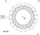
- FIG. 2b An example of an arrangement of the first turbine outlet temperature measurements 18 is shown in Fig. 2b.
- Fig. 2b shows the cross section II - II of Fig. 1 through the annular second combustor 16 with a plurality of burners of the second combustor 25 at the upstream end of the second combustor 16.
- a first turbine outlet temperature measurement 18 is arranged which is connected to the controller 20.
- FIG. 3 shows the cross section III - III of Fig. 1 with the outlet of the second turbine 17.
- a number of second turbine outlet temperature measurement 19 is arranged downstream of the second turbine which is connected to the controller 20.
- the number of second turbine 17 outlet temperature measurements can for example correspond to the number of burners of the second combustor 25 (in this example 20).
- Fig. 4 an example of the exhaust temperature distribution is shown.
- the exhaust temperature is measured at 20 locations which are numbered in clockwise direction from 1 to 20.
- the temperature itself is normalized with the maximum measured temperature.
- the example schematically shows the normalized exhaust temperature distribution for the burner and fuel distribution system shown in Fig. 2a with four burners switched off closest to the 3 o'clock and four burners switched off closest to the 9 o'clock position, i.e. the burners closest to the horizontal plane of the gas turbine are switched off.
- the six burners closest to the 12 o'clock and 6 o'clock (vertical top and bottom of the gas turbine) are operating.
- the operative burners lead to high exhaust temperatures while the exhaust temperature downstream of the inoperative burners is at a minimum.
- the temperature distribution downstream of the turbine is offset in circumferential direction around the axis 26 of the gas turbine relative to the circumverential location of the burners to which a second fuel flow is supplied by an offset angle ⁇ .
- the offset angle ⁇ corresponds to the circumferential offset around the axis 26 of the gas turbine the hotgas is subjected to when traveling from the combustor through the turbine to the location of turbine outlet temperature measurements.
- the offset angle ⁇ in the example of Fig. 4 is 90°. Therefore the location of minimum temperatures is offset by 90° relative to the loaction of the burners which are swichted off and therefore produce the minimum inlet temperatures to the turbine. Analougously, the location of maximum temperatures is offset by 90° relative to the loaction of the burners which are operating with the unrestricted fuel flow and therefore produce the maximum inlet temperatures to the turbine.
- Fig. 5 an exemplary control logic to determine a selected turbine inlet temperature error for the control of the gas turbine is depicted.
- a maximum calculated turbine inlet temperature for the maximum allowable turbine outlet temperature TIT TAT MAX is calculated in a turbine inlet temperature formula block one TIT Formula I.
- the smaller one of the maximum allowable turbine outlet temperature for the maximum allowable turbine outlet temperature TIT TAT MAX and the maximum allowable turbine outlet temperature TAT MAX is selected in the minimum selector I to obtain the selected maximum allowable turbine inlet temperature TIT MAX SEL.
- a turbine inlet temperature TIT is calculated in a turbine inlet temperature formula block two TIT Formula II.
- the maximum trimmed turbine outlet temperature THG TR MAX is calculated in a hot gas temperature calculation block one THG Formula I.
- a trimmed hot gas temperature THG TR is calculated in a hot gas temperature formula block two THG Formula II.
- the difference between the maximum trimmed turbine outlet temperature THG MAX TR and the trimmed hot gas temperature THG TR is determined in the subtraction block II. As a result a trimmed hot gas temperature error THG TR ERR is obtained.
- the a trimmed hot gas temperature error THG TR ERR is converted to a trimmed turbine inlet temperature error TIT TR ERR in the function block for Scaling of hot gas temperature to turbine inlet temperature SCALE.
- the smaller one of the turbine inlet temperature error TIT ERR and the trimmed turbine inlet temperature error TIT TR ERR is selected in the minimum selector II to obtain the selected turbine inlet temperature error TIT ERR SEL.
- the selected turbine inlet temperature error TIT ERR SEL is used for control of the gas turbine, in particular for the control of the fuel flow with the control valve 28 (in Fig. 2a ).
Landscapes
- Engineering & Computer Science (AREA)
- Chemical & Material Sciences (AREA)
- Combustion & Propulsion (AREA)
- Mechanical Engineering (AREA)
- General Engineering & Computer Science (AREA)
- Control Of Turbines (AREA)
- Measuring Temperature Or Quantity Of Heat (AREA)
Priority Applications (4)
| Application Number | Priority Date | Filing Date | Title |
|---|---|---|---|
| EP16152853.4A EP3199781B1 (fr) | 2016-01-27 | 2016-01-27 | Turbine à gaz et procédé correspondant pour commander un fonctionnement d'une turbine à gaz avec des capteurs de température de sortie de turbine sélectionnés |
| CN201710300595.6A CN107201953B (zh) | 2016-01-27 | 2017-01-26 | 根据选定的涡轮机出口温度测量控制燃气涡轮机操作的方法 |
| KR1020170013006A KR20170089787A (ko) | 2016-01-27 | 2017-01-26 | 선택된 터빈 출구 온도 측정부들에 의해서 가스 터빈 작동을 제어하기 위한 방법 |
| US15/418,172 US20170211487A1 (en) | 2016-01-27 | 2017-01-27 | Method for controlling a gas turbine operation with selected turbine outlet temperature measurements |
Applications Claiming Priority (1)
| Application Number | Priority Date | Filing Date | Title |
|---|---|---|---|
| EP16152853.4A EP3199781B1 (fr) | 2016-01-27 | 2016-01-27 | Turbine à gaz et procédé correspondant pour commander un fonctionnement d'une turbine à gaz avec des capteurs de température de sortie de turbine sélectionnés |
Publications (2)
| Publication Number | Publication Date |
|---|---|
| EP3199781A1 true EP3199781A1 (fr) | 2017-08-02 |
| EP3199781B1 EP3199781B1 (fr) | 2019-05-01 |
Family
ID=55272248
Family Applications (1)
| Application Number | Title | Priority Date | Filing Date |
|---|---|---|---|
| EP16152853.4A Active EP3199781B1 (fr) | 2016-01-27 | 2016-01-27 | Turbine à gaz et procédé correspondant pour commander un fonctionnement d'une turbine à gaz avec des capteurs de température de sortie de turbine sélectionnés |
Country Status (4)
| Country | Link |
|---|---|
| US (1) | US20170211487A1 (fr) |
| EP (1) | EP3199781B1 (fr) |
| KR (1) | KR20170089787A (fr) |
| CN (1) | CN107201953B (fr) |
Cited By (1)
| Publication number | Priority date | Publication date | Assignee | Title |
|---|---|---|---|---|
| EP3447379A1 (fr) * | 2017-08-25 | 2019-02-27 | Ansaldo Energia IP UK Limited | Procédé de fonctionnement d'une installation de turbine à gaz et installation de turbine à gaz |
Families Citing this family (6)
| Publication number | Priority date | Publication date | Assignee | Title |
|---|---|---|---|---|
| CN107575310A (zh) * | 2017-10-24 | 2018-01-12 | 江苏华强新能源科技有限公司 | 一种高效燃气轮机出气温度调节系统 |
| EP3702670B1 (fr) * | 2019-02-28 | 2021-12-15 | Ansaldo Energia Switzerland AG | Procédé de fonctionnement d'une chambre de combustion séquentielle d'une turbine à gaz |
| US11396823B2 (en) * | 2019-08-26 | 2022-07-26 | Pratt & Whitney Canada Corp. | System and method for monitoring temperature of a gas turbine engine |
| US11525409B2 (en) | 2020-09-28 | 2022-12-13 | General Electric Company | Temperature based gas turbine control and method |
| EP4206538B1 (fr) * | 2021-12-30 | 2026-02-18 | Ansaldo Energia Switzerland AG | Turbine à gaz avec mesures sélectionnées de la température de sortie de la chambre de combustion et procédé de fonctionnement d'une turbine à gaz |
| CN114719291B (zh) * | 2022-06-08 | 2022-08-26 | 中国航发四川燃气涡轮研究院 | 一种发动机出口温度场控制方法 |
Citations (6)
| Publication number | Priority date | Publication date | Assignee | Title |
|---|---|---|---|---|
| EP0718470A2 (fr) | 1994-12-24 | 1996-06-26 | ABB Management AG | Procédé d'opération d'une turbine à gaz |
| US20060090471A1 (en) * | 2004-11-04 | 2006-05-04 | General Electric Company | Method and apparatus for identification of hot and cold chambers in a gas turbine combustor |
| US20060245914A1 (en) * | 2003-09-01 | 2006-11-02 | Gottfried Adam | Method and device for identifying the operating condition of a turbine |
| EP2071157A1 (fr) | 2007-12-10 | 2009-06-17 | ALSTOM Technology Ltd | Procédé de contrôle d'une turbine à gaz dans une centrale électrique et centrale électrique de mise en oeuvre du procédé |
| EP2469041A1 (fr) * | 2010-12-22 | 2012-06-27 | Siemens Aktiengesellschaft | Procédé de détection d'une condition prédéterminée dans une turbine à gaz et système de détection de défaillance pour turbine à gaz |
| EP2835516A1 (fr) * | 2013-08-08 | 2015-02-11 | Alstom Technology Ltd | Turbine à gaz présentant un meilleur comportement d'émissions en charge partielle |
Family Cites Families (9)
| Publication number | Priority date | Publication date | Assignee | Title |
|---|---|---|---|---|
| US3793826A (en) * | 1972-12-08 | 1974-02-26 | Gen Motors Corp | Electronic start control circuit for gas turbine engine |
| US4058975A (en) * | 1975-12-08 | 1977-11-22 | General Electric Company | Gas turbine temperature sensor validation apparatus and method |
| US20060265174A1 (en) * | 2005-05-18 | 2006-11-23 | Doyle Bruce A | Thermal sensing for integrated circuits |
| US7784263B2 (en) * | 2006-12-05 | 2010-08-31 | General Electric Company | Method for determining sensor locations |
| US9043118B2 (en) * | 2007-04-02 | 2015-05-26 | General Electric Company | Methods and systems for model-based control of gas turbines |
| WO2009109446A1 (fr) * | 2008-03-05 | 2009-09-11 | Alstom Technology Ltd | Procédé de régulation d'une turbine à gaz dans une centrale électrique et centrale électrique destinée à mettre en application le procédé |
| US8370044B2 (en) * | 2009-06-26 | 2013-02-05 | General Electric Company | NOX compliant peak for gas turbine |
| US10041859B2 (en) * | 2014-03-13 | 2018-08-07 | Siemens Energy, Inc. | Parameter distribution mapping in a gas turbine engine |
| US9790834B2 (en) * | 2014-03-20 | 2017-10-17 | General Electric Company | Method of monitoring for combustion anomalies in a gas turbomachine and a gas turbomachine including a combustion anomaly detection system |
-
2016
- 2016-01-27 EP EP16152853.4A patent/EP3199781B1/fr active Active
-
2017
- 2017-01-26 CN CN201710300595.6A patent/CN107201953B/zh active Active
- 2017-01-26 KR KR1020170013006A patent/KR20170089787A/ko not_active Withdrawn
- 2017-01-27 US US15/418,172 patent/US20170211487A1/en not_active Abandoned
Patent Citations (6)
| Publication number | Priority date | Publication date | Assignee | Title |
|---|---|---|---|---|
| EP0718470A2 (fr) | 1994-12-24 | 1996-06-26 | ABB Management AG | Procédé d'opération d'une turbine à gaz |
| US20060245914A1 (en) * | 2003-09-01 | 2006-11-02 | Gottfried Adam | Method and device for identifying the operating condition of a turbine |
| US20060090471A1 (en) * | 2004-11-04 | 2006-05-04 | General Electric Company | Method and apparatus for identification of hot and cold chambers in a gas turbine combustor |
| EP2071157A1 (fr) | 2007-12-10 | 2009-06-17 | ALSTOM Technology Ltd | Procédé de contrôle d'une turbine à gaz dans une centrale électrique et centrale électrique de mise en oeuvre du procédé |
| EP2469041A1 (fr) * | 2010-12-22 | 2012-06-27 | Siemens Aktiengesellschaft | Procédé de détection d'une condition prédéterminée dans une turbine à gaz et système de détection de défaillance pour turbine à gaz |
| EP2835516A1 (fr) * | 2013-08-08 | 2015-02-11 | Alstom Technology Ltd | Turbine à gaz présentant un meilleur comportement d'émissions en charge partielle |
Cited By (3)
| Publication number | Priority date | Publication date | Assignee | Title |
|---|---|---|---|---|
| EP3447379A1 (fr) * | 2017-08-25 | 2019-02-27 | Ansaldo Energia IP UK Limited | Procédé de fonctionnement d'une installation de turbine à gaz et installation de turbine à gaz |
| CN109424445A (zh) * | 2017-08-25 | 2019-03-05 | 安萨尔多能源英国知识产权有限公司 | 用于操作燃气涡轮设备的方法和燃气涡轮设备 |
| CN109424445B (zh) * | 2017-08-25 | 2023-05-16 | 安萨尔多能源英国知识产权有限公司 | 用于操作燃气涡轮设备的方法和燃气涡轮设备 |
Also Published As
| Publication number | Publication date |
|---|---|
| EP3199781B1 (fr) | 2019-05-01 |
| CN107201953A (zh) | 2017-09-26 |
| KR20170089787A (ko) | 2017-08-04 |
| US20170211487A1 (en) | 2017-07-27 |
| CN107201953B (zh) | 2020-12-22 |
Similar Documents
| Publication | Publication Date | Title |
|---|---|---|
| EP3199781B1 (fr) | Turbine à gaz et procédé correspondant pour commander un fonctionnement d'une turbine à gaz avec des capteurs de température de sortie de turbine sélectionnés | |
| EP2959229B1 (fr) | Procédé de fonctionnement d'une turbine à gaz avec combustion étagée et/ou séquentielle | |
| RU2540210C2 (ru) | Способ управления режимом работы газовой турбины на основе температуры выхлопного газа и газовая турбина | |
| EP2597288B1 (fr) | Procédé et appareil permettant d'optimiser le fonctionnement d'un système à turbine sous des charges flexibles | |
| US9708983B2 (en) | Gas turbine with sequential combustion arrangement | |
| US11208959B2 (en) | System and method for flexible fuel usage for gas turbines | |
| CN109424445B (zh) | 用于操作燃气涡轮设备的方法和燃气涡轮设备 | |
| US10767569B2 (en) | Method for controlling the operation of a gas turbine with an averaged turbine outlet temperature | |
| EP2733424A2 (fr) | Système d'alimentation en carburant servant à fournir du carburant à une section de combustion d'une turbine à gaz | |
| US20150040571A1 (en) | Method for fuel split control to a gas turbine using a modified turbine firing temperature | |
| JP2017505403A (ja) | ガスタービンを部分負荷で動作させる方法 | |
| JP2021193298A (ja) | ガスタービンエンジンの拡張された排出量適合動作のためのシステムおよび方法 | |
| US20180266333A1 (en) | Method and system for controlling a sequential gas turbine engine | |
| EP3061945B1 (fr) | Procede pour commander le fonctionnement d'une turbine a gaz a combustion sequentielle | |
| US20140182297A1 (en) | Gas turbine and method of controlling a gas turbine at part-load condition | |
| ITTO20101077A1 (it) | Metodo per controllare un impianto a ciclo combinato in configurazione "single-shaft" e impianto a ciclo combinato in configurazione "single-shaft" | |
| US10221777B2 (en) | Gas turbine combustion control device and combustion control method and program therefor |
Legal Events
| Date | Code | Title | Description |
|---|---|---|---|
| PUAI | Public reference made under article 153(3) epc to a published international application that has entered the european phase |
Free format text: ORIGINAL CODE: 0009012 |
|
| STAA | Information on the status of an ep patent application or granted ep patent |
Free format text: STATUS: THE APPLICATION HAS BEEN PUBLISHED |
|
| AK | Designated contracting states |
Kind code of ref document: A1 Designated state(s): AL AT BE BG CH CY CZ DE DK EE ES FI FR GB GR HR HU IE IS IT LI LT LU LV MC MK MT NL NO PL PT RO RS SE SI SK SM TR |
|
| AX | Request for extension of the european patent |
Extension state: BA ME |
|
| STAA | Information on the status of an ep patent application or granted ep patent |
Free format text: STATUS: REQUEST FOR EXAMINATION WAS MADE |
|
| 17P | Request for examination filed |
Effective date: 20180201 |
|
| RBV | Designated contracting states (corrected) |
Designated state(s): AL AT BE BG CH CY CZ DE DK EE ES FI FR GB GR HR HU IE IS IT LI LT LU LV MC MK MT NL NO PL PT RO RS SE SI SK SM TR |
|
| GRAP | Despatch of communication of intention to grant a patent |
Free format text: ORIGINAL CODE: EPIDOSNIGR1 |
|
| STAA | Information on the status of an ep patent application or granted ep patent |
Free format text: STATUS: GRANT OF PATENT IS INTENDED |
|
| INTG | Intention to grant announced |
Effective date: 20181119 |
|
| GRAS | Grant fee paid |
Free format text: ORIGINAL CODE: EPIDOSNIGR3 |
|
| GRAA | (expected) grant |
Free format text: ORIGINAL CODE: 0009210 |
|
| STAA | Information on the status of an ep patent application or granted ep patent |
Free format text: STATUS: THE PATENT HAS BEEN GRANTED |
|
| AK | Designated contracting states |
Kind code of ref document: B1 Designated state(s): AL AT BE BG CH CY CZ DE DK EE ES FI FR GB GR HR HU IE IS IT LI LT LU LV MC MK MT NL NO PL PT RO RS SE SI SK SM TR |
|
| REG | Reference to a national code |
Ref country code: GB Ref legal event code: FG4D |
|
| REG | Reference to a national code |
Ref country code: CH Ref legal event code: EP Ref country code: AT Ref legal event code: REF Ref document number: 1127223 Country of ref document: AT Kind code of ref document: T Effective date: 20190515 |
|
| REG | Reference to a national code |
Ref country code: DE Ref legal event code: R096 Ref document number: 602016013013 Country of ref document: DE |
|
| REG | Reference to a national code |
Ref country code: IE Ref legal event code: FG4D |
|
| REG | Reference to a national code |
Ref country code: NL Ref legal event code: MP Effective date: 20190501 |
|
| REG | Reference to a national code |
Ref country code: LT Ref legal event code: MG4D |
|
| PG25 | Lapsed in a contracting state [announced via postgrant information from national office to epo] |
Ref country code: PT Free format text: LAPSE BECAUSE OF FAILURE TO SUBMIT A TRANSLATION OF THE DESCRIPTION OR TO PAY THE FEE WITHIN THE PRESCRIBED TIME-LIMIT Effective date: 20190901 Ref country code: ES Free format text: LAPSE BECAUSE OF FAILURE TO SUBMIT A TRANSLATION OF THE DESCRIPTION OR TO PAY THE FEE WITHIN THE PRESCRIBED TIME-LIMIT Effective date: 20190501 Ref country code: AL Free format text: LAPSE BECAUSE OF FAILURE TO SUBMIT A TRANSLATION OF THE DESCRIPTION OR TO PAY THE FEE WITHIN THE PRESCRIBED TIME-LIMIT Effective date: 20190501 Ref country code: SE Free format text: LAPSE BECAUSE OF FAILURE TO SUBMIT A TRANSLATION OF THE DESCRIPTION OR TO PAY THE FEE WITHIN THE PRESCRIBED TIME-LIMIT Effective date: 20190501 Ref country code: HR Free format text: LAPSE BECAUSE OF FAILURE TO SUBMIT A TRANSLATION OF THE DESCRIPTION OR TO PAY THE FEE WITHIN THE PRESCRIBED TIME-LIMIT Effective date: 20190501 Ref country code: LT Free format text: LAPSE BECAUSE OF FAILURE TO SUBMIT A TRANSLATION OF THE DESCRIPTION OR TO PAY THE FEE WITHIN THE PRESCRIBED TIME-LIMIT Effective date: 20190501 Ref country code: NO Free format text: LAPSE BECAUSE OF FAILURE TO SUBMIT A TRANSLATION OF THE DESCRIPTION OR TO PAY THE FEE WITHIN THE PRESCRIBED TIME-LIMIT Effective date: 20190801 Ref country code: FI Free format text: LAPSE BECAUSE OF FAILURE TO SUBMIT A TRANSLATION OF THE DESCRIPTION OR TO PAY THE FEE WITHIN THE PRESCRIBED TIME-LIMIT Effective date: 20190501 Ref country code: NL Free format text: LAPSE BECAUSE OF FAILURE TO SUBMIT A TRANSLATION OF THE DESCRIPTION OR TO PAY THE FEE WITHIN THE PRESCRIBED TIME-LIMIT Effective date: 20190501 |
|
| PG25 | Lapsed in a contracting state [announced via postgrant information from national office to epo] |
Ref country code: LV Free format text: LAPSE BECAUSE OF FAILURE TO SUBMIT A TRANSLATION OF THE DESCRIPTION OR TO PAY THE FEE WITHIN THE PRESCRIBED TIME-LIMIT Effective date: 20190501 Ref country code: RS Free format text: LAPSE BECAUSE OF FAILURE TO SUBMIT A TRANSLATION OF THE DESCRIPTION OR TO PAY THE FEE WITHIN THE PRESCRIBED TIME-LIMIT Effective date: 20190501 Ref country code: BG Free format text: LAPSE BECAUSE OF FAILURE TO SUBMIT A TRANSLATION OF THE DESCRIPTION OR TO PAY THE FEE WITHIN THE PRESCRIBED TIME-LIMIT Effective date: 20190801 Ref country code: GR Free format text: LAPSE BECAUSE OF FAILURE TO SUBMIT A TRANSLATION OF THE DESCRIPTION OR TO PAY THE FEE WITHIN THE PRESCRIBED TIME-LIMIT Effective date: 20190802 |
|
| REG | Reference to a national code |
Ref country code: AT Ref legal event code: MK05 Ref document number: 1127223 Country of ref document: AT Kind code of ref document: T Effective date: 20190501 |
|
| PG25 | Lapsed in a contracting state [announced via postgrant information from national office to epo] |
Ref country code: IS Free format text: LAPSE BECAUSE OF FAILURE TO SUBMIT A TRANSLATION OF THE DESCRIPTION OR TO PAY THE FEE WITHIN THE PRESCRIBED TIME-LIMIT Effective date: 20190901 |
|
| PG25 | Lapsed in a contracting state [announced via postgrant information from national office to epo] |
Ref country code: DK Free format text: LAPSE BECAUSE OF FAILURE TO SUBMIT A TRANSLATION OF THE DESCRIPTION OR TO PAY THE FEE WITHIN THE PRESCRIBED TIME-LIMIT Effective date: 20190501 Ref country code: SK Free format text: LAPSE BECAUSE OF FAILURE TO SUBMIT A TRANSLATION OF THE DESCRIPTION OR TO PAY THE FEE WITHIN THE PRESCRIBED TIME-LIMIT Effective date: 20190501 Ref country code: EE Free format text: LAPSE BECAUSE OF FAILURE TO SUBMIT A TRANSLATION OF THE DESCRIPTION OR TO PAY THE FEE WITHIN THE PRESCRIBED TIME-LIMIT Effective date: 20190501 Ref country code: AT Free format text: LAPSE BECAUSE OF FAILURE TO SUBMIT A TRANSLATION OF THE DESCRIPTION OR TO PAY THE FEE WITHIN THE PRESCRIBED TIME-LIMIT Effective date: 20190501 Ref country code: CZ Free format text: LAPSE BECAUSE OF FAILURE TO SUBMIT A TRANSLATION OF THE DESCRIPTION OR TO PAY THE FEE WITHIN THE PRESCRIBED TIME-LIMIT Effective date: 20190501 Ref country code: RO Free format text: LAPSE BECAUSE OF FAILURE TO SUBMIT A TRANSLATION OF THE DESCRIPTION OR TO PAY THE FEE WITHIN THE PRESCRIBED TIME-LIMIT Effective date: 20190501 |
|
| REG | Reference to a national code |
Ref country code: DE Ref legal event code: R097 Ref document number: 602016013013 Country of ref document: DE |
|
| PG25 | Lapsed in a contracting state [announced via postgrant information from national office to epo] |
Ref country code: IT Free format text: LAPSE BECAUSE OF FAILURE TO SUBMIT A TRANSLATION OF THE DESCRIPTION OR TO PAY THE FEE WITHIN THE PRESCRIBED TIME-LIMIT Effective date: 20190501 Ref country code: SM Free format text: LAPSE BECAUSE OF FAILURE TO SUBMIT A TRANSLATION OF THE DESCRIPTION OR TO PAY THE FEE WITHIN THE PRESCRIBED TIME-LIMIT Effective date: 20190501 |
|
| PLBE | No opposition filed within time limit |
Free format text: ORIGINAL CODE: 0009261 |
|
| STAA | Information on the status of an ep patent application or granted ep patent |
Free format text: STATUS: NO OPPOSITION FILED WITHIN TIME LIMIT |
|
| PG25 | Lapsed in a contracting state [announced via postgrant information from national office to epo] |
Ref country code: TR Free format text: LAPSE BECAUSE OF FAILURE TO SUBMIT A TRANSLATION OF THE DESCRIPTION OR TO PAY THE FEE WITHIN THE PRESCRIBED TIME-LIMIT Effective date: 20190501 |
|
| 26N | No opposition filed |
Effective date: 20200204 |
|
| PG25 | Lapsed in a contracting state [announced via postgrant information from national office to epo] |
Ref country code: PL Free format text: LAPSE BECAUSE OF FAILURE TO SUBMIT A TRANSLATION OF THE DESCRIPTION OR TO PAY THE FEE WITHIN THE PRESCRIBED TIME-LIMIT Effective date: 20190501 |
|
| PG25 | Lapsed in a contracting state [announced via postgrant information from national office to epo] |
Ref country code: SI Free format text: LAPSE BECAUSE OF FAILURE TO SUBMIT A TRANSLATION OF THE DESCRIPTION OR TO PAY THE FEE WITHIN THE PRESCRIBED TIME-LIMIT Effective date: 20190501 |
|
| PG25 | Lapsed in a contracting state [announced via postgrant information from national office to epo] |
Ref country code: MC Free format text: LAPSE BECAUSE OF FAILURE TO SUBMIT A TRANSLATION OF THE DESCRIPTION OR TO PAY THE FEE WITHIN THE PRESCRIBED TIME-LIMIT Effective date: 20190501 |
|
| REG | Reference to a national code |
Ref country code: CH Ref legal event code: PL |
|
| REG | Reference to a national code |
Ref country code: BE Ref legal event code: MM Effective date: 20200131 |
|
| PG25 | Lapsed in a contracting state [announced via postgrant information from national office to epo] |
Ref country code: LU Free format text: LAPSE BECAUSE OF NON-PAYMENT OF DUE FEES Effective date: 20200127 Ref country code: FR Free format text: LAPSE BECAUSE OF NON-PAYMENT OF DUE FEES Effective date: 20200131 |
|
| PG25 | Lapsed in a contracting state [announced via postgrant information from national office to epo] |
Ref country code: BE Free format text: LAPSE BECAUSE OF NON-PAYMENT OF DUE FEES Effective date: 20200131 Ref country code: LI Free format text: LAPSE BECAUSE OF NON-PAYMENT OF DUE FEES Effective date: 20200131 Ref country code: CH Free format text: LAPSE BECAUSE OF NON-PAYMENT OF DUE FEES Effective date: 20200131 |
|
| PG25 | Lapsed in a contracting state [announced via postgrant information from national office to epo] |
Ref country code: IE Free format text: LAPSE BECAUSE OF NON-PAYMENT OF DUE FEES Effective date: 20200127 |
|
| PG25 | Lapsed in a contracting state [announced via postgrant information from national office to epo] |
Ref country code: MT Free format text: LAPSE BECAUSE OF FAILURE TO SUBMIT A TRANSLATION OF THE DESCRIPTION OR TO PAY THE FEE WITHIN THE PRESCRIBED TIME-LIMIT Effective date: 20190501 Ref country code: CY Free format text: LAPSE BECAUSE OF FAILURE TO SUBMIT A TRANSLATION OF THE DESCRIPTION OR TO PAY THE FEE WITHIN THE PRESCRIBED TIME-LIMIT Effective date: 20190501 |
|
| PG25 | Lapsed in a contracting state [announced via postgrant information from national office to epo] |
Ref country code: MK Free format text: LAPSE BECAUSE OF FAILURE TO SUBMIT A TRANSLATION OF THE DESCRIPTION OR TO PAY THE FEE WITHIN THE PRESCRIBED TIME-LIMIT Effective date: 20190501 |
|
| P01 | Opt-out of the competence of the unified patent court (upc) registered |
Effective date: 20240430 |
|
| PGFP | Annual fee paid to national office [announced via postgrant information from national office to epo] |
Ref country code: GB Payment date: 20260122 Year of fee payment: 11 |
|
| PGFP | Annual fee paid to national office [announced via postgrant information from national office to epo] |
Ref country code: DE Payment date: 20260120 Year of fee payment: 11 |