EP3199791A1 - Système de propulsion hybride de réacteur à double flux - Google Patents
Système de propulsion hybride de réacteur à double flux Download PDFInfo
- Publication number
- EP3199791A1 EP3199791A1 EP17151918.4A EP17151918A EP3199791A1 EP 3199791 A1 EP3199791 A1 EP 3199791A1 EP 17151918 A EP17151918 A EP 17151918A EP 3199791 A1 EP3199791 A1 EP 3199791A1
- Authority
- EP
- European Patent Office
- Prior art keywords
- turbine engine
- fuel cell
- gas turbine
- fan
- propulsion system
- Prior art date
- Legal status (The legal status is an assumption and is not a legal conclusion. Google has not performed a legal analysis and makes no representation as to the accuracy of the status listed.)
- Withdrawn
Links
Images


Classifications
-
- F—MECHANICAL ENGINEERING; LIGHTING; HEATING; WEAPONS; BLASTING
- F02—COMBUSTION ENGINES; HOT-GAS OR COMBUSTION-PRODUCT ENGINE PLANTS
- F02C—GAS-TURBINE PLANTS; AIR INTAKES FOR JET-PROPULSION PLANTS; CONTROLLING FUEL SUPPLY IN AIR-BREATHING JET-PROPULSION PLANTS
- F02C6/00—Plural gas-turbine plants; Combinations of gas-turbine plants with other apparatus; Adaptations of gas-turbine plants for special use
-
- F—MECHANICAL ENGINEERING; LIGHTING; HEATING; WEAPONS; BLASTING
- F02—COMBUSTION ENGINES; HOT-GAS OR COMBUSTION-PRODUCT ENGINE PLANTS
- F02C—GAS-TURBINE PLANTS; AIR INTAKES FOR JET-PROPULSION PLANTS; CONTROLLING FUEL SUPPLY IN AIR-BREATHING JET-PROPULSION PLANTS
- F02C7/00—Features, components parts, details or accessories, not provided for in, or of interest apart form groups F02C1/00 - F02C6/00; Air intakes for jet-propulsion plants
- F02C7/12—Cooling of plants
- F02C7/16—Cooling of plants characterised by cooling medium
-
- B—PERFORMING OPERATIONS; TRANSPORTING
- B64—AIRCRAFT; AVIATION; COSMONAUTICS
- B64D—EQUIPMENT FOR FITTING IN OR TO AIRCRAFT; FLIGHT SUITS; PARACHUTES; ARRANGEMENT OR MOUNTING OF POWER PLANTS OR PROPULSION TRANSMISSIONS IN AIRCRAFT
- B64D27/00—Arrangement or mounting of power plants in aircraft; Aircraft characterised by the type or position of power plants
- B64D27/02—Aircraft characterised by the type or position of power plants
- B64D27/30—Aircraft characterised by electric power plants
- B64D27/33—Hybrid electric aircraft
-
- B—PERFORMING OPERATIONS; TRANSPORTING
- B64—AIRCRAFT; AVIATION; COSMONAUTICS
- B64D—EQUIPMENT FOR FITTING IN OR TO AIRCRAFT; FLIGHT SUITS; PARACHUTES; ARRANGEMENT OR MOUNTING OF POWER PLANTS OR PROPULSION TRANSMISSIONS IN AIRCRAFT
- B64D27/00—Arrangement or mounting of power plants in aircraft; Aircraft characterised by the type or position of power plants
- B64D27/02—Aircraft characterised by the type or position of power plants
- B64D27/30—Aircraft characterised by electric power plants
- B64D27/35—Arrangements for on-board electric energy production, distribution, recovery or storage
- B64D27/355—Arrangements for on-board electric energy production, distribution, recovery or storage using fuel cells
-
- B—PERFORMING OPERATIONS; TRANSPORTING
- B64—AIRCRAFT; AVIATION; COSMONAUTICS
- B64D—EQUIPMENT FOR FITTING IN OR TO AIRCRAFT; FLIGHT SUITS; PARACHUTES; ARRANGEMENT OR MOUNTING OF POWER PLANTS OR PROPULSION TRANSMISSIONS IN AIRCRAFT
- B64D35/00—Transmitting power from power plants to propellers or rotors; Arrangements of transmissions
- B64D35/02—Transmitting power from power plants to propellers or rotors; Arrangements of transmissions specially adapted for specific power plants
- B64D35/021—Transmitting power from power plants to propellers or rotors; Arrangements of transmissions specially adapted for specific power plants for electric power plants
- B64D35/022—Transmitting power from power plants to propellers or rotors; Arrangements of transmissions specially adapted for specific power plants for electric power plants of hybrid-electric type
- B64D35/025—Transmitting power from power plants to propellers or rotors; Arrangements of transmissions specially adapted for specific power plants for electric power plants of hybrid-electric type of parallel type
-
- F—MECHANICAL ENGINEERING; LIGHTING; HEATING; WEAPONS; BLASTING
- F02—COMBUSTION ENGINES; HOT-GAS OR COMBUSTION-PRODUCT ENGINE PLANTS
- F02C—GAS-TURBINE PLANTS; AIR INTAKES FOR JET-PROPULSION PLANTS; CONTROLLING FUEL SUPPLY IN AIR-BREATHING JET-PROPULSION PLANTS
- F02C3/00—Gas-turbine plants characterised by the use of combustion products as the working fluid
- F02C3/20—Gas-turbine plants characterised by the use of combustion products as the working fluid using a special fuel, oxidant, or dilution fluid to generate the combustion products
- F02C3/30—Adding water, steam or other fluids for influencing combustion, e.g. to obtain cleaner exhaust gases
- F02C3/305—Increasing the power, speed, torque or efficiency of a gas turbine or the thrust of a turbojet engine by injecting or adding water, steam or other fluids
-
- F—MECHANICAL ENGINEERING; LIGHTING; HEATING; WEAPONS; BLASTING
- F02—COMBUSTION ENGINES; HOT-GAS OR COMBUSTION-PRODUCT ENGINE PLANTS
- F02C—GAS-TURBINE PLANTS; AIR INTAKES FOR JET-PROPULSION PLANTS; CONTROLLING FUEL SUPPLY IN AIR-BREATHING JET-PROPULSION PLANTS
- F02C6/00—Plural gas-turbine plants; Combinations of gas-turbine plants with other apparatus; Adaptations of gas-turbine plants for special use
- F02C6/20—Adaptations of gas-turbine plants for driving vehicles
- F02C6/206—Adaptations of gas-turbine plants for driving vehicles the vehicles being airscrew driven
-
- F—MECHANICAL ENGINEERING; LIGHTING; HEATING; WEAPONS; BLASTING
- F02—COMBUSTION ENGINES; HOT-GAS OR COMBUSTION-PRODUCT ENGINE PLANTS
- F02C—GAS-TURBINE PLANTS; AIR INTAKES FOR JET-PROPULSION PLANTS; CONTROLLING FUEL SUPPLY IN AIR-BREATHING JET-PROPULSION PLANTS
- F02C7/00—Features, components parts, details or accessories, not provided for in, or of interest apart form groups F02C1/00 - F02C6/00; Air intakes for jet-propulsion plants
-
- F—MECHANICAL ENGINEERING; LIGHTING; HEATING; WEAPONS; BLASTING
- F02—COMBUSTION ENGINES; HOT-GAS OR COMBUSTION-PRODUCT ENGINE PLANTS
- F02C—GAS-TURBINE PLANTS; AIR INTAKES FOR JET-PROPULSION PLANTS; CONTROLLING FUEL SUPPLY IN AIR-BREATHING JET-PROPULSION PLANTS
- F02C7/00—Features, components parts, details or accessories, not provided for in, or of interest apart form groups F02C1/00 - F02C6/00; Air intakes for jet-propulsion plants
- F02C7/12—Cooling of plants
-
- F—MECHANICAL ENGINEERING; LIGHTING; HEATING; WEAPONS; BLASTING
- F02—COMBUSTION ENGINES; HOT-GAS OR COMBUSTION-PRODUCT ENGINE PLANTS
- F02C—GAS-TURBINE PLANTS; AIR INTAKES FOR JET-PROPULSION PLANTS; CONTROLLING FUEL SUPPLY IN AIR-BREATHING JET-PROPULSION PLANTS
- F02C7/00—Features, components parts, details or accessories, not provided for in, or of interest apart form groups F02C1/00 - F02C6/00; Air intakes for jet-propulsion plants
- F02C7/36—Power transmission arrangements between the different shafts of the gas turbine plant, or between the gas-turbine plant and the power user
-
- F—MECHANICAL ENGINEERING; LIGHTING; HEATING; WEAPONS; BLASTING
- F02—COMBUSTION ENGINES; HOT-GAS OR COMBUSTION-PRODUCT ENGINE PLANTS
- F02K—JET-PROPULSION PLANTS
- F02K3/00—Plants including a gas turbine driving a compressor or a ducted fan
- F02K3/02—Plants including a gas turbine driving a compressor or a ducted fan in which part of the working fluid by-passes the turbine and combustion chamber
- F02K3/04—Plants including a gas turbine driving a compressor or a ducted fan in which part of the working fluid by-passes the turbine and combustion chamber the plant including ducted fans, i.e. fans with high volume, low pressure outputs, for augmenting the jet thrust, e.g. of double-flow type
- F02K3/06—Plants including a gas turbine driving a compressor or a ducted fan in which part of the working fluid by-passes the turbine and combustion chamber the plant including ducted fans, i.e. fans with high volume, low pressure outputs, for augmenting the jet thrust, e.g. of double-flow type with front fan
-
- H—ELECTRICITY
- H01—ELECTRIC ELEMENTS
- H01M—PROCESSES OR MEANS, e.g. BATTERIES, FOR THE DIRECT CONVERSION OF CHEMICAL ENERGY INTO ELECTRICAL ENERGY
- H01M8/00—Fuel cells; Manufacture thereof
-
- H—ELECTRICITY
- H01—ELECTRIC ELEMENTS
- H01M—PROCESSES OR MEANS, e.g. BATTERIES, FOR THE DIRECT CONVERSION OF CHEMICAL ENERGY INTO ELECTRICAL ENERGY
- H01M8/00—Fuel cells; Manufacture thereof
- H01M8/06—Combination of fuel cells with means for production of reactants or for treatment of residues
- H01M8/0606—Combination of fuel cells with means for production of reactants or for treatment of residues with means for production of gaseous reactants
- H01M8/0612—Combination of fuel cells with means for production of reactants or for treatment of residues with means for production of gaseous reactants from carbon-containing material
- H01M8/0618—Reforming processes, e.g. autothermal, partial oxidation or steam reforming
-
- B—PERFORMING OPERATIONS; TRANSPORTING
- B64—AIRCRAFT; AVIATION; COSMONAUTICS
- B64D—EQUIPMENT FOR FITTING IN OR TO AIRCRAFT; FLIGHT SUITS; PARACHUTES; ARRANGEMENT OR MOUNTING OF POWER PLANTS OR PROPULSION TRANSMISSIONS IN AIRCRAFT
- B64D41/00—Power installations for auxiliary purposes
- B64D2041/005—Fuel cells
-
- F—MECHANICAL ENGINEERING; LIGHTING; HEATING; WEAPONS; BLASTING
- F05—INDEXING SCHEMES RELATING TO ENGINES OR PUMPS IN VARIOUS SUBCLASSES OF CLASSES F01-F04
- F05D—INDEXING SCHEME FOR ASPECTS RELATING TO NON-POSITIVE-DISPLACEMENT MACHINES OR ENGINES, GAS-TURBINES OR JET-PROPULSION PLANTS
- F05D2260/00—Function
- F05D2260/40—Transmission of power
- F05D2260/403—Transmission of power through the shape of the drive components
- F05D2260/4031—Transmission of power through the shape of the drive components as in toothed gearing
- F05D2260/40311—Transmission of power through the shape of the drive components as in toothed gearing of the epicyclical, planetary or differential type
-
- H—ELECTRICITY
- H01—ELECTRIC ELEMENTS
- H01M—PROCESSES OR MEANS, e.g. BATTERIES, FOR THE DIRECT CONVERSION OF CHEMICAL ENERGY INTO ELECTRICAL ENERGY
- H01M2250/00—Fuel cells for particular applications; Specific features of fuel cell system
- H01M2250/20—Fuel cells in motive systems, e.g. vehicle, ship, plane
-
- Y—GENERAL TAGGING OF NEW TECHNOLOGICAL DEVELOPMENTS; GENERAL TAGGING OF CROSS-SECTIONAL TECHNOLOGIES SPANNING OVER SEVERAL SECTIONS OF THE IPC; TECHNICAL SUBJECTS COVERED BY FORMER USPC CROSS-REFERENCE ART COLLECTIONS [XRACs] AND DIGESTS
- Y02—TECHNOLOGIES OR APPLICATIONS FOR MITIGATION OR ADAPTATION AGAINST CLIMATE CHANGE
- Y02T—CLIMATE CHANGE MITIGATION TECHNOLOGIES RELATED TO TRANSPORTATION
- Y02T50/00—Aeronautics or air transport
- Y02T50/60—Efficient propulsion technologies, e.g. for aircraft
Definitions
- the present subject matter relates generally to a hybrid aeronautical propulsion system.
- a gas turbine engine generally includes a fan and a core arranged in flow communication with one another.
- the core of the gas turbine engine generally includes, in serial flow order, a compressor section, a combustion section, a turbine section, and an exhaust section.
- at least a portion of air over the fan is provided to an inlet of the core.
- Such portion of the air is progressively compressed by the compressor section until it reaches the combustion section.
- Fuel is mixed with the compressed air and burned within the combustion section to provide combustion gases.
- the combustion gases are routed from the combustion section through the turbine section to drive one or more turbines within the turbine section.
- the one or more turbines within the turbine section may be coupled to one or more compressors of the compressor section via respective shaft(s).
- the combustion gases are then routed through the exhaust section, e.g., to atmosphere.
- the air Due to the relationship between pressure, temperature, and volume for a gas, as the air is compressed by the compressor section, the air progressively increases in temperature. If the temperature of the air reaches a certain threshold temperature during the compression process, the high temperature air may, e.g., interfere with reliable action of the compressor section and introduce lubrication difficulties, in addition to increasing a required amount of work to compress the air to a given pressure. Such may have a detrimental effect on an efficiency of the compressor section. As a consequence, the compressor section of certain gas turbine engines are not operated to their full potential.
- a gas turbine engine capable of removing heat from the air being compressed by the compressor section during operation of the gas turbine engine would be useful. More specifically, a gas turbine engine capable of removing heat from the air being compressed by the compressor section during operation of the gas turbine engine without requiring the gas turbine engine to carry a dedicated water tank would be particularly beneficial.
- a gas turbine engine in one exemplary embodiment of the present disclosure includes a core turbine engine, a fan mechanically coupled to the core turbine engine, and an electric motor mechanically coupled to at least one of the core turbine engine and the fan.
- the gas turbine engine also includes a fuel cell for providing electrical energy to the electric motor, the fuel cell generating water as a byproduct, the gas turbine engine directing the water generated by the fuel cell to the core turbine engine during operation of the gas turbine engine to improve an efficiency of the gas turbine engine.
- an aeronautical propulsion system including a turbine engine
- the aeronautical propulsion system includes a fan, an electric motor drivingly coupled to the fan, and a fuel cell.
- the fuel cell provides electrical energy to the electric motor and generates water as a byproduct.
- the aeronautical propulsion system directs the water generated by the fuel cell to the turbine engine during operation of the aeronautical propulsion system to improve an efficiency of the aeronautical propulsion system.
- a method of operating an aeronautical propulsion system including a fan, a turbine engine, an electric motor, and a fuel cell.
- the method includes providing mechanical power to at least one of the turbine engine or the fan with the electric motor, and providing electrical energy to the electric motor with the fuel cell.
- the method also includes generating water with the fuel cell as a byproduct of producing electrical energy, and providing the water generated with the fuel cell to the turbine engine of the aeronautical propulsion system.
- FIG. 1 is a schematic cross-sectional view of a gas turbine engine in accordance with an exemplary embodiment of the present disclosure. More particularly, for the embodiment of FIG. 1 , the gas turbine engine is a high-bypass turbofan jet engine 10, referred to herein as "turbofan engine 10." As shown in FIG. 1 , the turbofan engine 10 defines an axial direction A (extending parallel to a longitudinal centerline 12 provided for reference) and a radial direction R. In general, the turbofan 10 includes a fan section 14 and a core turbine engine 16 disposed downstream from the fan section 14.
- the exemplary core turbine engine 16 depicted generally includes a substantially tubular outer casing 18 that defines an annular inlet 20.
- the outer casing 18 encases, in serial flow relationship, a compressor section including a booster or low pressure (LP) compressor 22 and a high pressure (HP) compressor 24; a combustion section 26; a turbine section including a high pressure (HP) turbine 28 and a low pressure (LP) turbine 30; and a jet exhaust nozzle section 32.
- a high pressure (HP) shaft or spool 34 drivingly connects the HP turbine 28 to the HP compressor 24.
- a low pressure (LP) shaft or spool 36 drivingly connects the LP turbine 30 to the LP compressor 22.
- the compressor section, combustion section 26, turbine section, and nozzle section 32 together define a core air flowpath 37.
- the fan section 14 includes a variable pitch fan 38 having a plurality of fan blades 40 coupled to a disk 42 in a spaced apart manner.
- the fan blades 40 extend outwardly from disk 42 generally along the radial direction R.
- Each fan blade 40 is rotatable relative to the disk 42 about a pitch axis P by virtue of the fan blades 40 being operatively coupled to a suitable pitch change mechanism 44 configured to collectively vary the pitch of the fan blades 40 in unison.
- the fan blades 40, disk 42, and pitch change mechanism 44 are together rotatable about the longitudinal axis 12 by LP shaft 36 across a power gear box 46.
- the power gear box 46 includes a plurality of gears for adjusting the rotational speed of the fan 38 relative to the LP shaft 36 to a more efficient rotational fan speed.
- the disk 42 is covered by a rotatable front hub 48 aerodynamically contoured to promote an airflow through the plurality of fan blades 40.
- the exemplary fan section 14 includes an annular fan casing or outer nacelle 50 that circumferentially surrounds the fan 38 and/or at least a portion of the core turbine engine 16.
- the exemplary nacelle 50 is supported relative to the core turbine engine 16 by a plurality of circumferentially-spaced outlet guide vanes 52.
- a downstream section 54 of the nacelle 50 extends over an outer portion of the core turbine engine 16 so as to define a bypass airflow passage 56 therebetween.
- a volume of air 58 enters the turbofan 10 through an associated inlet 60 of the nacelle 50 and/or fan section 14.
- a first portion of the air 58 as indicated by arrows 62 is directed or routed into the bypass airflow passage 56 and a second portion of the air 58 as indicated by arrow 64 is directed or routed into the core air flowpath 37, or more specifically into the LP compressor 22.
- the ratio between the first portion of air 62 and the second portion of air 64 is commonly known as a bypass ratio.
- the bypass ratio may be at least about 8:1.
- the turbofan engine 10 may be referred to as an ultra-high bypass turbofan engine.
- the pressure of the second portion of air 64 is then increased as it is routed through the high pressure (HP) compressor 24 and into the combustion section 26, where it is mixed with fuel and burned to provide combustion gases 66.
- HP high pressure
- the combustion gases 66 are routed through the HP turbine 28 where a portion of thermal and/or kinetic energy from the combustion gases 66 is extracted via sequential stages of HP turbine stator vanes 68 that are coupled to the outer casing 18 and HP turbine rotor blades 70 that are coupled to the HP shaft or spool 34, thus causing the HP shaft or spool 34 to rotate, thereby supporting operation of the HP compressor 24.
- the combustion gases 66 are then routed through the LP turbine 30 where a second portion of thermal and kinetic energy is extracted from the combustion gases 66 via sequential stages of LP turbine stator vanes 72 that are coupled to the outer casing 18 and LP turbine rotor blades 74 that are coupled to the LP shaft or spool 36, thus causing the LP shaft or spool 36 to rotate, thereby supporting operation of the LP compressor 22 and/or rotation of the fan 38.
- the combustion gases 66 are subsequently routed through the jet exhaust nozzle section 32 of the core turbine engine 16 to provide propulsive thrust. Simultaneously, the pressure of the first portion of air 62 is substantially increased as the first portion of air 62 is routed through the bypass airflow passage 56 before it is exhausted from a fan nozzle exhaust section 76 of the turbofan 10, also providing propulsive thrust.
- the HP turbine 28, the LP turbine 30, and the jet exhaust nozzle section 32 at least partially define a hot gas path 78 for routing the combustion gases 66 through the core turbine engine 16.
- the exemplary turbofan engine 10 of FIG. 1 is additionally configured to provide a flow of cooling air from the compressor section to the combustion section 26 and turbine section. More particularly, a flow of bleed air downstream from the LP compressor 22 is directed through a cooling duct 80 to, e.g., the combustor section 26 and the turbine section.
- a cooling duct 80 to, e.g., the combustor section 26 and the turbine section.
- the exemplary cooling airflow and cooling duct 80 is depicted outward of the core air flowpath 37 along the radial direction R, in other embodiments, the cooling airflow and cooling duct 80 may instead be positioned inward of the core air flowpath 37 along the radial direction R. Additionally, in other exemplary embodiments, the cooling airflow may take air from any other location within the compressor section, such as from the LP compressor 22 or HP compressor 24.
- the exemplary turbofan engine 10 depicted in FIG. 1 is configured as an aeronautical gas turbine engine. Aeronautical gas turbine engines, as compared to land-based gas turbine engines, are designed to maximize a power output and efficiency while minimizing an overall weight of the gas turbine engine itself, as well as any required accessory systems.
- turbofan engine 10 depicted in FIG. 1 is provided by way of example only, and that in other exemplary embodiments, the turbofan engine 10 may have any other suitable configuration. It should also be appreciated, that in still other exemplary embodiments, aspects of the present disclosure may be incorporated into any other suitable gas turbine engine. For example, in other exemplary embodiments, aspects of the present disclosure may be incorporated into, e.g., a turboprop engine, a turboshaft engine, or a turbojet engine.
- the aeronautical propulsion system is configured as a gas turbine engine, or more particularly, as a turbofan engine 10.
- gas turbine engine and “turbofan engine” refer generally to the engine itself, as well as any accessory systems.
- the turbofan engine 10 may be configured as an ultra-high bypass, geared, ducted turbofan engine 10, similar to the exemplary turbofan engine 10 described above with reference to FIG. 1 .
- the exemplary turbofan engine 10 generally includes a core turbine engine 16, also referred to herein as simply a turbine engine or core engine, and a fan 38 mechanically coupled to the core turbine engine 16.
- the turbofan engine 10 is configured as a geared and ducted turbofan engine, and accordingly includes a power gearbox 46-the core turbine engine 16 being mechanically coupled to the fan 38 through the power gearbox 46-and an outer nacelle assembly (not shown, see FIG. 1 ) enclosing the fan 38 and at least a portion of the core turbine engine 16.
- the exemplary turbofan engine 10 is also configured as a hybrid gas-electric turbofan engine 10.
- the turbofan engine 10 additionally includes an electric motor 82 mechanically coupled to at least one of the core turbine engine 16 and the fan 38 for at least in part driving at least one of the core turbine engine 16 and fan 38 (i.e., drivingly connected).
- the electric motor 82 is mechanically coupled to the fan 38 through a fan gearbox 84.
- the fan gearbox 84 is depicted as being separate and distinct from the power gearbox 46.
- the fan gearbox 84 and power gearbox 46 may be combined.
- the electric motor 82 may instead be mechanically coupled to the core turbine engine 16, such as to one or both of an LP shaft or an HP shaft (see FIG. 1 ).
- the turbofan engine 10 includes a fuel cell 86 configured to provide electrical energy to the electric motor 82 during at least certain operating conditions of the turbofan engine 10.
- the turbofan engine 10 may include a plurality of fuel cells 86 arranged in a series flow configuration, a parallel flow configuration, or a combination of the two.
- the fuel cell 86 may receive a flow of air through an air duct 88 and utilize hydrogen (i.e., a hydrogen fuel) to generate electrical energy.
- the flow of air through the air duct 88 may come from, e.g., a bypass passage 56 of the turbofan engine 10 (see FIG. 1 ), or any other suitable location.
- the exemplary fuel cell 86 may use hydrogen to generate electricity, typically with a relatively high efficiency, by feeding the fuel cell 86 with hydrogen (or other suitable fuels) and with the oxygen from the flow of air received through the air duct 88.
- the fuel cell 86 may be a proton exchange membrane fuel cell, a solid oxide fuel cell, a direct methanol fuel cell, an alkaline fuel cell, a molten-carbonate fuel cell, or a phosphoric-acid fuel cell.
- the fuel cell 86 may be any suitable electrochemical energy conversion device, such as the electrochemical energy conversion device described in U.S. Patent No. 6,794,080, issued September 21, 2004 , which is incorporated herein fully by reference for all relevant purposes.
- the exemplary turbofan engine 10 depicted includes a reformer 90 (allowing a fuel other than hydrogen to be used) located upstream of the fuel cell 86 for producing a hydrogen fuel for the fuel cell 86.
- the reformer 90 may be in flow communication with a fuel tank 92 of a fuel system of the turbofan engine 10, such that the reformer 90 receives a flow of the same fuel utilized with the core turbine engine 16.
- the fuel system may be configured to provide a first flow of fuel from the fuel tank 92 to the core turbine engine 16 and a second flow of fuel from the fuel tank 92 to the reformer 90.
- the reformer 90 may receive the second flow of fuel from the fuel system and extract the hydrogen compound from such fuel.
- the reformer 90 may then provide the fuel cell 86 with a flow of hydrogen fuel.
- the turbofan engine 10 may be configured to utilize a liquefied natural gas (LNG), aviation turbine fuel (such as Jet A fuel, Jet A-1 fuel), or synthesis gas (i.e., syngas) as its fuel.
- LNG liquefied natural gas
- aviation turbine fuel such as Jet A fuel, Jet A-1 fuel
- synthesis gas i.e., syngas
- the fuel cell 86 provides electrical energy to the electric motor 82 during at least certain operating conditions, such that the electric motor 82 may in turn provided mechanical power to at least one of the fan 38 and the core turbine engine 16.
- the fuel cell 86 may be configured to provide a substantially constant flow of electric power to the electric motor 82 during a takeoff operating mode and/or a climb operating mode.
- the takeoff operating mode and climb operating mode may correspond to, e.g., a "full throttle" operating mode wherein an aircraft into which the turbofan engine 10 is installed is taking off or climbing.
- the fuel cell 86 may be configured to provide a substantially constant flow of electric power to the electric motor 82 during other operating modes, such as a cruise operating mode.
- the cruise operating mode may similarly correspond to an operating mode in which the aircraft having the turbofan engine 10 installed therein is cruising.
- the fuel cell 86 generates water as a byproduct during operation.
- the exemplary turbofan engine 10 depicted is configured to utilize such water to increase an efficiency of the turbofan engine 10.
- the turbofan engine 10 is configured to direct the water generated by the fuel cell 86 to the core turbine engine 16 through an outlet water line 94 during operation to improve an efficiency of the turbofan engine 10, or more particularly, to cool one or more aspects of the turbofan engine 10, or be used as an intercooler fluid between the LP compressor 22 and the HP compressor 24.
- the turbofan engine 10 may be configured to direct the water generated by the fuel cell 86 to the core turbine engine 16 through the outlet water line 94 for intercooling the core turbine engine 16.
- the turbofan engine 10 may be configured to direct the water generated by the fuel cell 86 to a location between a first compressor (e.g., the LP compressor 22) and a second compressor (e.g., the HP compressor 24). More particularly, the turbofan engine 10 may be configured to inject the water directly into the core air flowpath 37 between the LP compressor 22 and HP compressor 24 to reduce a temperature of the airflow therethrough. With such an exemplary embodiment, the water may reduce a temperature of the air by being consumed/ evaporated into the airflow.
- a first compressor e.g., the LP compressor 22
- a second compressor e.g., the HP compressor 24
- the turbofan engine 10 may be configured to inject the water directly into the core air flowpath 37 between the LP compressor 22 and HP compressor 24 to reduce a temperature of the airflow therethrough.
- the water may
- Reducing a temperature of the airflow in the compressor section may allow for the airflow to be compressed to a higher pressure while maintaining such airflow below predetermined temperature limits for the various components within the core turbine engine 16. Additionally, reducing a temperature of the airflow in the compressor section may correspondingly reduce an amount of work required to compress such airflow to a desired pressure and further may reduce an amount of NOx emissions. Thus, reducing a temperature the airflow in the compressor section may contribute to an overall efficiency increase of the core turbine engine 16, and particularly of the compressor section.
- the turbofan engine 10 may utilize the water generated as a byproduct of the fuel cell 86 operation to increase an efficiency of the turbofan engine 10 in any other suitable manner.
- the water may be injected into the core air flowpath 37 at any other suitable location within the compressor section, such as a forward end of the compressor section.
- the water may be circulated through, e.g., one or more stator vanes of the compressor section for cooling an airflow through the compressor section.
- the water may be provided to, e.g., the turbine section in a similar manner to maintain certain components of the turbine section below predetermined temperature thresholds.
- the turbofan engine 10 may be configured to direct/inject the water generated by the fuel cell 86 to the flow of cooling air in the cooling duct 80 from the compressor section.
- the turbofan engine 10 may be configured to direct the water generated by the fuel cell 86 to the flow of cooling air in the cooling duct 80 from the compressor section provided to the combustion section 26 and the turbine section.
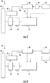
- the exemplary turbofan engine 10 of FIG. 2 is provided by way of example only.
- the turbofan engine 10 may have any other suitable configuration.
- the turbofan engine 10 may not be a geared turbofan engine 10 (i.e., may not include the power gearbox 46 mechanically coupling the fan 38 and the core turbine engine 16), may or may not be a ducted turbofan engine 10 (i.e., may not include a nacelle assembly enclosing the fan 38 and a portion of the core turbine engine 16), and may not be an ultra-high bypass turbofan engine 10 (i.e., may define a bypass ratio of less than about 8:1).
- the turbofan engine 10 may be configured to provide the fuel cell 86 fuel in any other suitable manner.
- the turbofan engine 10 may include a separate, dedicated fuel source for the fuel cell 86.
- the turbofan engine 10 includes a hydrogen fuel tank 96 for providing hydrogen (i.e., hydrogen fuel) to the fuel cell 86.
- the exemplary turbofan engine 10 of FIG. 3 does not include a reformer 90 positioned upstream of the fuel cell 86 or in flow communication with a fuel tank 92 of the fuel system (c.f., FIG. 2 ).
- the turbofan engine 10 of FIG. 3 may in other respects, however, be configured in a substantially similar manner to the exemplary turbofan engine 10 of FIG. 2 .
- the aeronautical propulsion system may not be configured as a single turbofan or other gas turbine engine.
- the aeronautical propulsion system may include a plurality of turbofan engines.
- the aeronautical propulsion system may include a combination of one or more turbofan or other gas turbine engines and one or more other propulsion devices.
- FIG. 4 an aeronautical propulsion system 100 in accordance with still another exemplary embodiment of the present disclosure is provided. Specifically, FIG. 4 provides a schematic, top view of an aircraft 102 having the exemplary aeronautical propulsion system 100 integrated therein.
- the aircraft 102 defines a longitudinal centerline 104 that extends therethrough, a forward end 106, and an aft end 108.
- the aircraft 102 includes a fuselage 110, extending longitudinally from the forward end 106 of the aircraft 102 towards the aft end 108 of the aircraft 102, and a pair of wings 112.
- the first of such wings 112 extends laterally outwardly with respect to the longitudinal centerline 104 from a port side 114 of the fuselage 110 and the second of such wings 112 extends laterally outwardly with respect to the longitudinal centerline 104 from a starboard side 116 of the fuselage 110.
- the aircraft 102 further includes a vertical stabilizer (not shown) and a pair of horizontal stabilizers 120. It should be appreciated however, that in other exemplary embodiments of the present disclosure, the aircraft 102 may additionally or alternatively include any other suitable configuration of stabilizer.
- the exemplary aeronautical propulsion system 100 of FIG. 4 includes a pair of gas turbine aircraft engines, at least one of which mounted to each of the pair of wings 112, and an aft engine.
- the gas turbine aircraft engines are configured as turbofan engines 122, 124 suspended beneath the wings 112 in an under-wing configuration-each turbofan engine 122, 124 including a fan and a turbine engine, also referred to as a core turbine engine (e.g., each of the turbofan engines 122, 124 may be configured in the same manner as the turbofan engine 10 of FIG. 1 ).
- the aft engine may be configured as a fan 126, or more specifically for the embodiment depicted, as a boundary layer ingestion fan configured to ingest and consume air forming a boundary layer over the fuselage 110 of the aircraft 102.
- the exemplary fan 126 depicted is fixedly connected to the fuselage 110 at the aft end 108, such that the fan 126 is incorporated into or blended with a tail section at the aft end 108. Accordingly, the fan 126 may be referred to as an "aft fan.” However, it should be appreciated that in various other embodiments, the fan 126 may alternatively be positioned at any suitable location of the aft end 108.
- the aeronautical propulsion system 100 depicted includes an electric motor 82 mechanically coupled, i.e., drivingly coupled to the fan 126 (via a shaft 128) and a fuel cell 86 for providing electrical energy to the electric motor 82 (via an electrical line 130).
- the fuel cell 86 and electric motor 82 depicted in FIG. 4 may be configured in substantially the same manner as the exemplary fuel cell 86 and electric motor 82 described above with reference to FIG. 2 . Accordingly, during operation of the aeronautical propulsion system 100, or more particularly, during operation of the fuel cell 86, the fuel cell 86 is configured to generate water as a byproduct.
- the aeronautical propulsion system 100 is configured to direct the water generated by the fuel cell 86 as a byproduct to one or both of the turbine engines of the turbofan engines 122, 124 via a water line 132.
- the aeronautical propulsion system may utilize such water to increase an efficiency of the aeronautical propulsion system by, e.g., cooling the turbine engines of the turbofan engines 122, 124.
- An aeronautical portion system in accordance with one or more the above embodiments may be configured to generate thrust in a more efficient manner. More particularly, inclusion of one or more aspects of the present disclosure may allow for an aeronautical propulsion system to increase its efficiency by utilizing a fuel cell to efficiently generate electrical energy and an electric motor to convert such electrical energy to mechanical work for the propulsion system. Additionally, inclusion of one or more aspects of the present disclosure may allow for the aeronautical propulsion system to utilize the water generated by the fuel cell as a byproduct of its operation to further increase an efficiency of the propulsion system.
- inclusion of one or more aspects of the present disclosure may allow the propulsion system to benefit from utilizing consumable water to cool certain aspects of the propulsion system (i.e., a turbine engine of the propulsion system) without requiring an aircraft into which the propulsion system is incorporated to carry a separate tank of water for such use-which may otherwise offset any efficiency gains by utilizing such water.
- the inclusion of one or more aspects of the present disclosure into an ultra-high bypass, geared turbofan engine may result in a particularly high efficiency aeronautical propulsion system.
- the exemplary method (200) generally includes at (202) providing mechanical power to at least one of the turbine engine or the fan with the electric motor. Additionally, the exemplary method (200) includes at (204) providing electrical energy to the electric motor with the fuel cell, and at (206) generating water with the fuel cell as a byproduct of producing electrical energy.
- the exemplary method (200) includes at (208) providing the water generated with the fuel cell at (206) to the turbine engine of the aeronautical propulsion system.
- the water provided to the turbine engine at (208) may be utilized to increase an efficiency of the turbine engine, e.g., by cooling one or more aspects of the turbine engine.
- the turbine engine may include a compressor section and providing the water generated with the fuel cell at (208) may include providing the water generated with the fuel cell to the compressor section of the turbine engine for intercooling the turbine engine.
- the compressor section may include a first compressor and a second compressor located downstream of the first compressor.
- providing the water generated with the fuel cell to the turbine engine at (208) may include providing the water generated with the fuel cell to a location between the first and second compressors.
- turbine engine may additionally include a turbine section and the aeronautical propulsion system may be configured to provide the turbine section with cooling air from the compressor section.
- providing the water generated with the fuel cell to the turbine engine at (208) may include providing/ injecting the water generated with the fuel cell to the cooling air from the compressor section.
Landscapes
- Engineering & Computer Science (AREA)
- Chemical & Material Sciences (AREA)
- Combustion & Propulsion (AREA)
- Mechanical Engineering (AREA)
- General Engineering & Computer Science (AREA)
- Aviation & Aerospace Engineering (AREA)
- Life Sciences & Earth Sciences (AREA)
- Manufacturing & Machinery (AREA)
- Sustainable Development (AREA)
- Sustainable Energy (AREA)
- Chemical Kinetics & Catalysis (AREA)
- Electrochemistry (AREA)
- General Chemical & Material Sciences (AREA)
- Fuel Cell (AREA)
Applications Claiming Priority (1)
| Application Number | Priority Date | Filing Date | Title |
|---|---|---|---|
| US15/006,445 US10774741B2 (en) | 2016-01-26 | 2016-01-26 | Hybrid propulsion system for a gas turbine engine including a fuel cell |
Publications (1)
| Publication Number | Publication Date |
|---|---|
| EP3199791A1 true EP3199791A1 (fr) | 2017-08-02 |
Family
ID=57881965
Family Applications (1)
| Application Number | Title | Priority Date | Filing Date |
|---|---|---|---|
| EP17151918.4A Withdrawn EP3199791A1 (fr) | 2016-01-26 | 2017-01-18 | Système de propulsion hybride de réacteur à double flux |
Country Status (5)
| Country | Link |
|---|---|
| US (1) | US10774741B2 (fr) |
| EP (1) | EP3199791A1 (fr) |
| JP (1) | JP6542812B2 (fr) |
| CN (2) | CN107035530A (fr) |
| CA (1) | CA2954914C (fr) |
Cited By (12)
| Publication number | Priority date | Publication date | Assignee | Title |
|---|---|---|---|---|
| GB2560772A (en) * | 2017-03-23 | 2018-09-26 | Bae Systems Plc | Aircraft including on board electrical power generation system |
| EP3656997A1 (fr) * | 2018-11-21 | 2020-05-27 | United Technologies Corporation | Propulsion électrique hybride avec boîte de vitesses à superposition |
| EP3822171A1 (fr) * | 2019-11-18 | 2021-05-19 | ZeroAvia, Inc. | Moteur hydrogène électrique intégré |
| FR3117093A1 (fr) * | 2020-12-03 | 2022-06-10 | Airbus (S.A.S.) | Système de propulsion électrique d’un aéronef. |
| GB2612973A (en) * | 2021-11-17 | 2023-05-24 | James Roberts Jonathan | Aircraft fuel cell propulsion unit with hybrid jet boost |
| WO2023137230A3 (fr) * | 2022-01-14 | 2023-08-24 | Verdego Aero, Inc. | Groupe motopropulseur hybride parallèle équipé d'un cœur de moteur à turbines |
| US12000404B1 (en) | 2023-08-30 | 2024-06-04 | ZeroAvia, Inc. | Inrunner axial compressor |
| US12341225B2 (en) | 2019-11-17 | 2025-06-24 | ZeroAvia, Inc. | Integrated hydrogen-electric engine |
| US12444939B2 (en) | 2020-09-10 | 2025-10-14 | ZeroAvia, Inc. | Systems and methods for integrated fuel cell stack and battery management for transportation use |
| US12542287B2 (en) | 2019-11-17 | 2026-02-03 | ZeroAvia, Inc. | Fuel tank heat dissipation system for fuel cell cooling |
| US12583607B2 (en) | 2021-03-19 | 2026-03-24 | Verdego Aero, Inc. | Simultaneous air cooling of multiple elements of a hybrid powerplant |
| US12680508B2 (en) | 2022-04-27 | 2026-07-14 | Verdego Aero, Inc. | Hybrid turbofan engine with a planetary gearset for blending power between an electric output and variable-thrust bypass fan |
Families Citing this family (80)
| Publication number | Priority date | Publication date | Assignee | Title |
|---|---|---|---|---|
| US12601276B2 (en) * | 2016-07-01 | 2026-04-14 | Rtx Corporation | High efficiency aircraft parallel hybrid gas turbine electric propulsion system |
| US10393017B2 (en) * | 2017-03-07 | 2019-08-27 | Rolls-Royce Corporation | System and method for reducing specific fuel consumption (SFC) in a turbine powered aircraft |
| US10814955B2 (en) | 2018-02-07 | 2020-10-27 | General Electric Company | Aircraft having an AFT engine |
| US11148820B1 (en) | 2018-02-19 | 2021-10-19 | Parallel Flight Technologies, Inc. | System defining a hybrid power unit for thrust generation in an aerial vehicle and method for controlling the same |
| US10968825B2 (en) | 2018-04-19 | 2021-04-06 | The Boeing Company | Flow multiplier systems for aircraft |
| US10981660B2 (en) * | 2018-04-19 | 2021-04-20 | The Boeing Company | Hybrid propulsion engines for aircraft |
| US11053019B2 (en) | 2018-04-19 | 2021-07-06 | The Boeing Company | Hybrid propulsion engines for aircraft |
| US11168616B2 (en) * | 2018-05-16 | 2021-11-09 | Raytheon Technologies Corporation | Hybrid electric fan with improved low pressure compressor |
| GB201811040D0 (en) * | 2018-07-05 | 2018-08-22 | Rolls Royce Plc | Cooling |
| CN109356750A (zh) * | 2018-11-10 | 2019-02-19 | 天津大学 | 一种用于乘用车的燃料电池耦合发动机喷水的方法 |
| US11530635B2 (en) * | 2018-12-11 | 2022-12-20 | Raytheon Technologies Corporation | Fluid injection systems for gas turbine engines |
| US20200277874A1 (en) * | 2019-03-01 | 2020-09-03 | Pratt & Whitney Canada Corp. | Aircraft propulsion system having hybrid-electric powerplant and combustion powerplant |
| EP3931091B1 (fr) * | 2019-03-01 | 2025-10-29 | Pratt & Whitney Canada Corp. | Configurations de propulsion distribuées pour aéronef ayant des systèmes d'entraînement mixtes |
| US11628942B2 (en) * | 2019-03-01 | 2023-04-18 | Pratt & Whitney Canada Corp. | Torque ripple control for an aircraft power train |
| FR3100799B1 (fr) * | 2019-09-16 | 2021-09-24 | Airbus Operations Sas | Aeronef comportant des etais de soutien pour des ailes dans lesquelles sont agences des conduites d’hydrogene ou des conducteurs electriques |
| DE102019216905B4 (de) * | 2019-11-01 | 2026-02-12 | Deutsches Zentrum für Luft- und Raumfahrt e.V. | Triebwerk für Flugzeuge und Verfahren zum Betreiben |
| US11215117B2 (en) | 2019-11-08 | 2022-01-04 | Raytheon Technologies Corporation | Gas turbine engine having electric motor applying power to the high pressure spool shaft and method for operating same |
| US11511872B2 (en) * | 2020-03-27 | 2022-11-29 | Raytheon Technologies Corporation | Hydrogen propulsion systems for aircraft |
| US11624319B2 (en) * | 2020-05-15 | 2023-04-11 | Pratt & Whitney Canada Corp. | Reverse-flow gas turbine engine with electric motor |
| US11834186B2 (en) * | 2020-08-31 | 2023-12-05 | General Electric Company | Aircraft equipped with a distributed propulsion system having suction and pressure fans |
| DE102020212402A1 (de) * | 2020-09-30 | 2022-03-31 | MTU Aero Engines AG | Vorrichtung und Verfahren zum Kühlen eines Wärmetauschers |
| US11753179B2 (en) * | 2020-10-14 | 2023-09-12 | General Electric Company | Aircraft engines with a fuel cell |
| EP4267464A4 (fr) * | 2020-12-28 | 2024-10-23 | Parallel Flight Technologies, Inc. | Système définissant une unité de puissance hybride permettant la génération de poussée dans un véhicule aérien et son procédé de commande |
| EP4067236B1 (fr) * | 2021-03-29 | 2024-12-25 | Airbus Operations (S.A.S.) | Systeme de propulsion electrique d'un aeronef |
| CA3214218A1 (fr) * | 2021-04-02 | 2022-10-06 | Zeroavia Ltd. | Moteur a turbine hybride a hydrogene-electrique et a hydrogene et systeme |
| DE102021004031A1 (de) | 2021-08-03 | 2023-02-09 | Hans-Martin Striebel | Langstrecken - Verkehrsflugzeug ohne schädliche Emissionen, genannt Care - Liner |
| EP4173956B1 (fr) * | 2021-10-29 | 2026-03-18 | Airbus S.A.S. | Système de propulsion hybride pour propulser un aéronef, son procédé de fonctionnement et aéronef hybride |
| US12202616B2 (en) | 2021-11-04 | 2025-01-21 | General Electric Company | Relight of a propulsion system with a fuel cell |
| US12562579B2 (en) | 2021-11-15 | 2026-02-24 | Kalindha Rashmi LLC | Power generation system employing power amplifying thermo-mechanical inverter technology |
| WO2023101809A1 (fr) | 2021-11-15 | 2023-06-08 | Kalindha Rashmi LLC | Système de génération d'énergie utilisant une technologie d'onduleur thermomécanique à amplification de puissance |
| US11542870B1 (en) | 2021-11-24 | 2023-01-03 | General Electric Company | Gas supply system |
| US20230187677A1 (en) * | 2021-12-14 | 2023-06-15 | General Electric Company | System and method of controlling combustor dynamics with a fuel cell |
| US11719441B2 (en) | 2022-01-04 | 2023-08-08 | General Electric Company | Systems and methods for providing output products to a combustion chamber of a gas turbine engine |
| US11794912B2 (en) | 2022-01-04 | 2023-10-24 | General Electric Company | Systems and methods for reducing emissions with a fuel cell |
| US12037952B2 (en) | 2022-01-04 | 2024-07-16 | General Electric Company | Systems and methods for providing output products to a combustion chamber of a gas turbine engine |
| US12123361B2 (en) | 2022-01-04 | 2024-10-22 | General Electric Company | Systems and methods for providing output products to a combustion chamber of a gas turbine engine |
| US11933216B2 (en) | 2022-01-04 | 2024-03-19 | General Electric Company | Systems and methods for providing output products to a combustion chamber of a gas turbine engine |
| US11970282B2 (en) | 2022-01-05 | 2024-04-30 | General Electric Company | Aircraft thrust management with a fuel cell |
| US12034298B2 (en) | 2022-01-10 | 2024-07-09 | General Electric Company | Power source for an aircraft |
| US11804607B2 (en) | 2022-01-21 | 2023-10-31 | General Electric Company | Cooling of a fuel cell assembly |
| US12351329B2 (en) | 2022-01-21 | 2025-07-08 | General Electric Company | Systems and method of operating a fuel cell assembly |
| US12074350B2 (en) | 2022-01-21 | 2024-08-27 | General Electric Company | Solid oxide fuel cell assembly |
| US12573647B2 (en) | 2022-01-21 | 2026-03-10 | General Electric Company | Solid oxide fuel cell assembly |
| US12037124B2 (en) | 2022-01-21 | 2024-07-16 | General Electric Company | Systems and method of operating a fuel cell assembly |
| US12129789B2 (en) | 2022-02-21 | 2024-10-29 | General Electric Company | Systems and method of operating a fuel cell assembly, a gas turbine engine, or both |
| US11967743B2 (en) | 2022-02-21 | 2024-04-23 | General Electric Company | Modular fuel cell assembly |
| US12170390B2 (en) | 2022-02-21 | 2024-12-17 | General Electric Company | Systems and method of operating a fuel cell assembly, a gas turbine engine, or both |
| US12025061B2 (en) | 2022-04-04 | 2024-07-02 | General Electric Company | Gas turbine engine with fuel cell assembly |
| US20230358166A1 (en) * | 2022-05-04 | 2023-11-09 | Hamilton Sundstrand Corporation | Hydrogen energy conversion system |
| US12412914B2 (en) | 2022-05-16 | 2025-09-09 | General Electric Company | Environmental control system having a fuel cell assembly |
| US12428164B2 (en) | 2022-05-16 | 2025-09-30 | General Electric Company | Environmental control system having a fuel cell assembly |
| US12043406B2 (en) * | 2022-05-27 | 2024-07-23 | General Electric Company | Method of operating a fuel cell assembly for an aircraft |
| US20230411646A1 (en) * | 2022-06-16 | 2023-12-21 | General Electric Company | Fuel cell power system for a vehicle |
| US12006866B2 (en) | 2022-07-08 | 2024-06-11 | Rtx Corporation | Hybrid electric hydrogen engine for aircraft |
| US11817700B1 (en) | 2022-07-20 | 2023-11-14 | General Electric Company | Decentralized electrical power allocation system |
| CN114934857B (zh) * | 2022-07-21 | 2022-12-20 | 中国航发四川燃气涡轮研究院 | 一种变循环涡轮发动机 |
| FR3138409A1 (fr) * | 2022-07-26 | 2024-02-02 | Safran Helicopter Engines | Ensemble propulsif pour aéronef comprenant une machine électrique de propulsion alimentée par une pile à combustible |
| US12301002B2 (en) | 2022-08-26 | 2025-05-13 | General Electric Company | Power dispatch control system for multiple power generation sources |
| US12567595B2 (en) | 2022-11-10 | 2026-03-03 | General Electric Company | Gas turbine combustion section having an integrated fuel cell assembly |
| US12240613B2 (en) | 2022-11-10 | 2025-03-04 | General Electric Company | Gas turbine combustion section having an integrated fuel cell assembly |
| US11923586B1 (en) | 2022-11-10 | 2024-03-05 | General Electric Company | Gas turbine combustion section having an integrated fuel cell assembly |
| US12078350B2 (en) | 2022-11-10 | 2024-09-03 | General Electric Company | Gas turbine combustion section having an integrated fuel cell assembly |
| US11859820B1 (en) | 2022-11-10 | 2024-01-02 | General Electric Company | Gas turbine combustion section having an integrated fuel cell assembly |
| EP4619274A1 (fr) | 2022-11-14 | 2025-09-24 | Joby Aero, Inc. | Architecture électrique hybride |
| US12240615B2 (en) | 2022-12-12 | 2025-03-04 | General Electric Company | Electric propulsor with electric machine in thermal communication with a heat exchanger |
| US12241425B2 (en) * | 2023-02-13 | 2025-03-04 | Pratt & Whitney Canada Corp. | Hybrid electric propulsion system with start sequence and shutdown sequence |
| CN118532266A (zh) | 2023-02-23 | 2024-08-23 | 通用电气公司 | 燃气涡轮发动机和燃料电池组件 |
| CN118532265A (zh) | 2023-02-23 | 2024-08-23 | 通用电气公司 | 燃气涡轮发动机和燃料电池组件 |
| CN118532263A (zh) | 2023-02-23 | 2024-08-23 | 通用电气公司 | 燃气涡轮发动机和燃料电池组件 |
| CN116902207B (zh) * | 2023-07-13 | 2025-08-01 | 西北工业大学 | 一种用于翼身融合飞行器的多电综合能源系统 |
| US12221895B1 (en) * | 2023-08-02 | 2025-02-11 | Rtx Corporation | Steam heated flange for thermal gradient control |
| CN116677498B (zh) * | 2023-08-03 | 2023-10-17 | 中国航发四川燃气涡轮研究院 | 基于氢能的新型高超声速组合发动机 |
| CN119532058B (zh) * | 2023-08-28 | 2025-09-16 | 西北工业大学 | 一种与燃料电池集成的双驱动式旋转爆震发动机 |
| CN119532057A (zh) * | 2023-08-28 | 2025-02-28 | 西北工业大学 | 一种碳氢燃料电池航空发动机 |
| US12215623B1 (en) * | 2023-08-29 | 2025-02-04 | Rtx Corporation | Partial exhaust bottoming cycle |
| FR3160393B1 (fr) * | 2024-03-25 | 2026-07-10 | Safran | Aéronef comportant un système propulsif pourvu d’une pile à combustible à puissance thermique régulée |
| CN117990365B (zh) * | 2024-04-03 | 2024-06-07 | 无锡明阳氢燃动力科技有限公司 | 一种氢燃料燃气轮机的驱动轴转速测试装置 |
| US12421873B1 (en) * | 2024-07-30 | 2025-09-23 | General Electric Company | Propulsion and electrical system for an aircraft including a fuel cell and turbine engine with a steam system |
| US12617537B1 (en) * | 2024-12-23 | 2026-05-05 | The Boeing Company | Hybrid turbofan and solid oxide fuel cell propulsion system and related methods |
| CN120135462B (zh) * | 2025-03-10 | 2025-12-30 | 西北工业大学 | 高紧凑热管理式喷气发动机多模态分体混合推进系统 |
Citations (4)
| Publication number | Priority date | Publication date | Assignee | Title |
|---|---|---|---|---|
| US6794080B2 (en) | 2003-01-10 | 2004-09-21 | General Motors Corporation | Electrochemical energy conversion |
| US20090293494A1 (en) * | 2006-11-29 | 2009-12-03 | Airbus Deutschland Gmbh | Hybrid drive for an aircraft |
| EP2275656A2 (fr) * | 2009-07-15 | 2011-01-19 | Rolls-Royce plc | Système de refroidissement pour air de refroidissement dans un moteur à turbine à gaz |
| DE102013209538A1 (de) * | 2013-05-23 | 2014-11-27 | Robert Bosch Gmbh | Hybridantrieb für kraftgetriebenes Luftfahrzeug, kraftgetriebenes Luftfahrzeug mit Hybridantrieb und zugehöriges Betriebsverfahren |
Family Cites Families (45)
| Publication number | Priority date | Publication date | Assignee | Title |
|---|---|---|---|---|
| SE320600B (fr) | 1965-06-23 | 1970-02-09 | Asea Ab | |
| US4288983A (en) * | 1978-10-19 | 1981-09-15 | United Technologies Corporation | Turbofan engine having core supercharging stage |
| US5106035A (en) * | 1989-12-29 | 1992-04-21 | Aurora Flight Sciences Corporation | Aircraft propulsion system using air liquefaction and storage |
| DE4032993C1 (fr) | 1990-10-15 | 1992-05-07 | Mannesmann Ag, 4000 Duesseldorf, De | |
| US5724806A (en) | 1995-09-11 | 1998-03-10 | General Electric Company | Extracted, cooled, compressed/intercooled, cooling/combustion air for a gas turbine engine |
| US5722241A (en) | 1996-02-26 | 1998-03-03 | Westinghouse Electric Corporation | Integrally intercooled axial compressor and its application to power plants |
| GB9924545D0 (en) * | 1999-10-19 | 1999-12-22 | Rolls Royce Plc | Vehicle main and auxiliary power units |
| JP4300682B2 (ja) | 2000-05-30 | 2009-07-22 | 株式会社島津製作所 | 走行体 |
| US20030230671A1 (en) * | 2000-08-24 | 2003-12-18 | Dunn James P. | Fuel cell powered electric aircraft |
| WO2002038938A1 (fr) | 2000-11-10 | 2002-05-16 | Kovac Marek | Reacteur a turbine a gaz avec derivation et procede de refroidissement pour fluide caloporteur |
| US7550218B2 (en) | 2001-10-11 | 2009-06-23 | Airbus Deutschland Gmbh | Apparatus for producing water onboard of a craft driven by a power plant |
| US6916566B2 (en) * | 2001-10-17 | 2005-07-12 | Ford Motor Company | System and method for rapid preheating of an automotive fuel cell |
| US20070077459A1 (en) * | 2002-05-14 | 2007-04-05 | Walton James F Ii | Compressor-expander with high to idle air flow to fuel cell |
| US7767359B2 (en) | 2002-10-24 | 2010-08-03 | Airbus Deutschland Gmbh | Device for producing water on board of an airplane |
| DE10303341A1 (de) * | 2003-01-29 | 2004-08-26 | Alstom Technology Ltd | Luftkühler für Kraftwerksanlagen sowie Anwendung eines solchen Luftkühlers |
| US6935119B2 (en) * | 2003-03-14 | 2005-08-30 | General Electric Company | Methods for operating gas turbine engines |
| JP4579560B2 (ja) | 2003-06-30 | 2010-11-10 | 川崎重工業株式会社 | 燃料電池・常圧タービン・ハイブリッドシステム |
| US6939633B2 (en) * | 2003-09-17 | 2005-09-06 | General Motors Corporation | Fuel cell shutdown and startup using a cathode recycle loop |
| JP2005304179A (ja) * | 2004-04-12 | 2005-10-27 | Toyota Motor Corp | 駆動システムおよびこれを搭載する移動体 |
| JP4092728B2 (ja) | 2005-01-25 | 2008-05-28 | 独立行政法人 宇宙航空研究開発機構 | 航空機用推進システム |
| EP1696135A1 (fr) | 2005-01-27 | 2006-08-30 | Siemens Aktiengesellschaft | Turbocompresseur avec refroidissement intermédiaire |
| DE102005013824A1 (de) | 2005-03-24 | 2006-10-05 | Airbus Deutschland Gmbh | Versorgungssystem für ein Luftfahrzeug |
| US7428818B2 (en) * | 2005-09-13 | 2008-09-30 | Gas Turbine Efficiency Ab | System and method for augmenting power output from a gas turbine engine |
| DE102006021436A1 (de) | 2006-05-09 | 2007-11-15 | Mtu Aero Engines Gmbh | Gasturbinentriebwerk |
| FR2902759B1 (fr) | 2006-06-27 | 2008-10-24 | Turbomeca | Systeme de generation de puissance pour aeronef utilisant une pile a combustible |
| JP4432958B2 (ja) * | 2006-11-10 | 2010-03-17 | トヨタ自動車株式会社 | 燃料電池を搭載した移動体 |
| US20100062301A1 (en) * | 2006-11-20 | 2010-03-11 | Rudolf Hendriks | System having high-temperature fuel cells |
| DE102006056355A1 (de) * | 2006-11-29 | 2008-06-05 | Airbus Deutschland Gmbh | Antriebsvorrichtung zum Betrieb mit mehreren Kraftstoffen für ein Flugzeug |
| US7981825B2 (en) * | 2008-03-27 | 2011-07-19 | Spansion Llc | Fuel cell catalyst regeneration |
| US7818969B1 (en) * | 2009-12-18 | 2010-10-26 | Energyield, Llc | Enhanced efficiency turbine |
| DE102010021026A1 (de) * | 2010-05-19 | 2011-11-24 | Eads Deutschland Gmbh | Hybrides Antriebs- und Energiesystem für Fluggeräte |
| EP2700120A1 (fr) | 2011-04-21 | 2014-02-26 | Airbus Operations GmbH | Unité d'entraînement, procédé de fourniture de courant et utilisation d'une unité d'entraînement |
| CH705181A1 (de) * | 2011-06-16 | 2012-12-31 | Alstom Technology Ltd | Verfahren zum Kühlen einer Gasturbinenanlage sowie Gasturbinenanlage zur Durchführung des Verfahrens. |
| US8261527B1 (en) * | 2012-01-31 | 2012-09-11 | United Technologies Corporation | Gas turbine engine with geared turbofan and oil thermal management system with unique heat exchanger structure |
| EP2831385B1 (fr) * | 2012-03-28 | 2016-11-09 | General Electric Technology GmbH | Centrale électrique à cycle combiné et méthode d'exploitation d'une telle centrale électrique à cycle combiné |
| US20140123666A1 (en) * | 2012-11-07 | 2014-05-08 | General Electric Company | System to Improve Gas Turbine Output and Hot Gas Path Component Life Utilizing Humid Air for Nozzle Over Cooling |
| WO2014158240A2 (fr) * | 2013-03-14 | 2014-10-02 | Rolls-Royce Corporation | Commande de système de propulsion aéronautique hybride turbo-électrique |
| KR101526402B1 (ko) * | 2013-10-18 | 2015-06-05 | 현대자동차 주식회사 | 연료 전지 차량의 제어 방법 및 시스템 |
| JP6296286B2 (ja) * | 2014-03-24 | 2018-03-20 | 三菱日立パワーシステムズ株式会社 | 排熱回収システム、これを備えているガスタービンプラント、排熱回収方法、及び排熱回収システムの追設方法 |
| EP3197773A4 (fr) * | 2014-09-23 | 2018-02-21 | Sikorsky Aircraft Corporation | Système d'entraînement de puissance électrique hybride pour un giravion |
| US10040566B2 (en) * | 2014-09-23 | 2018-08-07 | Sikorsky Aircraft Corporation | Hybrid contingency power drive system |
| DE102015100185A1 (de) * | 2015-01-08 | 2016-07-14 | Airbus Operations Gmbh | Brennstoffzellensystem für ein Flugzeug und Verfahren zum Bereitstellen eines Inertgases in einem Flugzeug |
| US20160237908A1 (en) * | 2015-02-12 | 2016-08-18 | United Technologies Corporation | Intercooled cooling air using existing heat exchanger |
| US10221862B2 (en) * | 2015-04-24 | 2019-03-05 | United Technologies Corporation | Intercooled cooling air tapped from plural locations |
| US10336461B2 (en) * | 2016-01-05 | 2019-07-02 | The Boeing Company | Aircraft engine and associated method for driving the fan with the low pressure shaft during taxi operations |
-
2016
- 2016-01-26 US US15/006,445 patent/US10774741B2/en active Active
-
2017
- 2017-01-12 CA CA2954914A patent/CA2954914C/fr not_active Expired - Fee Related
- 2017-01-12 JP JP2017003064A patent/JP6542812B2/ja not_active Expired - Fee Related
- 2017-01-18 EP EP17151918.4A patent/EP3199791A1/fr not_active Withdrawn
- 2017-01-25 CN CN201710056164.XA patent/CN107035530A/zh active Pending
- 2017-01-25 CN CN202210721952.7A patent/CN115306562A/zh active Pending
Patent Citations (4)
| Publication number | Priority date | Publication date | Assignee | Title |
|---|---|---|---|---|
| US6794080B2 (en) | 2003-01-10 | 2004-09-21 | General Motors Corporation | Electrochemical energy conversion |
| US20090293494A1 (en) * | 2006-11-29 | 2009-12-03 | Airbus Deutschland Gmbh | Hybrid drive for an aircraft |
| EP2275656A2 (fr) * | 2009-07-15 | 2011-01-19 | Rolls-Royce plc | Système de refroidissement pour air de refroidissement dans un moteur à turbine à gaz |
| DE102013209538A1 (de) * | 2013-05-23 | 2014-11-27 | Robert Bosch Gmbh | Hybridantrieb für kraftgetriebenes Luftfahrzeug, kraftgetriebenes Luftfahrzeug mit Hybridantrieb und zugehöriges Betriebsverfahren |
Cited By (13)
| Publication number | Priority date | Publication date | Assignee | Title |
|---|---|---|---|---|
| GB2560772A (en) * | 2017-03-23 | 2018-09-26 | Bae Systems Plc | Aircraft including on board electrical power generation system |
| EP3656997A1 (fr) * | 2018-11-21 | 2020-05-27 | United Technologies Corporation | Propulsion électrique hybride avec boîte de vitesses à superposition |
| US12341225B2 (en) | 2019-11-17 | 2025-06-24 | ZeroAvia, Inc. | Integrated hydrogen-electric engine |
| US12542287B2 (en) | 2019-11-17 | 2026-02-03 | ZeroAvia, Inc. | Fuel tank heat dissipation system for fuel cell cooling |
| EP3822171A1 (fr) * | 2019-11-18 | 2021-05-19 | ZeroAvia, Inc. | Moteur hydrogène électrique intégré |
| US12444939B2 (en) | 2020-09-10 | 2025-10-14 | ZeroAvia, Inc. | Systems and methods for integrated fuel cell stack and battery management for transportation use |
| FR3117093A1 (fr) * | 2020-12-03 | 2022-06-10 | Airbus (S.A.S.) | Système de propulsion électrique d’un aéronef. |
| US12129039B2 (en) | 2020-12-03 | 2024-10-29 | Airbus Sas | Electric propulsion system of an aircraft |
| US12583607B2 (en) | 2021-03-19 | 2026-03-24 | Verdego Aero, Inc. | Simultaneous air cooling of multiple elements of a hybrid powerplant |
| GB2612973A (en) * | 2021-11-17 | 2023-05-24 | James Roberts Jonathan | Aircraft fuel cell propulsion unit with hybrid jet boost |
| WO2023137230A3 (fr) * | 2022-01-14 | 2023-08-24 | Verdego Aero, Inc. | Groupe motopropulseur hybride parallèle équipé d'un cœur de moteur à turbines |
| US12680508B2 (en) | 2022-04-27 | 2026-07-14 | Verdego Aero, Inc. | Hybrid turbofan engine with a planetary gearset for blending power between an electric output and variable-thrust bypass fan |
| US12000404B1 (en) | 2023-08-30 | 2024-06-04 | ZeroAvia, Inc. | Inrunner axial compressor |
Also Published As
| Publication number | Publication date |
|---|---|
| US20170211474A1 (en) | 2017-07-27 |
| JP6542812B2 (ja) | 2019-07-10 |
| US10774741B2 (en) | 2020-09-15 |
| CA2954914C (fr) | 2019-03-26 |
| JP2017133502A (ja) | 2017-08-03 |
| CA2954914A1 (fr) | 2017-07-26 |
| CN115306562A (zh) | 2022-11-08 |
| CN107035530A (zh) | 2017-08-11 |
Similar Documents
| Publication | Publication Date | Title |
|---|---|---|
| CA2954914C (fr) | Systeme de propulsion hybride | |
| US11673678B2 (en) | Gas-electric propulsion system for an aircraft | |
| US20210262398A1 (en) | Gas turbine engine stall margin management | |
| US12571360B2 (en) | Three-stream gas turbine engine with embedded electric machine | |
| US10450886B2 (en) | Hybrid propulsion system including a chemically rechargeable ultra-capacitor | |
| CN109367794B (zh) | 用于飞行器的推进系统 | |
| US12202616B2 (en) | Relight of a propulsion system with a fuel cell | |
| US20230411646A1 (en) | Fuel cell power system for a vehicle | |
| US20200003115A1 (en) | Turbocharged gas turbine engine with electric power generation for small aircraft electric propulsion | |
| CN116395141A (zh) | 利用燃料电池的飞行器推力管理 | |
| US20250146442A1 (en) | Aircraft system having a thermal management system | |
| US20240426239A1 (en) | Method of generating power with an electric machine | |
| US12025061B2 (en) | Gas turbine engine with fuel cell assembly | |
| US20250277471A1 (en) | Fuel treatment system for hybrid gas-electric propulsion using hydrocarbon fuel | |
| EP4063631A2 (fr) | Système de moteur à turbine équipé d'un système de désoxygénation de carburant et système turboélectrique | |
| CN118529258A (zh) | 燃料箱惰化系统 | |
| EP4726189A1 (fr) | Groupe motopropulseur d'aéronef avec moteur à turbine amplifié et système de pile à combustible | |
| EP4549716A1 (fr) | Système d'aéronef ayant un système de gestion thermique | |
| US12552540B1 (en) | Aircraft air system with electric boost compressor | |
| US12600481B1 (en) | Aircraft air system with boost compressor(s) | |
| US12421873B1 (en) | Propulsion and electrical system for an aircraft including a fuel cell and turbine engine with a steam system | |
| US12516647B2 (en) | Gas turbine engine with third stream | |
| TWM446824U (zh) | 混合動力導風扇引擎 |
Legal Events
| Date | Code | Title | Description |
|---|---|---|---|
| PUAI | Public reference made under article 153(3) epc to a published international application that has entered the european phase |
Free format text: ORIGINAL CODE: 0009012 |
|
| STAA | Information on the status of an ep patent application or granted ep patent |
Free format text: STATUS: THE APPLICATION HAS BEEN PUBLISHED |
|
| AK | Designated contracting states |
Kind code of ref document: A1 Designated state(s): AL AT BE BG CH CY CZ DE DK EE ES FI FR GB GR HR HU IE IS IT LI LT LU LV MC MK MT NL NO PL PT RO RS SE SI SK SM TR |
|
| AX | Request for extension of the european patent |
Extension state: BA ME |
|
| STAA | Information on the status of an ep patent application or granted ep patent |
Free format text: STATUS: REQUEST FOR EXAMINATION WAS MADE |
|
| 17P | Request for examination filed |
Effective date: 20180202 |
|
| RBV | Designated contracting states (corrected) |
Designated state(s): AL AT BE BG CH CY CZ DE DK EE ES FI FR GB GR HR HU IE IS IT LI LT LU LV MC MK MT NL NO PL PT RO RS SE SI SK SM TR |
|
| STAA | Information on the status of an ep patent application or granted ep patent |
Free format text: STATUS: EXAMINATION IS IN PROGRESS |
|
| 17Q | First examination report despatched |
Effective date: 20201211 |
|
| STAA | Information on the status of an ep patent application or granted ep patent |
Free format text: STATUS: THE APPLICATION IS DEEMED TO BE WITHDRAWN |
|
| 18D | Application deemed to be withdrawn |
Effective date: 20210422 |