EP3199808A1 - Machine hydraulique, came annulaire et appareil de génération de puissance de type à énergie renouvelable - Google Patents
Machine hydraulique, came annulaire et appareil de génération de puissance de type à énergie renouvelable Download PDFInfo
- Publication number
- EP3199808A1 EP3199808A1 EP16204306.1A EP16204306A EP3199808A1 EP 3199808 A1 EP3199808 A1 EP 3199808A1 EP 16204306 A EP16204306 A EP 16204306A EP 3199808 A1 EP3199808 A1 EP 3199808A1
- Authority
- EP
- European Patent Office
- Prior art keywords
- cam surface
- cam
- segment
- engagement portion
- hydraulic machine
- Prior art date
- Legal status (The legal status is an assumption and is not a legal conclusion. Google has not performed a legal analysis and makes no representation as to the accuracy of the status listed.)
- Granted
Links
Images



Classifications
-
- F—MECHANICAL ENGINEERING; LIGHTING; HEATING; WEAPONS; BLASTING
- F03—MACHINES OR ENGINES FOR LIQUIDS; WIND, SPRING, OR WEIGHT MOTORS; PRODUCING MECHANICAL POWER OR A REACTIVE PROPULSIVE THRUST, NOT OTHERWISE PROVIDED FOR
- F03C—POSITIVE-DISPLACEMENT ENGINES DRIVEN BY LIQUIDS
- F03C1/00—Reciprocating-piston liquid engines
- F03C1/02—Reciprocating-piston liquid engines with multiple-cylinders, characterised by the number or arrangement of cylinders
- F03C1/04—Reciprocating-piston liquid engines with multiple-cylinders, characterised by the number or arrangement of cylinders with cylinders in star or fan arrangement
- F03C1/053—Reciprocating-piston liquid engines with multiple-cylinders, characterised by the number or arrangement of cylinders with cylinders in star or fan arrangement the pistons co-operating with an actuated element at the inner ends of the cylinders
-
- F—MECHANICAL ENGINEERING; LIGHTING; HEATING; WEAPONS; BLASTING
- F03—MACHINES OR ENGINES FOR LIQUIDS; WIND, SPRING, OR WEIGHT MOTORS; PRODUCING MECHANICAL POWER OR A REACTIVE PROPULSIVE THRUST, NOT OTHERWISE PROVIDED FOR
- F03C—POSITIVE-DISPLACEMENT ENGINES DRIVEN BY LIQUIDS
- F03C1/00—Reciprocating-piston liquid engines
- F03C1/02—Reciprocating-piston liquid engines with multiple-cylinders, characterised by the number or arrangement of cylinders
- F03C1/04—Reciprocating-piston liquid engines with multiple-cylinders, characterised by the number or arrangement of cylinders with cylinders in star or fan arrangement
- F03C1/0403—Details, component parts specially adapted of such engines
- F03C1/0409—Cams
-
- F—MECHANICAL ENGINEERING; LIGHTING; HEATING; WEAPONS; BLASTING
- F04—POSITIVE - DISPLACEMENT MACHINES FOR LIQUIDS; PUMPS FOR LIQUIDS OR ELASTIC FLUIDS
- F04B—POSITIVE-DISPLACEMENT MACHINES FOR LIQUIDS; PUMPS
- F04B1/00—Multi-cylinder machines or pumps characterised by number or arrangement of cylinders
- F04B1/04—Multi-cylinder machines or pumps characterised by number or arrangement of cylinders having cylinders in star- or fan-arrangement
- F04B1/0404—Details or component parts
- F04B1/0413—Cams
-
- F—MECHANICAL ENGINEERING; LIGHTING; HEATING; WEAPONS; BLASTING
- F04—POSITIVE - DISPLACEMENT MACHINES FOR LIQUIDS; PUMPS FOR LIQUIDS OR ELASTIC FLUIDS
- F04B—POSITIVE-DISPLACEMENT MACHINES FOR LIQUIDS; PUMPS
- F04B1/00—Multi-cylinder machines or pumps characterised by number or arrangement of cylinders
- F04B1/04—Multi-cylinder machines or pumps characterised by number or arrangement of cylinders having cylinders in star- or fan-arrangement
- F04B1/053—Multi-cylinder machines or pumps characterised by number or arrangement of cylinders having cylinders in star- or fan-arrangement with actuating or actuated elements at the inner ends of the cylinders
-
- F—MECHANICAL ENGINEERING; LIGHTING; HEATING; WEAPONS; BLASTING
- F04—POSITIVE - DISPLACEMENT MACHINES FOR LIQUIDS; PUMPS FOR LIQUIDS OR ELASTIC FLUIDS
- F04B—POSITIVE-DISPLACEMENT MACHINES FOR LIQUIDS; PUMPS
- F04B1/00—Multi-cylinder machines or pumps characterised by number or arrangement of cylinders
- F04B1/04—Multi-cylinder machines or pumps characterised by number or arrangement of cylinders having cylinders in star- or fan-arrangement
- F04B1/10—Multi-cylinder machines or pumps characterised by number or arrangement of cylinders having cylinders in star- or fan-arrangement the cylinders being movable, e.g. rotary
- F04B1/113—Multi-cylinder machines or pumps characterised by number or arrangement of cylinders having cylinders in star- or fan-arrangement the cylinders being movable, e.g. rotary with actuating or actuated elements at the inner ends of the cylinders
-
- Y—GENERAL TAGGING OF NEW TECHNOLOGICAL DEVELOPMENTS; GENERAL TAGGING OF CROSS-SECTIONAL TECHNOLOGIES SPANNING OVER SEVERAL SECTIONS OF THE IPC; TECHNICAL SUBJECTS COVERED BY FORMER USPC CROSS-REFERENCE ART COLLECTIONS [XRACs] AND DIGESTS
- Y02—TECHNOLOGIES OR APPLICATIONS FOR MITIGATION OR ADAPTATION AGAINST CLIMATE CHANGE
- Y02E—REDUCTION OF GREENHOUSE GAS [GHG] EMISSIONS, RELATED TO ENERGY GENERATION, TRANSMISSION OR DISTRIBUTION
- Y02E10/00—Energy generation through renewable energy sources
- Y02E10/70—Wind energy
- Y02E10/72—Wind turbines with rotation axis in wind direction
Definitions
- the present disclosure relates to a hydraulic machine, a ring cam, and a renewable-energy type power generating apparatus.
- a radial-piston type hydraulic machine may be provided with a ring cam including a plurality of cam segments, as a cam for converting motion between rotational motion of a rotor shaft and reciprocating motion of pistons.
- Patent Document 1 discloses, for example, a ring cam with a plurality of cam segments including a preceding segment and a trailing segment.
- the preceding segment and the trailing segment are arranged adjacently in the rotational direction of the ring cam, and are coupled to each other by engagement between a tongue structure having a protruding shape on the preceding segment and a tongue structure having a recessed shape on the trailing segment.
- Each cam segment has a cam surface that faces pistons.
- Patent Document 1 JP5409920B
- piston rollers piston assemblies
- abrasion may be generated on the piston rollers or on cam surfaces.
- the piston rollers are capable of smooth transition from a cam segment to another.
- Patent Document 1 In connection to a configuration for allowing piston rollers (piston assemblies) to transit smoothly from a cam segment to another, Patent Document 1 merely specifies that piston-facing surfaces at the foremost end of the tongue structure of the trailing segment and at rearmost end of the tongue structure of the preceding segment are recessed from cam working surfaces.
- an object of at least one embodiment of the present invention is to provide a hydraulic machine whereby piston assemblies can transit smoothly from a cam segment to another.
- a hydraulic machine whereby piston assemblies can transit smoothly from a cam segment to another.
- a wind turbine power generating apparatus will be described as an example of application of a hydraulic machine or a hydraulic transmission.
- application of the hydraulic machine or the hydraulic transmission of the present invention may be other power generating apparatuses of renewable energy type such as a tidal current generator, an ocean current generator, and a river current generator, for instance, or may be other apparatuses such as a construction machine. That is, the application is not particularly limited.
- the hydraulic machine may include an inward cam (ring cam), in case of which the embodiments of the present invention also include configurations obtained by reading the following description oppositely with regard to the directions where needed.
- the following description mainly describes a case in which it is the ring cam that rotates, in some embodiments the ring cam may be fixed and the cylinders and pistons may rotate.
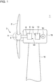
- FIG. 1 is a schematic configuration diagram of a wind turbine power generating apparatus according to an embodiment.
- a wind turbine power generating apparatus 1 includes a rotor 3 including at least one blade 2 and a hub 4.
- the hub 4 may be covered with a hub cover (spinner) 5.
- a hydraulic pump 8 is coupled to the rotor 3 via a rotational shaft 6.
- a hydraulic motor 10 is connected to the hydraulic pump 8 via a high-pressure oil line 12 and a low-pressure oil line 14.
- an outlet of the hydraulic pump 8 is connected to an inlet of the hydraulic motor 10 via the high-pressure oil line 12, and an inlet of the hydraulic pump 8 is connected to an outlet of the hydraulic motor 10 via the low-pressure oil line 14.
- the hydraulic pump 8 As the rotor 3 rotates in response to wind that serves as a renewable energy, the hydraulic pump 8 is driven by rotation of the rotor 3 to increase the pressure of working oil, thereby producing high-pressure working oil (pressurized oil).
- the pressurized oil produced by the hydraulic pump 8 is supplied to the hydraulic motor 10 via the high-pressure oil line 12, and drives the hydraulic motor 10.
- the low-pressure working oil having performed work in the hydraulic motor 10 is returned again to the hydraulic pump 8 via the low-pressure oil line 14 disposed between the outlet of the hydraulic motor 10 and the inlet of the hydraulic pump 8.
- the hydraulic pump 8 and the hydraulic motor 10 constitute a hydraulic transmission.
- the generator 16 is connected to the hydraulic motor 10, and the hydraulic motor 10 drives the generator 16.
- the generator 16 is a synchronous generator connected to a utility grid and driven by the hydraulic motor 10.
- At least a part of the rotational shaft 6 is covered with a nacelle 18 disposed on a tower 19.
- the hydraulic pump 8, the hydraulic motor 10, and the generator 16 are disposed inside the nacelle 18.
- At least one of the hydraulic pump 8 or the hydraulic motor 10 is a radial-piston type hydraulic machine described below.
- FIG. 2 is a cross-sectional view of a hydraulic machine according to an embodiment, taken along a radial direction.
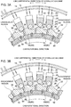
- FIGs. 3A and 3B are each a cross-sectional view of cylinders and surrounding structures thereof in a hydraulic machine according to an embodiment.
- the hydraulic machine 20 depicted in FIG. 2 includes a rotor shaft 30 extending in an axial direction of the hydraulic machine 20, a ring cam 32 extending in a circumferential direction of the hydraulic machine 20 and configured to rotate with the rotor shaft 30, and a plurality of piston assemblies 28.
- Each of the piston assemblies 28 includes a piston 24, and a roller 26 mounted to the piston 24.
- the hydraulic machine 20 further includes a plurality of cylinders 22, and each piston 24 is disposed inside a corresponding one of the plurality of cylinders 22.
- an outward cam (ring cam) 32 of an annular shape is disposed radially outside the rotor shaft 30, and the cylinders 22, the pistons 24, and the rollers 26 are disposed radially outside the outward cam 32.
- an outward cam is a cam having a cam surface to be in contact with the rollers 26 on an outer side in the radial direction.
- an inward cam (ring cam) 32 of an annular shape is disposed radially inside the rotor shaft 30, and the cylinders 22, the pistons 24, and the rollers 26 are disposed radially inside the inward cam 32.
- an inward cam is a cam having a cam surface to be in contact with the rollers 26 on an inner side in the radial direction.
- the plurality of cylinders 22 are arranged in the circumferential direction of the hydraulic machine 20, inside a cylinder block 21.
- the cylinder block 21 may be divided into a plurality of segments 21S in the circumferential direction of the hydraulic machine 20.
- Each piston 24 is disposed slidably inside a corresponding one of the cylinders 22.
- Each piston 24 is guided by the corresponding cylinder 22, so as to reciprocate between a bottom dead center and a top dead center along a center shaft of the cylinder 22.
- the capacity of the working chamber 25 surrounded by the corresponding cylinder 22 and the corresponding piston 24 changes periodically.
- the mode of motion is converted between such reciprocating motion of the pistons 24 accompanied by the periodical capacity change of the working chambers 25 and the rotational motion of the ring cam 32.
- the rotational motion of the ring cam 32 rotating with the rotor shaft 30 of the hydraulic machine 20 is converted into the reciprocating motion of the pistons 24, so that the cyclic volume change of the working chambers 25 takes place and high-pressure working oil (pressurized oil) is produced in the working chambers 25.
- pressurized oil is introduced into the working chambers 25 to cause reciprocating motion of the pistons 24, and the reciprocating motion is converted into the rotational motion of the ring cam 32, so that the rotor shaft 30 of the hydraulic machine 20 rotates with the ring cam 32.
- Each of the rollers 26 is engaged rotatably with a corresponding one of the pistons 24, and is in contact with a cam surface 33 of the ring cam 32.
- the ring cam 32 rotates about a cam center O (center axis of the hydraulic machine 20) together with the rotor shaft 30, each of the rollers 26 runs on the cam surface 33 of the ring cam 32 while rotating.
- the cam surface 33 of the ring cam 32 is formed by a plurality of robes 34 arranged along the circumferential direction of the hydraulic machine 20. Each of the robes 34 protrudes toward the cylinders 22. Each robe 34 is formed by a smooth curve passing through a pair of bottom points 38 and one top point 36 disposed between the pair of bottom points 38. The top points 36 and the bottom points 38 of the robes 34 are positions on the cam surface 33 where the distance from the rotation axis O of the hydraulic machine 20 is the maximum or the minimum, and the top points 36 are disposed closer to the cylinders 22 than the bottom points 38 are to the cylinder 22.
- the top points 36 of the robes 34 are points on the cam surface 33 corresponding to the top dead center in a period of the reciprocating motion of the pistons 24.
- the bottom points 38 of the robes 34 are points on the cam surface 33 corresponding to the bottom dead center in a period of the reciprocating motion of the pistons 24.
- the cylinders 22 are disposed radially outside the outward cam 32.
- the distance (cam diameter) from the center axis (rotation axis of the hydraulic machine 20) O of the outward cam 32 reaches its maximum at the top points 36 of the robes 34, and its minimum at the bottom points 38 of the robes 34.
- the distance from the center axis O of the inward cam to the cam surface 33 reaches its minimum at the top point 36 of the robe 34, and its maximum at the bottom points 38 of the robes 34.
- the normal line to the cam surface 33 is in the same direction as the radial direction of the hydraulic machine 20.
- the hydraulic machine 20 further includes a low-pressure valve 40 disposed between the low-pressure oil line 14 and each of the working chambers 25, and a high-pressure valve 50 disposed between the high-pressure oil line 12 and each of the working chambers 25.
- the low-pressure valve 40 is used to supply the working chambers 25 with low-pressure working oil from the low-pressure oil line 14, and the high-pressure valve 50 is used to supply the high-pressure oil line 12 with high-pressure working oil produced in the working chambers 25.
- the high-pressure valve 50 is used to supply the working chamber 25 with high-pressure working oil from the high-pressure oil line 12, and the low-pressure valve 40 is used to discharge working oil having performed work in the working chamber to the low-pressure oil line.
- the ring cam 32 includes a plurality of cam segments 58 arranged in the circumferential direction of the hydraulic machine 20. At least one pair of adjacent cam segments (60, 60) among the plurality of cam segments 58 includes a preceding segment 60 and a following segment 80 described below.
- the following segment 80 is a cam segment 58 that is subsequent to the preceding segment 60 in the rotational direction of the ring cam 32.
- a facing surface 56 of each segment 58 that faces the rotor shaft 30 is formed by an arc-shaped curved surface as depicted in FIG. 3A .
- the outer peripheral surface of the rotor shaft 30 has a circular shape as seen in the direction of the rotational axis.
- a facing surface 56 of each segment 58 that faces the rotor shaft 30 is formed by a flat surface as depicted in FIG. 3B .
- the outer peripheral surface of the rotor shaft 30 has a polygonal shape as seen in the direction of the rotational axis. As described above, with the facing surfaces 56 formed by flat surfaces, each cam segment 58 can be produced readily.
- each cam segment 58 may be mounted to the rotor shaft 30 via a fixing member 31 such as a bolt, a key, and a pin.
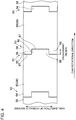
- FIG. 4 is a schematic diagram of a configuration of the preceding segment 60 and the following segment 80 according to an embodiment.
- FIG. 5 is an enlarged view as seen in the direction of a rotational axis, showing an engagement region of the preceding segment 60 and the following segment 80 according to an embodiment.
- FIG. 4 is a view of the preceding segment 60 and the following segment 80, as seen inward in the radial direction of the rotor shaft 30.
- the preceding segment 60 has the first engagement portion 64 protruding toward the following segment 80 at a trailing end portion 62 of the preceding segment 60. Furthermore, the following segment 80 has the second engagement portion 84 protruding toward the preceding segment 60 at a leading end portion 81 of the following segment 80 to be in engagement with the first engagement portion of the preceding segment 60.
- first engagement portion 64 of the preceding segment 60 and the second engagement portion 84 of the following segment 80 are engaged with each other in the engagement region.
- the first engagement portion 64 at the trailing end portion 62 of the preceding segment 60, has the first cam surface 66 facing the rollers 26 (piston assemblies 28).
- the second engagement portion 84 at the leading end portion 81 of the following segment 80, has the second cam surface 86 facing the rollers 26 (piston assemblies 28).
- the first cam surface 66 at the front end 85 of the second cam surface 86, is disposed closer to the piston assemblies 28 than the second cam surface 86 in the radial direction of the hydraulic machine 20, while the first cam surface 66 and the second cam surface 86 intersect with each other in the engagement region between the first engagement portion 64 and the second engagement portion 84.
- first cam surface 66 and the second cam surface 86 intersect with each other at position P 0 , in the engagement region between the first engagement portion 64 and the second engagement portion 84.
- rollers 26 when the rollers 26 (piston assemblies 28) move upstream in the rotational direction of the ring cam 32 on the cam surface 33 in accordance with the rotation of the rotor shaft 30, the rollers 26 are in contact with the first cam surface 66 from the start point of the engagement region (i.e., the position of the front end 85 of the second cam surface 86 in the circumferential direction) to the intersection position P 0 at which the first engagement portion 64 and the second engagement portion 84 intersect with each other in the engagement region, and in contact with the second cam surface 86 from the intersection position P 0 .
- the rollers 26 transit smoothly from the preceding segment 60 to the following segment 80.
- the engagement region has a length in the circumferential direction of the rotor shaft 30.
- the second cam surface 86 at the rear end 65 of the first cam surface 66, is disposed closer to the piston assemblies 28 than the first cam surface 66 with respect to the radial direction of the hydraulic machine 20.
- the rollers 26 come into contact with the second cam surface 86 so as to follow the second cam surface 86 from the intersection position P 0 of the first engagement portion 64 and the second engagement portion 84 to the terminating point of the engagement region (i.e. the position of the rear end 65 of the first cam surface 66 in the circumferential direction), and continuously follows a cam surface 87 of the following segment 80 that is on the backward side of the second engagement portion 84.
- the rollers 26 (piston assemblies 28) transit smoothly from the preceding segment 60 to the following segment 80.
- the preceding segment 60 depicted in FIG. 4 may further have the second engagement portion 84, at a leading end portion 61 of the preceding segment 60, protruding toward a cam segment 58 on the forward side (downstream in the cam rotational direction) of the preceding segment 60 to be in engagement with the cam segment 58.
- the following segment 80 may further have the first engagement portion 64, at a trailing end portion 82 of the following segment 80, protruding toward a cam segment 58 on the backward side (upstream in the cam rotational direction) of the following segment 80 to be in engagement with the cam segment 58.
- each cam segment 58 includes both the first engagement portion 64 and the second engagement portion 84, and thus it is possible to engage adjacent two cam segments 58 with each other in the plurality of cam segments 58 arranged in the circumferential direction.
- the first cam surface 66 of the preceding segment 60 forms a continuous curved surface with the cam surface 67 of a portion on the forward side of the first engagement portion 64 of the preceding segment 60.
- the portion on the forward side of the first engagement portion 64 of the preceding segment 60 refers to a portion of the preceding segment 60, disposed on the forward side (downstream in the cam rotational direction) of the front end 63 of the first engagement portion 64.
- the first cam surface 66 and the cam surface 67 of a portion on the forward side of the first engagement portion form a continuous curved surface, and thereby it is possible for the rollers 26 (piston assemblies 28) to smoothly follow the cam surface of the preceding segment 60 including the first cam surface 66.
- the second cam surface 86 of the following segment 80 forms a continuous curved surface with the cam surface 87 of a portion on the backward side of the second engagement portion 84 of the following segment 80.
- a portion on the backward side of the second engagement portion 84 of the following segment 80 is a portion of the following segment 80, disposed on the backward side (upstream in the cam rotational direction) of the rear end 83 of the second cam surface 86.
- the second cam surface 86 and the cam surface 87 of a portion on the backward side of the second engagement portion form a continuous curved surface, and thereby it is possible for the rollers 26 (piston assemblies 28) to smoothly follow the cam surface of the following segment 80 including the second cam surface 86.
- the first cam surface 66 and the second cam surface 86 intersect with each other within a range of from 0.3L 1 to 0.7L 1 with reference to the rear end 65 of the first cam surface 66.
- the intersection position P 0 between the first cam surface 66 and the second cam surface 86 is within a range of from 0.3L 1 to 0.7L 1 with reference to the rear end 65 of the first cam surface 66.
- the first cam surface 66 and the second cam surface 86 intersect with each other within a range of from 0.3L 2 to 0.7L 2 with reference to the front end 85 of the second cam surface 86.
- the intersection position P 0 between the first cam surface 66 and the second cam surface 86 is within a range of from 0.3L 2 to 0.7L 2 with reference to the front end 85 of the second cam surface 86.
- first cam surface 66 and the second cam surface 86 intersect with each other at a position closer to the center of the first engagement portion 64 with respect to the circumferential direction, or, for the first cam surface 66 and the second cam surface 86 intersect with each other at a position closer to the center of the second engagement portion 84 with respect to the circumferential direction, it is possible to provide a large allowance range for misalignment in the relative positions of the first engagement portion 64 and the second engagement portion 84 in the circumferential direction or the radial direction. Accordingly, it is possible to provide an even larger machining tolerance for the cam segments 58 including the preceding segment 60 and the following segment 80, which makes it possible to produce the ring cam 32 even more readily.
- the cam surface 33 facing the rollers 26 (piston assemblies 28) of the ring cam 32 includes a working surface that comes into contact with the rollers 26 when the pressure of the working chambers 25 is high, and a breathing surface that comes into contact with the rollers 26 (piston assemblies) when the pressure of the working chambers 25 is low.
- the engagement region between the first engagement portion 64 of the preceding segment 60 and the second engagement portion 84 of the following segment 80 is in an extending region of the breathing surface.
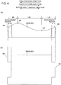
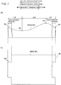
- FIGs. 6 and 7 are each a configuration diagram of the cam segment 58 according to an embodiment, where (A) is a side view and (B) is a top view.
- the low-pressure valve 40 opens and the high-pressure valve 50 closes while the piston 24 moves from the top dead center to the bottom dead center, and thereby the working chamber 25 is supplied with low-pressure working oil.
- the cam surface to be in contact with the roller 26 while the piston 24 moves from the top dead center to the bottom dead center is a cam surface of a low-pressure region (LA), which is the breathing surface.
- the high-pressure valve 50 opens and the low-pressure valve 40 closes while the piston 24 moves from the bottom dead center to the top dead center, and thereby working oil is pressurized in the working chamber 25 and high-pressure working oil is produced.
- the cam surface to be in contact with the roller 26 while the piston 24 moves from the bottom dead center to the top dead center is a cam surface of a high-pressure region (HA), which is the working surface.
- the cam segment 58 depicted in FIG. 6 may be employed as the preceding segment 60 and the following segment 80.
- the cam segment 58 depicted in FIG. 6 includes a top point 36 closest to the piston assemblies 28 with respect to the radial direction of the hydraulic machine 20, and a bottom point 38 furthest from the piston assemblies 28 with respect to the radial direction of the hydraulic machine 20.
- an engagement region is formed on the breathing surface which is a region on the cam surface to be in contact with the roller 26 while the piston 24 moves from the top dead center to the bottom dead center.
- the high-pressure valve 50 opens and the low-pressure valve 40 closes while the piston 24 moves from the top dead center to the bottom dead center, and thereby the working chamber 25 is supplied with high-pressure working oil, thus converting motion of the piston 24 into rotational motion of the ring cam 32.
- the cam surface to be in contact with the roller 26 while the piston 24 moves from the top dead center to the bottom dead center is a cam surface of a high-pressure region (HA), which is the working surface.
- the low-pressure valve 40 opens and the high-pressure valve 50 closes while the piston 24 moves from the bottom dead center to the top dead center, and thereby low-pressure working oil having performed work is discharged from the working chamber 25.
- the cam surface to be in contact with the roller 26 while the piston 24 moves from the bottom dead center to the top dead center is a cam surface of a low-pressure region (LA), which is the breathing surface.
- LA low-pressure region
- the cam segment 58 depicted in FIG. 7 may be employed as the preceding segment 60 and the following segment 80.
- the cam segment 58 depicted in FIG. 7 includes a top point 36 closest to the piston assemblies 28 with respect to the radial direction of the hydraulic machine 20, and a bottom point 38 furthest from the piston assemblies 28 with respect to the radial direction of the hydraulic machine 20.
- an engagement region is formed on the breathing surface which is a region on the cam surface to be in contact with the roller 26 while the piston 24 moves from the bottom dead center to the top dead center.
- the roller 26 transits from the first cam surface 66 of the first engagement portion 64 to the second cam surface 86 of the second engagement portion 84 when the pressure of the working chamber 25 is low.
- the roller 26 transits from the first cam surface 66 of the first engagement portion 64 to the second cam surface 86 of the second engagement portion 84 when the pressure of the working chamber 25 is low.
- the cam surface 33 of the ring cam 32 includes a plurality of top points 36 and a plurality of bottom points 38, which are alternately arranged in the circumferential direction.
- the ring cam 32 is a multi-lobed cam including a plurality of lobes.
- the preceding segment 60 and the following segment 80 each include at least one top point 36 and at least one bottom point 38.
- the hydraulic machine 20 depicted in FIG. 3A or 3B includes the ring cam 32, the preceding segment 60, and the following segment 80 described above.
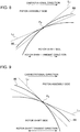
- FIGs. 8 and 9 are each a configuration diagram around an intersection of a first cam surface and a second cam surface according to an embodiment.
- an engagement region between the first engagement portion 64 and the second engagement portion 84 is located in a region of a cam surface where the roller 26 moves from the top point 36 toward the bottom point 38 (i.e. a region where the piston 24 moves from the top dead center toward the bottom dead center).
- an engagement region of the first engagement portion 64 and the second engagement portion 84 is located in a region of a cam surface where the roller 26 moves from the bottom point 38 toward the top point 36 (i.e. a region where the piston 24 moves from the bottom dead center toward the top dead center).
- each of the first cam surface 66 of the first engagement portion 64 and the second cam surface 86 of the second engagement portion 84 has a convex curved surface protruding toward the piston assembly 28.
- the piston assembly 28 can transit from the preceding segment 60 to the following segment 80 even more smoothly.
- FIG. 10 is a diagram for explaining an effect of a cam surface having a convex curved surface, showing a structure similar to that around the intersection between the first cam surface and the second cam surface depicted in FIG. 8 .
- the difference between the gradient of the tangent LP 1 to the first cam surface 66 at position P 1 and the gradient of the tangent L P2 to the second cam surface 86 at position P 2 is smaller than the difference between the gradient of the tangent L 1 to the first cam surface 66 at the intersection position P 0 and the gradient of the tangent L 2 to the second cam surface 86 at the intersection position P 0 .
- the piston assembly 28 can transit from the preceding segment 60 to the following segment 80 smoothly.
- the first tangent L 1 is the tangent to the first cam surface 66 at the position P 0 where the first cam surface 66 and the second cam surface 86 intersect with each other
- the second tangent L 2 is the tangent to the second cam surface 86 at the position P 0
- the first tangent L 1 is closer to the piston assembly 28 than the second tangent L 2 , at the downstream side of the position P 0 in the rotational direction of the ring cam 32.
- the piston assembly 28 can transit even more smoothly from the preceding segment 60 to the following segment 80.
- an expression of relative or absolute arrangement such as “in a direction”, “along a direction”, “parallel”, “orthogonal”, “centered”, “concentric” and “coaxial” shall not be construed as indicating only the arrangement in a strict literal sense, but also includes a state where the arrangement is relatively displaced by a tolerance, or by an angle or a distance whereby it is possible to achieve the same function.
- an expression of an equal state such as “same” “equal” and “uniform” shall not be construed as indicating only the state in which the feature is strictly equal, but also includes a state in which there is a tolerance or a difference that can still achieve the same function.
- an expression of a shape such as a rectangular shape or a cylindrical shape shall not be construed as only the geometrically strict shape, but also includes a shape with unevenness or chamfered corners within the range in which the same effect can be achieved.
Landscapes
- Engineering & Computer Science (AREA)
- Mechanical Engineering (AREA)
- General Engineering & Computer Science (AREA)
- Chemical & Material Sciences (AREA)
- Combustion & Propulsion (AREA)
- Reciprocating Pumps (AREA)
- Hydraulic Motors (AREA)
- Wind Motors (AREA)
Applications Claiming Priority (1)
| Application Number | Priority Date | Filing Date | Title |
|---|---|---|---|
| JP2016012332A JP6444905B2 (ja) | 2016-01-26 | 2016-01-26 | 油圧機械、リングカム及び再生可能エネルギー型発電装置 |
Publications (2)
| Publication Number | Publication Date |
|---|---|
| EP3199808A1 true EP3199808A1 (fr) | 2017-08-02 |
| EP3199808B1 EP3199808B1 (fr) | 2021-08-11 |
Family
ID=57570194
Family Applications (1)
| Application Number | Title | Priority Date | Filing Date |
|---|---|---|---|
| EP16204306.1A Active EP3199808B1 (fr) | 2016-01-26 | 2016-12-15 | Machine hydraulique, came annulaire et appareil de génération de puissance de type à énergie renouvelable |
Country Status (2)
| Country | Link |
|---|---|
| EP (1) | EP3199808B1 (fr) |
| JP (1) | JP6444905B2 (fr) |
Citations (5)
| Publication number | Priority date | Publication date | Assignee | Title |
|---|---|---|---|---|
| EP0692071B1 (fr) * | 1993-03-30 | 1998-09-23 | Ulf Henricson | Systeme d'actionnement hydraulique |
| US20120059523A1 (en) * | 2010-02-23 | 2012-03-08 | Artemis Intelligent Power Limited | Fluid-working machine and method of operating a fluid-working machine |
| US20120260765A1 (en) * | 2010-08-17 | 2012-10-18 | Artemis Intelligent Power Limited | Ring cam and fluid-working machine including ring cam |
| JP5409920B2 (ja) | 2010-08-17 | 2014-02-05 | アルテミス インテリジェント パワー リミティド | リングカムおよびリングカムを含む流体作動機械 |
| EP2529112B1 (fr) * | 2010-02-23 | 2015-08-19 | Artemis Intelligent Power Limited | Machine à fluide à pistons radiaux à déplacement variable |
-
2016
- 2016-01-26 JP JP2016012332A patent/JP6444905B2/ja not_active Expired - Fee Related
- 2016-12-15 EP EP16204306.1A patent/EP3199808B1/fr active Active
Patent Citations (5)
| Publication number | Priority date | Publication date | Assignee | Title |
|---|---|---|---|---|
| EP0692071B1 (fr) * | 1993-03-30 | 1998-09-23 | Ulf Henricson | Systeme d'actionnement hydraulique |
| US20120059523A1 (en) * | 2010-02-23 | 2012-03-08 | Artemis Intelligent Power Limited | Fluid-working machine and method of operating a fluid-working machine |
| EP2529112B1 (fr) * | 2010-02-23 | 2015-08-19 | Artemis Intelligent Power Limited | Machine à fluide à pistons radiaux à déplacement variable |
| US20120260765A1 (en) * | 2010-08-17 | 2012-10-18 | Artemis Intelligent Power Limited | Ring cam and fluid-working machine including ring cam |
| JP5409920B2 (ja) | 2010-08-17 | 2014-02-05 | アルテミス インテリジェント パワー リミティド | リングカムおよびリングカムを含む流体作動機械 |
Also Published As
| Publication number | Publication date |
|---|---|
| JP6444905B2 (ja) | 2018-12-26 |
| JP2017133389A (ja) | 2017-08-03 |
| EP3199808B1 (fr) | 2021-08-11 |
Similar Documents
| Publication | Publication Date | Title |
|---|---|---|
| US8358024B2 (en) | Wind turbine generator and tidal current generator with a hydraulic transmission | |
| US6700280B1 (en) | Drive unit with an electric machine | |
| EP2766601B1 (fr) | Générateur à turbine éolienne | |
| EP3101270B1 (fr) | Dispositif pour inverser une pale d'une unité de rotor | |
| EP3318753B1 (fr) | Appareil de production de puissance de type à énergie renouvelable et procédé d'assemblage correspondant | |
| EP2821638B1 (fr) | Générateur d'énergie renouvelable | |
| EP3199808B1 (fr) | Machine hydraulique, came annulaire et appareil de génération de puissance de type à énergie renouvelable | |
| EP2955374B1 (fr) | Machine hydraulique à pistons radiaux et appareil de génération d'énergie éolienne | |
| EP3104006B1 (fr) | Machine hydraulique et appareil de génération de puissance de type à énergie renouvelable | |
| EP2821648B1 (fr) | Machine hydraulique et dispositif de génération de puissance à énergie récupérée | |
| EP3141748B1 (fr) | Machine hydraulique de type pistons radiaux et appareil de génération d'énergie éolienne | |
| US10598144B2 (en) | Device for reversing a blade of a runner unit | |
| EP2749768B1 (fr) | Machine hydraulique à pistons radiaux et générateur de turbine éolienne | |
| CN113167274A (zh) | 吸气/压缩旋转机构、旋转式压缩机和旋转式发动机 | |
| JP6475538B2 (ja) | 油圧機械及び再生エネルギー型発電装置 | |
| US9863408B2 (en) | Slipper retainer for hydraulic unit | |
| EP3211228B1 (fr) | Machine hydraulique et appareil de génération d'énergie éolienne | |
| RU2154167C1 (ru) | Поршневая машина | |
| US9719499B2 (en) | Slipper retainer ball for hydraulic unit | |
| JP6466995B2 (ja) | ラジアルピストン式油圧機械及び風力発電装置 | |
| EP3061965B1 (fr) | Bague externe de palier à roulement d'une unité hydraulique | |
| EP2781744A2 (fr) | Machine hydraulique à pistons radiaux et générateur de turbine éolienne |
Legal Events
| Date | Code | Title | Description |
|---|---|---|---|
| PUAI | Public reference made under article 153(3) epc to a published international application that has entered the european phase |
Free format text: ORIGINAL CODE: 0009012 |
|
| STAA | Information on the status of an ep patent application or granted ep patent |
Free format text: STATUS: THE APPLICATION HAS BEEN PUBLISHED |
|
| AK | Designated contracting states |
Kind code of ref document: A1 Designated state(s): AL AT BE BG CH CY CZ DE DK EE ES FI FR GB GR HR HU IE IS IT LI LT LU LV MC MK MT NL NO PL PT RO RS SE SI SK SM TR |
|
| AX | Request for extension of the european patent |
Extension state: BA ME |
|
| STAA | Information on the status of an ep patent application or granted ep patent |
Free format text: STATUS: REQUEST FOR EXAMINATION WAS MADE |
|
| 17P | Request for examination filed |
Effective date: 20171113 |
|
| RBV | Designated contracting states (corrected) |
Designated state(s): AL AT BE BG CH CY CZ DE DK EE ES FI FR GB GR HR HU IE IS IT LI LT LU LV MC MK MT NL NO PL PT RO RS SE SI SK SM TR |
|
| GRAP | Despatch of communication of intention to grant a patent |
Free format text: ORIGINAL CODE: EPIDOSNIGR1 |
|
| STAA | Information on the status of an ep patent application or granted ep patent |
Free format text: STATUS: GRANT OF PATENT IS INTENDED |
|
| RIC1 | Information provided on ipc code assigned before grant |
Ipc: F04B 41/04 20060101ALI20210316BHEP Ipc: F03C 1/053 20060101ALI20210316BHEP Ipc: F03C 1/30 20060101ALI20210316BHEP Ipc: F04B 1/113 20200101ALI20210316BHEP Ipc: F04B 1/053 20200101ALI20210316BHEP Ipc: F04B 1/04 20200101AFI20210316BHEP |
|
| INTG | Intention to grant announced |
Effective date: 20210330 |
|
| GRAS | Grant fee paid |
Free format text: ORIGINAL CODE: EPIDOSNIGR3 |
|
| GRAA | (expected) grant |
Free format text: ORIGINAL CODE: 0009210 |
|
| STAA | Information on the status of an ep patent application or granted ep patent |
Free format text: STATUS: THE PATENT HAS BEEN GRANTED |
|
| AK | Designated contracting states |
Kind code of ref document: B1 Designated state(s): AL AT BE BG CH CY CZ DE DK EE ES FI FR GB GR HR HU IE IS IT LI LT LU LV MC MK MT NL NO PL PT RO RS SE SI SK SM TR |
|
| REG | Reference to a national code |
Ref country code: CH Ref legal event code: EP |
|
| REG | Reference to a national code |
Ref country code: DE Ref legal event code: R096 Ref document number: 602016061925 Country of ref document: DE |
|
| REG | Reference to a national code |
Ref country code: IE Ref legal event code: FG4D Ref country code: AT Ref legal event code: REF Ref document number: 1419633 Country of ref document: AT Kind code of ref document: T Effective date: 20210915 |
|
| REG | Reference to a national code |
Ref country code: LT Ref legal event code: MG9D |
|
| REG | Reference to a national code |
Ref country code: NL Ref legal event code: MP Effective date: 20210811 |
|
| REG | Reference to a national code |
Ref country code: AT Ref legal event code: MK05 Ref document number: 1419633 Country of ref document: AT Kind code of ref document: T Effective date: 20210811 |
|
| PG25 | Lapsed in a contracting state [announced via postgrant information from national office to epo] |
Ref country code: NO Free format text: LAPSE BECAUSE OF FAILURE TO SUBMIT A TRANSLATION OF THE DESCRIPTION OR TO PAY THE FEE WITHIN THE PRESCRIBED TIME-LIMIT Effective date: 20211111 Ref country code: PT Free format text: LAPSE BECAUSE OF FAILURE TO SUBMIT A TRANSLATION OF THE DESCRIPTION OR TO PAY THE FEE WITHIN THE PRESCRIBED TIME-LIMIT Effective date: 20211213 Ref country code: HR Free format text: LAPSE BECAUSE OF FAILURE TO SUBMIT A TRANSLATION OF THE DESCRIPTION OR TO PAY THE FEE WITHIN THE PRESCRIBED TIME-LIMIT Effective date: 20210811 Ref country code: FI Free format text: LAPSE BECAUSE OF FAILURE TO SUBMIT A TRANSLATION OF THE DESCRIPTION OR TO PAY THE FEE WITHIN THE PRESCRIBED TIME-LIMIT Effective date: 20210811 Ref country code: ES Free format text: LAPSE BECAUSE OF FAILURE TO SUBMIT A TRANSLATION OF THE DESCRIPTION OR TO PAY THE FEE WITHIN THE PRESCRIBED TIME-LIMIT Effective date: 20210811 Ref country code: LT Free format text: LAPSE BECAUSE OF FAILURE TO SUBMIT A TRANSLATION OF THE DESCRIPTION OR TO PAY THE FEE WITHIN THE PRESCRIBED TIME-LIMIT Effective date: 20210811 Ref country code: AT Free format text: LAPSE BECAUSE OF FAILURE TO SUBMIT A TRANSLATION OF THE DESCRIPTION OR TO PAY THE FEE WITHIN THE PRESCRIBED TIME-LIMIT Effective date: 20210811 Ref country code: BG Free format text: LAPSE BECAUSE OF FAILURE TO SUBMIT A TRANSLATION OF THE DESCRIPTION OR TO PAY THE FEE WITHIN THE PRESCRIBED TIME-LIMIT Effective date: 20211111 Ref country code: SE Free format text: LAPSE BECAUSE OF FAILURE TO SUBMIT A TRANSLATION OF THE DESCRIPTION OR TO PAY THE FEE WITHIN THE PRESCRIBED TIME-LIMIT Effective date: 20210811 Ref country code: RS Free format text: LAPSE BECAUSE OF FAILURE TO SUBMIT A TRANSLATION OF THE DESCRIPTION OR TO PAY THE FEE WITHIN THE PRESCRIBED TIME-LIMIT Effective date: 20210811 |
|
| PG25 | Lapsed in a contracting state [announced via postgrant information from national office to epo] |
Ref country code: PL Free format text: LAPSE BECAUSE OF FAILURE TO SUBMIT A TRANSLATION OF THE DESCRIPTION OR TO PAY THE FEE WITHIN THE PRESCRIBED TIME-LIMIT Effective date: 20210811 Ref country code: LV Free format text: LAPSE BECAUSE OF FAILURE TO SUBMIT A TRANSLATION OF THE DESCRIPTION OR TO PAY THE FEE WITHIN THE PRESCRIBED TIME-LIMIT Effective date: 20210811 Ref country code: GR Free format text: LAPSE BECAUSE OF FAILURE TO SUBMIT A TRANSLATION OF THE DESCRIPTION OR TO PAY THE FEE WITHIN THE PRESCRIBED TIME-LIMIT Effective date: 20211112 |
|
| PG25 | Lapsed in a contracting state [announced via postgrant information from national office to epo] |
Ref country code: NL Free format text: LAPSE BECAUSE OF FAILURE TO SUBMIT A TRANSLATION OF THE DESCRIPTION OR TO PAY THE FEE WITHIN THE PRESCRIBED TIME-LIMIT Effective date: 20210811 |
|
| PG25 | Lapsed in a contracting state [announced via postgrant information from national office to epo] |
Ref country code: DK Free format text: LAPSE BECAUSE OF FAILURE TO SUBMIT A TRANSLATION OF THE DESCRIPTION OR TO PAY THE FEE WITHIN THE PRESCRIBED TIME-LIMIT Effective date: 20210811 |
|
| REG | Reference to a national code |
Ref country code: DE Ref legal event code: R097 Ref document number: 602016061925 Country of ref document: DE |
|
| PG25 | Lapsed in a contracting state [announced via postgrant information from national office to epo] |
Ref country code: SM Free format text: LAPSE BECAUSE OF FAILURE TO SUBMIT A TRANSLATION OF THE DESCRIPTION OR TO PAY THE FEE WITHIN THE PRESCRIBED TIME-LIMIT Effective date: 20210811 Ref country code: SK Free format text: LAPSE BECAUSE OF FAILURE TO SUBMIT A TRANSLATION OF THE DESCRIPTION OR TO PAY THE FEE WITHIN THE PRESCRIBED TIME-LIMIT Effective date: 20210811 Ref country code: RO Free format text: LAPSE BECAUSE OF FAILURE TO SUBMIT A TRANSLATION OF THE DESCRIPTION OR TO PAY THE FEE WITHIN THE PRESCRIBED TIME-LIMIT Effective date: 20210811 Ref country code: EE Free format text: LAPSE BECAUSE OF FAILURE TO SUBMIT A TRANSLATION OF THE DESCRIPTION OR TO PAY THE FEE WITHIN THE PRESCRIBED TIME-LIMIT Effective date: 20210811 Ref country code: CZ Free format text: LAPSE BECAUSE OF FAILURE TO SUBMIT A TRANSLATION OF THE DESCRIPTION OR TO PAY THE FEE WITHIN THE PRESCRIBED TIME-LIMIT Effective date: 20210811 Ref country code: AL Free format text: LAPSE BECAUSE OF FAILURE TO SUBMIT A TRANSLATION OF THE DESCRIPTION OR TO PAY THE FEE WITHIN THE PRESCRIBED TIME-LIMIT Effective date: 20210811 |
|
| PLBE | No opposition filed within time limit |
Free format text: ORIGINAL CODE: 0009261 |
|
| STAA | Information on the status of an ep patent application or granted ep patent |
Free format text: STATUS: NO OPPOSITION FILED WITHIN TIME LIMIT |
|
| 26N | No opposition filed |
Effective date: 20220512 |
|
| PG25 | Lapsed in a contracting state [announced via postgrant information from national office to epo] |
Ref country code: MC Free format text: LAPSE BECAUSE OF FAILURE TO SUBMIT A TRANSLATION OF THE DESCRIPTION OR TO PAY THE FEE WITHIN THE PRESCRIBED TIME-LIMIT Effective date: 20210811 Ref country code: IT Free format text: LAPSE BECAUSE OF FAILURE TO SUBMIT A TRANSLATION OF THE DESCRIPTION OR TO PAY THE FEE WITHIN THE PRESCRIBED TIME-LIMIT Effective date: 20210811 |
|
| REG | Reference to a national code |
Ref country code: CH Ref legal event code: PL |
|
| PG25 | Lapsed in a contracting state [announced via postgrant information from national office to epo] |
Ref country code: SI Free format text: LAPSE BECAUSE OF FAILURE TO SUBMIT A TRANSLATION OF THE DESCRIPTION OR TO PAY THE FEE WITHIN THE PRESCRIBED TIME-LIMIT Effective date: 20210811 |
|
| REG | Reference to a national code |
Ref country code: BE Ref legal event code: MM Effective date: 20211231 |
|
| PG25 | Lapsed in a contracting state [announced via postgrant information from national office to epo] |
Ref country code: LU Free format text: LAPSE BECAUSE OF NON-PAYMENT OF DUE FEES Effective date: 20211215 Ref country code: IE Free format text: LAPSE BECAUSE OF NON-PAYMENT OF DUE FEES Effective date: 20211215 |
|
| PG25 | Lapsed in a contracting state [announced via postgrant information from national office to epo] |
Ref country code: BE Free format text: LAPSE BECAUSE OF NON-PAYMENT OF DUE FEES Effective date: 20211231 |
|
| PG25 | Lapsed in a contracting state [announced via postgrant information from national office to epo] |
Ref country code: LI Free format text: LAPSE BECAUSE OF NON-PAYMENT OF DUE FEES Effective date: 20211231 Ref country code: CH Free format text: LAPSE BECAUSE OF NON-PAYMENT OF DUE FEES Effective date: 20211231 |
|
| PGFP | Annual fee paid to national office [announced via postgrant information from national office to epo] |
Ref country code: GB Payment date: 20221027 Year of fee payment: 7 Ref country code: FR Payment date: 20221110 Year of fee payment: 7 Ref country code: DE Payment date: 20220622 Year of fee payment: 7 |
|
| PG25 | Lapsed in a contracting state [announced via postgrant information from national office to epo] |
Ref country code: HU Free format text: LAPSE BECAUSE OF FAILURE TO SUBMIT A TRANSLATION OF THE DESCRIPTION OR TO PAY THE FEE WITHIN THE PRESCRIBED TIME-LIMIT; INVALID AB INITIO Effective date: 20161215 |
|
| PG25 | Lapsed in a contracting state [announced via postgrant information from national office to epo] |
Ref country code: CY Free format text: LAPSE BECAUSE OF FAILURE TO SUBMIT A TRANSLATION OF THE DESCRIPTION OR TO PAY THE FEE WITHIN THE PRESCRIBED TIME-LIMIT Effective date: 20210811 |
|
| PG25 | Lapsed in a contracting state [announced via postgrant information from national office to epo] |
Ref country code: MK Free format text: LAPSE BECAUSE OF FAILURE TO SUBMIT A TRANSLATION OF THE DESCRIPTION OR TO PAY THE FEE WITHIN THE PRESCRIBED TIME-LIMIT Effective date: 20210811 |
|
| REG | Reference to a national code |
Ref country code: DE Ref legal event code: R119 Ref document number: 602016061925 Country of ref document: DE |
|
| GBPC | Gb: european patent ceased through non-payment of renewal fee |
Effective date: 20231215 |
|
| PG25 | Lapsed in a contracting state [announced via postgrant information from national office to epo] |
Ref country code: MT Free format text: LAPSE BECAUSE OF FAILURE TO SUBMIT A TRANSLATION OF THE DESCRIPTION OR TO PAY THE FEE WITHIN THE PRESCRIBED TIME-LIMIT Effective date: 20210811 |
|
| PG25 | Lapsed in a contracting state [announced via postgrant information from national office to epo] |
Ref country code: DE Free format text: LAPSE BECAUSE OF NON-PAYMENT OF DUE FEES Effective date: 20240702 |
|
| PG25 | Lapsed in a contracting state [announced via postgrant information from national office to epo] |
Ref country code: GB Free format text: LAPSE BECAUSE OF NON-PAYMENT OF DUE FEES Effective date: 20231215 |
|
| PG25 | Lapsed in a contracting state [announced via postgrant information from national office to epo] |
Ref country code: FR Free format text: LAPSE BECAUSE OF NON-PAYMENT OF DUE FEES Effective date: 20231231 |
|
| PG25 | Lapsed in a contracting state [announced via postgrant information from national office to epo] |
Ref country code: GB Free format text: LAPSE BECAUSE OF NON-PAYMENT OF DUE FEES Effective date: 20231215 Ref country code: FR Free format text: LAPSE BECAUSE OF NON-PAYMENT OF DUE FEES Effective date: 20231231 Ref country code: DE Free format text: LAPSE BECAUSE OF NON-PAYMENT OF DUE FEES Effective date: 20240702 |
|
| PG25 | Lapsed in a contracting state [announced via postgrant information from national office to epo] |
Ref country code: TR Free format text: LAPSE BECAUSE OF FAILURE TO SUBMIT A TRANSLATION OF THE DESCRIPTION OR TO PAY THE FEE WITHIN THE PRESCRIBED TIME-LIMIT Effective date: 20210811 |