EP3199813B1 - Lade-/entladesteuerungsverfahren für verdichtersystem - Google Patents
Lade-/entladesteuerungsverfahren für verdichtersystem Download PDFInfo
- Publication number
- EP3199813B1 EP3199813B1 EP16153122.3A EP16153122A EP3199813B1 EP 3199813 B1 EP3199813 B1 EP 3199813B1 EP 16153122 A EP16153122 A EP 16153122A EP 3199813 B1 EP3199813 B1 EP 3199813B1
- Authority
- EP
- European Patent Office
- Prior art keywords
- pressure
- compressor
- level
- electrical quantity
- pressure vessel
- Prior art date
- Legal status (The legal status is an assumption and is not a legal conclusion. Google has not performed a legal analysis and makes no representation as to the accuracy of the status listed.)
- Active
Links
Images

Classifications
-
- F—MECHANICAL ENGINEERING; LIGHTING; HEATING; WEAPONS; BLASTING
- F04—POSITIVE - DISPLACEMENT MACHINES FOR LIQUIDS; PUMPS FOR LIQUIDS OR ELASTIC FLUIDS
- F04B—POSITIVE-DISPLACEMENT MACHINES FOR LIQUIDS; PUMPS
- F04B49/00—Control, e.g. of pump delivery, or pump pressure of, or safety measures for, machines, pumps, or pumping installations, not otherwise provided for, or of interest apart from, groups F04B1/00 - F04B47/00
- F04B49/06—Control using electricity
-
- F—MECHANICAL ENGINEERING; LIGHTING; HEATING; WEAPONS; BLASTING
- F04—POSITIVE - DISPLACEMENT MACHINES FOR LIQUIDS; PUMPS FOR LIQUIDS OR ELASTIC FLUIDS
- F04B—POSITIVE-DISPLACEMENT MACHINES FOR LIQUIDS; PUMPS
- F04B49/00—Control, e.g. of pump delivery, or pump pressure of, or safety measures for, machines, pumps, or pumping installations, not otherwise provided for, or of interest apart from, groups F04B1/00 - F04B47/00
- F04B49/06—Control using electricity
- F04B49/065—Control using electricity and making use of computers
-
- F—MECHANICAL ENGINEERING; LIGHTING; HEATING; WEAPONS; BLASTING
- F04—POSITIVE - DISPLACEMENT MACHINES FOR LIQUIDS; PUMPS FOR LIQUIDS OR ELASTIC FLUIDS
- F04B—POSITIVE-DISPLACEMENT MACHINES FOR LIQUIDS; PUMPS
- F04B41/00—Pumping installations or systems specially adapted for elastic fluids
- F04B41/02—Pumping installations or systems specially adapted for elastic fluids having reservoirs
-
- F—MECHANICAL ENGINEERING; LIGHTING; HEATING; WEAPONS; BLASTING
- F04—POSITIVE - DISPLACEMENT MACHINES FOR LIQUIDS; PUMPS FOR LIQUIDS OR ELASTIC FLUIDS
- F04B—POSITIVE-DISPLACEMENT MACHINES FOR LIQUIDS; PUMPS
- F04B49/00—Control, e.g. of pump delivery, or pump pressure of, or safety measures for, machines, pumps, or pumping installations, not otherwise provided for, or of interest apart from, groups F04B1/00 - F04B47/00
- F04B49/02—Stopping, starting, unloading or idling control
- F04B49/022—Stopping, starting, unloading or idling control by means of pressure
-
- F—MECHANICAL ENGINEERING; LIGHTING; HEATING; WEAPONS; BLASTING
- F04—POSITIVE - DISPLACEMENT MACHINES FOR LIQUIDS; PUMPS FOR LIQUIDS OR ELASTIC FLUIDS
- F04C—ROTARY-PISTON, OR OSCILLATING-PISTON, POSITIVE-DISPLACEMENT MACHINES FOR LIQUIDS; ROTARY-PISTON, OR OSCILLATING-PISTON, POSITIVE-DISPLACEMENT PUMPS
- F04C28/00—Control of, monitoring of, or safety arrangements for, pumps or pumping installations specially adapted for elastic fluids
- F04C28/06—Control of, monitoring of, or safety arrangements for, pumps or pumping installations specially adapted for elastic fluids specially adapted for stopping, starting, idling or no-load operation
-
- F—MECHANICAL ENGINEERING; LIGHTING; HEATING; WEAPONS; BLASTING
- F04—POSITIVE - DISPLACEMENT MACHINES FOR LIQUIDS; PUMPS FOR LIQUIDS OR ELASTIC FLUIDS
- F04C—ROTARY-PISTON, OR OSCILLATING-PISTON, POSITIVE-DISPLACEMENT MACHINES FOR LIQUIDS; ROTARY-PISTON, OR OSCILLATING-PISTON, POSITIVE-DISPLACEMENT PUMPS
- F04C28/00—Control of, monitoring of, or safety arrangements for, pumps or pumping installations specially adapted for elastic fluids
- F04C28/08—Control of, monitoring of, or safety arrangements for, pumps or pumping installations specially adapted for elastic fluids characterised by varying the rotational speed
-
- F—MECHANICAL ENGINEERING; LIGHTING; HEATING; WEAPONS; BLASTING
- F04—POSITIVE - DISPLACEMENT MACHINES FOR LIQUIDS; PUMPS FOR LIQUIDS OR ELASTIC FLUIDS
- F04D—NON-POSITIVE-DISPLACEMENT PUMPS
- F04D15/00—Control, e.g. regulation, of pumps, pumping installations or systems
- F04D15/0066—Control, e.g. regulation, of pumps, pumping installations or systems by changing the speed, e.g. of the driving engine
-
- F—MECHANICAL ENGINEERING; LIGHTING; HEATING; WEAPONS; BLASTING
- F04—POSITIVE - DISPLACEMENT MACHINES FOR LIQUIDS; PUMPS FOR LIQUIDS OR ELASTIC FLUIDS
- F04D—NON-POSITIVE-DISPLACEMENT PUMPS
- F04D15/00—Control, e.g. regulation, of pumps, pumping installations or systems
- F04D15/0088—Testing machines
-
- F—MECHANICAL ENGINEERING; LIGHTING; HEATING; WEAPONS; BLASTING
- F04—POSITIVE - DISPLACEMENT MACHINES FOR LIQUIDS; PUMPS FOR LIQUIDS OR ELASTIC FLUIDS
- F04D—NON-POSITIVE-DISPLACEMENT PUMPS
- F04D27/00—Control, e.g. regulation, of pumps, pumping installations or pumping systems specially adapted for elastic fluids
- F04D27/004—Control, e.g. regulation, of pumps, pumping installations or pumping systems specially adapted for elastic fluids by varying driving speed
-
- F—MECHANICAL ENGINEERING; LIGHTING; HEATING; WEAPONS; BLASTING
- F04—POSITIVE - DISPLACEMENT MACHINES FOR LIQUIDS; PUMPS FOR LIQUIDS OR ELASTIC FLUIDS
- F04B—POSITIVE-DISPLACEMENT MACHINES FOR LIQUIDS; PUMPS
- F04B2203/00—Motor parameters
- F04B2203/02—Motor parameters of rotating electric motors
- F04B2203/0207—Torque
-
- F—MECHANICAL ENGINEERING; LIGHTING; HEATING; WEAPONS; BLASTING
- F04—POSITIVE - DISPLACEMENT MACHINES FOR LIQUIDS; PUMPS FOR LIQUIDS OR ELASTIC FLUIDS
- F04B—POSITIVE-DISPLACEMENT MACHINES FOR LIQUIDS; PUMPS
- F04B2203/00—Motor parameters
- F04B2203/02—Motor parameters of rotating electric motors
- F04B2203/0208—Power
-
- F—MECHANICAL ENGINEERING; LIGHTING; HEATING; WEAPONS; BLASTING
- F04—POSITIVE - DISPLACEMENT MACHINES FOR LIQUIDS; PUMPS FOR LIQUIDS OR ELASTIC FLUIDS
- F04C—ROTARY-PISTON, OR OSCILLATING-PISTON, POSITIVE-DISPLACEMENT MACHINES FOR LIQUIDS; ROTARY-PISTON, OR OSCILLATING-PISTON, POSITIVE-DISPLACEMENT PUMPS
- F04C2240/00—Components
- F04C2240/40—Electric motor
-
- F—MECHANICAL ENGINEERING; LIGHTING; HEATING; WEAPONS; BLASTING
- F04—POSITIVE - DISPLACEMENT MACHINES FOR LIQUIDS; PUMPS FOR LIQUIDS OR ELASTIC FLUIDS
- F04C—ROTARY-PISTON, OR OSCILLATING-PISTON, POSITIVE-DISPLACEMENT MACHINES FOR LIQUIDS; ROTARY-PISTON, OR OSCILLATING-PISTON, POSITIVE-DISPLACEMENT PUMPS
- F04C2270/00—Control; Monitoring or safety arrangements
- F04C2270/01—Load
- F04C2270/015—Controlled or regulated
-
- F—MECHANICAL ENGINEERING; LIGHTING; HEATING; WEAPONS; BLASTING
- F04—POSITIVE - DISPLACEMENT MACHINES FOR LIQUIDS; PUMPS FOR LIQUIDS OR ELASTIC FLUIDS
- F04C—ROTARY-PISTON, OR OSCILLATING-PISTON, POSITIVE-DISPLACEMENT MACHINES FOR LIQUIDS; ROTARY-PISTON, OR OSCILLATING-PISTON, POSITIVE-DISPLACEMENT PUMPS
- F04C2270/00—Control; Monitoring or safety arrangements
- F04C2270/02—Power
- F04C2270/025—Controlled or regulated
-
- F—MECHANICAL ENGINEERING; LIGHTING; HEATING; WEAPONS; BLASTING
- F04—POSITIVE - DISPLACEMENT MACHINES FOR LIQUIDS; PUMPS FOR LIQUIDS OR ELASTIC FLUIDS
- F04C—ROTARY-PISTON, OR OSCILLATING-PISTON, POSITIVE-DISPLACEMENT MACHINES FOR LIQUIDS; ROTARY-PISTON, OR OSCILLATING-PISTON, POSITIVE-DISPLACEMENT PUMPS
- F04C2270/00—Control; Monitoring or safety arrangements
- F04C2270/03—Torque
- F04C2270/035—Controlled or regulated
-
- F—MECHANICAL ENGINEERING; LIGHTING; HEATING; WEAPONS; BLASTING
- F04—POSITIVE - DISPLACEMENT MACHINES FOR LIQUIDS; PUMPS FOR LIQUIDS OR ELASTIC FLUIDS
- F04C—ROTARY-PISTON, OR OSCILLATING-PISTON, POSITIVE-DISPLACEMENT MACHINES FOR LIQUIDS; ROTARY-PISTON, OR OSCILLATING-PISTON, POSITIVE-DISPLACEMENT PUMPS
- F04C2270/00—Control; Monitoring or safety arrangements
- F04C2270/07—Electric current
- F04C2270/075—Controlled or regulated
-
- F—MECHANICAL ENGINEERING; LIGHTING; HEATING; WEAPONS; BLASTING
- F04—POSITIVE - DISPLACEMENT MACHINES FOR LIQUIDS; PUMPS FOR LIQUIDS OR ELASTIC FLUIDS
- F04C—ROTARY-PISTON, OR OSCILLATING-PISTON, POSITIVE-DISPLACEMENT MACHINES FOR LIQUIDS; ROTARY-PISTON, OR OSCILLATING-PISTON, POSITIVE-DISPLACEMENT PUMPS
- F04C2270/00—Control; Monitoring or safety arrangements
- F04C2270/09—Electric current frequency
- F04C2270/095—Controlled or regulated
-
- F—MECHANICAL ENGINEERING; LIGHTING; HEATING; WEAPONS; BLASTING
- F04—POSITIVE - DISPLACEMENT MACHINES FOR LIQUIDS; PUMPS FOR LIQUIDS OR ELASTIC FLUIDS
- F04C—ROTARY-PISTON, OR OSCILLATING-PISTON, POSITIVE-DISPLACEMENT MACHINES FOR LIQUIDS; ROTARY-PISTON, OR OSCILLATING-PISTON, POSITIVE-DISPLACEMENT PUMPS
- F04C2270/00—Control; Monitoring or safety arrangements
- F04C2270/18—Pressure
- F04C2270/185—Controlled or regulated
-
- F—MECHANICAL ENGINEERING; LIGHTING; HEATING; WEAPONS; BLASTING
- F04—POSITIVE - DISPLACEMENT MACHINES FOR LIQUIDS; PUMPS FOR LIQUIDS OR ELASTIC FLUIDS
- F04C—ROTARY-PISTON, OR OSCILLATING-PISTON, POSITIVE-DISPLACEMENT MACHINES FOR LIQUIDS; ROTARY-PISTON, OR OSCILLATING-PISTON, POSITIVE-DISPLACEMENT PUMPS
- F04C28/00—Control of, monitoring of, or safety arrangements for, pumps or pumping installations specially adapted for elastic fluids
- F04C28/24—Control of, monitoring of, or safety arrangements for, pumps or pumping installations specially adapted for elastic fluids characterised by using valves controlling pressure or flow rate, e.g. discharge valves or unloading valves
-
- F—MECHANICAL ENGINEERING; LIGHTING; HEATING; WEAPONS; BLASTING
- F04—POSITIVE - DISPLACEMENT MACHINES FOR LIQUIDS; PUMPS FOR LIQUIDS OR ELASTIC FLUIDS
- F04C—ROTARY-PISTON, OR OSCILLATING-PISTON, POSITIVE-DISPLACEMENT MACHINES FOR LIQUIDS; ROTARY-PISTON, OR OSCILLATING-PISTON, POSITIVE-DISPLACEMENT PUMPS
- F04C28/00—Control of, monitoring of, or safety arrangements for, pumps or pumping installations specially adapted for elastic fluids
- F04C28/28—Safety arrangements; Monitoring
-
- F—MECHANICAL ENGINEERING; LIGHTING; HEATING; WEAPONS; BLASTING
- F04—POSITIVE - DISPLACEMENT MACHINES FOR LIQUIDS; PUMPS FOR LIQUIDS OR ELASTIC FLUIDS
- F04D—NON-POSITIVE-DISPLACEMENT PUMPS
- F04D27/00—Control, e.g. regulation, of pumps, pumping installations or pumping systems specially adapted for elastic fluids
- F04D27/001—Testing thereof; Determination or simulation of flow characteristics; Stall or surge detection, e.g. condition monitoring
Definitions
- the present invention relates to a load/unload control of a rotating compressor and particularly to estimating the operating state of the compressor.
- a load/unload control scheme may be used to control a large variety of applications.
- a load/unload control is well suited for arrangements where a compressor is connected to a large pressure vessel, for example. Under the load/unload control scheme, a compressor operated at a constant speed is controlled to a load mode or an unload mode in turn.
- the compressor In the load mode, the compressor generates mass flow, thus increasing the pressure in the pressure vessel.
- the compressor When the pressure in the pressure vessel reaches a set maximum limit, the compressor is set to the unload mode.
- a compressor In the unload mode, the compressor still runs, but does not generate mass flow.
- Various strategies may be used for unloading a compressor.
- a compressor may be controlled to a load mode or an unload mode by controlling an inlet valve of the compressor. As no mass flow is generated, the pressure in the pressure vessel starts to decrease.
- the compressor In the unload mode, the compressor may only use a fraction of the power consumption during the load mode. The rate of decrease may depend on the output demand. When the pressure drops to a set minimum level, the load mode is reactivated.
- the compressor system may comprise a pressure sensor or a sensor for detecting when a limit has been reached.
- sensors may increase the cost of the compressor system. Further, the sensors may be prone to malfunctions and may require regular maintenance.
- An object of the present invention is to provide a method and an apparatus for implementing the method so as to alleviate the above disadvantages.
- the objects of the invention are achieved by a method and an arrangement which are characterized by what is stated in the independent claims.
- the preferred embodiments of the invention are disclosed in the dependent claims.
- the present disclosure describes a load/unload control method for a compressor system with a rotating compressor connected to a pressure vessel.
- the present operating state e.g. the pressure in a pressure vessel
- the method comprises an identification phase and an operational phase.
- the compressor In the identification phase, the compressor is operated at a constant rotational speed to generate two known pressures (i.e. the minimum limit and the maximum limit) to the pressure vessel. At least one electrical quantity (e.g. mechanical power or torque of a motor powering the compressor) is monitored, and values of the electrical quantity corresponding to the pressure limits are stored.
- two known pressures i.e. the minimum limit and the maximum limit
- reaching of a pressure limit may then be detected by comparing the present value of the monitored electrical quantity to the stored values.
- the compressor system can be operated without pressure sensors.
- the present disclosure presents a load/unload control method for a compressor system that comprises a compressor connected to a pressure vessel, a frequency converter controlling an electric motor of the compressor, and means for setting the compressor to either a load mode or an unload mode.
- the compressor may be a positive displacement compressor (e.g. a screw compressor) or a dynamic compressor (e.g. a centrifugal compressor).
- the control goal may be to maintain an average pressure inside the pressure vessel at a desired level.
- the compressor is operated at a constant speed and controlled to the load mode or the unload mode so that the pressure inside the pressure vessel remains within set bounds. These bounds may in the form of a minimum (lower) pressure limit and a maximum (upper) pressure limit.
- the constant rotational speed may be a nominal speed of the compressor, for example.
- Figure 1 shows a simplified example of operation of an exemplary compressor system.
- the pressure in a pressure vessel of the compressor system is shown as a function of time during an operational phase of the compressor.
- the function shows the compressor in the load mode and in the unload mode.
- the compressor In the load mode, the compressor generates mass flow, thus increasing the pressure in the pressure vessel.
- p max When the pressure in the pressure vessel has reached a set maximum (upper) limit p max , the compressor is set to the unload mode. In the unload mode, the compressor still runs, but does not generate mass flow.
- the pressure in the pressure vessel starts to decrease. The rate of decrease may depend on the output demand.
- the load mode is activated again. In this manner, the average pressure inside the pressure can be maintained at a desired level p ref .
- the present operating state e.g. the pressure in a pressure vessel
- the monitored electrical quantity is an electrical quantity proportional to the pressure in the pressure vessel at a constant rotational speed. In this manner, each value of the quantity can be used to represent a certain pressure.
- the monitored electrical quantity may be a quantity relating to mechanical power or torque of the motor powering the compressor, for example.
- the method according to the present disclosure comprises an identification phase before an operational phase.
- the identification phase comprises an identification run, during which the pressure vessel is pressurized.
- the compressor operates at a known rotational speed of the electric motor to increase pressure inside the pressure vessel while monitoring the pressure and at least one electrical quantity of the compressor system.
- a first level for the at least one electrical quantity is determined.
- the first level represents a first pressure limit of the pressure inside the pressure vessel.
- the first level may represent the minimum pressure limit in the unload mode of the load/unload control method, for example.
- a second level for the at least one electrical quantity is determined on the basis of the monitored pressure and the at least one electrical quantity.
- the second level represents a second pressure limit of the pressure inside the pressure vessel.
- the second level may represent the maximum pressure limit in the load mode of the load/unload control method, for example.
- Operating the compressor during the identification phase may comprise operating the compressor in the load mode to pressurise the pressure vessel and operating the compressor in the unload mode to depressurise the pressure vessel.
- the pressure and at least one electrical quantity of the compressor system is monitored during the pressurization and depressurization.
- the frequency converter may be utilized for monitoring electrical quantities. For example, measurements of the voltages and currents of the motor may be available from the frequency converter. Based on the voltages and currents, an estimate of the mechanical power of the compressor may be calculated. At a constant rotational speed, the mechanical power is proportional to the pressure inside the pressure vessel. Thus, the mechanical power may be used for representing the pressure. In a frequency converter controlled with a Direct Torque Control (DTC) scheme, an estimate of the produced torque may be directly available from the frequency converter control system. At a constant rotational speed, an estimate of the torque of the electric motor may be used for representing the pressure inside the pressure vessel.
- DTC Direct Torque Control
- the frequency converter may store samples of the electrical quantity/quantities with time stamps into its memory, for example.
- the pressure may be monitored by using various approaches.
- temporary or permanent pressure sensors may be used during the identification phase.
- the pressure in the pressure vessel may be monitored during the identification phase by using a pressure sensor which provides continuous pressure information to the frequency converter, for example.
- the first and second level may be directly determined on the basis of the available information.
- the first and second level may be directly set to values of the monitored electrical quantity corresponding to the first pressure limit and the second pressure limit.
- the frequency converter may be provided only with time instant information indicating when a predetermined pressure limit has been reached. In this manner, the value of the monitored electrical quantity during the time instant of reaching the predetermined pressure limit can be associated with the predetermined pressure limit. If the predetermined pressure limit coincides with the first pressure limit or the second pressure limit of the load/unload control, the value of the monitored electrical quantity may be directly used as the first or the second level.
- the first and second level may be calculated from interpolation functions which are based on the predetermined pressure limits and the values of the monitored electrical quantity corresponding to the detected pressure limits.
- An interpolation function may be calculated for both the load mode and the unload mode.
- the second level (which may be used to activate the load mode) may be determined when the compressor operates in the load mode by detecting a first known pressure inside the pressure vessel and a first value of the at least one electrical quantity corresponding to the first known pressure, and by detecting a second known pressure inside the pressure vessel and a second value of the at least one electrical quantity corresponding with the second known pressure.
- an interpolation function may be formed.
- the interpolation function may represent a relation between the pressure inside the pressure vessel and the monitored at least one electrical quantity. For example, if a quantity related to the mechanical power of the compressor is the monitored electrical quantity, the interpolation function may represent the pressure as a function of the mechanical power.
- the interpolation function may be a linear function passing through two pressure-power points defined by two detected pressure limits and their corresponding values of monitored mechanical power. The second level may then be determined on the basis of the interpolation function and the second pressure limit.
- Figure 2 shows a simplified example of an interpolation function.
- the interpolation function represents the pressure in the load mode as a function of the mechanical power.
- the function is a linear curve that passes through two points which are defined by two detected pressure limits p 1 and p 2 and their corresponding values P 1 and P 2 of the mechanical power. Based on the function, a second level P max for the monitored mechanical power predetermined can easily be determined for a desired second pressure level p max of the load/unload control.
- the first level (used to activate the unload mode) may be determined in the unload mode by detecting a first known pressure inside the pressure vessel and a first value of the at least one electrical quantity corresponding to the first known pressure, and by detecting a second known pressure inside the pressure vessel and a second value of the at least one electrical quantity corresponding to the second known pressure.
- an interpolation function may be formed on the basis of the first and second known pressure and the first and second value.
- the first level may then be determined on the basis of the interpolation function and the first pressure limit, for example, in a manner as shown in Figure 2 .
- a pressure valve may be utilized in determining the present pressure in the pressure vessel.
- time-stamped samples of the monitored electrical quantity may be stored. Based on the stored samples, the monitored electrical quantity may be represented as a function of time. Time instants of activation/deactivation of the pressure valve may then be determined by observing a distinct change in the slope (i.e. rate of change) of the function. The value of the electrical quantity in the function at the determined time instant may then be paired with the pressure limit of the valve.
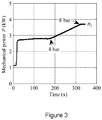
- Figure 3 shows an exemplary identification run at a constant rotational speed.
- the mechanical power of the compressor in a load mode is shown as a function of time.
- the function shows a distinct change in the slope of the curve both when the minimum pressure valve deactivated and when the maximum pressure valve activated.
- the first 60 seconds of measurements were reserved for starting the compressor and ensuring that the compressor unit works at a constant rotational speed and provides constant pressure into the surrounding system. However, depending on the compressor unit, the start-up time may also be shorter or longer.
- the value of the monitored electrical quantity may be directly used as the first and/or the second level.
- the first and/or second level may be calculated from interpolation functions which are based on the limits of the pressure valves and the values of the monitored electrical quantity corresponding to the pressure limits.
- a known mechanical power at a nominal pressure of the compressor may be utilized in determining the first and the second level.
- Information on known mechanical power at a nominal pressure may be available in compressor/pump characteristics provided by the manufacturer, for example. With this information a pressure-power point can be formed. Further, in some embodiments, another pressure-power point may be determined on the basis of the mechanical power at the atmospheric pressure (e.g. when the pressure vessel is empty).
- the operational mode may be initiated.
- the load/unload control scheme is started.
- the compressor is operated at the known rotational speed, and the present value of the at least one electrical quantity is monitored. If the present value falls to the first level, the compressor is set to the load mode. If the present value rises to the second level, the compressor may be set to the unload mode. If the pressure keeps on rising even when the compressor is in the unload mode, the compressor may be shut down.
- the present disclosure also describes a device for implementing a method according to the present disclosure.
- the method may be implemented on an apparatus comprising a computing device, such as a processor, an FPGA (Field-programmable gate array) or an ASIC (Application Specific Integrated Circuit) and a memory, for example.
- the method can be implemented on a frequency converter controlling the electric motor of the compressor, for example. This may be desirable when estimates/measurements of the monitored electrical quantities are readily available from the frequency converter.
Landscapes
- Engineering & Computer Science (AREA)
- Mechanical Engineering (AREA)
- General Engineering & Computer Science (AREA)
- Computer Hardware Design (AREA)
- Physics & Mathematics (AREA)
- Fluid Mechanics (AREA)
- Control Of Positive-Displacement Pumps (AREA)
Claims (8)
- Lade-/Entladesteuerungsverfahren für ein Verdichtersystem, umfassend einen Verdichter, der mit einem Druckbehälter verbunden ist, einem Frequenzwandler, welcher einen Elektromotor des Verdichters steuert, sowie Mittel zum Einstellen des Verdichters entweder auf eine Ladebetriebsart oder eine Entladebetriebsart, wobei das Verfahren eine Identifizierungsphase und eine Betriebsphase umfasst und wobei die Identifizierungsphase umfasst:Betreiben des Verdichters mit einer bekannten Drehzahl des Elektromotors, um den Druck im Innern des Druckbehälters zu erhöhen, während gleichzeitig der Druck und wenigstens eine elektrische Größe des Verdichtersystems überwacht werden,Bestimmen eines ersten Niveaus der wenigstens einen elektrischen Größe basierend auf dem überwachten Druck und der wenigstens einen elektrischen Größe, wobei das erste Niveau einen ersten Druckgrenzwert des Drucks im Innern des Druckbehälters darstellt,Bestimmen eines zweiten Niveaus der wenigstens einen elektrischen Größe basierend auf dem überwachten Druck und der wenigstens einen elektrischen Größe, wobei das zweite Niveau einen zweiten Druckgrenzwert des Drucks im Innern des Druckbehälters darstellt, undSpeichern des ersten Niveaus und des zweiten Niveaus, und wobei die Betriebsphase umfasst:Betreiben des Verdichters mit der bekannten Drehzahl,Überwachen eines gegenwärtigen Wertes der wenigstens einen elektrischen Größe, undfalls der gegenwärtige Wert auf das erste Niveau fällt, Einstellen des Verdichters auf die Ladebetriebsart oder, falls der gegenwärtige Wert auf das zweite Niveau steigt, Einstellen des Verdichters auf die Entladebetriebsart.
- Verfahren gemäß Anspruch 1, wobei die überwachte elektrische Größe gemessen oder geschätzt wird, unter Verwendung des Frequenzwandlers.
- Verfahren gemäß Anspruch 2, wobei die überwachte wenigstens eine elektrische Größe eine Größe ist, die sich auf die mechanische Leistung oder das Drehmoment des Elektromotors bezieht.
- Verfahren gemäß einem der Ansprüche 1 bis 3, wobei das Betreiben des Verdichters in der Identifizierungsphase umfasst:Betreiben des Verdichters in der Ladebetriebsart, um den Druckbehälter mit Druck zu beaufschlagen, um das zweite Niveau zu bestimmen, undBetreiben des Verdichters in der Entladebetriebsart, um den Druck vom Druckbehälter zu nehmen, um das erste Niveau zu bestimmen.
- Verfahren gemäß Anspruch 4, wobei das Bestimmen des zweiten Niveaus erfolgt, wenn der Verdichter in der Ladebetriebsart betrieben wird, und umfasst:Erkennen eines ersten bekannten Drucks im Innern des Druckbehälters und eines ersten Wertes der wenigstens einen elektrischen Größe, der dem ersten bekannten Druck entspricht,Erkennen eines zweiten bekannten Drucks im Innern des Druckbehälters und eines zweiten Wertes der wenigstens einen elektrischen Größe, der dem zweiten bekannten Druck entspricht,Bilden einer Interpolationsfunktion basierend auf dem ersten und dem zweiten bekannten Druck sowie dem ersten und dem zweiten Wert, wobei die Interpolationsfunktion eine Beziehung zwischen dem Druck im Innern des Druckbehälters und der überwachten wenigstens einen elektrischen Größe darstellt, undBestimmen des zweiten Niveaus basierend auf der Interpolationsfunktion und dem zweiten Druckgrenzwert.
- Verfahren gemäß Anspruch 4 oder 5, wobei das Bestimmen des ersten Niveaus erfolgt, wenn der Verdichter in der Entladebetriebsart betrieben wird, und umfasst:Erkennen eines ersten bekannten Drucks im Innern des Druckbehälters und eines ersten Wertes der wenigstens einen elektrischen Größe, der dem ersten bekannten Druck entspricht,Erkennen eines zweiten bekannten Drucks im Innern des Druckbehälters und eines zweiten Wertes der wenigstens einen elektrischen Größe, der dem zweiten bekannten Druck entspricht,Bilden einer Interpolationsfunktion basierend auf dem ersten und dem zweiten bekannten Druck sowie dem ersten und dem zweiten Wert, wobei die Interpolationsfunktion eine Beziehung zwischen dem Druck im Innern des Druckbehälters und der überwachten wenigstens einen elektrischen Größe darstellt, undBestimmen des ersten Niveaus basierend auf der Interpolationsfunktion und dem ersten Druckgrenzwert.
- Vorrichtung, die Mittel zum Implementieren eines Verfahrens gemäß einem der vorstehenden Ansprüche umfasst.
- Vorrichtung gemäß Anspruch 7, wobei die Vorrichtung ein Frequenzwandler ist.
Priority Applications (3)
| Application Number | Priority Date | Filing Date | Title |
|---|---|---|---|
| EP16153122.3A EP3199813B1 (de) | 2016-01-28 | 2016-01-28 | Lade-/entladesteuerungsverfahren für verdichtersystem |
| CN201710061731.0A CN107013443B (zh) | 2016-01-28 | 2017-01-26 | 用于压缩机系统的加载/卸载控制方法及设备 |
| US15/418,326 US10451052B2 (en) | 2016-01-28 | 2017-01-27 | Load/unload control method for compressor system |
Applications Claiming Priority (1)
| Application Number | Priority Date | Filing Date | Title |
|---|---|---|---|
| EP16153122.3A EP3199813B1 (de) | 2016-01-28 | 2016-01-28 | Lade-/entladesteuerungsverfahren für verdichtersystem |
Publications (2)
| Publication Number | Publication Date |
|---|---|
| EP3199813A1 EP3199813A1 (de) | 2017-08-02 |
| EP3199813B1 true EP3199813B1 (de) | 2019-12-04 |
Family
ID=55272280
Family Applications (1)
| Application Number | Title | Priority Date | Filing Date |
|---|---|---|---|
| EP16153122.3A Active EP3199813B1 (de) | 2016-01-28 | 2016-01-28 | Lade-/entladesteuerungsverfahren für verdichtersystem |
Country Status (3)
| Country | Link |
|---|---|
| US (1) | US10451052B2 (de) |
| EP (1) | EP3199813B1 (de) |
| CN (1) | CN107013443B (de) |
Families Citing this family (2)
| Publication number | Priority date | Publication date | Assignee | Title |
|---|---|---|---|---|
| CN114033689B (zh) * | 2021-10-27 | 2023-12-22 | 宁波德曼压缩机有限公司 | 一种变频螺杆空压机空滤堵塞程度的判断方法、系统、智能终端和介质 |
| WO2024213292A1 (de) * | 2023-04-12 | 2024-10-17 | Diehl Ako Stiftung & Co. Kg | Steuersystem für einen kompressor |
Family Cites Families (14)
| Publication number | Priority date | Publication date | Assignee | Title |
|---|---|---|---|---|
| US4586870A (en) * | 1984-05-11 | 1986-05-06 | Elliott Turbomachinery Co., Inc. | Method and apparatus for regulating power consumption while controlling surge in a centrifugal compressor |
| US5713724A (en) * | 1994-11-23 | 1998-02-03 | Coltec Industries Inc. | System and methods for controlling rotary screw compressors |
| JPH094591A (ja) * | 1995-06-19 | 1997-01-07 | Ebara Corp | 容積形流体機械の制御方法及び装置 |
| SE0103371D0 (sv) * | 2001-10-09 | 2001-10-09 | Abb Ab | Flow measurements |
| KR100645808B1 (ko) * | 2004-12-08 | 2006-11-23 | 엘지전자 주식회사 | 모터 제어방법 |
| JP4737770B2 (ja) * | 2006-09-12 | 2011-08-03 | アネスト岩田株式会社 | 真空ポンプの運転制御装置および方法 |
| CN101514698A (zh) * | 2009-02-27 | 2009-08-26 | 南京昱天高新能源科技发展有限公司 | 空压机智能节能控制系统 |
| CN101901014B (zh) * | 2009-05-27 | 2012-02-22 | 宝山钢铁股份有限公司 | 空压站预测调压控制方法 |
| CN201535243U (zh) * | 2009-10-19 | 2010-07-28 | 北京乐普四方方圆科技股份有限公司 | 具有恒压与休眠的空压机节能控制器 |
| JP5224474B2 (ja) * | 2009-12-02 | 2013-07-03 | アネスト岩田株式会社 | 圧縮機の容量制御方法及び圧縮装置 |
| JP5542468B2 (ja) * | 2010-02-10 | 2014-07-09 | 株式会社日立産機システム | 水注入式スクロール空気圧縮機 |
| EP2565465B1 (de) * | 2011-08-29 | 2014-12-10 | ABB Oy | Verfahren und Vorrichtung zur Bestimmung der Massenänderung eines Lüfterrads |
| CN103527461A (zh) * | 2012-07-06 | 2014-01-22 | 博世力士乐(西安)电子传动与控制有限公司 | 空气压缩机的运行控制系统及空气压缩机的运行控制方法 |
| CN203742991U (zh) * | 2014-03-12 | 2014-07-30 | 深圳市新环能科技有限公司 | 一种螺杆式空气压缩机能效提升结构 |
-
2016
- 2016-01-28 EP EP16153122.3A patent/EP3199813B1/de active Active
-
2017
- 2017-01-26 CN CN201710061731.0A patent/CN107013443B/zh active Active
- 2017-01-27 US US15/418,326 patent/US10451052B2/en active Active
Non-Patent Citations (1)
| Title |
|---|
| None * |
Also Published As
| Publication number | Publication date |
|---|---|
| EP3199813A1 (de) | 2017-08-02 |
| US20170218965A1 (en) | 2017-08-03 |
| CN107013443B (zh) | 2019-03-22 |
| US10451052B2 (en) | 2019-10-22 |
| CN107013443A (zh) | 2017-08-04 |
Similar Documents
| Publication | Publication Date | Title |
|---|---|---|
| US10690129B2 (en) | Method and control device for variable rotational speed control of a displacement pump unit and displacement pump arrangement | |
| US11209008B2 (en) | Pump apparatus, test operation method of pump apparatus, motor assembly and method for identifying abnormal vibration of motor assembly | |
| JP5017665B2 (ja) | ポンプ用制御システム | |
| CN103185003B (zh) | 用于最优化泵送系统的能量效率的方法和设备 | |
| US20070160480A1 (en) | No water / dead head detection pump protection algorithm | |
| US20070177985A1 (en) | Integral sensor and control for dry run and flow fault protection of a pump | |
| CN110192036A (zh) | 用于检测泵设备的异常运行状态的方法 | |
| WO2018140905A1 (en) | Motor drive system and method | |
| US20220163043A1 (en) | Pump System Control | |
| EP3256728A1 (de) | Mittel zur erkennung von keinem durchfluss für sensorlose pumpensteuerungsanwendungen | |
| EP3199813B1 (de) | Lade-/entladesteuerungsverfahren für verdichtersystem | |
| CN114396399B (zh) | 用于回转机构的控制方法、控制系统及工程设备 | |
| US11401938B2 (en) | Motor drive system and method | |
| CN107013444B (zh) | 用于压缩机系统的控制方法及设备 | |
| JP2007511703A (ja) | 真空容積式ポンプの駆動モータを制御するための方法 | |
| US10742144B2 (en) | Apparatus and method for controlling a fluid pump for a motor vehicle | |
| EP4001652B1 (de) | Zentrifugalpumpenbetrieb | |
| JP2019011733A (ja) | ポンプ装置及びポンプ装置の制御方法 | |
| JP2018035705A (ja) | 井戸ポンプ装置 | |
| EP3168477A1 (de) | Verfahren und vorrichtung zur schätzung des betriebszustands eines verdrängerkompressors | |
| JP2018100652A (ja) | 井戸ポンプ装置 |
Legal Events
| Date | Code | Title | Description |
|---|---|---|---|
| PUAI | Public reference made under article 153(3) epc to a published international application that has entered the european phase |
Free format text: ORIGINAL CODE: 0009012 |
|
| STAA | Information on the status of an ep patent application or granted ep patent |
Free format text: STATUS: THE APPLICATION HAS BEEN PUBLISHED |
|
| AK | Designated contracting states |
Kind code of ref document: A1 Designated state(s): AL AT BE BG CH CY CZ DE DK EE ES FI FR GB GR HR HU IE IS IT LI LT LU LV MC MK MT NL NO PL PT RO RS SE SI SK SM TR |
|
| AX | Request for extension of the european patent |
Extension state: BA ME |
|
| STAA | Information on the status of an ep patent application or granted ep patent |
Free format text: STATUS: REQUEST FOR EXAMINATION WAS MADE |
|
| 17P | Request for examination filed |
Effective date: 20180131 |
|
| RBV | Designated contracting states (corrected) |
Designated state(s): AL AT BE BG CH CY CZ DE DK EE ES FI FR GB GR HR HU IE IS IT LI LT LU LV MC MK MT NL NO PL PT RO RS SE SI SK SM TR |
|
| STAA | Information on the status of an ep patent application or granted ep patent |
Free format text: STATUS: EXAMINATION IS IN PROGRESS |
|
| 17Q | First examination report despatched |
Effective date: 20180918 |
|
| RAP1 | Party data changed (applicant data changed or rights of an application transferred) |
Owner name: ABB SCHWEIZ AG |
|
| REG | Reference to a national code |
Ref country code: DE Ref legal event code: R079 Ref document number: 602016025339 Country of ref document: DE Free format text: PREVIOUS MAIN CLASS: F04C0028240000 Ipc: F04C0028280000 |
|
| RIC1 | Information provided on ipc code assigned before grant |
Ipc: F04C 28/24 20060101ALI20190410BHEP Ipc: F04C 28/28 20060101AFI20190410BHEP |
|
| GRAP | Despatch of communication of intention to grant a patent |
Free format text: ORIGINAL CODE: EPIDOSNIGR1 |
|
| STAA | Information on the status of an ep patent application or granted ep patent |
Free format text: STATUS: GRANT OF PATENT IS INTENDED |
|
| INTG | Intention to grant announced |
Effective date: 20190703 |
|
| GRAS | Grant fee paid |
Free format text: ORIGINAL CODE: EPIDOSNIGR3 |
|
| GRAA | (expected) grant |
Free format text: ORIGINAL CODE: 0009210 |
|
| STAA | Information on the status of an ep patent application or granted ep patent |
Free format text: STATUS: THE PATENT HAS BEEN GRANTED |
|
| AK | Designated contracting states |
Kind code of ref document: B1 Designated state(s): AL AT BE BG CH CY CZ DE DK EE ES FI FR GB GR HR HU IE IS IT LI LT LU LV MC MK MT NL NO PL PT RO RS SE SI SK SM TR |
|
| REG | Reference to a national code |
Ref country code: GB Ref legal event code: FG4D |
|
| REG | Reference to a national code |
Ref country code: CH Ref legal event code: EP |
|
| REG | Reference to a national code |
Ref country code: AT Ref legal event code: REF Ref document number: 1209747 Country of ref document: AT Kind code of ref document: T Effective date: 20191215 |
|
| REG | Reference to a national code |
Ref country code: DE Ref legal event code: R096 Ref document number: 602016025339 Country of ref document: DE |
|
| REG | Reference to a national code |
Ref country code: IE Ref legal event code: FG4D |
|
| REG | Reference to a national code |
Ref country code: NL Ref legal event code: MP Effective date: 20191204 |
|
| REG | Reference to a national code |
Ref country code: LT Ref legal event code: MG4D |
|
| PG25 | Lapsed in a contracting state [announced via postgrant information from national office to epo] |
Ref country code: LV Free format text: LAPSE BECAUSE OF FAILURE TO SUBMIT A TRANSLATION OF THE DESCRIPTION OR TO PAY THE FEE WITHIN THE PRESCRIBED TIME-LIMIT Effective date: 20191204 Ref country code: SE Free format text: LAPSE BECAUSE OF FAILURE TO SUBMIT A TRANSLATION OF THE DESCRIPTION OR TO PAY THE FEE WITHIN THE PRESCRIBED TIME-LIMIT Effective date: 20191204 Ref country code: BG Free format text: LAPSE BECAUSE OF FAILURE TO SUBMIT A TRANSLATION OF THE DESCRIPTION OR TO PAY THE FEE WITHIN THE PRESCRIBED TIME-LIMIT Effective date: 20200304 Ref country code: NO Free format text: LAPSE BECAUSE OF FAILURE TO SUBMIT A TRANSLATION OF THE DESCRIPTION OR TO PAY THE FEE WITHIN THE PRESCRIBED TIME-LIMIT Effective date: 20200304 Ref country code: FI Free format text: LAPSE BECAUSE OF FAILURE TO SUBMIT A TRANSLATION OF THE DESCRIPTION OR TO PAY THE FEE WITHIN THE PRESCRIBED TIME-LIMIT Effective date: 20191204 Ref country code: GR Free format text: LAPSE BECAUSE OF FAILURE TO SUBMIT A TRANSLATION OF THE DESCRIPTION OR TO PAY THE FEE WITHIN THE PRESCRIBED TIME-LIMIT Effective date: 20200305 Ref country code: LT Free format text: LAPSE BECAUSE OF FAILURE TO SUBMIT A TRANSLATION OF THE DESCRIPTION OR TO PAY THE FEE WITHIN THE PRESCRIBED TIME-LIMIT Effective date: 20191204 |
|
| PG25 | Lapsed in a contracting state [announced via postgrant information from national office to epo] |
Ref country code: HR Free format text: LAPSE BECAUSE OF FAILURE TO SUBMIT A TRANSLATION OF THE DESCRIPTION OR TO PAY THE FEE WITHIN THE PRESCRIBED TIME-LIMIT Effective date: 20191204 Ref country code: RS Free format text: LAPSE BECAUSE OF FAILURE TO SUBMIT A TRANSLATION OF THE DESCRIPTION OR TO PAY THE FEE WITHIN THE PRESCRIBED TIME-LIMIT Effective date: 20191204 |
|
| PG25 | Lapsed in a contracting state [announced via postgrant information from national office to epo] |
Ref country code: AL Free format text: LAPSE BECAUSE OF FAILURE TO SUBMIT A TRANSLATION OF THE DESCRIPTION OR TO PAY THE FEE WITHIN THE PRESCRIBED TIME-LIMIT Effective date: 20191204 |
|
| PG25 | Lapsed in a contracting state [announced via postgrant information from national office to epo] |
Ref country code: RO Free format text: LAPSE BECAUSE OF FAILURE TO SUBMIT A TRANSLATION OF THE DESCRIPTION OR TO PAY THE FEE WITHIN THE PRESCRIBED TIME-LIMIT Effective date: 20191204 Ref country code: CZ Free format text: LAPSE BECAUSE OF FAILURE TO SUBMIT A TRANSLATION OF THE DESCRIPTION OR TO PAY THE FEE WITHIN THE PRESCRIBED TIME-LIMIT Effective date: 20191204 Ref country code: EE Free format text: LAPSE BECAUSE OF FAILURE TO SUBMIT A TRANSLATION OF THE DESCRIPTION OR TO PAY THE FEE WITHIN THE PRESCRIBED TIME-LIMIT Effective date: 20191204 Ref country code: PT Free format text: LAPSE BECAUSE OF FAILURE TO SUBMIT A TRANSLATION OF THE DESCRIPTION OR TO PAY THE FEE WITHIN THE PRESCRIBED TIME-LIMIT Effective date: 20200429 Ref country code: NL Free format text: LAPSE BECAUSE OF FAILURE TO SUBMIT A TRANSLATION OF THE DESCRIPTION OR TO PAY THE FEE WITHIN THE PRESCRIBED TIME-LIMIT Effective date: 20191204 Ref country code: ES Free format text: LAPSE BECAUSE OF FAILURE TO SUBMIT A TRANSLATION OF THE DESCRIPTION OR TO PAY THE FEE WITHIN THE PRESCRIBED TIME-LIMIT Effective date: 20191204 |
|
| PG25 | Lapsed in a contracting state [announced via postgrant information from national office to epo] |
Ref country code: SM Free format text: LAPSE BECAUSE OF FAILURE TO SUBMIT A TRANSLATION OF THE DESCRIPTION OR TO PAY THE FEE WITHIN THE PRESCRIBED TIME-LIMIT Effective date: 20191204 Ref country code: SK Free format text: LAPSE BECAUSE OF FAILURE TO SUBMIT A TRANSLATION OF THE DESCRIPTION OR TO PAY THE FEE WITHIN THE PRESCRIBED TIME-LIMIT Effective date: 20191204 Ref country code: IS Free format text: LAPSE BECAUSE OF FAILURE TO SUBMIT A TRANSLATION OF THE DESCRIPTION OR TO PAY THE FEE WITHIN THE PRESCRIBED TIME-LIMIT Effective date: 20200404 |
|
| REG | Reference to a national code |
Ref country code: CH Ref legal event code: PL |
|
| REG | Reference to a national code |
Ref country code: DE Ref legal event code: R097 Ref document number: 602016025339 Country of ref document: DE |
|
| REG | Reference to a national code |
Ref country code: AT Ref legal event code: MK05 Ref document number: 1209747 Country of ref document: AT Kind code of ref document: T Effective date: 20191204 |
|
| PG25 | Lapsed in a contracting state [announced via postgrant information from national office to epo] |
Ref country code: MC Free format text: LAPSE BECAUSE OF FAILURE TO SUBMIT A TRANSLATION OF THE DESCRIPTION OR TO PAY THE FEE WITHIN THE PRESCRIBED TIME-LIMIT Effective date: 20191204 |
|
| PLBE | No opposition filed within time limit |
Free format text: ORIGINAL CODE: 0009261 |
|
| STAA | Information on the status of an ep patent application or granted ep patent |
Free format text: STATUS: NO OPPOSITION FILED WITHIN TIME LIMIT |
|
| REG | Reference to a national code |
Ref country code: BE Ref legal event code: MM Effective date: 20200131 |
|
| PG25 | Lapsed in a contracting state [announced via postgrant information from national office to epo] |
Ref country code: DK Free format text: LAPSE BECAUSE OF FAILURE TO SUBMIT A TRANSLATION OF THE DESCRIPTION OR TO PAY THE FEE WITHIN THE PRESCRIBED TIME-LIMIT Effective date: 20191204 Ref country code: LU Free format text: LAPSE BECAUSE OF NON-PAYMENT OF DUE FEES Effective date: 20200128 |
|
| 26N | No opposition filed |
Effective date: 20200907 |
|
| PG25 | Lapsed in a contracting state [announced via postgrant information from national office to epo] |
Ref country code: SI Free format text: LAPSE BECAUSE OF FAILURE TO SUBMIT A TRANSLATION OF THE DESCRIPTION OR TO PAY THE FEE WITHIN THE PRESCRIBED TIME-LIMIT Effective date: 20191204 Ref country code: LI Free format text: LAPSE BECAUSE OF NON-PAYMENT OF DUE FEES Effective date: 20200131 Ref country code: PL Free format text: LAPSE BECAUSE OF FAILURE TO SUBMIT A TRANSLATION OF THE DESCRIPTION OR TO PAY THE FEE WITHIN THE PRESCRIBED TIME-LIMIT Effective date: 20191204 Ref country code: CH Free format text: LAPSE BECAUSE OF NON-PAYMENT OF DUE FEES Effective date: 20200131 Ref country code: AT Free format text: LAPSE BECAUSE OF FAILURE TO SUBMIT A TRANSLATION OF THE DESCRIPTION OR TO PAY THE FEE WITHIN THE PRESCRIBED TIME-LIMIT Effective date: 20191204 Ref country code: BE Free format text: LAPSE BECAUSE OF NON-PAYMENT OF DUE FEES Effective date: 20200131 |
|
| PG25 | Lapsed in a contracting state [announced via postgrant information from national office to epo] |
Ref country code: IT Free format text: LAPSE BECAUSE OF FAILURE TO SUBMIT A TRANSLATION OF THE DESCRIPTION OR TO PAY THE FEE WITHIN THE PRESCRIBED TIME-LIMIT Effective date: 20191204 Ref country code: IE Free format text: LAPSE BECAUSE OF NON-PAYMENT OF DUE FEES Effective date: 20200128 |
|
| PG25 | Lapsed in a contracting state [announced via postgrant information from national office to epo] |
Ref country code: TR Free format text: LAPSE BECAUSE OF FAILURE TO SUBMIT A TRANSLATION OF THE DESCRIPTION OR TO PAY THE FEE WITHIN THE PRESCRIBED TIME-LIMIT Effective date: 20191204 Ref country code: MT Free format text: LAPSE BECAUSE OF FAILURE TO SUBMIT A TRANSLATION OF THE DESCRIPTION OR TO PAY THE FEE WITHIN THE PRESCRIBED TIME-LIMIT Effective date: 20191204 Ref country code: CY Free format text: LAPSE BECAUSE OF FAILURE TO SUBMIT A TRANSLATION OF THE DESCRIPTION OR TO PAY THE FEE WITHIN THE PRESCRIBED TIME-LIMIT Effective date: 20191204 |
|
| PG25 | Lapsed in a contracting state [announced via postgrant information from national office to epo] |
Ref country code: MK Free format text: LAPSE BECAUSE OF FAILURE TO SUBMIT A TRANSLATION OF THE DESCRIPTION OR TO PAY THE FEE WITHIN THE PRESCRIBED TIME-LIMIT Effective date: 20191204 |
|
| PGFP | Annual fee paid to national office [announced via postgrant information from national office to epo] |
Ref country code: GB Payment date: 20260123 Year of fee payment: 11 |
|
| PGFP | Annual fee paid to national office [announced via postgrant information from national office to epo] |
Ref country code: DE Payment date: 20260121 Year of fee payment: 11 |
|
| PGFP | Annual fee paid to national office [announced via postgrant information from national office to epo] |
Ref country code: FR Payment date: 20260123 Year of fee payment: 11 |