EP3199828A1 - Fixation de garniture de frein à disque de véhicule et serre-flan pour la fixation des garnitures de frein - Google Patents
Fixation de garniture de frein à disque de véhicule et serre-flan pour la fixation des garnitures de frein Download PDFInfo
- Publication number
- EP3199828A1 EP3199828A1 EP17150154.7A EP17150154A EP3199828A1 EP 3199828 A1 EP3199828 A1 EP 3199828A1 EP 17150154 A EP17150154 A EP 17150154A EP 3199828 A1 EP3199828 A1 EP 3199828A1
- Authority
- EP
- European Patent Office
- Prior art keywords
- brake
- hold
- tube
- down device
- opening
- Prior art date
- Legal status (The legal status is an assumption and is not a legal conclusion. Google has not performed a legal analysis and makes no representation as to the accuracy of the status listed.)
- Granted
Links
Images


Classifications
-
- F—MECHANICAL ENGINEERING; LIGHTING; HEATING; WEAPONS; BLASTING
- F16—ENGINEERING ELEMENTS AND UNITS; GENERAL MEASURES FOR PRODUCING AND MAINTAINING EFFECTIVE FUNCTIONING OF MACHINES OR INSTALLATIONS; THERMAL INSULATION IN GENERAL
- F16D—COUPLINGS FOR TRANSMITTING ROTATION; CLUTCHES; BRAKES
- F16D65/00—Parts or details
- F16D65/02—Braking members; Mounting thereof
- F16D65/04—Bands, shoes or pads; Pivots or supporting members therefor
- F16D65/092—Bands, shoes or pads; Pivots or supporting members therefor for axially-engaging brakes, e.g. disc brakes
- F16D65/095—Pivots or supporting members therefor
- F16D65/097—Resilient means interposed between pads and supporting members or other brake parts
- F16D65/0973—Resilient means interposed between pads and supporting members or other brake parts not subjected to brake forces
- F16D65/0974—Resilient means interposed between pads and supporting members or other brake parts not subjected to brake forces acting on or in the vicinity of the pad rim in a direction substantially transverse to the brake disc axis
- F16D65/0977—Springs made from sheet metal
- F16D65/0978—Springs made from sheet metal acting on one pad only
-
- F—MECHANICAL ENGINEERING; LIGHTING; HEATING; WEAPONS; BLASTING
- F16—ENGINEERING ELEMENTS AND UNITS; GENERAL MEASURES FOR PRODUCING AND MAINTAINING EFFECTIVE FUNCTIONING OF MACHINES OR INSTALLATIONS; THERMAL INSULATION IN GENERAL
- F16D—COUPLINGS FOR TRANSMITTING ROTATION; CLUTCHES; BRAKES
- F16D2250/00—Manufacturing; Assembly
- F16D2250/0084—Assembly or disassembly
Definitions
- the invention relates to a brake pad holder of a vehicle disc brake according to the preamble of patent claim 1 and to a hold-down device for the attachment of brake pads in a disc brake according to the preamble of patent claim 10.
- the invention has for its object to further develop a brake pad holder of a disc brake so that the parts required for this purpose are inexpensive to produce and the assembly and disassembly of the brake pads can simply vonstatten addition. Furthermore, a suitable for such a brake pad holder down device to be created.
- the hold-down is provided in one of its two end portions with a completely or almost completely closed mounting opening extending in the direction of the width of the blank holder and thus in the brake disc circumferential direction.
- a bolt can be pushed, which connects the hold-down with the caliper, which is also the Bolt in the width of the blank holder and thus extends in the brake disc circumferential direction.
- the attachment opening which may be formed in one or two parts, preferably has a round opening cross-section.
- Disc brakes are, for a space-saving arrangement, usually arranged as far as possible outside the vehicle. As a result, parts of the disc brake are already inside the braked vehicle wheel. At the same time, it is desirable to dimension the brake disc of the disc brake as large as possible for a high braking power. However, this endeavor has the consequence that only a small amount of free space remains between the components of the disc brake and the vehicle wheel rotating around the brake. It is not uncommon, therefore, that when additional bending loads occur, there is a grinding of radially outwardly extending brake parts on the rotating inner surface of the vehicle wheel.
- the attachment opening is formed according to a first variant by an eyelet, which consists of a deformed by at least 300 ° material portion of the hold-down. If the hold-down is made of sheet metal, the eyelet is preferably made of a deformed by nearly 360 ° portion of the metal sheet metal, wherein the remainder remaining gap is metallically sealed, preferably by a welding or soldering point.
- a two-part design of the attachment opening consisting of a first attachment opening z. B. in the form of an eyelet, one aligned with the first mounting opening, second mounting opening z. B. in the form of an eyelet, and a space arranged therebetween, into which a molded-on holder of the caliper protrudes.
- both fastening openings are formed by a respective eyelet.
- the attachment opening is formed by a tube which is part of the hold-down and whose tube axis extends in the brake disc circumferential direction.
- this is formed over a large part of its overall length as a groove of an elongated base and arranged on the sides of the base side edges. Only the base is connected to the pipe, whereas the side edges end at a distance from the pipe.
- the tube is firmly bonded to the base, for. B. by welding to the base.
- the tube has a tube length which is greater than the width of the blank holder on the remaining longitudinal extent.
- the drawings show the caliper 1 of a vehicle disc brake for commercial vehicles.
- the disc brake may be of the sliding saddle type or fixed caliper type.
- On each side of the reproduced only on the basis of its axis of rotation A disc brake disc a brake pad 3 is arranged.
- the caliper is provided with a lining shaft 6, over which a bow-shaped lining suppressor 7 extends. This bridges the covering shaft 6 in such a way that the lining retainer 7 extends transversely over both brake linings 3.
- each brake lining 3 consists of the actual friction lining 4 and a back plate 5.
- the back plate 5 serves to better distribute the brake pressure over the lining surface. In addition, it takes over the leadership and the support of the brake pad either on the caliper 1 itself, or on an axle fixed brake carrier of the disc brake.
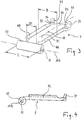
- FIG. 3 and FIG. 4 shown as an item Belagniederhalter 7 is elongated, with its longitudinal center line M extends parallel to the axis of rotation A of the brake disc. Its length in the direction of the axis of rotation A is significantly greater than its width extending in the brake disk circumferential direction B.
- the reproduced on the right, vehicle inner end of the hold-7 is attached directly to the caliper 1, for which purpose this end is seated in a slot-shaped recess 14 of the caliper 1.
- the left reproduced, vehicle outer end of the blank holder 7 is indirectly attached using a bolt 13 to the caliper 1, which will be explained in more detail.
- the hold-down 7 is according to Fig. 1 combined with two bending-elastic hold-down springs 9.
- the object of the hold-down arrangement designed in this way is to fix both brake linings opposite the lining shaft 6 in such a way that the brake linings are not radially outward, based on the axis of rotation A of the brake disc, can emerge from the lining shaft 6 or fall out.
- the rigid hold-down 7 is on the major part of its overall length of trough-shaped cross-section with a arranged on the longitudinal center line M base 7C, followed along both longitudinal edges of the base 7C side edges 8A, 8B, whereby this central longitudinal portion of the blank holder is reinforced against bending forces.
- the flanks 8A, 8B have the shape of rising bevels.
- the hold-down 7 has an approximately trapezoidal cross section and in particular the cross section of a trapezoidal groove on this largest part of its length.
- the angle at which the side flanks 8A, 8B are arranged to the flat bottom of the channel is between 15 ° and 90 °, in the embodiment about 20 °.
- Each hold-down spring 9 consisting of spring steel 9 extends parallel to the respective back plate 5.
- Each hold-down spring 9 is supported in its center from below against the hold-down 7, while it is supported with their ends on the upper edge 25 of the respective back plate 5. In this way, the hold-down 7 exerts by means of hold-down springs 9, a spring force on the brake pads 3, which acts on the brake pads 3 to the rotation axis A back.
- the hold-7 Near one end of the hold-7 is designed narrower with a width B1, as on its the shape of a groove having longitudinal portion on which the hold-down has the width B.
- the longitudinal section with the smaller width B1 is arranged in extension of the elongate base 7C.
- a tube 10 is fixed transversely to the longitudinal center line M, which extends in the direction of the width B of the hold-down.
- the tube axis of the tube 10 therefore extends in the brake disc circumferential direction.
- the side flanks 8A, 8B preferably end at a distance from the tube 10.
- the cylindrical opening cross-section of the tube 10 forms a fastening opening 11 extending in the direction of the width B.
- the latter receives the cylindrical bolt 13, which connects the hold-down 7 to the caliper 1.
- the center axis MB of the attachment opening 11 is lower, namely below the plane of the base 7C.
- the tube 10 is connected by welding to the base 7C of the blank holder 7.
- the wall thickness of the tube 10 is less than the wall thickness of the steel sheet from which the hold-down 7 is made by punching and forming.
- the hold-down can also be produced as a casting.
- two holders 50 are arranged on the brake caliper 1.
- a holder 50 serve here two integrally formed on the caliper 1 bearing blocks. These each have a bore through which the bolt 13 passes.
- the bolt 13 can not solve in the bolt longitudinal direction from the holders 50 and thus out of the saddle, 13 suitable circlips, cotter pins or the like measures are provided on the bolt.
- the bolt 13 penetrates both the two mutually aligned openings in the bearing blocks 50, as well as on the central axis MB, the mounting opening 11 in the tube 10.
- the tube 10 which has the length L, between the two bearing blocks 50 and is located its one end face on the one bearing block 50, and with its other end face on the other bearing block 50 without play or with little play.
- FIGS. 5 to 7 show an alternative embodiment in which the tube 10 is not formed over its entire length and over its entire circumference as a closed tube, but limited to a central portion with a lateral opening 12 is provided. In this way, the weight fraction of the tube 10 at the hold-down 7, and thus also the weight of the hold 7 can be reduced. In addition, the opening 12 may be helpful to provide space against immediately adjacent surfaces or contours of the saddle 1.
- the hold-down device 7 is designed in such a way that a support of this hold-down end against the caliper 1 results in the circumferential direction.
- the holding-down device 7 is provided at this end with a center section 70 extending on its longitudinal center line M and continuing the base 7C, and with one side section 71 or 72 on each side of the central section 70.
- the side sections 71, 72 are located in the extension of the side flanks 8A, 8B of the hold-down section designed as a groove and, viewed in the longitudinal direction of the hold-down, have an upwardly bent, hook-shaped course towards their ends.
- an inner surface 77 arranged above the plane of the base 7C is formed on each side section 71, 72.
- the two inner surfaces 77 are facing each other so that there is a free space between them.
- the support on the mating surfaces 81 can be made without play, or with a limited in the circumferential direction of the brake disc side play.
- the side portions 71, 72 are separated from the central portion 70 by a longitudinal section 73, 74 which is open only to the respective end of the hold-down separated. Only the central portion 70 protrudes into the slot 14 of the caliper 1, however, the side portions 71, 72 are outside the slot.
- the inner surfaces 77 can be supported in the direction of the width B on the brake caliper 1, the saddle 1 is provided above the slot 14 with corresponding, opposing opposing surfaces 81.
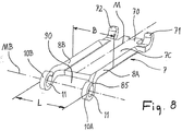
- the Fig. 8 shows a third variant of the hold-down.
- the attachment opening 11 is formed by a total of two eyelets 10A, 10B, wherein each of the two eyelets consists of an approximately 360 ° deformed material portion of the blank holder 7.
- the residual gap 85 remaining as a result of this deformation can be metallically closed for the purpose of reinforcing the eyelet 10A, 10B, preferably by means of a welding or soldering point set in the region of the gap 85.
- the attachment opening 11 consisting of a first attachment opening 11 in the first eye 10A, a second attachment opening 11 in the second eye 10B which is aligned with the first attachment opening, and a free space 90 arranged between the eyes.
- this space 90 of the integrally formed on the caliper 1 serving as a holder bearing block protrudes.
- This bracket can be comparable to the bearing blocks 50 according to the FIGS. 1, 2 . 5 and 6 However, it is only once available and arranged centrally in extension of the longitudinal center line M of the hold-7. He can protrude into the space 90, but the bolt 13 must leave enough space for its installation.
- the length L, measured between the opposite end faces of the two eyelets 10A, 10B is greater than the width B of the blank holder 7 on the remaining longitudinal extent.
Landscapes
- Engineering & Computer Science (AREA)
- General Engineering & Computer Science (AREA)
- Mechanical Engineering (AREA)
- Braking Arrangements (AREA)
Priority Applications (1)
| Application Number | Priority Date | Filing Date | Title |
|---|---|---|---|
| PL17150154T PL3199828T3 (pl) | 2016-01-15 | 2017-01-03 | Zamocowanie okładzin hamulcowych w hamulcu tarczowym w pojeździe oraz dociskacz mocujący okładziny hamulcowe |
Applications Claiming Priority (1)
| Application Number | Priority Date | Filing Date | Title |
|---|---|---|---|
| DE102016100623.8A DE102016100623A1 (de) | 2016-01-15 | 2016-01-15 | Bremsbelaghalterung einer Fahrzeug-Scheibenbremse sowie Niederhalter für die Befestigung von Bremsbelägen |
Publications (2)
| Publication Number | Publication Date |
|---|---|
| EP3199828A1 true EP3199828A1 (fr) | 2017-08-02 |
| EP3199828B1 EP3199828B1 (fr) | 2021-08-25 |
Family
ID=57708518
Family Applications (1)
| Application Number | Title | Priority Date | Filing Date |
|---|---|---|---|
| EP17150154.7A Active EP3199828B1 (fr) | 2016-01-15 | 2017-01-03 | Fixation de garniture de frein à disque de véhicule et serre-flan pour la fixation des garnitures de frein |
Country Status (5)
| Country | Link |
|---|---|
| EP (1) | EP3199828B1 (fr) |
| DE (1) | DE102016100623A1 (fr) |
| DK (1) | DK3199828T3 (fr) |
| ES (1) | ES2889911T3 (fr) |
| PL (1) | PL3199828T3 (fr) |
Cited By (1)
| Publication number | Priority date | Publication date | Assignee | Title |
|---|---|---|---|---|
| IT202100007583A1 (it) | 2021-03-29 | 2022-09-29 | Freni Brembo Spa | Corpo pinza e pinza freno con detto corpo |
Citations (5)
| Publication number | Priority date | Publication date | Assignee | Title |
|---|---|---|---|---|
| DE102005044091A1 (de) | 2005-09-15 | 2007-04-05 | Knorr-Bremse Systeme für Nutzfahrzeuge GmbH | Scheibenbremse, insbesondere für ein Nutzfahrzeug |
| DE102008027052A1 (de) * | 2008-06-06 | 2009-12-24 | Knorr-Bremse Systeme für Nutzfahrzeuge GmbH | Scheibenbremse für ein Nutzfahrzeug |
| DE102009030414A1 (de) * | 2009-06-25 | 2011-01-05 | Knorr-Bremse Systeme für Nutzfahrzeuge GmbH | Bremsbelag für eine Scheibenbremse |
| DE102010043898A1 (de) * | 2010-06-02 | 2011-12-08 | Continental Teves Ag & Co. Ohg | Festsattelbremse und Bremsbelag für eine Festsattelbremse |
| DE102013100162A1 (de) | 2013-01-09 | 2014-07-10 | Knorr-Bremse Systeme für Nutzfahrzeuge GmbH | Scheibenbremse für ein Nutzfahrzeug sowie Bremsbelag für eine Scheibenbremse |
Family Cites Families (4)
| Publication number | Priority date | Publication date | Assignee | Title |
|---|---|---|---|---|
| DE102007041658A1 (de) * | 2006-09-02 | 2008-03-13 | Bpw Bergische Achsen Kg | Fahrzeug-Scheibenbremse |
| DE102013008161A1 (de) * | 2013-05-13 | 2014-11-13 | Wabco Europe Bvba | Sattelscheibenbremse eines Fahrzeugs, insbesondere eines Nutzfahrzeuges, und Bremssattel einer solchen Bremse |
| DE102014019618A1 (de) * | 2014-12-29 | 2016-06-30 | Wabco Europe Bvba | Scheibenbremse |
| DE202015105977U1 (de) * | 2015-11-09 | 2015-11-18 | Knorr-Bremse Systeme für Nutzfahrzeuge GmbH | Scheibenbremse für ein Nutzfahrzeug |
-
2016
- 2016-01-15 DE DE102016100623.8A patent/DE102016100623A1/de active Pending
-
2017
- 2017-01-03 DK DK17150154.7T patent/DK3199828T3/da active
- 2017-01-03 ES ES17150154T patent/ES2889911T3/es active Active
- 2017-01-03 EP EP17150154.7A patent/EP3199828B1/fr active Active
- 2017-01-03 PL PL17150154T patent/PL3199828T3/pl unknown
Patent Citations (5)
| Publication number | Priority date | Publication date | Assignee | Title |
|---|---|---|---|---|
| DE102005044091A1 (de) | 2005-09-15 | 2007-04-05 | Knorr-Bremse Systeme für Nutzfahrzeuge GmbH | Scheibenbremse, insbesondere für ein Nutzfahrzeug |
| DE102008027052A1 (de) * | 2008-06-06 | 2009-12-24 | Knorr-Bremse Systeme für Nutzfahrzeuge GmbH | Scheibenbremse für ein Nutzfahrzeug |
| DE102009030414A1 (de) * | 2009-06-25 | 2011-01-05 | Knorr-Bremse Systeme für Nutzfahrzeuge GmbH | Bremsbelag für eine Scheibenbremse |
| DE102010043898A1 (de) * | 2010-06-02 | 2011-12-08 | Continental Teves Ag & Co. Ohg | Festsattelbremse und Bremsbelag für eine Festsattelbremse |
| DE102013100162A1 (de) | 2013-01-09 | 2014-07-10 | Knorr-Bremse Systeme für Nutzfahrzeuge GmbH | Scheibenbremse für ein Nutzfahrzeug sowie Bremsbelag für eine Scheibenbremse |
Cited By (1)
| Publication number | Priority date | Publication date | Assignee | Title |
|---|---|---|---|---|
| IT202100007583A1 (it) | 2021-03-29 | 2022-09-29 | Freni Brembo Spa | Corpo pinza e pinza freno con detto corpo |
Also Published As
| Publication number | Publication date |
|---|---|
| DK3199828T3 (da) | 2021-09-27 |
| DE102016100623A1 (de) | 2017-07-20 |
| PL3199828T3 (pl) | 2021-12-27 |
| EP3199828B1 (fr) | 2021-08-25 |
| ES2889911T3 (es) | 2022-01-14 |
Similar Documents
| Publication | Publication Date | Title |
|---|---|---|
| EP3359843B1 (fr) | Frein à disque pour véhicule utilitaire | |
| EP2997278B1 (fr) | Frein à disque à étrier d'un véhicule, en particulier d'un véhicule utilitaire, et ressort de retenue d'un tel frein | |
| EP1898115B1 (fr) | Frein à disque de véhicule | |
| EP2997277B1 (fr) | Frein à disque à étrier d'un véhicule, en particulier d'un véhicule utilitaire, et ressort de retenue d'un tel frein | |
| DE102012002734A1 (de) | Belaghaltesystem einer Scheibenbremse eines Kraftfahrzeugs | |
| EP3203102B2 (fr) | Garniture de frein et dispositif de retenue de garniture d'un frein à disque | |
| DE3910154C2 (de) | Blattfederanordnung zum Niederhalten der Bremsbelagträger in einer Scheibenbremse | |
| DE2638508B2 (de) | Führung für den Sattel einer hydraulisch betätigbaren Schwimmsattelteilbelagscheibenbremse für Fahrzeuge | |
| EP3394466B1 (fr) | Garniture de frein à disque et dispositif de retenue pour la fixation de garnitures de frein | |
| EP3612747B1 (fr) | Frein à disque, étrier de frein d'un frein à disque ainsi que serre-flan et ressort à lames pour la fixation de la garniture de frein d'un frein à disque | |
| DE2707058C2 (de) | Schwimmsattelführung für den Schwimmsattel einer Teilbelagscheibenbremse | |
| DE102012108689A1 (de) | Scheibenbremse für ein Fahrzeug | |
| DE4136107A1 (de) | Bremsklotz mit verdrehgesicherter haltefeder | |
| EP4163511A1 (fr) | Support de garniture de frein pour frein à disque de véhicule et garniture de frein pour véhicule | |
| EP1999395A2 (fr) | Support de garniture destiné à des dispositifs de freinage, notamment à des freins à tambour, unité support-garniture de frein et fixation de support de garniture d'un dispositif de compression | |
| EP3199827B1 (fr) | Frein à disque et serre-flan pour la fixation de garnitures de frein dans un frein à disque | |
| WO2017108028A1 (fr) | Plaquette de frein pour un frein à disque, frein à disque et dispositif de retenue pour plaquettes de frein d'un frein à disque | |
| EP3144556A1 (fr) | Dispositif de garniture de frein pour un frein a disque | |
| CH658301A5 (de) | Scheibenbremse, insbesondere fuer fahrzeuge. | |
| DE102015121942A1 (de) | Scheibenbremse für ein Nutzfahrzeug sowie Bremsbelag für eine Scheibenbremse | |
| EP3199828B1 (fr) | Fixation de garniture de frein à disque de véhicule et serre-flan pour la fixation des garnitures de frein | |
| DE1932057B2 (de) | Teilbelagscheibenbremse, insbesondere für Kraftfahrzeuge | |
| EP3368787B1 (fr) | Frein à disque et ressort à lames et support de montage d'un ensemble de pression des plaquettes de frein à disque | |
| DE19652933A1 (de) | Bremsbelag für eine Scheibenbremse | |
| DE102009025875A1 (de) | Vorrichtung zur Erfassung des Reibbelagverschleißes sowie Stab hierfür |
Legal Events
| Date | Code | Title | Description |
|---|---|---|---|
| PUAI | Public reference made under article 153(3) epc to a published international application that has entered the european phase |
Free format text: ORIGINAL CODE: 0009012 |
|
| STAA | Information on the status of an ep patent application or granted ep patent |
Free format text: STATUS: THE APPLICATION HAS BEEN PUBLISHED |
|
| AK | Designated contracting states |
Kind code of ref document: A1 Designated state(s): AL AT BE BG CH CY CZ DE DK EE ES FI FR GB GR HR HU IE IS IT LI LT LU LV MC MK MT NL NO PL PT RO RS SE SI SK SM TR |
|
| AX | Request for extension of the european patent |
Extension state: BA ME |
|
| STAA | Information on the status of an ep patent application or granted ep patent |
Free format text: STATUS: REQUEST FOR EXAMINATION WAS MADE |
|
| 17P | Request for examination filed |
Effective date: 20171212 |
|
| RBV | Designated contracting states (corrected) |
Designated state(s): AL AT BE BG CH CY CZ DE DK EE ES FI FR GB GR HR HU IE IS IT LI LT LU LV MC MK MT NL NO PL PT RO RS SE SI SK SM TR |
|
| STAA | Information on the status of an ep patent application or granted ep patent |
Free format text: STATUS: EXAMINATION IS IN PROGRESS |
|
| 17Q | First examination report despatched |
Effective date: 20201002 |
|
| GRAP | Despatch of communication of intention to grant a patent |
Free format text: ORIGINAL CODE: EPIDOSNIGR1 |
|
| STAA | Information on the status of an ep patent application or granted ep patent |
Free format text: STATUS: GRANT OF PATENT IS INTENDED |
|
| INTG | Intention to grant announced |
Effective date: 20210419 |
|
| GRAS | Grant fee paid |
Free format text: ORIGINAL CODE: EPIDOSNIGR3 |
|
| GRAA | (expected) grant |
Free format text: ORIGINAL CODE: 0009210 |
|
| STAA | Information on the status of an ep patent application or granted ep patent |
Free format text: STATUS: THE PATENT HAS BEEN GRANTED |
|
| AK | Designated contracting states |
Kind code of ref document: B1 Designated state(s): AL AT BE BG CH CY CZ DE DK EE ES FI FR GB GR HR HU IE IS IT LI LT LU LV MC MK MT NL NO PL PT RO RS SE SI SK SM TR |
|
| REG | Reference to a national code |
Ref country code: CH Ref legal event code: EP |
|
| REG | Reference to a national code |
Ref country code: DE Ref legal event code: R096 Ref document number: 502017011261 Country of ref document: DE |
|
| REG | Reference to a national code |
Ref country code: AT Ref legal event code: REF Ref document number: 1424103 Country of ref document: AT Kind code of ref document: T Effective date: 20210915 Ref country code: IE Ref legal event code: FG4D Free format text: LANGUAGE OF EP DOCUMENT: GERMAN |
|
| REG | Reference to a national code |
Ref country code: DK Ref legal event code: T3 Effective date: 20210922 |
|
| REG | Reference to a national code |
Ref country code: GR Ref legal event code: EP Ref document number: 20210402682 Country of ref document: GR Effective date: 20211111 |
|
| REG | Reference to a national code |
Ref country code: LT Ref legal event code: MG9D |
|
| REG | Reference to a national code |
Ref country code: NL Ref legal event code: MP Effective date: 20210825 |
|
| REG | Reference to a national code |
Ref country code: ES Ref legal event code: FG2A Ref document number: 2889911 Country of ref document: ES Kind code of ref document: T3 Effective date: 20220114 |
|
| REG | Reference to a national code |
Ref country code: DE Ref legal event code: R082 Ref document number: 502017011261 Country of ref document: DE Representative=s name: DREISS PATENTANWAELTE PARTG MBB, DE Ref country code: DE Ref legal event code: R082 Ref document number: 502017011261 Country of ref document: DE Representative=s name: JANKE SCHOLL PATENTANWAELTE PARTG MBB, DE |
|
| PG25 | Lapsed in a contracting state [announced via postgrant information from national office to epo] |
Ref country code: LT Free format text: LAPSE BECAUSE OF FAILURE TO SUBMIT A TRANSLATION OF THE DESCRIPTION OR TO PAY THE FEE WITHIN THE PRESCRIBED TIME-LIMIT Effective date: 20210825 Ref country code: BG Free format text: LAPSE BECAUSE OF FAILURE TO SUBMIT A TRANSLATION OF THE DESCRIPTION OR TO PAY THE FEE WITHIN THE PRESCRIBED TIME-LIMIT Effective date: 20211125 Ref country code: NO Free format text: LAPSE BECAUSE OF FAILURE TO SUBMIT A TRANSLATION OF THE DESCRIPTION OR TO PAY THE FEE WITHIN THE PRESCRIBED TIME-LIMIT Effective date: 20211125 Ref country code: PT Free format text: LAPSE BECAUSE OF FAILURE TO SUBMIT A TRANSLATION OF THE DESCRIPTION OR TO PAY THE FEE WITHIN THE PRESCRIBED TIME-LIMIT Effective date: 20211227 Ref country code: FI Free format text: LAPSE BECAUSE OF FAILURE TO SUBMIT A TRANSLATION OF THE DESCRIPTION OR TO PAY THE FEE WITHIN THE PRESCRIBED TIME-LIMIT Effective date: 20210825 Ref country code: HR Free format text: LAPSE BECAUSE OF FAILURE TO SUBMIT A TRANSLATION OF THE DESCRIPTION OR TO PAY THE FEE WITHIN THE PRESCRIBED TIME-LIMIT Effective date: 20210825 Ref country code: SE Free format text: LAPSE BECAUSE OF FAILURE TO SUBMIT A TRANSLATION OF THE DESCRIPTION OR TO PAY THE FEE WITHIN THE PRESCRIBED TIME-LIMIT Effective date: 20210825 Ref country code: RS Free format text: LAPSE BECAUSE OF FAILURE TO SUBMIT A TRANSLATION OF THE DESCRIPTION OR TO PAY THE FEE WITHIN THE PRESCRIBED TIME-LIMIT Effective date: 20210825 |
|
| PG25 | Lapsed in a contracting state [announced via postgrant information from national office to epo] |
Ref country code: LV Free format text: LAPSE BECAUSE OF FAILURE TO SUBMIT A TRANSLATION OF THE DESCRIPTION OR TO PAY THE FEE WITHIN THE PRESCRIBED TIME-LIMIT Effective date: 20210825 |
|
| PG25 | Lapsed in a contracting state [announced via postgrant information from national office to epo] |
Ref country code: NL Free format text: LAPSE BECAUSE OF FAILURE TO SUBMIT A TRANSLATION OF THE DESCRIPTION OR TO PAY THE FEE WITHIN THE PRESCRIBED TIME-LIMIT Effective date: 20210825 |
|
| REG | Reference to a national code |
Ref country code: DE Ref legal event code: R097 Ref document number: 502017011261 Country of ref document: DE |
|
| PG25 | Lapsed in a contracting state [announced via postgrant information from national office to epo] |
Ref country code: SM Free format text: LAPSE BECAUSE OF FAILURE TO SUBMIT A TRANSLATION OF THE DESCRIPTION OR TO PAY THE FEE WITHIN THE PRESCRIBED TIME-LIMIT Effective date: 20210825 Ref country code: SK Free format text: LAPSE BECAUSE OF FAILURE TO SUBMIT A TRANSLATION OF THE DESCRIPTION OR TO PAY THE FEE WITHIN THE PRESCRIBED TIME-LIMIT Effective date: 20210825 Ref country code: RO Free format text: LAPSE BECAUSE OF FAILURE TO SUBMIT A TRANSLATION OF THE DESCRIPTION OR TO PAY THE FEE WITHIN THE PRESCRIBED TIME-LIMIT Effective date: 20210825 Ref country code: EE Free format text: LAPSE BECAUSE OF FAILURE TO SUBMIT A TRANSLATION OF THE DESCRIPTION OR TO PAY THE FEE WITHIN THE PRESCRIBED TIME-LIMIT Effective date: 20210825 Ref country code: CZ Free format text: LAPSE BECAUSE OF FAILURE TO SUBMIT A TRANSLATION OF THE DESCRIPTION OR TO PAY THE FEE WITHIN THE PRESCRIBED TIME-LIMIT Effective date: 20210825 Ref country code: AL Free format text: LAPSE BECAUSE OF FAILURE TO SUBMIT A TRANSLATION OF THE DESCRIPTION OR TO PAY THE FEE WITHIN THE PRESCRIBED TIME-LIMIT Effective date: 20210825 |
|
| PLBE | No opposition filed within time limit |
Free format text: ORIGINAL CODE: 0009261 |
|
| STAA | Information on the status of an ep patent application or granted ep patent |
Free format text: STATUS: NO OPPOSITION FILED WITHIN TIME LIMIT |
|
| REG | Reference to a national code |
Ref country code: DE Ref legal event code: R082 Ref document number: 502017011261 Country of ref document: DE Representative=s name: DREISS PATENTANWAELTE PARTG MBB, DE |
|
| 26N | No opposition filed |
Effective date: 20220527 |
|
| PG25 | Lapsed in a contracting state [announced via postgrant information from national office to epo] |
Ref country code: SI Free format text: LAPSE BECAUSE OF FAILURE TO SUBMIT A TRANSLATION OF THE DESCRIPTION OR TO PAY THE FEE WITHIN THE PRESCRIBED TIME-LIMIT Effective date: 20210825 Ref country code: MC Free format text: LAPSE BECAUSE OF FAILURE TO SUBMIT A TRANSLATION OF THE DESCRIPTION OR TO PAY THE FEE WITHIN THE PRESCRIBED TIME-LIMIT Effective date: 20210825 |
|
| REG | Reference to a national code |
Ref country code: CH Ref legal event code: PL |
|
| PG25 | Lapsed in a contracting state [announced via postgrant information from national office to epo] |
Ref country code: LU Free format text: LAPSE BECAUSE OF NON-PAYMENT OF DUE FEES Effective date: 20220103 |
|
| PG25 | Lapsed in a contracting state [announced via postgrant information from national office to epo] |
Ref country code: LI Free format text: LAPSE BECAUSE OF NON-PAYMENT OF DUE FEES Effective date: 20220131 Ref country code: CH Free format text: LAPSE BECAUSE OF NON-PAYMENT OF DUE FEES Effective date: 20220131 |
|
| PG25 | Lapsed in a contracting state [announced via postgrant information from national office to epo] |
Ref country code: IE Free format text: LAPSE BECAUSE OF NON-PAYMENT OF DUE FEES Effective date: 20220103 |
|
| P01 | Opt-out of the competence of the unified patent court (upc) registered |
Effective date: 20230508 |
|
| PG25 | Lapsed in a contracting state [announced via postgrant information from national office to epo] |
Ref country code: HU Free format text: LAPSE BECAUSE OF FAILURE TO SUBMIT A TRANSLATION OF THE DESCRIPTION OR TO PAY THE FEE WITHIN THE PRESCRIBED TIME-LIMIT; INVALID AB INITIO Effective date: 20170103 |
|
| PG25 | Lapsed in a contracting state [announced via postgrant information from national office to epo] |
Ref country code: MK Free format text: LAPSE BECAUSE OF FAILURE TO SUBMIT A TRANSLATION OF THE DESCRIPTION OR TO PAY THE FEE WITHIN THE PRESCRIBED TIME-LIMIT Effective date: 20210825 Ref country code: CY Free format text: LAPSE BECAUSE OF FAILURE TO SUBMIT A TRANSLATION OF THE DESCRIPTION OR TO PAY THE FEE WITHIN THE PRESCRIBED TIME-LIMIT Effective date: 20210825 |
|
| PG25 | Lapsed in a contracting state [announced via postgrant information from national office to epo] |
Ref country code: MT Free format text: LAPSE BECAUSE OF FAILURE TO SUBMIT A TRANSLATION OF THE DESCRIPTION OR TO PAY THE FEE WITHIN THE PRESCRIBED TIME-LIMIT Effective date: 20210825 |
|
| PGFP | Annual fee paid to national office [announced via postgrant information from national office to epo] |
Ref country code: PL Payment date: 20251203 Year of fee payment: 10 |
|
| PGFP | Annual fee paid to national office [announced via postgrant information from national office to epo] |
Ref country code: GB Payment date: 20260113 Year of fee payment: 10 |
|
| PGFP | Annual fee paid to national office [announced via postgrant information from national office to epo] |
Ref country code: ES Payment date: 20260217 Year of fee payment: 10 |
|
| PGFP | Annual fee paid to national office [announced via postgrant information from national office to epo] |
Ref country code: DE Payment date: 20260323 Year of fee payment: 10 Ref country code: DK Payment date: 20260121 Year of fee payment: 10 |
|
| PGFP | Annual fee paid to national office [announced via postgrant information from national office to epo] |
Ref country code: AT Payment date: 20260119 Year of fee payment: 10 |
|
| PGFP | Annual fee paid to national office [announced via postgrant information from national office to epo] |
Ref country code: BE Payment date: 20260121 Year of fee payment: 10 Ref country code: IT Payment date: 20260130 Year of fee payment: 10 |
|
| PGFP | Annual fee paid to national office [announced via postgrant information from national office to epo] |
Ref country code: FR Payment date: 20260128 Year of fee payment: 10 |
|
| PGFP | Annual fee paid to national office [announced via postgrant information from national office to epo] |
Ref country code: TR Payment date: 20260102 Year of fee payment: 10 |
|
| PGFP | Annual fee paid to national office [announced via postgrant information from national office to epo] |
Ref country code: GR Payment date: 20260119 Year of fee payment: 10 |