EP3199845B1 - Dichtungsstruktur - Google Patents
Dichtungsstruktur Download PDFInfo
- Publication number
- EP3199845B1 EP3199845B1 EP15845454.6A EP15845454A EP3199845B1 EP 3199845 B1 EP3199845 B1 EP 3199845B1 EP 15845454 A EP15845454 A EP 15845454A EP 3199845 B1 EP3199845 B1 EP 3199845B1
- Authority
- EP
- European Patent Office
- Prior art keywords
- backup ring
- pressure side
- high pressure
- peripheral surface
- ring
- Prior art date
- Legal status (The legal status is an assumption and is not a legal conclusion. Google has not performed a legal analysis and makes no representation as to the accuracy of the status listed.)
- Active
Links
Images


Classifications
-
- F—MECHANICAL ENGINEERING; LIGHTING; HEATING; WEAPONS; BLASTING
- F16—ENGINEERING ELEMENTS AND UNITS; GENERAL MEASURES FOR PRODUCING AND MAINTAINING EFFECTIVE FUNCTIONING OF MACHINES OR INSTALLATIONS; THERMAL INSULATION IN GENERAL
- F16J—PISTONS; CYLINDERS; SEALINGS
- F16J15/00—Sealings
- F16J15/16—Sealings between relatively-moving surfaces
- F16J15/18—Sealings between relatively-moving surfaces with stuffing-boxes for elastic or plastic packings
- F16J15/24—Sealings between relatively-moving surfaces with stuffing-boxes for elastic or plastic packings with radially or tangentially compressed packing
-
- F—MECHANICAL ENGINEERING; LIGHTING; HEATING; WEAPONS; BLASTING
- F16—ENGINEERING ELEMENTS AND UNITS; GENERAL MEASURES FOR PRODUCING AND MAINTAINING EFFECTIVE FUNCTIONING OF MACHINES OR INSTALLATIONS; THERMAL INSULATION IN GENERAL
- F16J—PISTONS; CYLINDERS; SEALINGS
- F16J15/00—Sealings
- F16J15/16—Sealings between relatively-moving surfaces
- F16J15/166—Sealings between relatively-moving surfaces with means to prevent the extrusion of the packing
-
- F—MECHANICAL ENGINEERING; LIGHTING; HEATING; WEAPONS; BLASTING
- F16—ENGINEERING ELEMENTS AND UNITS; GENERAL MEASURES FOR PRODUCING AND MAINTAINING EFFECTIVE FUNCTIONING OF MACHINES OR INSTALLATIONS; THERMAL INSULATION IN GENERAL
- F16J—PISTONS; CYLINDERS; SEALINGS
- F16J15/00—Sealings
- F16J15/16—Sealings between relatively-moving surfaces
- F16J15/18—Sealings between relatively-moving surfaces with stuffing-boxes for elastic or plastic packings
-
- F—MECHANICAL ENGINEERING; LIGHTING; HEATING; WEAPONS; BLASTING
- F16—ENGINEERING ELEMENTS AND UNITS; GENERAL MEASURES FOR PRODUCING AND MAINTAINING EFFECTIVE FUNCTIONING OF MACHINES OR INSTALLATIONS; THERMAL INSULATION IN GENERAL
- F16J—PISTONS; CYLINDERS; SEALINGS
- F16J15/00—Sealings
- F16J15/16—Sealings between relatively-moving surfaces
- F16J15/32—Sealings between relatively-moving surfaces with elastic sealings, e.g. O-rings
- F16J15/3268—Mounting of sealing rings
- F16J15/3272—Mounting of sealing rings the rings having a break or opening, e.g. to enable mounting on a shaft otherwise than from a shaft end
-
- F—MECHANICAL ENGINEERING; LIGHTING; HEATING; WEAPONS; BLASTING
- F16—ENGINEERING ELEMENTS AND UNITS; GENERAL MEASURES FOR PRODUCING AND MAINTAINING EFFECTIVE FUNCTIONING OF MACHINES OR INSTALLATIONS; THERMAL INSULATION IN GENERAL
- F16J—PISTONS; CYLINDERS; SEALINGS
- F16J15/00—Sealings
- F16J15/16—Sealings between relatively-moving surfaces
- F16J15/32—Sealings between relatively-moving surfaces with elastic sealings, e.g. O-rings
- F16J15/3284—Sealings between relatively-moving surfaces with elastic sealings, e.g. O-rings characterised by their structure; Selection of materials
-
- F—MECHANICAL ENGINEERING; LIGHTING; HEATING; WEAPONS; BLASTING
- F16—ENGINEERING ELEMENTS AND UNITS; GENERAL MEASURES FOR PRODUCING AND MAINTAINING EFFECTIVE FUNCTIONING OF MACHINES OR INSTALLATIONS; THERMAL INSULATION IN GENERAL
- F16J—PISTONS; CYLINDERS; SEALINGS
- F16J15/00—Sealings
- F16J15/16—Sealings between relatively-moving surfaces
- F16J15/34—Sealings between relatively-moving surfaces with slip-ring pressed against a more or less radial face on one member
- F16J15/3404—Sealings between relatively-moving surfaces with slip-ring pressed against a more or less radial face on one member and characterised by parts or details relating to lubrication, cooling or venting of the seal
- F16J15/3408—Sealings between relatively-moving surfaces with slip-ring pressed against a more or less radial face on one member and characterised by parts or details relating to lubrication, cooling or venting of the seal at least one ring having an uneven slipping surface
- F16J15/3412—Sealings between relatively-moving surfaces with slip-ring pressed against a more or less radial face on one member and characterised by parts or details relating to lubrication, cooling or venting of the seal at least one ring having an uneven slipping surface with cavities
- F16J15/3416—Sealings between relatively-moving surfaces with slip-ring pressed against a more or less radial face on one member and characterised by parts or details relating to lubrication, cooling or venting of the seal at least one ring having an uneven slipping surface with cavities with at least one continuous groove
-
- F—MECHANICAL ENGINEERING; LIGHTING; HEATING; WEAPONS; BLASTING
- F16—ENGINEERING ELEMENTS AND UNITS; GENERAL MEASURES FOR PRODUCING AND MAINTAINING EFFECTIVE FUNCTIONING OF MACHINES OR INSTALLATIONS; THERMAL INSULATION IN GENERAL
- F16J—PISTONS; CYLINDERS; SEALINGS
- F16J15/00—Sealings
- F16J15/002—Sealings comprising at least two sealings in succession
- F16J15/008—Sealings comprising at least two sealings in succession with provision to put out of action at least one sealing; One sealing sealing only on standstill; Emergency or servicing sealings
Definitions
- the present invention relates to a sealing structure including a backup ring.
- a sealing structure which includes a resin backup ring provided adjacently to a seal ring formed of a rubber-like elastic body and at a position further toward a lower pressure side than the seal ring.
- the backup ring allows suppression of stick-out of a part of the seal ring from an annular groove in which the seal ring is installed. Consequently, possible damage to the seal ring can be suppressed.
- a cut portion is formed in the backup ring at one position in a circumferential direction so as to facilitate installation. Thus, a part of the seal ring may be sandwiched between cut surfaces of the cut portion, leading to damage to the seal ring. Therefore, the seal ring still has room for improvement.
- EP 3 118 493 A1 discloses a sealing device capable of preventing the formation of a gap causing biting of a seal member between a backup ring and a shaft under high pressure by means of the backup ring having an L-shaped cross section.
- JP-H 11 315925 A discloses a sealing device capable of following-up eccentricity well and maintaining good sealing performance.
- Another prior art document is FR 2 009 066 A .
- An object of the present invention is to provide a sealing structure that can suppress possible damage to a seal ring because of a backup ring.
- the present invention adopts the following means to solve the above-described problem.
- the present invention provides a sealing structure including:
- the annular edge portion on the high pressure side of the inner peripheral surface of the backup ring is configured to be slidable with respect to the tapered surface formed on the groove bottom surface of the annular groove. Consequently, (substantial) line contact is enabled in the slidable portion, and thus, the backup ring can move smoothly in the direction of the central axis. This suppresses formation of a gap between the backup ring and the annular groove, and thus prevents a part of the seal ring from sticking out between the backup ring and the annular groove.
- the cut portion is formed in the backup ring at one position in the circumferential direction, an operation of installing the backup ring in the annular groove is easy. Furthermore, since the cut portion is shaped like a flat surface by cutting, an operation of forming the cut portion is also easy. In other words, the cut portion can be formed by one cutting operation using a general cutting edge.
- the acute angle of the angles between the surface on the high pressure side of the backup ring and the cutting surface is set to not less than 15° and not more than 30°. Consequently, when the seal ring is pressed toward the backup ring, with the cut surfaces at the cutting portion being separated from each other, a tip portion of the backup ring forming the acute angle in the cutting portion is deflected toward the low pressure side. This enables to prevent a part of the seal ring from being trapped in the gap between the cut surfaces in a sandwiching manner.
- the backup ring is formed of a resin material having Rockwell hardness of 100 or less, durometer hardness of 70 or less, and elastic modulus of 1.0 GPa or less. Consequently, the tip portion of the side of the backup ring forming the acute angle can be easily deflected.
- a surface that is parallel to the central axis and that includes the second cutting line may be positioned radially outward of the annular edge portion on the high pressure side of the inner peripheral surface of the backup ring.
- An outer peripheral surface of the backup ring may be formed of a tapered surface having a diameter decreasing toward the low pressure side.
- the annular edge portion on the high pressure side of the outer peripheral surface of the backup ring may be configured to be slidable with respect to an inner peripheral surface of the shaft hole in the housing.
- a sealing structure is configured such that an annular gap between a shaft and a shaft hole (in a housing) is sealed by a seal ring formed of a rubber-like elastic body.
- the shaft and the housing are concentrically arranged, and these two members may make movement (at least one of rotation and reciprocation) relative to each other or may be stationary. Furthermore, although concentrically arranged, the two members need not necessarily be constantly in a concentric state but may be in an eccentric state. Additionally, in the sealing structure in the present embodiment, one side of the direction of the central axis corresponds to a high pressure side (H), whereas the other side of the direction of the central axis corresponds to a low pressure side (L).
- H high pressure side
- L low pressure side
- a state where no difference in pressure between the opposite sides may occur.
- a sealing target fluid oil or the like
- H high pressure side
- L low pressure side
- the sealing target fluid may be sealed on both sides.
- equipment to which the sealing structure according to the present embodiment is suitably applicable may include an injector unit of a direct injection engine, a cylinder for construction machines, a cylinder for general machinery, and a shock absorber.
- FIG. 4 shows a schematic cross sectional view of the sealing structure according to the embodiment of the present invention, taken along a surface including a central axis of various members.
- the sealing structure according to the present embodiment includes a shaft 300, a housing 400 having a shaft hole 410 through which the shaft 300 is inserted, a seal ring 200 formed of a rubber-like elastic body (for example, NBR) that seals an annular gap between the shaft 300 and the shaft hole 410, and a resin backup ring 100 located adjacently to the seal ring 200.
- An annular groove 310 is formed on an outer peripheral surface of the shaft 300.
- the seal ring 200 and the backup ring 100 are installed in the annular groove 310.
- the seal ring 200 is installed on the high pressure side (H), and backup ring 100 is installed at a position further toward the low pressure side (L) than the seal ring 200.
- a tapered surface 311 having a diameter increasing toward the low pressure side (L) is formed on the low pressure side (L) of a groove bottom surface of the annular groove 310.
- the backup ring 100 is installed at a position where the tapered surface 311 is formed.
- the backup ring 100 serves to prevent stick-out of a part of the seal ring 200 into a gap between an outer peripheral surface of the shaft 300 and an inner peripheral surface of the shaft hole 410 in the housing 400.
- the seal ring 200 according to the present embodiment is an O ring with a circular cross section.
- Fig. 1 is a diagram of the backup ring 100 according to the embodiment of the present invention as viewed from the high pressure side (H).
- Fig. 2 is a diagram of the backup ring 100 according to the embodiment of the present invention as viewed from the low pressure side (L).
- Fig. 3 is a schematic cross sectional diagram of the backup ring 100 according to the embodiment of the present invention. Fig. 3 corresponds to an AA sectional view in Fig. 1 and a BB sectional view in Fig. 2 .
- a surface on the high pressure side (hereinafter referred to as a side surface 130 on the high pressure side) and a surface on the low pressure side (hereinafter referred to as a side surface 140 on the low pressure side) in the backup ring 100 according to the embodiment are both flat surfaces.
- An inner peripheral surface 110 of the backup ring 100 is formed of a tapered surface having a diameter increasing toward the low pressure side (L).
- An outer peripheral surface 120 of the backup ring 100 is formed of a tapered surface having a diameter decreasing toward the low pressure side (L) .
- the taper angle of the inner peripheral surface 110 of the backup ring 100 is set larger than the taper angle of the tapered surface 311 formed on the groove bottom surface of the annular groove 310. Consequently, an annular edge portion 110a on the high pressure side (H) of the inner peripheral surface 110 of the backup ring 100 is slidable with reference to the tapered surface 311 formed on the groove bottom surface (see Fig. 4 ). Therefore, (substantial) line contact is enabled in the slidable portion between the backup ring 100 and the annular groove 310.
- the sealing structure is designed such that a gap is secured between the backup ring 100 and a side surface on the low pressure side of the annular groove 310 even when the backup ring 100 moves closest to the low pressure side (L) in a usage environment (except for an abnormal case). This enables the annular edge portion 110a on the high pressure side (H) of the inner peripheral surface 110 of the backup ring 100 to be kept in (substantial) line contact with the tapered surface 311 of the annular groove 310.
- the outer peripheral surface 120 of the backup ring 100 is formed of a tapered surface having a diameter decreasing toward the low pressure side (L).
- an inner peripheral surface of the shaft hole 410 in the housing 400 is formed of a cylindrical surface. Consequently, the annular edge portion 120a on the high pressure side (H) of the outer peripheral surface 120 of the backup ring 100 is slidable with respect to the inner peripheral surface of the shaft hole 410 in the housing 400 (see Fig. 4 ). Therefore, (substantial) line contact is also enabled in the slidable portion between the backup ring 100 and the shaft hole 410 in the housing 400.
- the angle between the outer peripheral surface 120 and the inner peripheral surface of the shaft hole 410 is designed to be 3° (tolerance of ⁇ 2°) .
- a cut portion 150 is formed by cutting in a flat shape at one position in a circumferential direction.
- the cut portion 150 is formed so that the backup ring 100 can be easily installed in the annular groove 310. So-called "bias cut” is adopted for the cut portion 150 according to the present embodiment.
- a cut surface 153 of the cut portion 150 is a flat surface, and thus, the cut portion 150 can be formed by one cutting operation using a general cutting edge.
- the cut portion 150 according to the present embodiment is configured such that a first cutting line 151 formed on the side surface 130 on the high pressure side of the backup ring 100 is parallel to a second cutting line 152 formed on the side surface 140 on the low pressure side (see Figs. 1 and 2 ).
- the cut portion 150 according to the present embodiment is configured such that the cut surface 153 is oblique to a central axis of the backup ring 100 (see Fig. 3 ).
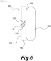
- Fig. 5 and Fig. 6 are diagrams illustrating a relation between the seal ring and the angle of the cut surface of the cut portion formed in the backup ring.
- Fig. 5 and Fig. 6 are diagrams of the seal ring 200 and the backup ring 100 in use as viewed from the outer peripheral surface side.
- Fig. 5 illustrates a case where an acute angle ⁇ 1 of the angles between the side surface 130 on the high pressure side of the backup ring 100 and a cut surface 153a is 45°.
- a tip portion of the backup ring 100 forming the acute angle in the cut portion 150 has a relatively high rigidity.
- a part X of the seal ring 200 is trapped in a gap between the cut surfaces in a sandwiching manner. Consequently, the seal ring 200 may be damaged.
- Fig. 6 illustrates a case where an acute angle ⁇ 2 of the angles between the side surface 130 on the high pressure side of the backup ring 100 and a cut surface 153b is 22°.
- a tip portion of the backup ring 100 forming the acute angle in the cut portion 150 has a relatively low rigidity.
- a tip portion of the backup ring 100 forming the acute angle in the cut portion 150 is deflected toward the low pressure side (L) .
- the tip portion is deflected in the direction of arrow R in Fig. 6 .
- a dotted line illustrates a state where the backup ring 100 is not pressed by the seal ring 200.
- a continuous line illustrates a state where the backup ring 100 is being pressed by the seal ring 200.
- the acute angle ⁇ 2 may suitably be set to 22° (tolerance of ⁇ 5°).
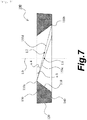
- FIG. 7 is a diagram illustrating a manner of setting the angle of the cut surface 153 of the cut portion 150 formed in the backup ring 100.
- the cut portion 150 is provided such that a line that passes through the center (corresponding to a point L1 in Fig. 7 ) between the first cutting line 151 and the second cutting line 152 and that is parallel to the first cutting line 151 and the second cutting line 152 passes through a central axis L0 of the backup ring 100.
- the distance between the first cutting line 151 and the second cutting line 152 is longest when the cut portion 150 is formed such that the cut surface passes through the annular edge portion 110a on the high pressure side (H) of the inner peripheral surface 110 of the backup ring 100 (see the cut surface 153c in Fig. 7 ).
- An acute angle ⁇ 3 of the angles between the side surface 130 on the high pressure side of the backup ring 100 and the cut surface 153c is smallest. As seen in Fig. 7 , the smaller the bore diameter of the annular edge portion 110a on the high pressure side (H) of the inner peripheral surface 110 of the backup ring 100 is, the larger the acute angle ⁇ 3 needs to be.
- the acute angle of the angles between the side surface 130 on the high pressure side of the backup ring 100 and the cut surface 153c is desirably set to not less than 15° and not more than 30°.
- the acute angle ⁇ 3 may fail to be set to 30° or less.
- the distance between the first cutting line 151 and the second cutting line 152 may be longest when the cut portion 150 is formed such that the cut surface passes both through the annular edge portion 110a on the high pressure side (H) of the inner peripheral surface 110 of the backup ring 100 and through the annular edge portion 110b on the low pressure side (L) of the inner peripheral surface 110 (see a cut surface 153d in Fig. 7 ).
- a line (corresponding to a point L2 in Fig. 7 ) that passes through the center between the first cutting line 151 and the second cutting line 152 and that is parallel to the first cutting line 151 and the second cutting line 152 is separated from the central axis L0 of the backup ring 100.
- This design enables an acute angle ⁇ 4 of the angles between the side surface 130 on the high pressure side of the backup ring 100 and the cut surface 153d can be set smaller.
- a surface 152a (see Fig. 2 ) that is parallel to the central axis L0 and that includes the second cutting line 152 is positioned radially outward of the annular edge portion 110a on the high pressure side (H) of the inner peripheral surface 110 of the backup ring 100.
- the backup ring 100 is formed of a resin material having Rockwell hardness of 100 or less, durometer hardness of 70 or less, and elastic modulus of 1.0 GPa or less.
- a soft resin material such as polyamide may be suitably used.
- the annular edge portion 110a on the high pressure side (H) of the inner peripheral surface 110 of the backup ring 100 is configured to be slidable with respect to the tapered surface 311 formed on the groove bottom surface of the annular groove 310. Since (substantial) line contact is enabled in the slidable portion, the backup ring 100 can move smoothly in the direction of the central axis. This prevents a gap from being formed between the backup ring 100 and the annular groove 310 because the backup ring 100 immediately moves in the direction of the central axis in a case where the difference in pressure between the high pressure side (H) and the low pressure side (L) fluctuates or in a case where the shaft 300 and the housing 400 are eccentric. This suppresses a part of the seal ring 200 from sticking out between the backup ring 100 and the annular groove 310.
- the cut portion 150 is provided in the backup ring 100 at one position in the circumferential direction, an operation of installing the backup ring 100 in the annular groove 310 is easy.
- the cut portion 150 is cut in a planar shape, an operation of forming the cut portion 150 is easy. In other words, the cut portion 150 can be formed by one cutting operation using a general cutting edge.
- the acute angle of the angles between the side surface 130 on the high pressure side of the backup ring 100 and the cut surface 153 is set to not less than 15° and not more than 30°. Consequently, the tip portion of the backup ring 100 forming the acute angle in the cut portion 150 is deflected toward the low pressure side (L) in a case where the seal ring 200 is pressed toward the backup ring 100 while the cut surfaces of the cut portion 150 are separated from each other. This prevents a part of the seal ring 200 from being trapped in the gap between the cut surfaces.
- the backup ring 100 is formed of a resin material having Rockwell hardness of 100 or less, durometer hardness of 70 or less, and elastic modulus of 1.0 GPa or less.
- the tip portion of the backup ring 100 forming the above-described acute angle can be easily deflected. Due to the above mentioned features, trapping of a part of the seal ring 200 in the gap between the cut surfaces can be suppressed effectively.
- the outer peripheral surface of the seal ring 200 was damaged.
- the acute angle of the angles between the cut surface 153 and the side surface 130 on the high pressure side of the backup ring 100 was 22° and Rockwell hardness is 85
- no damage was caused to the outer peripheral surface of the seal ring 200.
- the acute angle of the angles between the cut surface 153 and the side surface 130 on the high pressure side of the backup ring 100 was 22° and durometer hardness is 70, no damage was caused to the outer peripheral surface of the seal ring 200.
- the surface 152a that is parallel to the central axis L0 of the backup ring 100 and that includes the second cutting line 152 can be configured such that the surface 152a is positioned radially outward of the annular edge portion 110a on the high pressure side (H) of the inner peripheral surface 110 of the backup ring 100. Consequently, as described above, even when the bore diameter of the annular edge portion 110a on the high pressure side (H) of the inner peripheral surface 110 of the backup ring 100 is small, the acute angle of the angles between the side surface 130 on the high pressure side of the backup ring 100 and the cut surface 153 can be set small. Consequently, even in a case where the conventional design concept fails to enable the acute angle to be set to not less than 15° and not more than 30°, the above-described configuration allows the acute angle to be set to not less than 15° and not more than 30°.
- the outer peripheral surface 120 of the backup ring 100 is formed of a tapered surface having a diameter decreasing toward the low pressure side (L).
- the annular edge portion 120a on the high pressure side (H) of the outer peripheral surface 120 of the backup ring 100 is configured to be slidable with respect to the inner peripheral surface of the shaft hole 410 in the housing 400. Consequently, in the slidable portion between the shaft hole 410 in the housing 400 and the backup ring 100, (substantial) line contact is enabled. Thus, the backup ring 100 can be moved more smoothly in the direction of the central axis.
Landscapes
- Engineering & Computer Science (AREA)
- General Engineering & Computer Science (AREA)
- Mechanical Engineering (AREA)
- Sealing Devices (AREA)
Claims (3)
- Dichtungsstruktur, mit:einer Welle (300), die mit einer ringförmigen Nut (310) versehen ist, die an einem Außenumfang ausgebildet ist;einem Gehäuse (400) mit einem Wellenloch (410), durch das die Welle (300) eingeführt wird;einem Dichtungsring (200), der aus einem gummiartigen elastischen Körper gebildet ist, der in der ringförmigen Nut (310) eingebaut ist und der einen ringförmigen Spalt zwischen der Welle (300) und dem Wellenloch (410) abdichtet; undeinem Stützring (100) aus Harz, der benachbart zu dem Dichtungsring (200) und an einer Position eingebaut ist, die weiter auf einer Niederdruckseite (L) ist als der Dichtungsring, wobeiauf einer Niederdruckseite (L) einer Nutbodenfläche der ringförmigen Nut (310) eine konische Fläche (311) ausgebildet ist, die einen zur Niederdruckseite (L) hin zunehmenden Durchmesser aufweist,ein Einschnittabschnitt (150), der in einer ebenen Form geschnitten ist, in dem Stützring (100) an einer Position in einer Umfangsrichtung ausgebildet ist, wobei der Einschnittabschnitt (150) konfiguriert ist, so dass eine erste Schnittlinie (151), die auf einer Oberfläche auf einer Hochdruckseite (H) des Stützrings (100) ausgebildet ist, parallel zu einer zweiten Schnittlinie (152) ist, die auf einer Oberfläche auf einer Niederdruckseite (L) des Stützrings (100) ausgebildet ist, und so, dass die Schnittfläche (153) schräg zu einer Mittelachse (L0) des Stützrings (100) ist, und ein spitzer Winkel der Winkel zwischen der Oberfläche auf der Hochdruckseite (H) des Stützrings (100) und der Schnittfläche (153) auf nicht weniger als 15° und nicht mehr als 30° eingestellt ist, undder Stützring (100) aus einem Harzmaterial gebildet ist mit einer Rockwell-Härte von 100 oder weniger, einer Durometer-Härte von 70 oder weniger und einem Elastizitätsmodul von 1,0 GPa oder weniger,wobeieine Innenumfangsfläche (110) des Stützrings (100) von einer konischen Fläche gebildet ist, die einen größeren Konuswinkel hat als die an der Nutbodenfläche gebildete konische Fläche (311) und die einen zur Niederdruckseite (L) hin zunehmenden Durchmesser aufweist, so dass hauptsächlich ein Linienkontakt zwischen einem ringförmigen Kantenabschnitt (110a) auf der Hochdruckseite (H) der Innenumfangsfläche (110) des Stützrings (100) und der ringförmigen Nut (310) ermöglicht wird, und dassder Stützring (100) an einer Position angeordnet ist, an der der ringförmige Kantenabschnitt (110a) auf der Hochdruckseite (H) der Innenumfangsfläche (110) des Stützrings (100) relativ zu der an der Nutbodenfläche ausgebildeten konischen Fläche (311) verschiebbar ist.
- Dichtungsstruktur nach Anspruch 1, wobei eine Fläche, die parallel zur Mittelachse (L0) ist und die die zweite Schnittlinie (152) enthält, radial außerhalb des ringförmigen Kantenabschnitts (110a) auf der Hochdruckseite (H) der Innenumfangsfläche (110) des Stützrings (100) angeordnet ist.
- Dichtungsstruktur nach Anspruch 1 oder 2, wobei eine Außenumfangsfläche (120) des Stützrings (100) aus einer konischen Fläche mit einem zur Niederdruckseite (L) hin abnehmenden Durchmesser gebildet ist, so dass hauptsächlich ein Linienkontakt zwischen einem ringförmigen Kantenabschnitt (120a) auf der Hochdruckseite (H) der Außenumfangsfläche (120) des Stützrings (100) und einer Innenumfangsfläche (110) des Wellenlochs (410) im Gehäuse (400) ermöglicht wird, und der ringförmige Kantenabschnitt (120a) auf der Hochdruckseite (H) der Außenumfangsfläche (120) des Stützrings (100) so konfiguriert ist, dass er relativ zu der Innenumfangsfläche (110) des Wellenlochs (410) im Gehäuse (400) verschiebbar ist.
Applications Claiming Priority (2)
| Application Number | Priority Date | Filing Date | Title |
|---|---|---|---|
| JP2014194418 | 2014-09-24 | ||
| PCT/JP2015/074388 WO2016047369A1 (ja) | 2014-09-24 | 2015-08-28 | 密封構造 |
Publications (3)
| Publication Number | Publication Date |
|---|---|
| EP3199845A1 EP3199845A1 (de) | 2017-08-02 |
| EP3199845A4 EP3199845A4 (de) | 2018-05-09 |
| EP3199845B1 true EP3199845B1 (de) | 2020-07-22 |
Family
ID=55580898
Family Applications (1)
| Application Number | Title | Priority Date | Filing Date |
|---|---|---|---|
| EP15845454.6A Active EP3199845B1 (de) | 2014-09-24 | 2015-08-28 | Dichtungsstruktur |
Country Status (5)
| Country | Link |
|---|---|
| US (1) | US10107401B2 (de) |
| EP (1) | EP3199845B1 (de) |
| JP (2) | JP6128286B2 (de) |
| CN (1) | CN106715982B (de) |
| WO (1) | WO2016047369A1 (de) |
Families Citing this family (9)
| Publication number | Priority date | Publication date | Assignee | Title |
|---|---|---|---|---|
| JP6147946B1 (ja) * | 2015-12-15 | 2017-06-14 | Nok株式会社 | 密封装置 |
| US10520086B2 (en) | 2017-07-11 | 2019-12-31 | T-Lon Products, Inc. | Apparatus and systems for preventing extrusion |
| FR3077859B1 (fr) * | 2018-02-13 | 2020-06-19 | Technic.Com | Ensemble d'etancheite a precharge axiale |
| JP6807891B2 (ja) * | 2018-04-16 | 2021-01-06 | 豊田合成株式会社 | 高圧タンクのシール構造 |
| US11174825B2 (en) | 2019-02-11 | 2021-11-16 | Caterpillar Inc. | Seal configuration for fuel injector |
| CA3147584A1 (en) | 2019-07-16 | 2021-01-21 | James TAUSCH, Jr. | Hammer union |
| CN111486251B (zh) * | 2020-04-20 | 2024-11-22 | 黄新 | 一种高压清洗机用启停开关 |
| EP4163521A4 (de) * | 2020-06-05 | 2024-06-26 | NOK Corporation | Dichtungsstruktur |
| JPWO2023085164A1 (de) * | 2021-11-12 | 2023-05-19 |
Family Cites Families (24)
| Publication number | Priority date | Publication date | Assignee | Title |
|---|---|---|---|---|
| US2616731A (en) * | 1948-06-24 | 1952-11-04 | Dean W Osmun | Packing unit |
| US2809080A (en) * | 1953-11-23 | 1957-10-08 | North American Aviation Inc | Anti-extrusion device for annular seals |
| NL6906856A (de) * | 1968-05-22 | 1969-11-25 | ||
| JPS5733253Y2 (de) * | 1978-07-31 | 1982-07-22 | ||
| JPS5836660U (ja) | 1981-09-02 | 1983-03-10 | エヌオーケー株式会社 | バツクアツプリング |
| US4840379A (en) * | 1988-06-29 | 1989-06-20 | Greene, Tweed & Co. | Split sealing ring having a bias cut |
| US5118119A (en) * | 1991-07-29 | 1992-06-02 | Allied-Signal Inc. | High temperature and high pressure seal retainer ring |
| JPH10184927A (ja) | 1996-12-27 | 1998-07-14 | Mitsubishi Automob Eng Co Ltd | シール装置 |
| JP3543617B2 (ja) * | 1998-04-30 | 2004-07-14 | Nok株式会社 | 密封装置 |
| JP3905239B2 (ja) * | 1999-01-27 | 2007-04-18 | 大日本スクリーン製造株式会社 | 基板保持具および基板処理装置 |
| JP2002161983A (ja) | 2000-11-24 | 2002-06-07 | Nok Corp | 密封装置 |
| JP4337616B2 (ja) * | 2004-04-28 | 2009-09-30 | 信越半導体株式会社 | ウエーハの洗浄装置及びウエーハの洗浄方法 |
| EP1832787B1 (de) * | 2004-12-28 | 2019-02-20 | NOK Corporation | Dichtungsvorrichtung |
| US7793944B2 (en) * | 2004-12-28 | 2010-09-14 | Nok Corporation | Sealing device |
| US7828301B2 (en) * | 2008-01-25 | 2010-11-09 | Intelliserv, Llc | Self-energized backup ring for annular seals |
| US8262091B2 (en) * | 2008-08-29 | 2012-09-11 | Honeywell International Inc. | Scarf cut backup rings |
| JP5359638B2 (ja) * | 2009-07-17 | 2013-12-04 | Nok株式会社 | 密封構造 |
| JP5544616B2 (ja) * | 2009-10-22 | 2014-07-09 | 独立行政法人物質・材料研究機構 | 密封式mas試料管 |
| JP2011220395A (ja) | 2010-04-06 | 2011-11-04 | Nok Corp | バックアップリング |
| JP5513971B2 (ja) * | 2010-05-07 | 2014-06-04 | バンドー化学株式会社 | 自動調心プーリ |
| JP5458076B2 (ja) * | 2011-09-20 | 2014-04-02 | 本田技研工業株式会社 | 封止構造体 |
| KR101723367B1 (ko) * | 2012-09-21 | 2017-04-05 | 엔오케이 가부시키가이샤 | 밀봉장치 |
| JP5547354B1 (ja) * | 2012-10-03 | 2014-07-09 | Nok株式会社 | 密封装置 |
| JP6256117B2 (ja) * | 2014-03-11 | 2018-01-10 | Nok株式会社 | 密封装置 |
-
2015
- 2015-08-28 US US15/511,880 patent/US10107401B2/en active Active
- 2015-08-28 CN CN201580049621.1A patent/CN106715982B/zh active Active
- 2015-08-28 WO PCT/JP2015/074388 patent/WO2016047369A1/ja not_active Ceased
- 2015-08-28 EP EP15845454.6A patent/EP3199845B1/de active Active
- 2015-08-28 JP JP2016550068A patent/JP6128286B2/ja active Active
-
2017
- 2017-02-02 JP JP2017017390A patent/JP2017075703A/ja active Pending
Non-Patent Citations (1)
| Title |
|---|
| None * |
Also Published As
| Publication number | Publication date |
|---|---|
| WO2016047369A1 (ja) | 2016-03-31 |
| CN106715982B (zh) | 2018-05-25 |
| JP6128286B2 (ja) | 2017-05-17 |
| JP2017075703A (ja) | 2017-04-20 |
| US10107401B2 (en) | 2018-10-23 |
| US20170292607A1 (en) | 2017-10-12 |
| CN106715982A (zh) | 2017-05-24 |
| EP3199845A1 (de) | 2017-08-02 |
| JPWO2016047369A1 (ja) | 2017-04-27 |
| EP3199845A4 (de) | 2018-05-09 |
Similar Documents
| Publication | Publication Date | Title |
|---|---|---|
| EP3199845B1 (de) | Dichtungsstruktur | |
| US10520093B1 (en) | Radial shaft seal | |
| US10344865B2 (en) | Sealing device | |
| EP2749796A1 (de) | Dichtungsvorrichtung | |
| US10107121B2 (en) | Carbon seal assembly | |
| CN112955683A (zh) | 密封装置及密封结构 | |
| US20120326396A1 (en) | Sealing system | |
| US20150184753A1 (en) | Mechanical Seal | |
| CA2978105C (en) | Sealing device | |
| JP5359638B2 (ja) | 密封構造 | |
| US11773980B2 (en) | Sealing device | |
| US3420536A (en) | Split ring packing with elastomeric support for rotative and reciprocable parts | |
| JP6001223B1 (ja) | 密封装置 | |
| JP6123945B2 (ja) | 密封構造 | |
| JP2010242814A (ja) | 密封装置 | |
| US20190277406A1 (en) | Mechanical seal | |
| US11835136B2 (en) | Sealing device | |
| US20210102627A1 (en) | Seal structure | |
| JP5195987B2 (ja) | シーリングシステム | |
| JP2014109354A (ja) | 密封装置 | |
| JP2014163459A (ja) | 補強環付きダストシール | |
| WO2010116932A1 (ja) | 密封装置 | |
| JP2008045658A (ja) | 密封装置 | |
| JP2018004027A (ja) | 密封装置 | |
| JP2010249144A (ja) | 密封装置 |
Legal Events
| Date | Code | Title | Description |
|---|---|---|---|
| STAA | Information on the status of an ep patent application or granted ep patent |
Free format text: STATUS: THE INTERNATIONAL PUBLICATION HAS BEEN MADE |
|
| PUAI | Public reference made under article 153(3) epc to a published international application that has entered the european phase |
Free format text: ORIGINAL CODE: 0009012 |
|
| STAA | Information on the status of an ep patent application or granted ep patent |
Free format text: STATUS: REQUEST FOR EXAMINATION WAS MADE |
|
| 17P | Request for examination filed |
Effective date: 20170328 |
|
| AK | Designated contracting states |
Kind code of ref document: A1 Designated state(s): AL AT BE BG CH CY CZ DE DK EE ES FI FR GB GR HR HU IE IS IT LI LT LU LV MC MK MT NL NO PL PT RO RS SE SI SK SM TR |
|
| AX | Request for extension of the european patent |
Extension state: BA ME |
|
| DAV | Request for validation of the european patent (deleted) | ||
| DAX | Request for extension of the european patent (deleted) | ||
| A4 | Supplementary search report drawn up and despatched |
Effective date: 20180409 |
|
| RIC1 | Information provided on ipc code assigned before grant |
Ipc: F16J 15/3284 20160101ALI20180403BHEP Ipc: F16J 15/18 20060101AFI20180403BHEP Ipc: F16J 15/3272 20160101ALI20180403BHEP Ipc: F16J 15/16 20060101ALI20180403BHEP |
|
| GRAP | Despatch of communication of intention to grant a patent |
Free format text: ORIGINAL CODE: EPIDOSNIGR1 |
|
| STAA | Information on the status of an ep patent application or granted ep patent |
Free format text: STATUS: GRANT OF PATENT IS INTENDED |
|
| RIC1 | Information provided on ipc code assigned before grant |
Ipc: F16J 15/18 20060101AFI20200123BHEP Ipc: F16J 15/3284 20160101ALI20200123BHEP Ipc: F16J 15/16 20060101ALI20200123BHEP Ipc: F16J 15/3272 20160101ALI20200123BHEP |
|
| INTG | Intention to grant announced |
Effective date: 20200212 |
|
| GRAS | Grant fee paid |
Free format text: ORIGINAL CODE: EPIDOSNIGR3 |
|
| GRAA | (expected) grant |
Free format text: ORIGINAL CODE: 0009210 |
|
| STAA | Information on the status of an ep patent application or granted ep patent |
Free format text: STATUS: THE PATENT HAS BEEN GRANTED |
|
| AK | Designated contracting states |
Kind code of ref document: B1 Designated state(s): AL AT BE BG CH CY CZ DE DK EE ES FI FR GB GR HR HU IE IS IT LI LT LU LV MC MK MT NL NO PL PT RO RS SE SI SK SM TR |
|
| REG | Reference to a national code |
Ref country code: GB Ref legal event code: FG4D |
|
| REG | Reference to a national code |
Ref country code: CH Ref legal event code: EP |
|
| REG | Reference to a national code |
Ref country code: DE Ref legal event code: R096 Ref document number: 602015056304 Country of ref document: DE |
|
| REG | Reference to a national code |
Ref country code: AT Ref legal event code: REF Ref document number: 1293698 Country of ref document: AT Kind code of ref document: T Effective date: 20200815 |
|
| REG | Reference to a national code |
Ref country code: IE Ref legal event code: FG4D |
|
| REG | Reference to a national code |
Ref country code: LT Ref legal event code: MG4D |
|
| REG | Reference to a national code |
Ref country code: AT Ref legal event code: MK05 Ref document number: 1293698 Country of ref document: AT Kind code of ref document: T Effective date: 20200722 |
|
| PG25 | Lapsed in a contracting state [announced via postgrant information from national office to epo] |
Ref country code: LT Free format text: LAPSE BECAUSE OF FAILURE TO SUBMIT A TRANSLATION OF THE DESCRIPTION OR TO PAY THE FEE WITHIN THE PRESCRIBED TIME-LIMIT Effective date: 20200722 Ref country code: AT Free format text: LAPSE BECAUSE OF FAILURE TO SUBMIT A TRANSLATION OF THE DESCRIPTION OR TO PAY THE FEE WITHIN THE PRESCRIBED TIME-LIMIT Effective date: 20200722 Ref country code: HR Free format text: LAPSE BECAUSE OF FAILURE TO SUBMIT A TRANSLATION OF THE DESCRIPTION OR TO PAY THE FEE WITHIN THE PRESCRIBED TIME-LIMIT Effective date: 20200722 Ref country code: SE Free format text: LAPSE BECAUSE OF FAILURE TO SUBMIT A TRANSLATION OF THE DESCRIPTION OR TO PAY THE FEE WITHIN THE PRESCRIBED TIME-LIMIT Effective date: 20200722 Ref country code: GR Free format text: LAPSE BECAUSE OF FAILURE TO SUBMIT A TRANSLATION OF THE DESCRIPTION OR TO PAY THE FEE WITHIN THE PRESCRIBED TIME-LIMIT Effective date: 20201023 Ref country code: FI Free format text: LAPSE BECAUSE OF FAILURE TO SUBMIT A TRANSLATION OF THE DESCRIPTION OR TO PAY THE FEE WITHIN THE PRESCRIBED TIME-LIMIT Effective date: 20200722 Ref country code: NO Free format text: LAPSE BECAUSE OF FAILURE TO SUBMIT A TRANSLATION OF THE DESCRIPTION OR TO PAY THE FEE WITHIN THE PRESCRIBED TIME-LIMIT Effective date: 20201022 Ref country code: BG Free format text: LAPSE BECAUSE OF FAILURE TO SUBMIT A TRANSLATION OF THE DESCRIPTION OR TO PAY THE FEE WITHIN THE PRESCRIBED TIME-LIMIT Effective date: 20201022 Ref country code: ES Free format text: LAPSE BECAUSE OF FAILURE TO SUBMIT A TRANSLATION OF THE DESCRIPTION OR TO PAY THE FEE WITHIN THE PRESCRIBED TIME-LIMIT Effective date: 20200722 Ref country code: PT Free format text: LAPSE BECAUSE OF FAILURE TO SUBMIT A TRANSLATION OF THE DESCRIPTION OR TO PAY THE FEE WITHIN THE PRESCRIBED TIME-LIMIT Effective date: 20201123 |
|
| PG25 | Lapsed in a contracting state [announced via postgrant information from national office to epo] |
Ref country code: RS Free format text: LAPSE BECAUSE OF FAILURE TO SUBMIT A TRANSLATION OF THE DESCRIPTION OR TO PAY THE FEE WITHIN THE PRESCRIBED TIME-LIMIT Effective date: 20200722 Ref country code: PL Free format text: LAPSE BECAUSE OF FAILURE TO SUBMIT A TRANSLATION OF THE DESCRIPTION OR TO PAY THE FEE WITHIN THE PRESCRIBED TIME-LIMIT Effective date: 20200722 Ref country code: LV Free format text: LAPSE BECAUSE OF FAILURE TO SUBMIT A TRANSLATION OF THE DESCRIPTION OR TO PAY THE FEE WITHIN THE PRESCRIBED TIME-LIMIT Effective date: 20200722 Ref country code: IS Free format text: LAPSE BECAUSE OF FAILURE TO SUBMIT A TRANSLATION OF THE DESCRIPTION OR TO PAY THE FEE WITHIN THE PRESCRIBED TIME-LIMIT Effective date: 20201122 |
|
| PG25 | Lapsed in a contracting state [announced via postgrant information from national office to epo] |
Ref country code: NL Free format text: LAPSE BECAUSE OF FAILURE TO SUBMIT A TRANSLATION OF THE DESCRIPTION OR TO PAY THE FEE WITHIN THE PRESCRIBED TIME-LIMIT Effective date: 20200722 |
|
| REG | Reference to a national code |
Ref country code: CH Ref legal event code: PL |
|
| REG | Reference to a national code |
Ref country code: DE Ref legal event code: R097 Ref document number: 602015056304 Country of ref document: DE |
|
| PG25 | Lapsed in a contracting state [announced via postgrant information from national office to epo] |
Ref country code: CH Free format text: LAPSE BECAUSE OF NON-PAYMENT OF DUE FEES Effective date: 20200831 Ref country code: CZ Free format text: LAPSE BECAUSE OF FAILURE TO SUBMIT A TRANSLATION OF THE DESCRIPTION OR TO PAY THE FEE WITHIN THE PRESCRIBED TIME-LIMIT Effective date: 20200722 Ref country code: DK Free format text: LAPSE BECAUSE OF FAILURE TO SUBMIT A TRANSLATION OF THE DESCRIPTION OR TO PAY THE FEE WITHIN THE PRESCRIBED TIME-LIMIT Effective date: 20200722 Ref country code: IT Free format text: LAPSE BECAUSE OF FAILURE TO SUBMIT A TRANSLATION OF THE DESCRIPTION OR TO PAY THE FEE WITHIN THE PRESCRIBED TIME-LIMIT Effective date: 20200722 Ref country code: LI Free format text: LAPSE BECAUSE OF NON-PAYMENT OF DUE FEES Effective date: 20200831 Ref country code: MC Free format text: LAPSE BECAUSE OF FAILURE TO SUBMIT A TRANSLATION OF THE DESCRIPTION OR TO PAY THE FEE WITHIN THE PRESCRIBED TIME-LIMIT Effective date: 20200722 Ref country code: LU Free format text: LAPSE BECAUSE OF NON-PAYMENT OF DUE FEES Effective date: 20200828 Ref country code: EE Free format text: LAPSE BECAUSE OF FAILURE TO SUBMIT A TRANSLATION OF THE DESCRIPTION OR TO PAY THE FEE WITHIN THE PRESCRIBED TIME-LIMIT Effective date: 20200722 Ref country code: RO Free format text: LAPSE BECAUSE OF FAILURE TO SUBMIT A TRANSLATION OF THE DESCRIPTION OR TO PAY THE FEE WITHIN THE PRESCRIBED TIME-LIMIT Effective date: 20200722 Ref country code: SM Free format text: LAPSE BECAUSE OF FAILURE TO SUBMIT A TRANSLATION OF THE DESCRIPTION OR TO PAY THE FEE WITHIN THE PRESCRIBED TIME-LIMIT Effective date: 20200722 |
|
| REG | Reference to a national code |
Ref country code: BE Ref legal event code: MM Effective date: 20200831 |
|
| PLBE | No opposition filed within time limit |
Free format text: ORIGINAL CODE: 0009261 |
|
| STAA | Information on the status of an ep patent application or granted ep patent |
Free format text: STATUS: NO OPPOSITION FILED WITHIN TIME LIMIT |
|
| PG25 | Lapsed in a contracting state [announced via postgrant information from national office to epo] |
Ref country code: AL Free format text: LAPSE BECAUSE OF FAILURE TO SUBMIT A TRANSLATION OF THE DESCRIPTION OR TO PAY THE FEE WITHIN THE PRESCRIBED TIME-LIMIT Effective date: 20200722 |
|
| 26N | No opposition filed |
Effective date: 20210423 |
|
| PG25 | Lapsed in a contracting state [announced via postgrant information from national office to epo] |
Ref country code: SK Free format text: LAPSE BECAUSE OF FAILURE TO SUBMIT A TRANSLATION OF THE DESCRIPTION OR TO PAY THE FEE WITHIN THE PRESCRIBED TIME-LIMIT Effective date: 20200722 |
|
| PG25 | Lapsed in a contracting state [announced via postgrant information from national office to epo] |
Ref country code: BE Free format text: LAPSE BECAUSE OF NON-PAYMENT OF DUE FEES Effective date: 20200831 Ref country code: SI Free format text: LAPSE BECAUSE OF FAILURE TO SUBMIT A TRANSLATION OF THE DESCRIPTION OR TO PAY THE FEE WITHIN THE PRESCRIBED TIME-LIMIT Effective date: 20200722 Ref country code: IE Free format text: LAPSE BECAUSE OF NON-PAYMENT OF DUE FEES Effective date: 20200828 |
|
| REG | Reference to a national code |
Ref country code: NL Ref legal event code: MP Effective date: 20200722 |
|
| PG25 | Lapsed in a contracting state [announced via postgrant information from national office to epo] |
Ref country code: TR Free format text: LAPSE BECAUSE OF FAILURE TO SUBMIT A TRANSLATION OF THE DESCRIPTION OR TO PAY THE FEE WITHIN THE PRESCRIBED TIME-LIMIT Effective date: 20200722 Ref country code: MT Free format text: LAPSE BECAUSE OF FAILURE TO SUBMIT A TRANSLATION OF THE DESCRIPTION OR TO PAY THE FEE WITHIN THE PRESCRIBED TIME-LIMIT Effective date: 20200722 Ref country code: CY Free format text: LAPSE BECAUSE OF FAILURE TO SUBMIT A TRANSLATION OF THE DESCRIPTION OR TO PAY THE FEE WITHIN THE PRESCRIBED TIME-LIMIT Effective date: 20200722 |
|
| PG25 | Lapsed in a contracting state [announced via postgrant information from national office to epo] |
Ref country code: MK Free format text: LAPSE BECAUSE OF FAILURE TO SUBMIT A TRANSLATION OF THE DESCRIPTION OR TO PAY THE FEE WITHIN THE PRESCRIBED TIME-LIMIT Effective date: 20200722 |
|
| PGFP | Annual fee paid to national office [announced via postgrant information from national office to epo] |
Ref country code: DE Payment date: 20250702 Year of fee payment: 11 |
|
| PGFP | Annual fee paid to national office [announced via postgrant information from national office to epo] |
Ref country code: GB Payment date: 20250703 Year of fee payment: 11 |
|
| PGFP | Annual fee paid to national office [announced via postgrant information from national office to epo] |
Ref country code: FR Payment date: 20250703 Year of fee payment: 11 |