EP3199907A1 - Simulateur pour tir à l'arc - Google Patents
Simulateur pour tir à l'arc Download PDFInfo
- Publication number
- EP3199907A1 EP3199907A1 EP17153471.2A EP17153471A EP3199907A1 EP 3199907 A1 EP3199907 A1 EP 3199907A1 EP 17153471 A EP17153471 A EP 17153471A EP 3199907 A1 EP3199907 A1 EP 3199907A1
- Authority
- EP
- European Patent Office
- Prior art keywords
- target wall
- impact
- projector
- data processing
- projectile
- Prior art date
- Legal status (The legal status is an assumption and is not a legal conclusion. Google has not performed a legal analysis and makes no representation as to the accuracy of the status listed.)
- Granted
Links
- 238000012545 processing Methods 0.000 claims abstract description 31
- 230000005236 sound signal Effects 0.000 claims description 14
- 230000004044 response Effects 0.000 claims description 11
- 239000006260 foam Substances 0.000 claims description 7
- 238000000034 method Methods 0.000 claims description 7
- 230000008569 process Effects 0.000 claims description 7
- 230000004807 localization Effects 0.000 claims description 6
- 238000005259 measurement Methods 0.000 claims description 6
- 238000004458 analytical method Methods 0.000 claims description 5
- 230000009471 action Effects 0.000 claims description 3
- 238000012549 training Methods 0.000 description 21
- 239000000463 material Substances 0.000 description 18
- 230000008901 benefit Effects 0.000 description 13
- 230000005291 magnetic effect Effects 0.000 description 9
- 230000004913 activation Effects 0.000 description 5
- 238000010586 diagram Methods 0.000 description 4
- 238000011156 evaluation Methods 0.000 description 4
- 230000003321 amplification Effects 0.000 description 3
- 230000009849 deactivation Effects 0.000 description 3
- 230000000694 effects Effects 0.000 description 3
- 238000003199 nucleic acid amplification method Methods 0.000 description 3
- 230000003213 activating effect Effects 0.000 description 2
- 230000008859 change Effects 0.000 description 2
- 239000012141 concentrate Substances 0.000 description 2
- 230000005489 elastic deformation Effects 0.000 description 2
- 230000005684 electric field Effects 0.000 description 2
- 230000000737 periodic effect Effects 0.000 description 2
- 238000002360 preparation method Methods 0.000 description 2
- 230000002787 reinforcement Effects 0.000 description 2
- 239000007787 solid Substances 0.000 description 2
- 230000001960 triggered effect Effects 0.000 description 2
- 239000000919 ceramic Substances 0.000 description 1
- 239000013078 crystal Substances 0.000 description 1
- 230000007547 defect Effects 0.000 description 1
- 230000001419 dependent effect Effects 0.000 description 1
- 238000013461 design Methods 0.000 description 1
- 238000001514 detection method Methods 0.000 description 1
- 238000009826 distribution Methods 0.000 description 1
- 239000003302 ferromagnetic material Substances 0.000 description 1
- 238000001914 filtration Methods 0.000 description 1
- 238000010304 firing Methods 0.000 description 1
- 238000009434 installation Methods 0.000 description 1
- 230000003993 interaction Effects 0.000 description 1
- 238000005304 joining Methods 0.000 description 1
- 238000012986 modification Methods 0.000 description 1
- 230000004048 modification Effects 0.000 description 1
- 230000003287 optical effect Effects 0.000 description 1
- 230000010287 polarization Effects 0.000 description 1
- 230000001902 propagating effect Effects 0.000 description 1
- 238000004088 simulation Methods 0.000 description 1
- 238000003860 storage Methods 0.000 description 1
- 230000008685 targeting Effects 0.000 description 1
- 230000000007 visual effect Effects 0.000 description 1
Images


Classifications
-
- F—MECHANICAL ENGINEERING; LIGHTING; HEATING; WEAPONS; BLASTING
- F41—WEAPONS
- F41J—TARGETS; TARGET RANGES; BULLET CATCHERS
- F41J9/00—Moving targets, i.e. moving when fired at
- F41J9/14—Cinematographic targets, e.g. moving-picture targets
-
- F—MECHANICAL ENGINEERING; LIGHTING; HEATING; WEAPONS; BLASTING
- F41—WEAPONS
- F41J—TARGETS; TARGET RANGES; BULLET CATCHERS
- F41J5/00—Target indicating systems; Target-hit or score detecting systems
- F41J5/04—Electric hit-indicating systems; Detecting hits by actuation of electric contacts or switches
- F41J5/056—Switch actuation by hit-generated mechanical vibration of the target body, e.g. using shock or vibration transducers
Definitions
- the present invention relates to a shooting cinematic simulator system, in particular for bow, crossbow and darts sports, including a sensor for detecting projectile impacts on a target wall, which allows shooting under real conditions on moving targets projected onto the target wall.
- One aspect of the invention relates to a system for detecting an impact of a particular mechanically accelerated projectile, which may have a target wall.
- the system may include a projector that may be controlled by a computing device.
- This projector can be configured to display timed targets on the target wall.
- the system according to the invention can comprise at least one impact sensor, which can be arranged on the target wall.
- This impact sensor may also be connected to the data processing unit.
- the data processing unit can, by means of a signal of the impact sensor upon impact of the projectile, cause the projector to stop the passage of the targets that can be displayed on the target wall.
- the system for detecting a projectile impact is designed so that the target wall can be configured such that the projectile can penetrate into the target wall when hitting the target wall and the projectile can be fixed by the material of the target wall.
- the target wall may be configured such that a projectile exceeding a predetermined momentum penetrates the target wall such that the projectile may be enclosed by the material of the target wall and thus held or fixed by the target wall can.
- This embodiment has the advantage that the weft angle of an arrow can be determined simply and directly, since the arrow is fixed in the material of the target wall after the impact in a position corresponding to the weft trajectory.
- the system according to the invention for detecting a projectile impact is designed such that the data processing unit can be a personal computer (PC).
- PC personal computer
- the system for detecting a projectile impact according to the invention is designed so that the target wall can comprise deformable foam.
- This embodiment has the advantage that it makes it possible to use the projectiles (eg arrows) several times without damaging them by an impact on the target wall. This reduces material costs of the shooting training.
- the use of deformable foam on the target wall prevents the projectiles from bouncing off the target wall and becoming indefinably scattered. Thus, the safety during shooting training is increased.
- the system for detecting a projectile impact is designed such that the at least one impact sensor can comprise a piezoelectric element.
- the piezoelectric element can produce a measurable AC voltage as a signal under mechanical action, for example by a time-periodic force.
- the measurable AC voltage can be used as a signal to detect a strike of a projectile on the target wall.
- the AC signal can be used to determine the time of the Geuntereinschlages.
- the system according to the invention for detecting a projectile impact is designed such that the signal of the impact sensor an electronics can be filtered and amplified, in particular the signal can be passed to the input of a sound card of the data processing unit after filtering and amplification.
- the data processing unit's sound card can process the impact sensor signal and, in response, direct control signals to the projector.
- the system for detecting a projectile is designed such that the at least one impact sensor can comprise a reference sound source.
- the reference sound source can emit a sound signal.
- the system for detecting a projectile is designed such that an emission or emission of a sound signal of the reference sound source can be controlled by means of an activation and deactivation of an electromagnet.
- the system for detecting a projectile is designed such that at least four impact sensors can be arranged in edge sections or corner regions of the target wall.
- such a configuration can be used to determine localization information of the impact point of a projectile on the target wall by means of an analysis of measurement signals of the various impact sensors arranged in the edge sections or corner regions of the target wall.
- the system for detecting a projectile is designed so that the various measurement signals of the impact sensors can be obtained and processed by an A / D converter.
- the measurement signals processed by the A / D converter can be routed as digital signals subsequently to a microcontroller (or a microcomputer or a logic unit). This microcontroller can then determine the location information of the impact point of the projectile on the target wall by means of a time analysis of the digitized signals.
- the system for detecting a projectile is designed such that the microcontroller receives the determined or determined localization information of the point of impact of the projectile on the target wall to the data processing unit (PC) can forward.
- the data processing unit (PC) may then control the projector in response to the location information obtained from the microcontroller.
- the system for detecting a projectile is designed so that the projector can stop the time lapse of the targets, which are projected on the target wall by means of the projector or projected onto the target wall.
- the impact location or point of impact of the projectile on the target wall can be optically marked by means of the projector.
- the system for detecting a projectile is arranged such that the projector, controlled by the data processing unit (PC), automatically continues the timeout of the targets displayed on the target wall after a predetermined period of time has elapsed.
- PC data processing unit
- the system for detecting a projectile is designed so that the data processing unit (PC) can be connected to a switching element which can be mechanically actuated or activated.
- the data processing unit (PC) may then, in response to activation of the switching element, cause the projector to continue the timing of the targets displayed on the target wall.
- the video sequence that is projected onto the target wall by means of the project stops immediately (in the millisecond range) after striking a projectile, eg. As an arrow, on the target wall.
- the shooter can thus calmly determine the impact angle of his projectile on the target wall and analyze the past shooting.
- the shooter may seamlessly continue the shooting training process, for example, by activating the switching element (eg, by means of a foot). This increases the efficiency of the shooting training.
- a foot control of the switching element is also allows the shooter can concentrate completely on the guided by his hands firearm, which further increases the quality of the shooting training.
- the shooting system according to the invention thus allows a shooting training under realistic conditions as possible using commercially available components (for example, PC, projector, etc.) for the evaluation of shots. Consequently, a shooting cinematic simulator is provided which significantly improves the efficiency and quality of the shooting training compared to previous systems.
- commercially available components for example, PC, projector, etc.
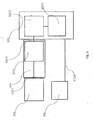
- FIG. 1 a perspective view of an exemplary embodiment of the shooting cinema simulator according to the invention is shown.
- a personal computer (PC) 103 is connected via a connection (cable) 103 B to a projector 102 connected, the PC 103 controls the projector 102.
- the PC 103 is also configured to play video files and to project the contents of these video files to a target wall 100 via the projector 102.
- any video files playable on the PC 103 can be used.
- FIG. 1 shows that the PC 103 is connected to an impact sensor 104 by means of a connection 103 A.
- the connections 103 A, 103 B are designed as data cable connections, but can also be designed optionally as wireless or wireless connections (eg Bluetooth, WLAN, infrared or optical frequency range).
- the impact sensor 104 is physically directly connected to the target wall 100.
- the target wall 100 consists of one or more different deformable foams, wherein the impact sensor 104 is inserted by means of a portion 104 A in the foam of the target wall 100 and is thus brought into direct contact with the target wall 100.
- the portion 104 A of the impact sensor 104 is inserted into the target wall 100, so that the portion 104 A of the impact sensor 104 is enclosed by the material of the target wall 100.
- a positive connection between the portion 104 A of the impact sensor 104 and the material of the target wall 100 is produced.
- density fluctuations 300 in the material of the target wall 100 which are caused by an impact of a projectile 101, are transmitted directly to the portion 104 A of the impact sensor 104.
- the portion 104 A of the impact sensor 104 also includes a piezoelectric element (not shown) that generates a measurable AC voltage under mechanical force, for example, by the mentioned density fluctuations 300.
- the timing with respect to the arrival of the density fluctuations 300 in Impact sensor 104 and generating an AC signal is shown schematically in voltage-time diagram 304 (a detailed discussion will be made in connection with FIG FIG. 2 given).
- the generated alternating voltage signal is also electronically processed and amplified and applied to the input of a sound card of the PC 103.
- the PC 103 (more specifically, software installed on the PC) causes, in response to the obtained AC signal of the impact sensor 104, control of the projector 102, eg, stopping or slowing down the timing of the video sequence projected on the target wall 100.
- FIG. 2 shows a schematic representation of an exemplary embodiment of the shooting cinemas according to the invention or Sch mankinosimulators.
- Impact sensor 104 is physically directly connected to target wall 100 by means of portion 104A.
- the sensor 104 also includes a sound / voltage converter to process acoustic signals.
- the impact sensor 104 comprises a filter and reinforcement element 104 I.
- the filter and reinforcement element 104 I filters and, after the impact of a projectile 101 on the target wall 100, amplifies the AC signal generated by the piezoelectric element (not shown).
- the AC voltage signal is processed by the filter and amplification element 104 I such that it is suitable for the input of a sound card.
- the signal is processed by mechanical and electrical crossovers so that a signal-to-noise ratio is generated, which can be used to detect a projectile impact.
- the thus processed signal is then forwarded by means of the connection 103 A to the PC 103. More specifically, the processed signal is passed to the input of a sound card 103 C of the PC 103.
- the impact millisecond range
- V-time diagram 304 illustrates this relationship schematically.
- the portion 104 A is deflected from its rest position at a later time (t> 0) and thus generates an alternating voltage by means of the piezoelectric element.
- the software 103 D evaluates the AC signal resulting from density fluctuations 300 of the target wall material by the shot impact and controls the playback of the video file in response.
- the software 103D causes the video file timing to be stopped in the millisecond range after impact of the projectile 101 on the target wall 100, ie, the projector 102 is driven and projected by the connection 103B from the PC 103 (more specifically, the software 103D) a time-independent image (still image) on the target wall 100.
- the software 103 D causes a storage of a screenshot and a timestamp of the video for later evaluation of the delivered shot.
- the timing of the video file is automatically continued after a predetermined period of time and projected onto the target wall 100 by means of the projector 102, that is, the timing of the video sequence is continued.
- the projector 102 it is also possible for the projector 102 to continue the timing of the targets displayed on the target wall 100 in response to actuation of a mechanically activatable switching element (eg, wireless footswitch connected to the PC).
- a mechanically activatable switching element eg, wireless footswitch connected to the PC.
- FIG. 3 shows a schematic cross-sectional view of an exemplary embodiment of a weft sensor 104.
- the impact sensor 104 according to the invention comprises a portion 104 A, by means of which the impact sensor 104 can be arranged on the target wall 100 or inserted into the target wall 100.
- the impact sensor 104 includes a piezoelectric element 104 B configured to convert mechanical force (caused, for example, by density fluctuations in the target wall material) into voltage signals. More specifically, in the (direct) piezoelectric effect by means of elastic deformation of a Solid body causes a change in the electrical polarization and consequently generates an electric field (voltage).
- a piezoelectric element is a component which utilizes the piezoelectric effect to generate an electric voltage upon application of a mechanical force to the piezoelectric element.
- Piezoelectric elements may be specific crystals or piezoelectric ceramics (polycrystalline materials).
- electrodes may be applied to the piezoelectric material so that the electric field caused by a mechanical force causes a voltage at the electrodes.
- an AC signal is generated.
- Such a temporally periodic mechanical force is generated, for example, by density fluctuations 300 of the material of the target wall 100, which propagate concentrically from a point of impact of a projectile 101 on impact on the target wall 100.
- a thus generated alternating voltage signal can then be processed or forwarded by the impact sensor.
- the piezoelectric sensor arrangement comprises a seismic mass 104 C.
- a spring 104 D an electromagnet 104 E, and a sound generating element 104 F (clicker), which are arranged separately, ie independently, in a cavity 104 G of the impact sensor 104.
- the cavity 104 G is formed by a shell 104 H.
- the assembly comprising the spring 104 D, the electromagnet 104 E and the clicker 104 F represents a reference sound source of the impact sensor 104.
- the clicker 104 F is connected to the spring 104 D.
- the spring 104 D is also also connected to the solenoid 104 E.
- the solenoid 104 E the spring may be arranged on a section of the casing 104 of the impact sensor 104.
- the Vogeler 104 F consists of or also comprises a ferromagnetic material.
- the clicker 104 F is moved in activation of the electromagnet in the direction of the electromagnet 104 E, whereby the spring 104 D is compressed.
- an activation of the electromagnet 104 E generates a magnetic field which exerts a force on the clicker 104 F and moves the clicker 104 F in the direction of the electromagnet.
- the spring 104 D arranged on the clicker 104 F is compressed or compressed.
- This elastic deformation of the spring 104 D generates a restoring force of the spring 104 D, which is opposite to the direction of movement of the clicker 104 F caused by the electromagnet 104 E (the magnetic field is configured such that the magnetic force generated by the magnetic field is greater than that Restoring force of the spring 104 D). Therefore, with a deactivation of the electromagnet 104 E, in which also the magnetic field is deactivated, the clicker 104 F by the restoring force of the spring 104 D of the electromagnet 104 E is moved away.
- FIGS. 3B and 3C shown schematically.
- the solenoid 104 E is in a deactivated state (FIG. B).
- the clicker 104 F is held by the spring 104 E (more precisely, by a restoring force of the spring 104 E, represented by the arrow in Figure B) at a predetermined distance from the electromagnet 104 E, i. there is initially no direct physical contact between the clicker 104 F and the electromagnet 104 E.
- Activation of the electromagnet 104 E generates a magnetic field.
- the clicker 104 F By the force of the magnetic field (represented by the arrow in Figure C), the clicker 104 F is moved or pulled in the direction of the electromagnet 104 D and the spring 104 E simultaneously compressed or compressed, whereby an increase in the magnetic field opposing spring force is caused , Upon reaching the electromagnet 104 D, the clicker 104 F strikes the electromagnet 104 D. This impact generates a sound signal.
- the reference sound source of the impact sensor 104 may be configured so that when the clicker 104 is moved 104 F is driven to its home position by the spring return force of the spring 104 E, the clicker 104 F is driven against a portion of the shell 104 H of the impact sensor 104, and thus a measurable sound signal is generated.
- the reference sound source is controlled by the PC 103. More specifically, the PC 103 controls the solenoid 104 E by activating and deactivating via a DC signal.
- an impact sensor 104 according to the invention also comprises a filter and amplification element 104 I that filters and amplifies the AC signal so that it is suitable for the input of a sound card.
- FIG. 4 is a perspective view of an exemplary embodiment of a shooting cinema simulator system configured to detect missiles and locate the impact point.
- FIG. 4 shown exemplary Sch mankinosimulatorsystems corresponds essentially to the already explained embodiment with respect to FIG. 1 , For this reason, corresponding elements will not be described again in detail at this point, but it will be to the corresponding embodiments, in particular in relation to the Figures 1-3 , referenced.
- a plurality of impact sensors 104 are arranged on the target wall 100 or fixed to the target wall 100. More specifically, four impact sensors 104 are located at the edge portions of the target wall 100.
- These four impact sensors 104 are each connected to the target wall 100 in the manner described above, and are thus capable of detecting density fluctuations from a projectile 101, which hits the target wall 101.
- the voltage-time diagrams 304 A, B, C, D is shown that, depending on the (Euclidean) distance of the respective Impact sensor 104 to the impact location of a projectile 101 on the target wall 100, at different times an AC voltage signal in the respective impact sensor 104 by the density fluctuations 300 is triggered.
- the impact sensor 104 in the upper left edge region of the target wall 100 is closest to the impact location of the projectile 101, ie it has the lowest Euclidean distance to the impact location of the projectile 101 on the target wall 100.
- the density fluctuations 300 propagating through the material of the target wall 100 reach this impact sensor 104 first in time and trigger a corresponding alternating voltage signal at the impact sensor 104.
- the impact sensor 104 at the lower left edge portion of the target wall 100 has the second lowest Euclidean distance to the impact location of the projectile 101 and is next reached by the density fluctuations 300.
- an AC signal is generated in the impact sensor 104 at a later time than the impact sensor 104 of the left upper edge portion of the target wall 100.
- the impact sensor 104 which is located in the upper right edge region of the target wall 100, has the third lowest Euclidean distance from the impact location of the projectile 101 and is reached by the density fluctuations 300 after the impact sensors 104 located in the left upper and lower left margins of the target wall 100 , Accordingly, an impact voltage is generated at the impact sensor 104 located at the right upper edge portion of the target wall 100 at a timing later than the times of AC generation in the impact sensors 104 of the upper left and left lower edge portions of the target wall 100.
- the impact sensor 104 which is arranged in the lower right edge region of the target wall 100, is achieved by the density fluctuations 300 as the last of the four impact sensors 104.
- the impact sensors 104 are each connected to a PC 103 by means of connections 103 A.
- the PC 103 is configured to control a projector 102 that can project any video sequences onto the target wall 100.
- the AC signals of the impact sensors 104 not transmitted to a sound card of the PC 103, but forwarded to a Mikrocontrol- and analog / digital converter element 200 for further processing (not shown).
- the microcontroller and analog to digital converter element 200 determines the position of the impact of the projectile 101 on the target wall 100 and forwards the determined information to the PC 103 (for a more detailed description of the position determination, see the description of FIG. 5 ).
- the PC 103 causes control of the projector 102 in response to the information obtained. More specifically, the reproduction of the video / video file being played is stopped and the point of impact of the projectile 101 on the target wall 100 is optically marked.
- FIG. 5 FIG. 12 is a schematic illustration of an exemplary embodiment of a shooting cinema simulator system configured to detect missiles and locate the impact point.
- FIG. 5 shows FIG. 5 the target wall 100, which may include a special foam or various foams.
- four impact sensors 104 are shown in the edge regions of the target wall 100, which are each arranged or fastened in an edge region / corner region of the target wall 100.
- the four impact sensors 104 are each connected via a connection 103 A to a microcontroller and analog / digital converter element 200.
- the reference sound sources of the individual impact sensors 104 are used after an arrangement or attachment of the impact sensors 104 on the target wall 100 in order to determine the position of the respective impact sensors 104 in relation to each other.
- the clicker will be 104 F each in turn Impact sensor 104 is activated, whereby each sound signals are emitted.
- These sound signals are respectively acquired or registered and processed by preferably all of the four impact sensors 104 (however, it is also possible to register and process less than four sound signals).
- the received sound signals are converted by the sound / voltage converters of the impact sensors 104 into voltage signals and processed by the microcontroller of the microcontroller and analog / digital converter element 200.
- the microcontroller determines the respective positions of the impact sensors 104 to each other on the target wall 100.
- the positions of the impact sensors 104 on the target wall 100 are calibrated due to the different sound propagation times , the sound signals emitted from the reference sound sources of the impact sensors 104.
- the relative positions of the impact sensors 104 relative to each other on the target wall are determined by the microcontroller.
- the microcontroller can then determine the position of the impact of a projectile 101 on the target wall 100.
- the analog / digital converter interrogates the AC signals of the sensors and, starting from a predetermined measured voltage, forwards a digital 1 signal to the microcontroller.
- These digital 1 signals are thus registered by the microcontroller at (four) different times. These different times correspond to the different times at which the density fluctuations 300 reach the respective impact sensors 104 and generate an AC signal at the respective impact sensor 104.
- the microcontroller From the relative position information of the impact sensors 104 to each other and the different times of registration of the digital 1 signals, the microcontroller calculates the position of the impact of the projectile 101 on the target wall 100. The determined information regarding the impact position is then transmitted by means of a connection (for example a USB connection). Connection) 201 to the PC 103.
- a connection for example a USB connection
- the PC 103 controls the projector 102 in response to the information obtained and causes the timing of the video sequence to be stopped and the impact position of the projectile 101 on the target wall 100 optically, e.g. B. using a crosshair or a target ring assembly (disk mirror), highlighted or marked.
- the present invention provides a shooting cinema simulator with missile strike detection.
- This system is provided by the use of commercially available components (PC, sound card) particularly cost.
- PC commercially available components
- sound card sound card
Landscapes
- Engineering & Computer Science (AREA)
- General Engineering & Computer Science (AREA)
- Aiming, Guidance, Guns With A Light Source, Armor, Camouflage, And Targets (AREA)
Applications Claiming Priority (1)
| Application Number | Priority Date | Filing Date | Title |
|---|---|---|---|
| DE102016201183.9A DE102016201183A1 (de) | 2016-01-27 | 2016-01-27 | Schießkino für den Bogen-, Armbrust-, und Dartsport |
Publications (2)
| Publication Number | Publication Date |
|---|---|
| EP3199907A1 true EP3199907A1 (fr) | 2017-08-02 |
| EP3199907B1 EP3199907B1 (fr) | 2019-01-09 |
Family
ID=57914825
Family Applications (1)
| Application Number | Title | Priority Date | Filing Date |
|---|---|---|---|
| EP17153471.2A Not-in-force EP3199907B1 (fr) | 2016-01-27 | 2017-01-27 | Simulateur pour tir à l'arc |
Country Status (2)
| Country | Link |
|---|---|
| EP (1) | EP3199907B1 (fr) |
| DE (1) | DE102016201183A1 (fr) |
Cited By (1)
| Publication number | Priority date | Publication date | Assignee | Title |
|---|---|---|---|---|
| WO2019030438A1 (fr) * | 2017-08-09 | 2019-02-14 | Commissariat à l'énergie atomique et aux énergies alternatives | Procede de fabrication d'un dispositif de localisation d'impact a au moins trois transducteurs fixes contre une surface interactive |
Citations (5)
| Publication number | Priority date | Publication date | Assignee | Title |
|---|---|---|---|---|
| WO1994003246A1 (fr) * | 1992-08-04 | 1994-02-17 | Dart International, Incorporated | Procede et appareil d'entrainement au tir a l'arc |
| US5649706A (en) * | 1994-09-21 | 1997-07-22 | Treat, Jr.; Erwin C. | Simulator and practice method |
| US20120200041A1 (en) * | 2010-12-06 | 2012-08-09 | Inter-Pac, Inc. | Method of manufacturing archery target |
| US20130193645A1 (en) * | 2011-11-13 | 2013-08-01 | Hex Systems Pty. Ltd. | Projectile target system |
| US20150023591A1 (en) * | 2013-07-18 | 2015-01-22 | Ramakrishna Potluri, Intellecttech Corp Pvt Ltd | Optical analysis of a point of aim of a projectile discharge device |
Family Cites Families (5)
| Publication number | Priority date | Publication date | Assignee | Title |
|---|---|---|---|---|
| DE3447483A1 (de) * | 1984-12-27 | 1986-07-03 | Erich Dr. 8501 Rosstal Neutz | Vorrichtung zur automatischen anzeige der trefferlage metallischer geschosse |
| US5823779A (en) * | 1996-05-02 | 1998-10-20 | Advanced Interactive Systems, Inc. | Electronically controlled weapons range with return fire |
| US20060066053A1 (en) * | 2004-09-28 | 2006-03-30 | Skala Ted P | Game apparatus where darts are thrown into a projected video game image and software conducts the game progress by locating the darts with digital cameras |
| EP2729755A4 (fr) * | 2011-07-07 | 2015-02-25 | Mih Ly Garas | Système de marquage de points pour tir à l'arc |
| JP6139105B2 (ja) * | 2012-11-09 | 2017-05-31 | 株式会社セガゲームス | ダーツゲーム装置 |
-
2016
- 2016-01-27 DE DE102016201183.9A patent/DE102016201183A1/de not_active Withdrawn
-
2017
- 2017-01-27 EP EP17153471.2A patent/EP3199907B1/fr not_active Not-in-force
Patent Citations (5)
| Publication number | Priority date | Publication date | Assignee | Title |
|---|---|---|---|---|
| WO1994003246A1 (fr) * | 1992-08-04 | 1994-02-17 | Dart International, Incorporated | Procede et appareil d'entrainement au tir a l'arc |
| US5649706A (en) * | 1994-09-21 | 1997-07-22 | Treat, Jr.; Erwin C. | Simulator and practice method |
| US20120200041A1 (en) * | 2010-12-06 | 2012-08-09 | Inter-Pac, Inc. | Method of manufacturing archery target |
| US20130193645A1 (en) * | 2011-11-13 | 2013-08-01 | Hex Systems Pty. Ltd. | Projectile target system |
| US20150023591A1 (en) * | 2013-07-18 | 2015-01-22 | Ramakrishna Potluri, Intellecttech Corp Pvt Ltd | Optical analysis of a point of aim of a projectile discharge device |
Cited By (3)
| Publication number | Priority date | Publication date | Assignee | Title |
|---|---|---|---|---|
| WO2019030438A1 (fr) * | 2017-08-09 | 2019-02-14 | Commissariat à l'énergie atomique et aux énergies alternatives | Procede de fabrication d'un dispositif de localisation d'impact a au moins trois transducteurs fixes contre une surface interactive |
| FR3070080A1 (fr) * | 2017-08-09 | 2019-02-15 | Commissariat A L'energie Atomique Et Aux Energies Alternatives | Procede de fabrication d'un dispositif de localisation d'impact a au moins trois transducteurs fixes contre une surface interactive |
| US11231256B2 (en) | 2017-08-09 | 2022-01-25 | Commissariat A L'energie Atomique Et Aux Energies Alternatives | Method for manufacturing a device for locating an impact having at least three transducers attached against an interactive surface |
Also Published As
| Publication number | Publication date |
|---|---|
| DE102016201183A1 (de) | 2017-07-27 |
| EP3199907B1 (fr) | 2019-01-09 |
Similar Documents
| Publication | Publication Date | Title |
|---|---|---|
| DE69332878T2 (de) | Verfahren und vorrichtung zur bestimmung der bahn eines überschallprojektils | |
| DE3411786C2 (fr) | ||
| DE2738213A1 (de) | Einrichtung zur selbsttaetigen elektronischen ermittlung und anzeige der lage von treffern auf einem schiessziel | |
| EP3199907B1 (fr) | Simulateur pour tir à l'arc | |
| DE2952926C2 (de) | Vorrichtung für Zielübungen an Geschützen | |
| DE2429006B2 (de) | Verfahren zur Schußsimulation ferngelenkter Flugkörper und Vorrichtung zur Durchführung des Verfahrens | |
| DE2523362C2 (de) | Elektronischer Schieß-Simulator | |
| EP2881695B1 (fr) | Simulateur d'armes destiné à la simulation de situations critiques pour la sécurité et arme de simulation sous forme d'un projectile destiné à être utilisé dans un simulateur d'armes | |
| EP2689210A1 (fr) | Dispositif pour la réalisation d'une cible virtuelle pour un entraînement pointu au tir | |
| EP3348953A1 (fr) | Dispositif de détermination de la précision de tir d'un tireur | |
| KR200360387Y1 (ko) | 비비탄을 이용한 사격용 타겟장치 | |
| EP1342976A1 (fr) | Champ de tir d'entraînement | |
| DE4413628A1 (de) | Verfahren und Vorrichtung zum Betreiben einer Filmprojectionsvorrichtung, insbesondere in einem Schießkino | |
| DE343504C (fr) | ||
| EP3644008B1 (fr) | Dispositif de visée et procédé de détection d'une position de projectile | |
| DE20001720U1 (de) | Vorrichtung zur Identifikation von Schützen | |
| DE2008986B2 (de) | Gerät zum Simulieren von Fernlenkgeschossen | |
| DE2263217C2 (de) | Trefferanzeigevorrichtung, insbesondere an großflächigen Zielscheiben | |
| DE19729771A1 (de) | Projektionsfläche für den Betrieb eines Schießkinos, sowie Vorrichtung und Verfahren zum Erfassen eines Projektilaufprallpunktes auf einem Körper bzw. einer Projektionsfläche | |
| DE69408079T2 (de) | System zur Lokalisierung von mobilen Objekten | |
| DE2320850B2 (de) | Beweglicher Zielkörper für den Schießsport | |
| DE10234396A1 (de) | Verfahren und Anordnung zum Simulieren von Jagd- und Sportschießen | |
| DE3803839A1 (de) | Abschusseinrichtung fuer modellflugzeuge | |
| CH715643A2 (de) | Kombinationsauswertevorrichtung und Kombinationsschiessstand. | |
| DE19830146C2 (de) | Übungsschießgerät sowie dieses verwendendes Übungssystem zum Trainieren eines scharfen Schusses |
Legal Events
| Date | Code | Title | Description |
|---|---|---|---|
| PUAI | Public reference made under article 153(3) epc to a published international application that has entered the european phase |
Free format text: ORIGINAL CODE: 0009012 |
|
| STAA | Information on the status of an ep patent application or granted ep patent |
Free format text: STATUS: THE APPLICATION HAS BEEN PUBLISHED |
|
| AK | Designated contracting states |
Kind code of ref document: A1 Designated state(s): AL AT BE BG CH CY CZ DE DK EE ES FI FR GB GR HR HU IE IS IT LI LT LU LV MC MK MT NL NO PL PT RO RS SE SI SK SM TR |
|
| AX | Request for extension of the european patent |
Extension state: BA ME |
|
| STAA | Information on the status of an ep patent application or granted ep patent |
Free format text: STATUS: REQUEST FOR EXAMINATION WAS MADE |
|
| 17P | Request for examination filed |
Effective date: 20180202 |
|
| RBV | Designated contracting states (corrected) |
Designated state(s): AL AT BE BG CH CY CZ DE DK EE ES FI FR GB GR HR HU IE IS IT LI LT LU LV MC MK MT NL NO PL PT RO RS SE SI SK SM TR |
|
| GRAP | Despatch of communication of intention to grant a patent |
Free format text: ORIGINAL CODE: EPIDOSNIGR1 |
|
| STAA | Information on the status of an ep patent application or granted ep patent |
Free format text: STATUS: GRANT OF PATENT IS INTENDED |
|
| RIC1 | Information provided on ipc code assigned before grant |
Ipc: F41J 5/056 20060101AFI20180723BHEP Ipc: F41J 9/14 20060101ALI20180723BHEP |
|
| INTG | Intention to grant announced |
Effective date: 20180809 |
|
| GRAS | Grant fee paid |
Free format text: ORIGINAL CODE: EPIDOSNIGR3 |
|
| GRAA | (expected) grant |
Free format text: ORIGINAL CODE: 0009210 |
|
| STAA | Information on the status of an ep patent application or granted ep patent |
Free format text: STATUS: THE PATENT HAS BEEN GRANTED |
|
| AK | Designated contracting states |
Kind code of ref document: B1 Designated state(s): AL AT BE BG CH CY CZ DE DK EE ES FI FR GB GR HR HU IE IS IT LI LT LU LV MC MK MT NL NO PL PT RO RS SE SI SK SM TR |
|
| RAP1 | Party data changed (applicant data changed or rights of an application transferred) |
Owner name: ZILSKE, JOERG |
|
| REG | Reference to a national code |
Ref country code: GB Ref legal event code: FG4D Free format text: NOT ENGLISH |
|
| RIN1 | Information on inventor provided before grant (corrected) |
Inventor name: ZILSKE, JOERG |
|
| REG | Reference to a national code |
Ref country code: AT Ref legal event code: REF Ref document number: 1087855 Country of ref document: AT Kind code of ref document: T Effective date: 20190115 Ref country code: CH Ref legal event code: EP |
|
| REG | Reference to a national code |
Ref country code: DE Ref legal event code: R096 Ref document number: 502017000620 Country of ref document: DE |
|
| REG | Reference to a national code |
Ref country code: IE Ref legal event code: FG4D Free format text: LANGUAGE OF EP DOCUMENT: GERMAN |
|
| REG | Reference to a national code |
Ref country code: NL Ref legal event code: MP Effective date: 20190109 |
|
| REG | Reference to a national code |
Ref country code: LT Ref legal event code: MG4D |
|
| PG25 | Lapsed in a contracting state [announced via postgrant information from national office to epo] |
Ref country code: NL Free format text: LAPSE BECAUSE OF FAILURE TO SUBMIT A TRANSLATION OF THE DESCRIPTION OR TO PAY THE FEE WITHIN THE PRESCRIBED TIME-LIMIT Effective date: 20190109 |
|
| PG25 | Lapsed in a contracting state [announced via postgrant information from national office to epo] |
Ref country code: ES Free format text: LAPSE BECAUSE OF FAILURE TO SUBMIT A TRANSLATION OF THE DESCRIPTION OR TO PAY THE FEE WITHIN THE PRESCRIBED TIME-LIMIT Effective date: 20190109 Ref country code: LT Free format text: LAPSE BECAUSE OF FAILURE TO SUBMIT A TRANSLATION OF THE DESCRIPTION OR TO PAY THE FEE WITHIN THE PRESCRIBED TIME-LIMIT Effective date: 20190109 Ref country code: SE Free format text: LAPSE BECAUSE OF FAILURE TO SUBMIT A TRANSLATION OF THE DESCRIPTION OR TO PAY THE FEE WITHIN THE PRESCRIBED TIME-LIMIT Effective date: 20190109 Ref country code: PT Free format text: LAPSE BECAUSE OF FAILURE TO SUBMIT A TRANSLATION OF THE DESCRIPTION OR TO PAY THE FEE WITHIN THE PRESCRIBED TIME-LIMIT Effective date: 20190509 Ref country code: NO Free format text: LAPSE BECAUSE OF FAILURE TO SUBMIT A TRANSLATION OF THE DESCRIPTION OR TO PAY THE FEE WITHIN THE PRESCRIBED TIME-LIMIT Effective date: 20190409 Ref country code: PL Free format text: LAPSE BECAUSE OF FAILURE TO SUBMIT A TRANSLATION OF THE DESCRIPTION OR TO PAY THE FEE WITHIN THE PRESCRIBED TIME-LIMIT Effective date: 20190109 Ref country code: FI Free format text: LAPSE BECAUSE OF FAILURE TO SUBMIT A TRANSLATION OF THE DESCRIPTION OR TO PAY THE FEE WITHIN THE PRESCRIBED TIME-LIMIT Effective date: 20190109 |
|
| PG25 | Lapsed in a contracting state [announced via postgrant information from national office to epo] |
Ref country code: LV Free format text: LAPSE BECAUSE OF FAILURE TO SUBMIT A TRANSLATION OF THE DESCRIPTION OR TO PAY THE FEE WITHIN THE PRESCRIBED TIME-LIMIT Effective date: 20190109 Ref country code: BG Free format text: LAPSE BECAUSE OF FAILURE TO SUBMIT A TRANSLATION OF THE DESCRIPTION OR TO PAY THE FEE WITHIN THE PRESCRIBED TIME-LIMIT Effective date: 20190409 Ref country code: IS Free format text: LAPSE BECAUSE OF FAILURE TO SUBMIT A TRANSLATION OF THE DESCRIPTION OR TO PAY THE FEE WITHIN THE PRESCRIBED TIME-LIMIT Effective date: 20190509 Ref country code: GR Free format text: LAPSE BECAUSE OF FAILURE TO SUBMIT A TRANSLATION OF THE DESCRIPTION OR TO PAY THE FEE WITHIN THE PRESCRIBED TIME-LIMIT Effective date: 20190410 Ref country code: RS Free format text: LAPSE BECAUSE OF FAILURE TO SUBMIT A TRANSLATION OF THE DESCRIPTION OR TO PAY THE FEE WITHIN THE PRESCRIBED TIME-LIMIT Effective date: 20190109 Ref country code: HR Free format text: LAPSE BECAUSE OF FAILURE TO SUBMIT A TRANSLATION OF THE DESCRIPTION OR TO PAY THE FEE WITHIN THE PRESCRIBED TIME-LIMIT Effective date: 20190109 |
|
| PG25 | Lapsed in a contracting state [announced via postgrant information from national office to epo] |
Ref country code: LU Free format text: LAPSE BECAUSE OF NON-PAYMENT OF DUE FEES Effective date: 20190127 |
|
| REG | Reference to a national code |
Ref country code: DE Ref legal event code: R097 Ref document number: 502017000620 Country of ref document: DE |
|
| REG | Reference to a national code |
Ref country code: BE Ref legal event code: MM Effective date: 20190131 |
|
| REG | Reference to a national code |
Ref country code: IE Ref legal event code: MM4A |
|
| PG25 | Lapsed in a contracting state [announced via postgrant information from national office to epo] |
Ref country code: RO Free format text: LAPSE BECAUSE OF FAILURE TO SUBMIT A TRANSLATION OF THE DESCRIPTION OR TO PAY THE FEE WITHIN THE PRESCRIBED TIME-LIMIT Effective date: 20190109 Ref country code: MC Free format text: LAPSE BECAUSE OF FAILURE TO SUBMIT A TRANSLATION OF THE DESCRIPTION OR TO PAY THE FEE WITHIN THE PRESCRIBED TIME-LIMIT Effective date: 20190109 Ref country code: CZ Free format text: LAPSE BECAUSE OF FAILURE TO SUBMIT A TRANSLATION OF THE DESCRIPTION OR TO PAY THE FEE WITHIN THE PRESCRIBED TIME-LIMIT Effective date: 20190109 Ref country code: DK Free format text: LAPSE BECAUSE OF FAILURE TO SUBMIT A TRANSLATION OF THE DESCRIPTION OR TO PAY THE FEE WITHIN THE PRESCRIBED TIME-LIMIT Effective date: 20190109 Ref country code: IT Free format text: LAPSE BECAUSE OF FAILURE TO SUBMIT A TRANSLATION OF THE DESCRIPTION OR TO PAY THE FEE WITHIN THE PRESCRIBED TIME-LIMIT Effective date: 20190109 Ref country code: AL Free format text: LAPSE BECAUSE OF FAILURE TO SUBMIT A TRANSLATION OF THE DESCRIPTION OR TO PAY THE FEE WITHIN THE PRESCRIBED TIME-LIMIT Effective date: 20190109 Ref country code: SK Free format text: LAPSE BECAUSE OF FAILURE TO SUBMIT A TRANSLATION OF THE DESCRIPTION OR TO PAY THE FEE WITHIN THE PRESCRIBED TIME-LIMIT Effective date: 20190109 Ref country code: EE Free format text: LAPSE BECAUSE OF FAILURE TO SUBMIT A TRANSLATION OF THE DESCRIPTION OR TO PAY THE FEE WITHIN THE PRESCRIBED TIME-LIMIT Effective date: 20190109 |
|
| PLBE | No opposition filed within time limit |
Free format text: ORIGINAL CODE: 0009261 |
|
| STAA | Information on the status of an ep patent application or granted ep patent |
Free format text: STATUS: NO OPPOSITION FILED WITHIN TIME LIMIT |
|
| PG25 | Lapsed in a contracting state [announced via postgrant information from national office to epo] |
Ref country code: BE Free format text: LAPSE BECAUSE OF NON-PAYMENT OF DUE FEES Effective date: 20190131 |
|
| 26N | No opposition filed |
Effective date: 20191010 |
|
| PG25 | Lapsed in a contracting state [announced via postgrant information from national office to epo] |
Ref country code: IE Free format text: LAPSE BECAUSE OF NON-PAYMENT OF DUE FEES Effective date: 20190127 |
|
| PG25 | Lapsed in a contracting state [announced via postgrant information from national office to epo] |
Ref country code: SI Free format text: LAPSE BECAUSE OF FAILURE TO SUBMIT A TRANSLATION OF THE DESCRIPTION OR TO PAY THE FEE WITHIN THE PRESCRIBED TIME-LIMIT Effective date: 20190109 Ref country code: FR Free format text: LAPSE BECAUSE OF NON-PAYMENT OF DUE FEES Effective date: 20190309 |
|
| PG25 | Lapsed in a contracting state [announced via postgrant information from national office to epo] |
Ref country code: TR Free format text: LAPSE BECAUSE OF FAILURE TO SUBMIT A TRANSLATION OF THE DESCRIPTION OR TO PAY THE FEE WITHIN THE PRESCRIBED TIME-LIMIT Effective date: 20190109 |
|
| PGFP | Annual fee paid to national office [announced via postgrant information from national office to epo] |
Ref country code: DE Payment date: 20200131 Year of fee payment: 4 |
|
| PGFP | Annual fee paid to national office [announced via postgrant information from national office to epo] |
Ref country code: CH Payment date: 20200127 Year of fee payment: 4 |
|
| PG25 | Lapsed in a contracting state [announced via postgrant information from national office to epo] |
Ref country code: MT Free format text: LAPSE BECAUSE OF FAILURE TO SUBMIT A TRANSLATION OF THE DESCRIPTION OR TO PAY THE FEE WITHIN THE PRESCRIBED TIME-LIMIT Effective date: 20190109 |
|
| PG25 | Lapsed in a contracting state [announced via postgrant information from national office to epo] |
Ref country code: CY Free format text: LAPSE BECAUSE OF FAILURE TO SUBMIT A TRANSLATION OF THE DESCRIPTION OR TO PAY THE FEE WITHIN THE PRESCRIBED TIME-LIMIT Effective date: 20190109 |
|
| PG25 | Lapsed in a contracting state [announced via postgrant information from national office to epo] |
Ref country code: SM Free format text: LAPSE BECAUSE OF FAILURE TO SUBMIT A TRANSLATION OF THE DESCRIPTION OR TO PAY THE FEE WITHIN THE PRESCRIBED TIME-LIMIT Effective date: 20190109 |
|
| PG25 | Lapsed in a contracting state [announced via postgrant information from national office to epo] |
Ref country code: HU Free format text: LAPSE BECAUSE OF FAILURE TO SUBMIT A TRANSLATION OF THE DESCRIPTION OR TO PAY THE FEE WITHIN THE PRESCRIBED TIME-LIMIT; INVALID AB INITIO Effective date: 20170127 |
|
| REG | Reference to a national code |
Ref country code: DE Ref legal event code: R119 Ref document number: 502017000620 Country of ref document: DE |
|
| REG | Reference to a national code |
Ref country code: CH Ref legal event code: PL |
|
| GBPC | Gb: european patent ceased through non-payment of renewal fee |
Effective date: 20210127 |
|
| PG25 | Lapsed in a contracting state [announced via postgrant information from national office to epo] |
Ref country code: CH Free format text: LAPSE BECAUSE OF NON-PAYMENT OF DUE FEES Effective date: 20210131 Ref country code: DE Free format text: LAPSE BECAUSE OF NON-PAYMENT OF DUE FEES Effective date: 20210803 Ref country code: GB Free format text: LAPSE BECAUSE OF NON-PAYMENT OF DUE FEES Effective date: 20210127 Ref country code: LI Free format text: LAPSE BECAUSE OF NON-PAYMENT OF DUE FEES Effective date: 20210131 |
|
| PG25 | Lapsed in a contracting state [announced via postgrant information from national office to epo] |
Ref country code: MK Free format text: LAPSE BECAUSE OF FAILURE TO SUBMIT A TRANSLATION OF THE DESCRIPTION OR TO PAY THE FEE WITHIN THE PRESCRIBED TIME-LIMIT Effective date: 20190109 |
|
| PG25 | Lapsed in a contracting state [announced via postgrant information from national office to epo] |
Ref country code: FR Free format text: LAPSE BECAUSE OF NON-PAYMENT OF DUE FEES Effective date: 20190309 |
|
| PGFP | Annual fee paid to national office [announced via postgrant information from national office to epo] |
Ref country code: FR Payment date: 20200123 Year of fee payment: 4 |
|
| PGRI | Patent reinstated in contracting state [announced from national office to epo] |
Ref country code: FR Effective date: 20200122 |
|
| PG25 | Lapsed in a contracting state [announced via postgrant information from national office to epo] |
Ref country code: FR Free format text: LAPSE BECAUSE OF NON-PAYMENT OF DUE FEES Effective date: 20210131 |
|
| REG | Reference to a national code |
Ref country code: AT Ref legal event code: MM01 Ref document number: 1087855 Country of ref document: AT Kind code of ref document: T Effective date: 20220127 |
|
| PG25 | Lapsed in a contracting state [announced via postgrant information from national office to epo] |
Ref country code: AT Free format text: LAPSE BECAUSE OF NON-PAYMENT OF DUE FEES Effective date: 20220127 |