EP3199918A1 - Cockpitanzeigesysteme und verfahren zur erzeugung von cockpitanzeigen mit indikatoren für verbesserte flugsicht - Google Patents
Cockpitanzeigesysteme und verfahren zur erzeugung von cockpitanzeigen mit indikatoren für verbesserte flugsicht Download PDFInfo
- Publication number
- EP3199918A1 EP3199918A1 EP17151291.6A EP17151291A EP3199918A1 EP 3199918 A1 EP3199918 A1 EP 3199918A1 EP 17151291 A EP17151291 A EP 17151291A EP 3199918 A1 EP3199918 A1 EP 3199918A1
- Authority
- EP
- European Patent Office
- Prior art keywords
- efvs
- aircraft
- runway
- cockpit display
- controller
- Prior art date
- Legal status (The legal status is an assumption and is not a legal conclusion. Google has not performed a legal analysis and makes no representation as to the accuracy of the status listed.)
- Granted
Links
Images


Classifications
-
- G—PHYSICS
- G01—MEASURING; TESTING
- G01C—MEASURING DISTANCES, LEVELS OR BEARINGS; SURVEYING; NAVIGATION; GYROSCOPIC INSTRUMENTS; PHOTOGRAMMETRY OR VIDEOGRAMMETRY
- G01C23/00—Combined instruments indicating more than one navigational value, e.g. for aircraft; Combined measuring devices for measuring two or more variables of movement, e.g. distance, speed or acceleration
- G01C23/005—Flight directors
-
- H—ELECTRICITY
- H04—ELECTRIC COMMUNICATION TECHNIQUE
- H04N—PICTORIAL COMMUNICATION, e.g. TELEVISION
- H04N13/00—Stereoscopic video systems; Multi-view video systems; Details thereof
- H04N13/30—Image reproducers
- H04N13/302—Image reproducers for viewing without the aid of special glasses, i.e. using autostereoscopic displays
-
- B—PERFORMING OPERATIONS; TRANSPORTING
- B64—AIRCRAFT; AVIATION; COSMONAUTICS
- B64D—EQUIPMENT FOR FITTING IN OR TO AIRCRAFT; FLIGHT SUITS; PARACHUTES; ARRANGEMENT OR MOUNTING OF POWER PLANTS OR PROPULSION TRANSMISSIONS IN AIRCRAFT
- B64D43/00—Arrangements or adaptations of instruments
-
- G—PHYSICS
- G08—SIGNALLING
- G08G—TRAFFIC CONTROL SYSTEMS
- G08G5/00—Traffic control systems for aircraft
- G08G5/20—Arrangements for acquiring, generating, sharing or displaying traffic information
- G08G5/21—Arrangements for acquiring, generating, sharing or displaying traffic information located onboard the aircraft
-
- G—PHYSICS
- G08—SIGNALLING
- G08G—TRAFFIC CONTROL SYSTEMS
- G08G5/00—Traffic control systems for aircraft
- G08G5/50—Navigation or guidance aids
-
- G—PHYSICS
- G08—SIGNALLING
- G08G—TRAFFIC CONTROL SYSTEMS
- G08G5/00—Traffic control systems for aircraft
- G08G5/50—Navigation or guidance aids
- G08G5/54—Navigation or guidance aids for approach or landing
-
- G—PHYSICS
- G08—SIGNALLING
- G08G—TRAFFIC CONTROL SYSTEMS
- G08G5/00—Traffic control systems for aircraft
- G08G5/50—Navigation or guidance aids
- G08G5/55—Navigation or guidance aids for a single aircraft
-
- G—PHYSICS
- G06—COMPUTING OR CALCULATING; COUNTING
- G06F—ELECTRIC DIGITAL DATA PROCESSING
- G06F1/00—Details not covered by groups G06F3/00 - G06F13/00 and G06F21/00
- G06F1/16—Constructional details or arrangements
- G06F1/1613—Constructional details or arrangements for portable computers
- G06F1/163—Wearable computers, e.g. on a belt
-
- G—PHYSICS
- G06—COMPUTING OR CALCULATING; COUNTING
- G06T—IMAGE DATA PROCESSING OR GENERATION, IN GENERAL
- G06T15/00—Three-dimensional [3D] image rendering
- G06T15/005—General purpose rendering architectures
Definitions
- the following disclosure relates generally to cockpit display systems and, more particularly, to cockpit display systems and methods for generating three dimensional cockpit displays including symbology useful in assessing whether enhanced flight visibility requirements are satisfied during approach and landing.
- An Enhanced Flight Vision System generates a three dimensional image of a flight environment utilizing sensor data received from a forward-looking sensor carried by an aircraft.
- the forward-looking sensor can be, for example, an infrared camera or a millimeter wave radar located within a radome beneath the aircraft.
- the EFVS image can be generated on either a Head Up Display (HUD) or a Head Down Display (HDD) device. Additionally, in certain implementations, the EFVS image can be combined with a database-dependent Synthetic Vision System (SVS) image to yield a Combined Vision System (CVS) display.
- HUD Head Up Display
- HDD Head Down Display
- CVS Combined Vision System
- a Combined Vision Primary Flight Display can be produced by inserting an EFVS image into a central portion of a larger SVS image, which includes synthetic terrain and other features simulating the aircraft flight environment.
- the larger database-dependent SVS image provides a contextual view exceeding the scope of the EFVS image, while the central EFVS image provides real time, sensor-derived visual information more closely resembling the actual flight environment of the aircraft.
- the EFVS image may thus visually indicate any intruder aircraft, ground vehicles, or other obstacles that might not otherwise be present on a PFD generated purely as an SVS image.
- an EFVS image Whether generated as a standalone image or integrated into a CVS display, an EFVS image provides a sensor-enhanced view of a region forward of an aircraft. Such an EFVS image is usefully relied upon when piloting an aircraft through approach and landing under low visibility, Instrument Metrological Conditions (IMC). The range of the forward-looking EFVS sensor can also be reduced under IMC, however. Regulations have thus been established by regulatory authorities (e.g., the Federal Flight Administration in the United States) requiring a pilot to verify that the EFVS sensor range meets or exceeds a published value (referred to herein as the "visibility requirement") prior to descent below the decision altitude on approach. The visibility requirement may be specified as a particular distance assigned to the runway approached by the aircraft for landing.
- IMC Instrument Metrological Conditions
- the EFVS sensor should be able to detect prominent unlighted objects by day and prominent lighted objects by night beyond the specified distance. While such regulations are clear, it may be difficult for a pilot to accurately determine whether such regulations are satisfied under IMC as visual references for estimating the distance between the aircraft and lighted objects ahead of the aircraft are often sparse or nonexistent. A pilot may consequently be forced to resort to imprecise, subjective judgments when performing this task.
- the cockpit display system includes an Enhanced Flight Vision System (EFVS) sensor configured to monitor a region forward of the aircraft for runway reference features, a cockpit display device on which an EFVS image is generated utilizing data received from the EFVS sensor, and a controller operably coupled to the EFVS sensor and to the cockpit display device.
- EFVS Enhanced Flight Vision System
- the controller determines an enhanced flight visibility requirement for a runway approached by the aircraft for landing, and then provides visual information on the EFVS image indicative of whether enhanced flight visibility requirement is currently satisfied for the runway approach by the aircraft.
- the visual information can be, for example, a textual annunciation or message indicating whether an enhanced flight visibility requirement is satisfied for the approached runway.
- the controller can generate the EFVS image to include an enhanced flight visibility indicator (EFVI) graphic, which visually expresses the enhanced flight visibility requirement for the approached runway.
- EFVI graphic may be generated as a flight visibility marker, which visually identifies a ground location beyond which the appearance of an approach landing light or another runway reference feature satisfies the enhanced flight visibility requirement for the approached runway.
- the cockpit display system includes a forward-looking sensor configured to monitor a region forward of the aircraft for runway approach lights, a cockpit display device on which a 3D cockpit display (e.g. an EFVS display, a Combined Vision Primary Flight Display, or the like) is generated utilizing data received from the forward-looking sensor, and a controller operably coupled to the forward-looking sensor and to the cockpit display device.
- the controller is configured to determine an enhanced flight visibility requirement for a runway approached by the aircraft for landing, typically in low visibility conditions.
- the controller can determine the enhanced flight visibility requirement by, for example, receiving data indicated of the enhanced flight visibility requirement for the approached runway from a remote source, such as Air Traffic Control, or by recalling an enhanced flight visibility requirement corresponding to the approach runway from a database onboard the aircraft. After determining the enhanced flight visibility requirement, the controller generates on the 3D cockpit display: (i) approach light graphics representative of runway approach lights detected by the forward-looking sensor and (ii) a marker visually identifying a ground location beyond which the appearance of an approach light graphic satisfies the enhanced flight visibility requirement.
- the cockpit display system may include a cockpit display device, an EFVS sensor configured to monitor a region forward of the aircraft for runway reference features, and a controller operably coupled to the cockpit display device and to the forward-looking sensor.
- the method includes the steps or processes of: (i) generating an EFVS image on the cockpit display device utilizing data received from the EFVS sensor; (ii) at the controller, determining an enhanced flight visibility requirement for a runway approached by the aircraft for landing; and (iii) producing an enhanced flight visibility indicator (EFVI) graphic on the EFVS image indicative of the enhanced flight visibility requirement.
- EFVI enhanced flight visibility indicator
- the following describes cockpit display systems and methods for generating three dimensional (3D) cockpit displays including symbology useful in assessing whether enhanced flight visibility requirements are satisfied during approach and landing.
- the 3D cockpit display can be, for example, a Combined Vision Primary Flight Display (CVPFD) or other display including or consisting of an Enhanced Flight Vision System (EFVS) image.
- CVPFD Combined Vision Primary Flight Display
- EFVS Enhanced Flight Vision System
- embodiments of the cockpit display system may initially determine an enhanced flight visibility requirement for a runway approached for landing by the aircraft equipped with the display system (referred to herein as the "ownship aircraft").
- the enhanced flight visibility requirement may be determined based upon information stored in one or more databases onboard the ownship aircraft (A/C), from data wirelessly transmitted to the ownship A/C from an external source (e.g., Air Traffic Control), and/or from pilot input data.
- the cockpit display system may then generate the 3D cockpit display to visually indicate whether enhanced flight visibility requirement is currently satisfied for the runway approach by the ownship A/C. In certain embodiments, this may be accomplished by generating the EFVS image to include an enhanced flight visibility indicator (EFVI) graphic indicative of the enhanced flight visibility requirement.
- EFVI graphic can be produced as, for example, a flight visibility marker visually identifying a ground location beyond which the appearance of a runway reference feature satisfies the flight visibility requirement.
- a pilot can quickly ascertain whether a given enhanced runway visibility requirement has been satisfied when a graphic representative of a runway approach light or other runway reference feature can be seen on the 3D cockpit display at a location at or beyond the EFVI graphic.
- a pilot need only glance at the EFVI graphic to determine whether a particular flight visibility requirement has been met when, for example, flying an approach under Instrument Metrological Conditions (IMC). Pilot workload is reduced as a result, while the likelihood of conformance with relevant regulations is increased.
- IMC Instrument Metrological Conditions
- the cockpit display system can generate other graphics or visual elements on the 3D cockpit display indicating whether an enhanced flight visibility requirement for a runway approach by the ownship A/C is currently satisfied.
- the cockpit display system can process the data provided by the EFVS sensor or analyze the EFVS image to identify the distance between a present position of the ownship A/C and the lighting signature located furthest from the present A/C position. This distance may then be compared with the enhanced visibility requirement for the approached runway to determine whether the enhanced visibility requirement is satisfied.
- the cockpit display system can then generate the EFVS image or, more generally, the 3D cockpit display to include additional graphics or a text annunciation indicating whether the enhanced visibility requirement is satisfied for the approached runway.
- the cockpit display system may or may not generate the EFVS image to include an EFVI graphic, as described more fully below.
- FIG. 1 is a schematic of a cockpit display system 10, as illustrated in accordance with an exemplary embodiment of the present invention.
- Cockpit display system 10 includes the following components, each of which may be comprised of multiple devices, systems, or elements: (i) a controller 12, (ii) a datalink 14 coupled to an input and output of controller 12, (iii) a pilot interface 16 coupled to an input of controller 12, (iv) at least one cockpit display device 18 coupled to one or more outputs of controller 12, (v) a database-containing memory 20 coupled to an input of controller 12, and (vi) ownship data sources 22 coupled to various inputs of controller 12.
- the components of display system 10 can be interconnected utilizing any suitable aircraft architecture, which may include physical connections (e.g., provided through an avionic data bus) and/or wireless connections.
- the components of the exemplary cockpit display system 10 shown in FIG. 1 are each described, in turn, below.
- controller 12 can be implemented utilizing any suitable number of individual microprocessors, navigational equipment, memories, power supplies, storage devices, interface cards, and other standard components known in the art.
- controller 12 (and the generic term "controller” appearing in this document) encompasses systems or distributed processing architectures including multiple discrete controllers or processing devices, which are operatively interconnected to perform the various methods, process tasks, calculations, and display functions described herein.
- controller 12 may include or cooperate with any number of software programs (e.g., flight deck programs), firmware programs, or other computer-readable instructions designed to carry-out the below-described functions.
- Cockpit display device 18 can assume the form of any image-generating device, which operates within an A/C cockpit and on which a 3D cockpit display is produced including an EFVS image 24 (described below).
- Cockpit display device 18 can be, for example, a Head Up Display (HUD) device or a Head Down Display (HDD) device mounted within the cockpit of the A/C in a manner not intended for pilot removal.
- cockpit display device 18 may be a pilot-worn display device, such as a near-to-eye or helmet-mounted display device.
- cockpit display device 18 can assume the form of a portable electronic display device, such as a tablet computer or Electronic Flight Bag (EFB), which communicates with the aircraft avionics over a physical or wireless connection when operating within the A/C cockpit.
- EFB Electronic Flight Bag
- the screen of cockpit display device 18 can be fully or partially transparent, in which case the EFVS image including the below-described EFVI graphic can be superimposed on over the real world view of a runway and its surrounding environment, as seen through the display screen.
- Memory 20 can include any number of individual storage devices or volatile and/or non-volatile memory elements, which may be distributed throughout the A/C cockpit or otherwise deployed onboard the ownship A/C. Generally, memory 20 will often include a central processing unit register, a number of temporary storage areas, and a number of permanent storage areas that store the data and programming required for operation of controller 12. Memory 22 stores one or more databases containing various collections of information pertaining to the operational environment of the ownship A/C. For example, and as indicated in FIG. 1 , memory 20 can contain a navigation database 26 and a terrain database 28. Navigation database 26 can include information pertaining to waypoints, airways, navigation aids, runways, and airports, to list but a few examples.
- terrain database 28 may also store information pertaining to runways and airports in addition to other terrain-related data, such as topological and terrain data.
- navigation database 26 and terrain database 28 can be shared by or included within other systems onboard the ownship A/C and utilized by system 10 on an as-needed basis.
- navigation database 26 is included within a non-illustrated Flight Management System (FMS)
- terrain database 28 is included within an Enhanced Ground Proximity Warning System (EGPWS) and/or a Runway Awareness and Advisory System (RAAS).
- FMS Flight Management System
- GEPWS Enhanced Ground Proximity Warning System
- RAAS Runway Awareness and Advisory System
- Ownship data sources 24 include a constellation of various sensors and devices for monitoring the operational state of the ownship A/C, the current A/C flight parameters, meteorological conditions, and so on. It will be appreciated that the number of sensors (and other data generating devices) onboard modern aircraft is typically quite numerous and, thus, the various sensors will not be described or will only be briefly described herein.
- Two sensors or data sources are specifically illustrated in FIG. 1 and discussed below as they may have particular relevance in at least some embodiments of cockpit display system 10. These sensors are a ground proximity sensor 30 and a forward-looking sensor 32 (referred to hereafter as the "EFVS sensor").
- EFVS sensor forward-looking sensor
- ground proximity sensor 30 can assume the form of any device or sensor that directly detects or otherwise generates data useful in determining the current A/C altitude and, specifically, the current A/C height above a threshold region of an approached runway.
- Ground proximity sensor 30 can be a radio altimeter, a Global Positioning Systems (GPS) device, or another device suitable for performing this function.
- GPS Global Positioning Systems
- EFVS sensor 32 can be any forward-looking sensor, sensor array, or combination of sensors suitable for monitoring a region forward of the ownship A/C for ground features associated with a runway (referred to herein as "runway reference features").
- EFVS sensor 32 can be a camera, such as an infrared or near infrared camera; a radar device, such as a Millimeter Wave (MMW) radar; or a combination thereof.
- EFVS sensor 32 is a radar or lidar-type device, which provides data utilized to map a region forward of the ownship A/C into a 3D topographic representation then rendered.
- the detected airport environment features can appear as additional 3D graphic features generated on 3D cockpit display 24.
- EFVS sensor 32 can be contained within a radome located on the underside of the ownship A/C.
- the runway reference features detected by EFVS sensor 32 will typically be lighted objects associated with the runway, such as runway approach lights having heat signatures detectable by sensor 32.
- EFVS sensor 32 can detect other ground features associated with a runway and corresponding graphics or symbology may then be generated on cockpit display 24 is not precluded.
- controller 12 utilizes the data supplied by EFVS sensor 32 to produce an EVFS image on cockpit display device 18.
- the EFVS image can make-up the entirety or only a portion of 3D cockpit display 24 generated on cockpit display device 18.
- 3D cockpit display 24 may be simply referred to as an "EFVS display.”
- 3D cockpit display 24 may be referred to as a "Combined Vision System display” or, more simply, a "CVS display.”
- 3D cockpit display 24 may be referred to as a "CVPFD” when generated as a PFD including both an EFVS image and a SVS image. Examples of CVPFD images that may be generated by on cockpit display device 18 by cockpit display system 10 will now be described in conjunction with FIGs.
- cockpit display system 10 can be utilized to generate various other types of 3D cockpit displays including or consisting of EFVS images in further embodiments.
- cockpit display system 10 can generate an EFVS display (including the below-described EFVI graphic) on a HUD display device worn by the pilot or affixed to the A/C.
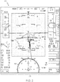
- FIG. 2 there is shown a screenshot of an exemplary CVPFD 40 generated on cockpit display device 18 during operation of cockpit display system 10 ( FIG. 1 ), as illustrated in accordance with an exemplary and non-limiting embodiment of the present invention.
- CVPFD 40 may thus correspond with 3D cockpit display 24 shown in FIG. 1 , although different reference numerals are utilized to emphasize that the appearance of the CVPFD and the below-described EFVI graphic will vary amongst different embodiments.
- CVPFD 40 is generated in a 3D, perspective view format from the vantage point of the aircraft.
- CVPFD 40 can be generated from other vantage points, such as that of a chase plane following the ownship A/C.
- EFVS image 42 and an SVS image 44 are integrated or combined to produce CVPFD 40.
- EFVS image 42 may be a smaller, centralized image that is inserted into (e.g., scaled, aligned, and blended with) with the larger SVS image 44.
- EFVS image 42 is generated utilizing real time data received from EFVS sensor 34 ( FIG. 1 ) to provide a pilot with visual information more closely resembling the actual flight environment of the ownship A/C.
- the larger SVS image 44 is generated utilizing information contained within one or more databases, such as navigational database 26 and/or terrain database 28 ( FIG. 1 ), and provides a broader context in which the focused EFVS image 42 can be better understood.
- CVPFD 40 includes various graphic elements and symbology that visually convey the current flight parameters of the ownship A/C. Many of the graphic elements of CVPFD 40 are well-known within the avionics industry and will not be described in detail herein. However, for completeness, it is briefly noted that the illustrated CVPFD 40 contains the following graphic elements: (i) a compass 46 centered about an A/C icon 48 (located in the bottom center of CVPFD 40 ); (ii) an airspeed indicator or "airspeed tape” 50, which features a precision readout window 52 (located in the upper left corner of CVPFD 40 ); (iii) an altitude indicator or "altitude tape” 54, which features a precision readout window 56 (located in the upper right corner of CVPFD 40 ) and a ground filled region 58; (iv) a barometric pressure setting readout 60 (located beneath altitude tape 54 ); (v) a flight path vector icon or flight path marker 62, which moves across CVPFD 40 to reflect changes
- CVPFD 40 is produced to include a runway graphic 66 representative of the runway approached by the ownship A/C.
- the runway represented by graphic 66 may or may not be detected by EFVS sensor 32.
- runway graphic 66 may thus be generated based upon database information stored within memory 22 ( FIG. 1 ), as may certain other elements appearing in EFVS image 42, which is combined or "blended" with the larger SVS image 44.
- the appearance of runway reference features apart from runway graphic 66, such as approach light graphics indicates that such features are detected by EFVS sensor 32.
- approach light graphics 68 within EFVS image 42 indicates that runway approach lights corresponding with graphics 68 are currently detected by EFVS sensor 32.
- approach light graphics 68 visually depict all of the runway approach lights thereby indicating that the runway approach lights are all currently detected by EFVS sensor 32.
- controller 12 further generates CVPFD 40 to include an EFVI graphic 70.
- EFVI graphic 70 can be generated as an enhanced flight visibility marker, which visually identifies a ground location beyond which the appearance of a graphic representative of a runway reference feature satisfies the flight visibility requirement. For this reason, EFVI graphic 70 will be referred to as "flight visibility marker 70" hereafter. This notwithstanding, it is emphasize that the EFVI graphic can assume any form that, when produced on CVPFD 40 or another 3D cockpit display, graphically conveys an enhanced flight visibility requirement for an approached runway. Additionally, the appearance of flight visibility marker 70 will vary amongst different embodiments of cockpit display system 10 and CVPFD 40. In the example of FIG.
- flight visibility marker 70 is generated as one or more forward portions 72 of a larger range ring, which is centered on the current A/C position and which is otherwise not displayed. Accordingly, flight visibility marker 70 may appear as two gently curved lines or arced segments 72(a)-(b), which are laterally separated by a central window 74.
- the provision of central window 74 minimizes the degree to which flight visibility marker 70 obscures runway graphic 66, approach light graphics 68, and other graphic elements of CVPFD 40.
- Approach light graphics 68 may successively pass through window 74 when the ownship A/C lands by head-on approach; that is, when the A/C remains substantially aligned with the centerline of the runway represented by graphic 66 through the approach.
- controller 12 determines the proper positioning of flight visibility marker 70 within the virtual, 3D environment of EFVS image 42.
- controller 12 may perform two general steps or processes to determine the proper positioning of flight visibility marker 70 within EFVS image 42 of CVPDF 40.
- controller 12 may establish the enhanced flight visibility requirement associated with or assigned to a runway currently approached by the ownship A/C for landing purposes.
- controller 12 may calculate or otherwise determine a ground location corresponding to the established flight visibility requirement.
- controller 12 may then generate CVPFD 40 to include flight visibility marker 70, as properly positioned in accordance with the determined ground location. Controller 12 may repeatedly perform these steps and update CVPFD 40 at a relatively rapid refresh rate to ensure that CVPFD 40 accurately reflects the real time or near real time flight environment of the ownship A/C.
- Controller 12 can establish the enhanced flight visibility requirement assigned to the approached runway in a number of different manners.
- controller 12 can recall the flight visibility requirement from a database stored in memory 22.
- a database stored in memory 22.
- navigation database 26 or terrain database 28 may contain approach charts corresponding to various different runways within range of the ownship A/C. The charts may set-out Runway Visual Range (RVR) value or a status miles value for each runway, which may then be extracted by controller 12 and utilized as the required flight visibility value.
- RVR Runway Visual Range
- memory 22 may contain a multi-dimensional look-up table or other tool for recalling enhanced flight visibility requirements corresponding to different runways.
- Controller 12 can also establish the enhanced flight visibility requirement from pilot input data received via pilot interface 16, such as an alphanumeric keypad included on a Multi-Purpose Control Display Unit (MCDU).
- controller can establish the flight visibility requirement from data received wirelessly via datalink 14 and provided by Air Traffic Control (ATC) or another recognized command authority.
- ATC Air Traffic Control
- controller 12 may recall a default value for the enhanced flight visibility requirement for the approached runway from memory 22, while permitting the default value to be overridden by information received via pilot interface 16 or via datalink 14.
- controller 12 can also be configured to adjust a baseline flight visibility requirement value in relation to changes in weather conditions, in relation to runway conditions affecting braking action, and the like.
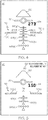
- FIG. 3 is a schematic diagram illustrating different manners in which the ground location of flight visibility marker 70 can be determined.
- the ground location can be determined by first establishing the current A/C height above the runway threshold.
- ground proximity sensor 30 FIG. 1
- controller 12 can adjust the current A/C height above ground level in accordance with such non-level ground topology.
- controller 12 can calculate the differential between these two values to arrive at the current A/C height above the runway threshold region.
- controller 12 can calculate the differential between these two values to arrive at the current A/C height above the runway threshold region.
- controller 12 can calculate the differential between these two values to arrive at the current A/C height above the runway threshold region.
- controller 12 can also be employed by controller 12 to determine the current A/C height above the runway threshold in further embodiments.
- controller 12 determines the ground location as a function of the current A/C height above the runway threshold and the value of the established flight visibility requirement. This can be accomplished by solving for the adjacent side of a right triangle including a (i) hypotenuse formed by a horizontal line extending toward the ownship A/C from the runway threshold region and (ii) an opposite side formed by vertical line extending downward from the ownship A/C to meet to the hypotenuse; as appearing herein, the term "vertical” defined as an axis parallel to the gravity vector, while the term “horizontal” is defined as an axis perpendicular to a vertical axis. Two examples are shown in FIG. 3 .
- the first example is represented by a triangle 80 having three sides: (i) a hypotenuse "H 1 ,” (ii) an adjacent side "A 1 ,” and (iii) an opposite side "O.”
- the length of the hypotenuse "Hi” is equal to the flight visibility requirement, which is established (e.g., extracted from an approach chart stored in memory 22 ) as an RVR value of 2400 feet in this example.
- the length of the opposite side “O” is the current A/C height above the runway threshold, which has been determined to be 200 feet.
- controller 12 need only solve for the length of an adjacent side "A 1 " to determine the ground location at which flight visibility marker 70 should be placed.
- controller 12 determines that the length of adjacent side "A" to be 2392 feet, as indicated in FIG. 3 by arrow 82. Controller 12 then generates flight visibility marker 70 to be positioned in accordance with this value, as considered in the virtual 3D context of CVPFD 40 ( FIG. 2 ). In the illustrated example wherein flight visibility marker 70 is generated as two forward portions 72(a)-(b) of a range ring centered on the current A/C position, the adjacent side "A 1 " of triangle 80 serves as a radius of the range ring, as indicated in FIG. 3 by arrow 88.
- triangle 84 includes the following sides: (i) a hypotenuse "H 2 ,” (ii) an adjacent side "A 2 ,” and (iii) an opposite side "O.”
- the flight visibility requirement RVR value
- the hypotenuse "H 2 " of triangle 84 is 1400 feet in length
- the opposite side "O" of triangle 84 is 200 feet in length.
- Controller 12 may thus solve for the length of adjacent side "A 2 " utilizing standard geometric or mathematical techniques. As indicated in FIG. 3 by arrow 86, controller 12 determines the length of adjacent side "A 2 " of triangle 84 to be 1384 feet in this second example. In further embodiments of cockpit display system 10 ( FIG. 1 ), controller 12 can determine the ground position of flight visibility marker 70 utilizing a different approach or technique.
- approach light graphics 68 depict all the runway approach lights ahead of the runway approached by the ownship A/C. As noted above, this indicates that that the current range of EFVS sensor 34 exceeds the distance currently separating the ownship A/C and the threshold of the runway (or at least the final row of runway approach lights located closest to the runway). Thus, in the scenario illustrated in FIG. 2 , the range of EFVS sensor 34 is relatively far-reaching and is likely more than sufficient to satisfy any published enhanced visibility requirements. It will often be the case, however, that the range of EFVS sensor 34 is curtailed by IMC or other low visibility conditions. In such cases, light approach graphics 68 will depict fewer than all of the runway approach on EFVS image 42 of CVPFD 40, as described below in conjunction with FIGs. 4 and 5 .
- FIGs. 4 and 5 are simplified views of EFVS image 42 of CFPFD 40 under different scenarios in which enhanced flight visibility requirements are satisfied and are not satisfied, respectively, for a runway approached for landing under IMC.
- graphics representative of seven rows of approach lights are shown and labeled as 68(a)-(g) with approach light rows 68(a) and 68(g) located closest to and furthest from the ownship A/C, respectively.
- approach light rows e.g., rows 68(e)-(g)
- flight visibility marker 70 provides a convenient visual reference by which a pilot can quickly ascertain whether a particular flight visibility requirement has been met when flying an approach under IMC.
- controller 12 FIG. 1
- controller 12 can alter the appearance of flight visibility marker 70 to visually convey additional pertinent information to the pilot pertaining to the enhanced flight visibility requirement.
- controller 12 can establish a decision altitude (DA) for the approached runway by, for example, recalling the DA from memory 22 or by calculating the DA based upon current flight parameters. Controller 12 can then alter the appearance of the EFVI graphic based, at least in part, on the current altitude of the ownship A/C relative to the established DA.
- DA decision altitude
- controller 12 can analyze EFVS image 42 to determine whether any approach light graphics 68 appear ahead of flight visibility marker 70, as considered from the vantage point of the ownship A/C. If determining that approach light graphics 68 do not appear ahead of flight visibility marker 70 as the ownship A/C descends below or is within a threshold distance of the DA, controller 12 may generate a visual caution alert or warning on CVPFD 40. For example, controller 12 may generate flight visibility marker 70 to have a pronounced appearance (e.g., increased dimensions) or otherwise draw the pilot's attention thereto; e.g., by applying a flashing effect or other animation effect to marker 70.
- the caution alert is generated by altering the appearing of flight visibility marker 70 from a default format wherein marker 70 is color coded in an information color (e.g., white or green; represented in FIG. 5 by a first cross-hatching pattern) to a caution format wherein marker 70 is color coded in a pre-established caution color (e.g., amber; represented by a second cross-hatching pattern).
- a textual message or annunciation 90 describing the caution alert may be generated on CVPFD 40, as indicated in upper right corner of FIG. 5 .
- cockpit display system 10 can generate other graphics or visual elements on EFVS image 42 or, more generally, CVPFD 40 indicating whether an enhanced flight visibility requirement for a runway approach by the ownship A/C is currently satisfied.
- controller 12 of cockpit display system 10 can process the data provided by EFVS sensor 32 ( FIG. 1 ) or analyze EFVS image 42 ( FIGs. 2 , 4, and 5 ) to establish the distance between a present position of the ownship A/C and the lighting signature located furthest from the present A/C position. This distance may then be compared with the enhanced visibility requirement for the approached runway to determine whether the enhanced visibility requirement is currently satisfied.
- controller 12 can then generate EFVS image 42 (or CVPFD 40) to include additional graphics or a text annunciation indicating whether the enhanced visibility requirement is satisfied for the approached runway. For example, if determining that an enhanced flight visibility requirement is not currently satisfied for an approached runway approach, controller 12 can generate EFVS image 42 to include a text annunciation similar or identical to annunciation 90 shown in FIG. 5 . Conversely, if determining that an enhanced flight visibility requirement is currently satisfied, controller 12 can generate EFVS image 42 to include a corresponding text annunciation. In such embodiments, controller 12 of cockpit display system 10 may or may not generate EFVS image 42 to further include flight visibility marker 70.
- Embodiments of the above-described cockpit display system supplement an EFVS image with additional visual information indicating whether enhanced flight visibility requirements are satisfied during approach and landing, especially when conducted under IMC.
- an EFVI graphic may be generated on the EFVS image.
- the EFVI graphic can be a flight visibility marker, which identifies a ground location beyond which the appearance of a runway reference feature (e.g., a graphic symbolizing or depicting one or more runway approach lights) satisfies the flight visibility requirement.
- the EFVS image can be generated as standalone image or included in a CVS display, such as a CVPFD, which is produced various different types of display device devices (e.g., a HDD or HUD display device) when located within the cockpit of an A/C.
- a CVS display such as a CVPFD
- various different types of display device devices e.g., a HDD or HUD display device
- the EFVI graphic provides a definitive reference to determine the enhanced flight visibility thereby easing the mental burden on the pilot in a high workload environment.
- the EFVI graphic may help simplify the pilot's task of locating required visual references when conducting an EFVS approach under IMC or other low visibility conditions.
- the cockpit display system may comprise graphical user interface (e.g., ARINC 661) components, which may include a user application definition file ("UADF").
- UADF user application definition file
Landscapes
- Engineering & Computer Science (AREA)
- Aviation & Aerospace Engineering (AREA)
- Physics & Mathematics (AREA)
- General Physics & Mathematics (AREA)
- Radar, Positioning & Navigation (AREA)
- Remote Sensing (AREA)
- Multimedia (AREA)
- Signal Processing (AREA)
- Traffic Control Systems (AREA)
Applications Claiming Priority (1)
| Application Number | Priority Date | Filing Date | Title |
|---|---|---|---|
| US15/007,673 US9936191B2 (en) | 2016-01-27 | 2016-01-27 | Cockpit display systems and methods for generating cockpit displays including enhanced flight visibility indicators |
Publications (2)
| Publication Number | Publication Date |
|---|---|
| EP3199918A1 true EP3199918A1 (de) | 2017-08-02 |
| EP3199918B1 EP3199918B1 (de) | 2020-03-11 |
Family
ID=57796221
Family Applications (1)
| Application Number | Title | Priority Date | Filing Date |
|---|---|---|---|
| EP17151291.6A Active EP3199918B1 (de) | 2016-01-27 | 2017-01-12 | Cockpitanzeigesysteme und verfahren zur erzeugung von cockpitanzeigen mit indikatoren für verbesserte flugsicht |
Country Status (3)
| Country | Link |
|---|---|
| US (1) | US9936191B2 (de) |
| EP (1) | EP3199918B1 (de) |
| CN (1) | CN107010239B (de) |
Cited By (1)
| Publication number | Priority date | Publication date | Assignee | Title |
|---|---|---|---|---|
| US10672282B2 (en) | 2018-08-24 | 2020-06-02 | Honeywell International Inc. | Particle sensor system and method to determine visibility for a vehicle |
Families Citing this family (16)
| Publication number | Priority date | Publication date | Assignee | Title |
|---|---|---|---|---|
| FR3049744B1 (fr) * | 2016-04-01 | 2018-03-30 | Thales | Procede de representation synthetique d'elements d'interet dans un systeme de visualisation pour aeronef |
| FR3068481B1 (fr) * | 2017-06-29 | 2019-07-26 | Airbus Operations (S.A.S.) | Systeme et procede d'affichage pour un aeronef |
| US10399698B2 (en) * | 2017-09-16 | 2019-09-03 | Rockwell Collins, Inc. | Systems and methods for smart vision runway landing display |
| US10607494B2 (en) * | 2017-10-05 | 2020-03-31 | 3764729 Canada Inc. | Aircraft approach chart |
| GB2570497B (en) | 2018-01-29 | 2020-07-29 | Ge Aviat Systems Ltd | Aerial vehicles with machine vision |
| CN108974374B (zh) * | 2018-08-08 | 2021-11-19 | 缪纪生 | 全天候视景引导着陆系统 |
| US11359931B2 (en) * | 2018-10-11 | 2022-06-14 | Bombardier Inc. | Vision guidance systems and methods for aircraft |
| CN109613929B (zh) * | 2018-12-12 | 2022-11-25 | 北京卫星信息工程研究所 | 一种航班精密进近与着陆方法及系统 |
| US11592315B1 (en) * | 2019-03-08 | 2023-02-28 | John M. Wilson | Aircraft flare-assist landing system |
| EP3730901A3 (de) | 2019-04-01 | 2020-12-30 | Bombardier Inc. | Flugzeugsystem und verfahren zur unterstützung eines piloten während des fluges |
| US20210004749A1 (en) * | 2019-07-02 | 2021-01-07 | The Boeing Company | Systems and methods for remotely monitoring an aircraft |
| EP3816585A1 (de) * | 2019-10-28 | 2021-05-05 | Bombardier Inc. | Anzeigesysteme und verfahren für ein flugzeug |
| CN114084357B (zh) * | 2021-12-10 | 2023-12-29 | 安胜(天津)飞行模拟系统有限公司 | 一种基于eVTOL飞机的驾驶舱显示系统 |
| US20230391472A1 (en) * | 2022-06-06 | 2023-12-07 | Honeywell International Inc. | System and method for assisting a non-pilot in taking corrective action |
| US20240101273A1 (en) * | 2022-09-26 | 2024-03-28 | Rockwell Collins, Inc. | Pilot alerting of detected runway environment |
| US20250006065A1 (en) * | 2023-06-30 | 2025-01-02 | Mark Krietzman | Real time alert for landing airplanes |
Citations (1)
| Publication number | Priority date | Publication date | Assignee | Title |
|---|---|---|---|---|
| EP2416124A2 (de) * | 2010-08-03 | 2012-02-08 | Honeywell International, Inc. | Verbessertes Flugsichtsystem zur Verbesserung von Anflugpistensignaturen |
Family Cites Families (26)
| Publication number | Priority date | Publication date | Assignee | Title |
|---|---|---|---|---|
| US5593114A (en) * | 1994-04-19 | 1997-01-14 | Mcdonnell Douglas Corporation | Synthetic vision automatic landing system |
| US6693559B1 (en) * | 2000-09-19 | 2004-02-17 | Honeywell International Inc. | System and method for flight mode annunciators |
| WO2006049643A2 (en) | 2004-04-05 | 2006-05-11 | U.S. Government As Represented By The Secretary Of Army | Airborne visibility indicator system and method |
| US7693621B1 (en) | 2006-06-27 | 2010-04-06 | Toyota Motor Sales, U.S.A., Inc. | Apparatus and methods for displaying arrival, approach, and departure information on a display device in an aircraft |
| US7605719B1 (en) * | 2007-07-25 | 2009-10-20 | Rockwell Collins, Inc. | System and methods for displaying a partial images and non-overlapping, shared-screen partial images acquired from vision systems |
| US7965223B1 (en) * | 2009-02-03 | 2011-06-21 | Rockwell Collins, Inc. | Forward-looking radar system, module, and method for generating and/or presenting airport surface traffic information |
| US8175761B2 (en) * | 2009-02-17 | 2012-05-08 | Honeywell International Inc. | System and method for rendering a synthetic perspective display of a designated object or location |
| US8195347B2 (en) | 2009-05-28 | 2012-06-05 | The Boeing Company | Method and system for approach decision display |
| US20110196598A1 (en) * | 2010-02-09 | 2011-08-11 | Honeywell International Inc. | System and methods for rendering taxiway and runway signage in a synthetic display of an airport field |
| US20110282580A1 (en) * | 2010-05-11 | 2011-11-17 | Honeywell International Inc. | Method of image based navigation for precision guidance and landing |
| US9494447B2 (en) * | 2010-07-28 | 2016-11-15 | Honeywell International Inc. | Methods and systems for attitude differentiation in enhanced vision images |
| US8487787B2 (en) * | 2010-09-30 | 2013-07-16 | Honeywell International Inc. | Near-to-eye head tracking ground obstruction system and method |
| US20120140125A1 (en) * | 2010-12-03 | 2012-06-07 | Honeywell International Inc. | Aircraft cockpit visor display |
| US9092975B2 (en) | 2011-02-23 | 2015-07-28 | Honeywell International Inc. | Aircraft systems and methods for displaying visual segment information |
| US9404767B2 (en) * | 2011-06-10 | 2016-08-02 | The Boeing Company | Methods and systems for performing charting tasks |
| US9013330B2 (en) * | 2011-09-01 | 2015-04-21 | Honeywell International Inc. | Electric taxi system guidance |
| US8676399B2 (en) * | 2011-11-21 | 2014-03-18 | Honeywell International Inc. | System and method for generating and displaying an electric taxi index |
| US9390559B2 (en) * | 2013-03-12 | 2016-07-12 | Honeywell International Inc. | Aircraft flight deck displays and systems and methods for enhanced display of obstacles in a combined vision display |
| US9517844B2 (en) * | 2013-09-25 | 2016-12-13 | Honeywell International Inc. | System and method for displaying airport features on a dynamic airport moving map display |
| US9142133B2 (en) * | 2013-10-29 | 2015-09-22 | Honeywell International Inc. | System and method for maintaining aircraft separation based on distance or time |
| US9428056B2 (en) * | 2014-03-11 | 2016-08-30 | Textron Innovations, Inc. | Adjustable synthetic vision |
| US9532013B1 (en) * | 2014-06-03 | 2016-12-27 | Rockwell Collins, Inc. | Sensor-based image(s) integrity determination system, device, and method |
| US9174746B1 (en) * | 2014-06-26 | 2015-11-03 | Rockwell Collins, Inc. | Visual aid generating system, device, and method |
| US9746343B1 (en) * | 2014-07-31 | 2017-08-29 | Rockwell Collins, Inc. | Steering command generating system, device, and method for a forward-looking image capture device |
| CN104766337B (zh) * | 2015-04-27 | 2017-10-20 | 西北工业大学 | 一种基于跑道边界增强的飞机着陆视觉增强方法 |
| US9418408B1 (en) * | 2015-07-22 | 2016-08-16 | Rockwell Collins, Inc. | Dynamic range optimization |
-
2016
- 2016-01-27 US US15/007,673 patent/US9936191B2/en active Active
-
2017
- 2017-01-12 EP EP17151291.6A patent/EP3199918B1/de active Active
- 2017-01-26 CN CN201710057084.6A patent/CN107010239B/zh active Active
Patent Citations (1)
| Publication number | Priority date | Publication date | Assignee | Title |
|---|---|---|---|---|
| EP2416124A2 (de) * | 2010-08-03 | 2012-02-08 | Honeywell International, Inc. | Verbessertes Flugsichtsystem zur Verbesserung von Anflugpistensignaturen |
Cited By (1)
| Publication number | Priority date | Publication date | Assignee | Title |
|---|---|---|---|---|
| US10672282B2 (en) | 2018-08-24 | 2020-06-02 | Honeywell International Inc. | Particle sensor system and method to determine visibility for a vehicle |
Also Published As
| Publication number | Publication date |
|---|---|
| EP3199918B1 (de) | 2020-03-11 |
| US9936191B2 (en) | 2018-04-03 |
| CN107010239A (zh) | 2017-08-04 |
| CN107010239B (zh) | 2022-07-12 |
| US20170214904A1 (en) | 2017-07-27 |
Similar Documents
| Publication | Publication Date | Title |
|---|---|---|
| EP3199918B1 (de) | Cockpitanzeigesysteme und verfahren zur erzeugung von cockpitanzeigen mit indikatoren für verbesserte flugsicht | |
| US7908078B2 (en) | Perspective-view visual runway awareness and advisory display | |
| US11941995B2 (en) | Runway awareness and alerting systems and methods | |
| EP3321634B1 (de) | System und verfahren zur anzeige von landebahnüberschreitungsinformationen | |
| EP2224216B1 (de) | System und Verfahren zur Erzeugung einer primären Fluganzeige mit einem konformen Bodenvermeidungsführungselement | |
| US9139307B2 (en) | Aircraft systems and methods for displaying runway lighting information | |
| EP3125213B1 (de) | Flugzeugbordsysteme und verfahren zur identifizierung von beweglichen landeplattformen | |
| EP2650858A2 (de) | Systeme und Verfahren zur Verbesserung der Landebahnerkennung mit Start- und Landeleistungsdaten | |
| EP2154665A2 (de) | Automatische Landebereichserkennung für ein Flugzeug | |
| EP2194361B1 (de) | System zur Verbesserung des Hindernis- und Geländeprofilbewusstseins | |
| EP2413101A1 (de) | Verfahren und System zur Lagedifferenzierung in erweiterten Sichtbildern einer Cockpitanzeige eines Luffahrzeuges | |
| EP2919219B1 (de) | System und Verfahren zur Identifizierung der Rollbahnposition während des Abflugs auf einer Rollbahneinmündung | |
| EP2196774A2 (de) | System und Verfahren zur Bildberechnung einer primären Fluganzeige mit einem Fluglagenrahmenelement | |
| US20100321488A1 (en) | Landing aid device and method | |
| EP3309519B1 (de) | Flugzeugsystem und entsprechendes verfahren zur anzeige von windscherung | |
| EP2204639A1 (de) | Systeme und Verfahren zur Verbesserung des Geländeanhebungsbewusstseins | |
| US10854091B2 (en) | Energy management visualization methods and systems | |
| EP3079138A2 (de) | Flugzeugsysteme und verfahren zum anzeigen einer verbesserten landebahnbeleuchtung | |
| US20130300587A1 (en) | System and method for displaying runway approach texture objects | |
| US20140207315A1 (en) | Apparatus and method for displaying a helicopter terrain intercept point during landing | |
| US11345484B2 (en) | Display system of an aircraft, able to display a localization marking of a zone of location of an approach light ramp and related method | |
| US12165525B2 (en) | Comparative vertical profile displays | |
| EP4209756A1 (de) | Vergleichende vertikalprofilanzeigen |
Legal Events
| Date | Code | Title | Description |
|---|---|---|---|
| PUAI | Public reference made under article 153(3) epc to a published international application that has entered the european phase |
Free format text: ORIGINAL CODE: 0009012 |
|
| STAA | Information on the status of an ep patent application or granted ep patent |
Free format text: STATUS: REQUEST FOR EXAMINATION WAS MADE |
|
| 17P | Request for examination filed |
Effective date: 20170112 |
|
| AK | Designated contracting states |
Kind code of ref document: A1 Designated state(s): AL AT BE BG CH CY CZ DE DK EE ES FI FR GB GR HR HU IE IS IT LI LT LU LV MC MK MT NL NO PL PT RO RS SE SI SK SM TR |
|
| AX | Request for extension of the european patent |
Extension state: BA ME |
|
| GRAP | Despatch of communication of intention to grant a patent |
Free format text: ORIGINAL CODE: EPIDOSNIGR1 |
|
| STAA | Information on the status of an ep patent application or granted ep patent |
Free format text: STATUS: GRANT OF PATENT IS INTENDED |
|
| INTG | Intention to grant announced |
Effective date: 20191011 |
|
| RIN1 | Information on inventor provided before grant (corrected) |
Inventor name: TUNHEIM, DAVID ALLEN Inventor name: HE, GANG Inventor name: WYATT, IVAN SANDY |
|
| GRAS | Grant fee paid |
Free format text: ORIGINAL CODE: EPIDOSNIGR3 |
|
| GRAA | (expected) grant |
Free format text: ORIGINAL CODE: 0009210 |
|
| STAA | Information on the status of an ep patent application or granted ep patent |
Free format text: STATUS: THE PATENT HAS BEEN GRANTED |
|
| AK | Designated contracting states |
Kind code of ref document: B1 Designated state(s): AL AT BE BG CH CY CZ DE DK EE ES FI FR GB GR HR HU IE IS IT LI LT LU LV MC MK MT NL NO PL PT RO RS SE SI SK SM TR |
|
| REG | Reference to a national code |
Ref country code: GB Ref legal event code: FG4D |
|
| REG | Reference to a national code |
Ref country code: CH Ref legal event code: EP |
|
| REG | Reference to a national code |
Ref country code: AT Ref legal event code: REF Ref document number: 1243694 Country of ref document: AT Kind code of ref document: T Effective date: 20200315 |
|
| REG | Reference to a national code |
Ref country code: IE Ref legal event code: FG4D |
|
| REG | Reference to a national code |
Ref country code: DE Ref legal event code: R096 Ref document number: 602017012752 Country of ref document: DE |
|
| PG25 | Lapsed in a contracting state [announced via postgrant information from national office to epo] |
Ref country code: RS Free format text: LAPSE BECAUSE OF FAILURE TO SUBMIT A TRANSLATION OF THE DESCRIPTION OR TO PAY THE FEE WITHIN THE PRESCRIBED TIME-LIMIT Effective date: 20200311 Ref country code: FI Free format text: LAPSE BECAUSE OF FAILURE TO SUBMIT A TRANSLATION OF THE DESCRIPTION OR TO PAY THE FEE WITHIN THE PRESCRIBED TIME-LIMIT Effective date: 20200311 Ref country code: NO Free format text: LAPSE BECAUSE OF FAILURE TO SUBMIT A TRANSLATION OF THE DESCRIPTION OR TO PAY THE FEE WITHIN THE PRESCRIBED TIME-LIMIT Effective date: 20200611 |
|
| REG | Reference to a national code |
Ref country code: NL Ref legal event code: MP Effective date: 20200311 |
|
| PG25 | Lapsed in a contracting state [announced via postgrant information from national office to epo] |
Ref country code: HR Free format text: LAPSE BECAUSE OF FAILURE TO SUBMIT A TRANSLATION OF THE DESCRIPTION OR TO PAY THE FEE WITHIN THE PRESCRIBED TIME-LIMIT Effective date: 20200311 Ref country code: LV Free format text: LAPSE BECAUSE OF FAILURE TO SUBMIT A TRANSLATION OF THE DESCRIPTION OR TO PAY THE FEE WITHIN THE PRESCRIBED TIME-LIMIT Effective date: 20200311 Ref country code: SE Free format text: LAPSE BECAUSE OF FAILURE TO SUBMIT A TRANSLATION OF THE DESCRIPTION OR TO PAY THE FEE WITHIN THE PRESCRIBED TIME-LIMIT Effective date: 20200311 Ref country code: BG Free format text: LAPSE BECAUSE OF FAILURE TO SUBMIT A TRANSLATION OF THE DESCRIPTION OR TO PAY THE FEE WITHIN THE PRESCRIBED TIME-LIMIT Effective date: 20200611 Ref country code: GR Free format text: LAPSE BECAUSE OF FAILURE TO SUBMIT A TRANSLATION OF THE DESCRIPTION OR TO PAY THE FEE WITHIN THE PRESCRIBED TIME-LIMIT Effective date: 20200612 |
|
| REG | Reference to a national code |
Ref country code: LT Ref legal event code: MG4D |
|
| PG25 | Lapsed in a contracting state [announced via postgrant information from national office to epo] |
Ref country code: NL Free format text: LAPSE BECAUSE OF FAILURE TO SUBMIT A TRANSLATION OF THE DESCRIPTION OR TO PAY THE FEE WITHIN THE PRESCRIBED TIME-LIMIT Effective date: 20200311 |
|
| PG25 | Lapsed in a contracting state [announced via postgrant information from national office to epo] |
Ref country code: LT Free format text: LAPSE BECAUSE OF FAILURE TO SUBMIT A TRANSLATION OF THE DESCRIPTION OR TO PAY THE FEE WITHIN THE PRESCRIBED TIME-LIMIT Effective date: 20200311 Ref country code: RO Free format text: LAPSE BECAUSE OF FAILURE TO SUBMIT A TRANSLATION OF THE DESCRIPTION OR TO PAY THE FEE WITHIN THE PRESCRIBED TIME-LIMIT Effective date: 20200311 Ref country code: CZ Free format text: LAPSE BECAUSE OF FAILURE TO SUBMIT A TRANSLATION OF THE DESCRIPTION OR TO PAY THE FEE WITHIN THE PRESCRIBED TIME-LIMIT Effective date: 20200311 Ref country code: EE Free format text: LAPSE BECAUSE OF FAILURE TO SUBMIT A TRANSLATION OF THE DESCRIPTION OR TO PAY THE FEE WITHIN THE PRESCRIBED TIME-LIMIT Effective date: 20200311 Ref country code: SM Free format text: LAPSE BECAUSE OF FAILURE TO SUBMIT A TRANSLATION OF THE DESCRIPTION OR TO PAY THE FEE WITHIN THE PRESCRIBED TIME-LIMIT Effective date: 20200311 Ref country code: SK Free format text: LAPSE BECAUSE OF FAILURE TO SUBMIT A TRANSLATION OF THE DESCRIPTION OR TO PAY THE FEE WITHIN THE PRESCRIBED TIME-LIMIT Effective date: 20200311 Ref country code: IS Free format text: LAPSE BECAUSE OF FAILURE TO SUBMIT A TRANSLATION OF THE DESCRIPTION OR TO PAY THE FEE WITHIN THE PRESCRIBED TIME-LIMIT Effective date: 20200711 Ref country code: PT Free format text: LAPSE BECAUSE OF FAILURE TO SUBMIT A TRANSLATION OF THE DESCRIPTION OR TO PAY THE FEE WITHIN THE PRESCRIBED TIME-LIMIT Effective date: 20200805 |
|
| REG | Reference to a national code |
Ref country code: AT Ref legal event code: MK05 Ref document number: 1243694 Country of ref document: AT Kind code of ref document: T Effective date: 20200311 |
|
| REG | Reference to a national code |
Ref country code: DE Ref legal event code: R097 Ref document number: 602017012752 Country of ref document: DE |
|
| PLBE | No opposition filed within time limit |
Free format text: ORIGINAL CODE: 0009261 |
|
| STAA | Information on the status of an ep patent application or granted ep patent |
Free format text: STATUS: NO OPPOSITION FILED WITHIN TIME LIMIT |
|
| PG25 | Lapsed in a contracting state [announced via postgrant information from national office to epo] |
Ref country code: ES Free format text: LAPSE BECAUSE OF FAILURE TO SUBMIT A TRANSLATION OF THE DESCRIPTION OR TO PAY THE FEE WITHIN THE PRESCRIBED TIME-LIMIT Effective date: 20200311 Ref country code: DK Free format text: LAPSE BECAUSE OF FAILURE TO SUBMIT A TRANSLATION OF THE DESCRIPTION OR TO PAY THE FEE WITHIN THE PRESCRIBED TIME-LIMIT Effective date: 20200311 Ref country code: IT Free format text: LAPSE BECAUSE OF FAILURE TO SUBMIT A TRANSLATION OF THE DESCRIPTION OR TO PAY THE FEE WITHIN THE PRESCRIBED TIME-LIMIT Effective date: 20200311 Ref country code: AT Free format text: LAPSE BECAUSE OF FAILURE TO SUBMIT A TRANSLATION OF THE DESCRIPTION OR TO PAY THE FEE WITHIN THE PRESCRIBED TIME-LIMIT Effective date: 20200311 |
|
| 26N | No opposition filed |
Effective date: 20201214 |
|
| PG25 | Lapsed in a contracting state [announced via postgrant information from national office to epo] |
Ref country code: SI Free format text: LAPSE BECAUSE OF FAILURE TO SUBMIT A TRANSLATION OF THE DESCRIPTION OR TO PAY THE FEE WITHIN THE PRESCRIBED TIME-LIMIT Effective date: 20200311 Ref country code: PL Free format text: LAPSE BECAUSE OF FAILURE TO SUBMIT A TRANSLATION OF THE DESCRIPTION OR TO PAY THE FEE WITHIN THE PRESCRIBED TIME-LIMIT Effective date: 20200311 |
|
| PG25 | Lapsed in a contracting state [announced via postgrant information from national office to epo] |
Ref country code: MC Free format text: LAPSE BECAUSE OF FAILURE TO SUBMIT A TRANSLATION OF THE DESCRIPTION OR TO PAY THE FEE WITHIN THE PRESCRIBED TIME-LIMIT Effective date: 20200311 |
|
| REG | Reference to a national code |
Ref country code: CH Ref legal event code: PL |
|
| PG25 | Lapsed in a contracting state [announced via postgrant information from national office to epo] |
Ref country code: LU Free format text: LAPSE BECAUSE OF NON-PAYMENT OF DUE FEES Effective date: 20210112 |
|
| REG | Reference to a national code |
Ref country code: BE Ref legal event code: MM Effective date: 20210131 |
|
| PG25 | Lapsed in a contracting state [announced via postgrant information from national office to epo] |
Ref country code: LI Free format text: LAPSE BECAUSE OF NON-PAYMENT OF DUE FEES Effective date: 20210131 Ref country code: CH Free format text: LAPSE BECAUSE OF NON-PAYMENT OF DUE FEES Effective date: 20210131 |
|
| PG25 | Lapsed in a contracting state [announced via postgrant information from national office to epo] |
Ref country code: IE Free format text: LAPSE BECAUSE OF NON-PAYMENT OF DUE FEES Effective date: 20210112 |
|
| PG25 | Lapsed in a contracting state [announced via postgrant information from national office to epo] |
Ref country code: BE Free format text: LAPSE BECAUSE OF NON-PAYMENT OF DUE FEES Effective date: 20210131 |
|
| PG25 | Lapsed in a contracting state [announced via postgrant information from national office to epo] |
Ref country code: HU Free format text: LAPSE BECAUSE OF FAILURE TO SUBMIT A TRANSLATION OF THE DESCRIPTION OR TO PAY THE FEE WITHIN THE PRESCRIBED TIME-LIMIT; INVALID AB INITIO Effective date: 20170112 |
|
| PG25 | Lapsed in a contracting state [announced via postgrant information from national office to epo] |
Ref country code: CY Free format text: LAPSE BECAUSE OF FAILURE TO SUBMIT A TRANSLATION OF THE DESCRIPTION OR TO PAY THE FEE WITHIN THE PRESCRIBED TIME-LIMIT Effective date: 20200311 |
|
| P01 | Opt-out of the competence of the unified patent court (upc) registered |
Effective date: 20230525 |
|
| PG25 | Lapsed in a contracting state [announced via postgrant information from national office to epo] |
Ref country code: MK Free format text: LAPSE BECAUSE OF FAILURE TO SUBMIT A TRANSLATION OF THE DESCRIPTION OR TO PAY THE FEE WITHIN THE PRESCRIBED TIME-LIMIT Effective date: 20200311 |
|
| PG25 | Lapsed in a contracting state [announced via postgrant information from national office to epo] |
Ref country code: MT Free format text: LAPSE BECAUSE OF FAILURE TO SUBMIT A TRANSLATION OF THE DESCRIPTION OR TO PAY THE FEE WITHIN THE PRESCRIBED TIME-LIMIT Effective date: 20200311 |
|
| PG25 | Lapsed in a contracting state [announced via postgrant information from national office to epo] |
Ref country code: TR Free format text: LAPSE BECAUSE OF FAILURE TO SUBMIT A TRANSLATION OF THE DESCRIPTION OR TO PAY THE FEE WITHIN THE PRESCRIBED TIME-LIMIT Effective date: 20200311 |
|
| PGFP | Annual fee paid to national office [announced via postgrant information from national office to epo] |
Ref country code: GB Payment date: 20260126 Year of fee payment: 10 |
|
| PGFP | Annual fee paid to national office [announced via postgrant information from national office to epo] |
Ref country code: DE Payment date: 20260127 Year of fee payment: 10 |
|
| PGFP | Annual fee paid to national office [announced via postgrant information from national office to epo] |
Ref country code: FR Payment date: 20260127 Year of fee payment: 10 |