EP3199963B1 - Magnetfeldsensor mit mehreren messschichtmagnetisierungsausrichtungen - Google Patents
Magnetfeldsensor mit mehreren messschichtmagnetisierungsausrichtungen Download PDFInfo
- Publication number
- EP3199963B1 EP3199963B1 EP17153302.9A EP17153302A EP3199963B1 EP 3199963 B1 EP3199963 B1 EP 3199963B1 EP 17153302 A EP17153302 A EP 17153302A EP 3199963 B1 EP3199963 B1 EP 3199963B1
- Authority
- EP
- European Patent Office
- Prior art keywords
- sense
- magnetic field
- plane
- layer
- magnetoresistive
- Prior art date
- Legal status (The legal status is an assumption and is not a legal conclusion. Google has not performed a legal analysis and makes no representation as to the accuracy of the status listed.)
- Active
Links
- 230000005291 magnetic effect Effects 0.000 title claims description 266
- 230000005415 magnetization Effects 0.000 title claims description 142
- 230000004044 response Effects 0.000 claims description 16
- 238000001514 detection method Methods 0.000 claims description 4
- 238000000034 method Methods 0.000 description 28
- 230000005294 ferromagnetic effect Effects 0.000 description 18
- 230000008569 process Effects 0.000 description 18
- 239000013598 vector Substances 0.000 description 18
- 230000004907 flux Effects 0.000 description 17
- 238000004519 manufacturing process Methods 0.000 description 16
- 238000010586 diagram Methods 0.000 description 8
- 239000000463 material Substances 0.000 description 7
- 230000008878 coupling Effects 0.000 description 6
- 238000010168 coupling process Methods 0.000 description 6
- 238000005859 coupling reaction Methods 0.000 description 6
- 239000003989 dielectric material Substances 0.000 description 6
- 238000013461 design Methods 0.000 description 5
- 230000000694 effects Effects 0.000 description 5
- 238000012360 testing method Methods 0.000 description 5
- 229910045601 alloy Inorganic materials 0.000 description 4
- 239000000956 alloy Substances 0.000 description 4
- 238000004891 communication Methods 0.000 description 4
- 238000010438 heat treatment Methods 0.000 description 4
- 230000035945 sensitivity Effects 0.000 description 4
- 239000012212 insulator Substances 0.000 description 3
- XEEYBQQBJWHFJM-UHFFFAOYSA-N iron Substances [Fe] XEEYBQQBJWHFJM-UHFFFAOYSA-N 0.000 description 3
- PXHVJJICTQNCMI-UHFFFAOYSA-N nickel Substances [Ni] PXHVJJICTQNCMI-UHFFFAOYSA-N 0.000 description 3
- 230000009471 action Effects 0.000 description 2
- 230000001808 coupling effect Effects 0.000 description 2
- 238000000151 deposition Methods 0.000 description 2
- 230000001627 detrimental effect Effects 0.000 description 2
- 238000005530 etching Methods 0.000 description 2
- 230000012447 hatching Effects 0.000 description 2
- 229910052742 iron Inorganic materials 0.000 description 2
- 229910052751 metal Inorganic materials 0.000 description 2
- 239000002184 metal Substances 0.000 description 2
- 229910052759 nickel Inorganic materials 0.000 description 2
- 238000009659 non-destructive testing Methods 0.000 description 2
- 230000003071 parasitic effect Effects 0.000 description 2
- 238000000059 patterning Methods 0.000 description 2
- 238000011160 research Methods 0.000 description 2
- 239000007787 solid Substances 0.000 description 2
- 230000003321 amplification Effects 0.000 description 1
- 230000005290 antiferromagnetic effect Effects 0.000 description 1
- 230000015572 biosynthetic process Effects 0.000 description 1
- 229910052804 chromium Inorganic materials 0.000 description 1
- 229910017052 cobalt Inorganic materials 0.000 description 1
- 239000010941 cobalt Substances 0.000 description 1
- GUTLYIVDDKVIGB-UHFFFAOYSA-N cobalt atom Chemical compound [Co] GUTLYIVDDKVIGB-UHFFFAOYSA-N 0.000 description 1
- 230000003750 conditioning effect Effects 0.000 description 1
- 229910052802 copper Inorganic materials 0.000 description 1
- 238000013523 data management Methods 0.000 description 1
- 230000008021 deposition Effects 0.000 description 1
- 230000009977 dual effect Effects 0.000 description 1
- 239000003302 ferromagnetic material Substances 0.000 description 1
- 229910052737 gold Inorganic materials 0.000 description 1
- 229910052735 hafnium Inorganic materials 0.000 description 1
- 239000000696 magnetic material Substances 0.000 description 1
- 238000012986 modification Methods 0.000 description 1
- 230000004048 modification Effects 0.000 description 1
- 229910052758 niobium Inorganic materials 0.000 description 1
- 238000003199 nucleic acid amplification method Methods 0.000 description 1
- 230000003287 optical effect Effects 0.000 description 1
- 238000004806 packaging method and process Methods 0.000 description 1
- 229910052763 palladium Inorganic materials 0.000 description 1
- 230000002085 persistent effect Effects 0.000 description 1
- 229910052697 platinum Inorganic materials 0.000 description 1
- 230000010287 polarization Effects 0.000 description 1
- 238000012545 processing Methods 0.000 description 1
- 229910052761 rare earth metal Inorganic materials 0.000 description 1
- 150000002910 rare earth metals Chemical class 0.000 description 1
- 239000004065 semiconductor Substances 0.000 description 1
- 229910052709 silver Inorganic materials 0.000 description 1
- 230000006641 stabilisation Effects 0.000 description 1
- 238000011105 stabilization Methods 0.000 description 1
- 229910052715 tantalum Inorganic materials 0.000 description 1
- 229910052719 titanium Inorganic materials 0.000 description 1
- 229910052720 vanadium Inorganic materials 0.000 description 1
Images


Classifications
-
- G—PHYSICS
- G01—MEASURING; TESTING
- G01R—MEASURING ELECTRIC VARIABLES; MEASURING MAGNETIC VARIABLES
- G01R33/00—Arrangements or instruments for measuring magnetic variables
- G01R33/0005—Geometrical arrangement of magnetic sensor elements; Apparatus combining different magnetic sensor types
-
- G—PHYSICS
- G01—MEASURING; TESTING
- G01R—MEASURING ELECTRIC VARIABLES; MEASURING MAGNETIC VARIABLES
- G01R17/00—Measuring arrangements involving comparison with a reference value, e.g. bridge
- G01R17/10—AC or DC measuring bridges
-
- G—PHYSICS
- G01—MEASURING; TESTING
- G01R—MEASURING ELECTRIC VARIABLES; MEASURING MAGNETIC VARIABLES
- G01R33/00—Arrangements or instruments for measuring magnetic variables
- G01R33/0011—Arrangements or instruments for measuring magnetic variables comprising means, e.g. flux concentrators, flux guides, for guiding or concentrating the magnetic flux, e.g. to the magnetic sensor
-
- G—PHYSICS
- G01—MEASURING; TESTING
- G01R—MEASURING ELECTRIC VARIABLES; MEASURING MAGNETIC VARIABLES
- G01R33/00—Arrangements or instruments for measuring magnetic variables
- G01R33/02—Measuring direction or magnitude of magnetic fields or magnetic flux
- G01R33/06—Measuring direction or magnitude of magnetic fields or magnetic flux using galvano-magnetic devices
- G01R33/09—Magnetoresistive devices
- G01R33/093—Magnetoresistive devices using multilayer structures, e.g. giant magnetoresistance sensors
-
- G—PHYSICS
- G01—MEASURING; TESTING
- G01R—MEASURING ELECTRIC VARIABLES; MEASURING MAGNETIC VARIABLES
- G01R33/00—Arrangements or instruments for measuring magnetic variables
- G01R33/02—Measuring direction or magnitude of magnetic fields or magnetic flux
- G01R33/06—Measuring direction or magnitude of magnetic fields or magnetic flux using galvano-magnetic devices
- G01R33/09—Magnetoresistive devices
- G01R33/098—Magnetoresistive devices comprising tunnel junctions, e.g. tunnel magnetoresistance sensors
Definitions
- the present invention relates generally to magnetoelectronic devices. More specifically, the present invention relates to a magnetic field sensor with multiple axis sensing and permanent magnet biasing.
- Magnetic field sensors also known as magnetometers, are widely used in a number of applications including in, for example, compass, security, and military applications, geophysics and space research, biomagnetism and medical applications, and non-destructive testing.
- Magnetic field sensors are typically based on semiconductor materials (e.g., Hall sensors, magnetoresistors, and so forth) and ferromagnetic materials (e.g., ferromagnetic magnetoresistors and flux guides).
- Other magnetic field sensors utilize optical, resonant, and superconducting properties.
- WO 2015/158243 A1 ( EP 3133412A1 ) for instance describes a monolithic three-axis linear magnetic sensor, which comprises X-axis, Y-axis and Z-axis sensors.
- the X-axis sensor comprises a referenced bridge and at least two X ferromagnetic flux guides.
- the Y-axis sensor comprises a push-pull bridge and at least two Y ferromagnetic flux guides.
- the Z-axis sensor comprises a push-pull bridge and at least one Z ferromagnetic flux guide.
- the bridge arms of the referenced bridge and push-pull bridge are each formed by one or more magnetoresistive elements that are electrically interconnected. The directions of the sensing axes and the directions of magnetization of the pinned layers of the magnetoresistive elements are all oriented along the X-axis.
- US 2014/035570 A1 for instance describes a single-chip push-pull bridge sensor, which is composed of magnetoresistive elements and utilizes on-chip permanent magnets.
- the permanent magnets are oriented to preset magnetization directions of free layers of adjacent sensor bridge arms so that they point to different directions with respect the same sensing direction, enabling push-pull operation.
- the push-pull bridge sensor is integrated on a single chip.
- US 2015/091560 A1 for instance describes a magnetoresistive sensor for measuring a magnetic field.
- a long dimension of the shape of the magnetoresistive element of the magnetoresistive sensor is disposed parallel to the sensing axis, and a magnetic bias field strong enough to saturate the magnetoresistive element's magnetization is applied perpendicular to the sensing axis.
- a monolithic permanent magnet is provided to generate the magnetoresistive element's magnetization and the monolithic permanent magnet can be applied at an angle in order to counteract non-ideal fields along the sense axis direction.
- US 2015/346290 A1 for instance describes a magnetic field sensor, which includes in-plane sense elements located in a plane of the magnetic field sensor and configured to detect a magnetic field oriented perpendicular to the plane.
- a current carrying structure is positioned proximate the magnetic field sensor and includes at least one coil surrounding the in-plane sense elements.
- An electric current is applied to the coil to create a self-test magnetic field to be sensed by the sense elements.
- the coil may be vertically displaced from the plane in which the sense elements are located and laterally displaced from an area occupied by the sense elements to produce both Z-axis magnetic field components and lateral magnetic field components of the self-test magnetic field.
- the sense elements are arranged within the coil and interconnected to cancel the lateral magnetic field components, while retaining the Z-axis magnetic field components to be used for self-test of the magnetic field sensor.
- embodiments disclosed herein entail a magnetic field sensor capable of sensing magnetic fields along one or more mutually exclusive sense axes, typically referred to as the X-axis, Y-axis, and Z-axis. More particularly, sensor bridge designs of magnetoresistive sense elements are implemented for each sense axis. The sensor bridges incorporate multiple orientations of reference magnetization of the pinned layer, along with out-of-plane biasing of the sense layer for each of the magnetoresistive sense elements. Additionally, one sensor bridge design is utilized for sensing an external magnetic field that is perpendicular to the plane of the magnetic field sensor package and includes at least one permanent magnetic layer with a single magnetization direction to enable sensing of the out-of-plane external magnetic field without the use of flux concentrators.
- the at least one permanent magnet layer is strategically patterned (shape and position) to generate two unique, out-of-plane external bias field vectors of the sense layer to allow a single sensor bridge to respond to the out-of-plane external magnetic field without inter-axis coupling of sensor response.
- the various inventive concepts and principles embodied herein enable an ultra low power, multiple sense axis magnetic field sensor without detrimental perming effects for improved sensitivity, reliability, and cost savings.
- FIG. 1 shows a simplified block diagram of a magnetic field sensor package 20.
- Magnetic field sensor package 20 may be implemented in any device or system in which magnetic field sensing is required, for example, in compass, security, and military applications, in geophysics and space research applications, in biomagnetism and medical applications, and/or in non-destructive testing.
- sensor package 20 may be adapted to sense a magnetic field along three axes.
- sensor package 20 includes an X-axis magnetic field sensor 24, a Y-axis magnetic field sensor 26, and a Z-axis magnetic field sensor 28.
- Magnetic field sensors 24, 26, 28 may be coupled to, or otherwise in communication with, an application specific integrated circuit (ASIC) 30 to form sensor package 20.
- ASIC 30 performs some or all functions including, but not limited to, signal conditioning and data management, reset and stabilization control, bridge/output multiplexing, self-test, electrostatic discharge (ESD) protection, and so forth.
- ASIC 30 application specific integrated circuit
- magnetic field sensors 24, 26, 28 may be magnetic tunnel junction (MTJ) sensors.
- An MTJ structure includes a metal-insulator-metal layer sandwich in which the metal layers are ferromagnetic and the insulator layer is very thin. Electrically, this forms a tunnel diode in which electrons can tunnel from one ferromagnet into the other. Such a tunnel diode exhibits transport characteristics that depend, not only on the voltage bias, but also on the magnetic states of the top and bottom electrodes.
- FIG. 2 shows a simplified side view of an exemplary magnetoresistive sense element 32 with an accompanying plot 34 of a variable resistance 36 in the presence of an external magnetic field, represented by arrows 38, 40.
- exemplary magnetoresistive sense element 32 is an exemplary MTJ structure that includes ferromagnetic layers 42, 44 separated by an insulator layer 46.
- An electrode 48 may be in electrical communication with ferromagnetic layer 42 and another electrode 50 may be in electrical communication with ferromagnetic layer 44.
- This structure may be formed within a dielectric material, not shown herein for simplicity.
- a Z-axis 52 is oriented up-and-down on the page
- an X-axis 54 is oriented right-and-left on the page
- a Y-axis 56 is represented as a dot that depicts an axis going either into or out of the page on which FIG. 2 is situated.
- the X-Y plane in this side view illustration is oriented right-and-left and into or out of the page.
- external magnetic field 38 represents a magnetic field that is parallel to the X-Y plane of magnetoresistive sense element 32. More particularly, external magnetic field 38 is generally parallel to X-axis 54.
- external magnetic field 40 represents a magnetic field that is perpendicular to the X-Y plane of magnetoresistive sense element 32. That is, external magnetic field is generally parallel to Z-axis 52.
- Ferromagnetic layer 42 may be fixed, or "pinned,” to have a reference magnetization, as represented by a solid arrow 58. Therefore, ferromagnetic layer 42 is referred to hereinafter as pinned layer 42.
- Ferromagnetic layer 44 is "free” to respond to, i.e., sense, the applied magnetic field (e.g., external magnetic field 38, 40) to provide a sense magnetization, represented by a dotted arrow 60.
- sense magnetization 60 modulates the measured resistance 36. Accordingly, ferromagnetic layer 44 is referred to hereinafter as sense layer 44.
- resistance 36 depends upon the states of electrodes 48, 50. Since electrodes 48, 50 are electrically coupled with pinned and sense layers 42, 44, respectively, the states of electrodes 48, 50 depend upon the alignment of the magnetic moments of the pinned and sense layers 42, 44.
- resistance 36 of the junction in the presence of X-axis external magnetic field 38, when the magnetic moments of pinned and sense layers 42, 44 are parallel (i.e., the vectors lie along parallel lines and point in the same direction) resistance 36 of the junction is lowest. However, resistance 36 of the junction is highest when the magnetic moments are anti-parallel (i.e., the vectors lie along parallel lines but point in the opposite direction).
- resistance 36 of the junction varies as the cosine of the angle between magnetic moments.
- One or more MTJ resistors such as magnetoresistive sense element 32, may be utilized to form either of X-axis or Y-axis magnetic field sensors 24, 26 ( FIG. 1 ) for sensing an external magnetic field that is parallel to the X-Y plane of magnetoresistive sense element 32.
- one or more flux guides 62 are also formed within the dielectric material (not shown) in which magnetoresistive sense element 32 is formed.
- flux guides 62 can be used to guide Z-axis magnetic field 40 into the X-Y plane.
- Flux guides 62 are generally thin, narrow sheets of magnetic material typically used to guide flux, i.e., Z-axis magnetic field 40, to a preferred location. With the use of flux guides 62 incorporated into, for example, Z-axis magnetic field sensor 28 ( FIG. 1 ), Z-axis magnetic field 40 is suitably guided so that it can be sensed using one or more in-plane magnetoresistive sense elements 32.
- flux guides 62 For optimal Z axis response, flux guides 62 have a preferred magnetization orientation. That is, the magnetic polarization for each of flux guides 62 will be directed in a uniform, i.e., generally single, direction.
- flux guides 62 are susceptible to corruption by exposure to externally applied magnetic fields (e.g., disturbing fields of approximately one hundred Gauss or more). This corruption, typically referred to as perming, can alter the magnetic state of flux guides 62 leading to unstable device characteristics including offset, axis alignment, and noise. Large offset shifts, axis rotations, and excess noise can be very difficult or even impossible to compensate/calibrate out of the sensor response and can render Z-axis magnetic field sensor 28 unusable.
- Embodiments discussed herein employ a triad of sensor bridge designs for X-axis 54, Y-axis 56, and Z-axis 52 magnetic field sensing.
- the sensor bridge designs include multiple orientations of reference magnetization of the pinned layer and out-of-plane orientations of sense magnetization of the sense layer of a plurality of in-plane magnetoresistive sense elements. Additionally, external biasing of the sense layer of the in-plane magnetoresistive sense elements of the Z-axis sensor bridge utilizes one or more permanent magnet layers with a single magnetization direction to enable Z-axis sensing without using flux guides.
- one or more permanent magnet layers are strategically patterned (shape and position) to generate two unique, out-of-plane external bias field vectors of the sense layer of the in-plane magnetoresistive sense elements of the Z-axis sensor bridge to allow a single sensor bridge to respond to the out-of-plane external magnetic field without inter-axis coupling of sensor response.
- FIG. 3 shows a schematic view of a magnetic field sensor package 70 having multiple sense axes in accordance with an embodiment.
- magnetic field sensor package 70 includes an X-axis magnetic field sensor 72, a Y-axis magnetic field sensor 74, and a Z-axis magnetic field sensor 76 each of which is capable of sensing an external magnetic field along mutually exclusive sense axes.
- X-axis magnetic field sensor 72 is sensitive to X-axis external magnetic field 38 in a sensing direction (referred to herein as X sensing direction 78) parallel to X-axis 54 and therefore parallel to an X-Y plane 80 (see FIG. 4 ) of magnetic field sensor package 70.
- Y-axis magnetic field sensor 74 is sensitive to a Y-axis external magnetic field 82 in a sensing direction (referred to herein as a Y sensing direction 84) parallel to Y-axis 56 and therefore also parallel to X-Y plane 80 ( FIG. 4 ) of magnetic field sensor package 70.
- Z-axis magnetic field sensor 76 is sensitive to Z-axis external magnetic field 40 in a sensing direction (referred to herein as a Z sensing direction 86) parallel to Z-axis 52 and therefore perpendicular to X-Y plane 80.
- X-axis magnetic field sensor 72 produces an output signal 88, labeled V X-OUT , indicative of the magnitude of X-axis external magnetic field 38.
- Y-axis magnetic field sensor 74 produces an output signal 90, labeled V Y-OUT , indicative of the magnitude of Y-axis external magnetic field 82.
- Z-axis magnetic field sensor 76 produces an output signal 92, labeled V Z-OUT , indicative of the magnitude of Z-axis external magnetic field 40.
- Each of magnetic field sensors 72, 74, 76 includes a sensor bridge, and more particularly a Wheatstone bridge configuration.
- X-axis magnetic field sensor 72 is configured as an X-axis Wheatstone bridge 94 that includes first, second, third, and fourth sensor legs 96, 98, 100, 102, respectively.
- Y-axis magnetic field sensor 74 is configured as a Y-axis Wheatstone bridge 104 that includes first, second, third, and fourth sensor legs 106, 108, 110, 112, respectively.
- Z-axis magnetic field sensor 76 is configured as a Z-axis Wheatstone bridge 114 that includes first, second, third, and fourth sensor legs 116, 118, 120, 122, respectively.
- first sensor leg 96 includes one or more first magnetoresistive sense elements 124
- second sensor leg 98 includes one or more second magnetoresistive sense elements 126
- third sensor leg 100 includes one or more third magnetoresistive sense elements 128,
- fourth sensor leg 102 includes one or more fourth magnetoresistive sense elements 130. Only one each of magnetoresistive sense elements 124, 126, 128, 130 is shown for simplicity of illustration. Those skilled in the art will readily recognize that X-axis magnetic field sensor 72 can include any number of magnetoresistive sense elements 124, 126, 128, 128.
- First and fourth magnetoresistive sense elements 124, 130 are coupled in series to form a first half of X-axis Wheatstone bridge 94 and second and third magnetoresistive sense elements 126, 128 are coupled in series to form a second half of X-axis Wheatstone bridge 94.
- the first half of X-axis Wheatstone bridge 94 is coupled in parallel with the second half of X-axis Wheatstone bridge 94 such that a junction 132 of first and second magnetoresistive sense elements 124, 126 forms a first input terminal 134 and a junction 136 of third and fourth magnetoresistive sense elements 128, 130 forms a second input terminal 138.
- resistances are provided in association with magnetoresistive sense elements 124, 126, 128, 130.
- a resistance 140, R1x represents the signal output of first magnetoresistive sense element 124.
- a resistance 142, R2x represents the signal output of second magnetoresistive sense element 126.
- a resistance 144, R3x represents the signal output of third magnetoresistive sense element 128.
- a resistance 146, R4 X represents the signal output of fourth magnetoresistive sense element 130.
- first sensor leg 106 includes one or more first magnetoresistive sense elements 148
- second sensor leg 108 includes one or more second magnetoresistive sense elements 150
- third sensor leg 110 includes one or more third magnetoresistive sense elements 152
- fourth sensor leg 112 includes one or more fourth magnetoresistive sense elements 154.
- First and fourth magnetoresistive sense elements 148, 154 are coupled in series to form a first half of Y-axis Wheatstone bridge 104 and second and third magnetoresistive sense elements 150, 152 are coupled in series to form a second half of Y-axis Wheatstone bridge 104.
- first half of Y-axis Wheatstone bridge 104 is coupled in parallel with the second half of Y-axis Wheatstone bridge 104 such that a junction 156 of first and second magnetoresistive sense elements 148, 150 forms a first input terminal 158 and a junction 160 of third and fourth magnetoresistive sense elements 152, 154 forms a second input terminal 162.
- Resistances are provided in association with magnetoresistive sense elements 148, 150, 152, 154.
- a resistance 164, R1 Y represents the signal output of first magnetoresistive sense element 148.
- a resistance 166, R2 Y represents the signal output of second magnetoresistive sense element 150.
- a resistance 168, R3 Y represents the signal output of third magnetoresistive sense element 152.
- a resistance 170, R4 Y represents the signal output of fourth magnetoresistive sense element 154.
- first sensor leg 116 includes one or more first magnetoresistive sense elements 172
- second sensor leg 118 includes one or more second magnetoresistive sense elements 174
- third sensor leg 120 includes one or more third magnetoresistive sense elements 176
- fourth sensor leg 122 includes one or more fourth magnetoresistive sense elements 178.
- First and fourth magnetoresistive sense elements 172, 178 are coupled in series to form a first half of Z-axis Wheatstone bridge 114 and second and third magnetoresistive sense elements 174, 176 are coupled in series to form a second half of Z-axis Wheatstone bridge 114.
- first half of Z-axis Wheatstone bridge 114 is coupled in parallel with the second half of Z-axis Wheatstone bridge 114 such that a junction 180 of first and second magnetoresistive sense elements 172, 174 forms a first input terminal 182 and a junction 184 of third and fourth magnetoresistive sense elements 176, 178 forms a second input terminal 186.
- Resistances are provided in association with magnetoresistive sense elements 172, 174, 176, 178.
- a resistance 188, R1z represents the signal output of first magnetoresistive sense element 172.
- a resistance 190, R2z represents the signal output of second magnetoresistive sense element 174.
- a resistance 192, R3z represents the signal output of third magnetoresistive sense element 176.
- a resistance 194, R4z represents the signal output of fourth magnetoresistive sense element 178.
- Each of magnetoresistive sense elements 124, 126, 130, 132, 148, 150, 152, 154, 172, 174, 176, 178 is a magnetic tunnel junction (MTJ) sense element.
- each of sense elements 124, 126, 130, 132, 148, 150, 152, 154, 172, 174, 176, 178 includes a ferromagnetic pinned layer 196 and a ferromagnetic sense layer 198 separated by an insulator layer 200.
- electrodes may be in electrical communication with each of pinned and sense layers 196, 198 and the structure may be formed within a dielectric material. The electrodes and dielectric material are not shown herein for simplicity.
- pinned layer 196 has a reference magnetization, represented by a solid arrow 202, oriented substantially parallel to X-Y plane 80 ( FIG. 4 ).
- reference magnetization 202 of pinned layer 196 is represented by rightwardly and leftwardly directed arrows aligned with X-axis 54 for X-axis magnetic field sensor 72.
- reference magnetization 202 is represented by rightwardly and leftwardly directed arrows aligned with Y-axis 56 for Y-axis magnetic field sensor 74.
- reference magnetization 200 of pinned layer is only represented by rightwardly directed arrows aligned with X-axis 54 for Z-axis magnetic field sensor 76.
- reference magnetization 202 of pinned layer 196 of each of first and third magnetoresistive sense elements 124, 128 of X-axis Wheatstone bridge 94 is oriented in a first direction (i.e., leftwardly) and reference magnetization 202 of pinned layer 196 of each of second and fourth magnetoresistive sense elements 126, 130 of X-axis Wheatstone bridge 94 is oriented in a second direction (i.e., rightwardly) that is antiparallel to the first direction.
- first direction i.e., leftwardly
- reference magnetization 202 of pinned layer 196 of each of second and fourth magnetoresistive sense elements 126, 130 of X-axis Wheatstone bridge 94 is oriented in a second direction (i.e., rightwardly) that is antiparallel to the first direction.
- second direction i.e., rightwardly
- reference magnetization 202 of pinned layer 196 of each of first and third magnetoresistive sense elements 148, 152 of Y-axis Wheatstone bridge 104 is oriented in the leftward direction and reference magnetization 202 of pinned layer 196 of each of second and fourth magnetoresistive sense elements 150, 154 of Y-axis Wheatstone bridge 104 is oriented in the antiparallel rightward direction.
- reference magnetization 202 of pinned layer 196 of each of first, second, third, and fourth magnetoresistive sense elements 172, 174, 176, 178 of Z-axis Wheatstone bridge 114 is oriented in the rightward direction. Exemplary methodology that can enable the multiple orientations of reference magnetization 202 of pinned layer 196 will be discussed below in connection with FIG. 4 .
- Sense layer 198 has a sense magnetization, represented by an arrow 204, that is magnetically biased to have an initial orientation, in the absence of any of external magnetic fields, in an out-of-plane direction relative to X-Y plane 80 ( FIG. 4 ). Furthermore, sense magnetization of sense layer 198 is orientable from the out-of-plane direction toward X-Y plane 80 in response to an external magnetic field. For each of X-axis and Y-axis magnetic field sensors 72, 74, the initial orientation of sense magnetization 204 is parallel to Z-axis 52, thus perpendicular to X-Y plane 80. As shown in FIG.
- the initial orientation of sense magnetization 204 of sense layer 198 for each of X-axis and Y-axis magnetic field sensors 72, 74 is represented by downwardly directed arrows.
- the initial orientation of sense magnetization 204 in the absence of external magnetic field 40, is not parallel to Z-axis 52 and is therefore non-perpendicular to X-Y plane 80.
- the initial orientation of sense magnetization 204 of sense layer 198 for Z-axis magnetic field sensor 76 is represented by diagonally directed (i.e., tilted) arrows.
- Z-axis magnetic field sensor 76 includes a first permanent magnet layer 206 and a second permanent magnet layer 208 each of which are spaced apart from magnetoresistive sense elements 172, 174, 176, 178 in order to achieve the non-perpendicular initial orientation of sense magnetization 204 for magnetoresistive sense elements 172, 174, 176, 178 of Z-axis field. More particularly, first and second permanent magnet layers 206 and 208 are located out-of-plane from magnetoresistive sense elements 172, 174, 176, 178.
- first and second permanent magnet layers 206, 208 provides a bias field that suitably tilts sense magnetization 204 in order to enable detection of Z-axis magnetic field 40 in Z sensing direction 86 perpendicular to X-Y plane 80 ( FIG. 4 ) of magnetic field sensor package 70. As such, no flux guides are required to guide Z-axis magnetic field 40 into X-Y plane 80.
- First and second permanent magnet layers 206, 208 and variations thereof will be discussed in greater detail in connection with FIGs. 5 and 6 .
- FIG. 4 shows a simplified top view of two magnetic field sensors within magnetic field sensor package 70 ( FIG. 3 ). More particularly, FIG. 4 shows a top view of X-axis magnetic field sensor 72 and Y-axis magnetic field sensor 74 in order to demonstrate the multiple orientations of pinned layer 196 ( FIG. 3 ) of magnetoresistive sense elements 124, 126, 128, 130, 148, 150, 152, 154.
- reference magnetization 202 of first and third magnetoresistive sense elements 124, 128 is oriented leftward on the page generally parallel to X-axis 54 and reference magnetization 202 of second and fourth magnetoresistive sense elements 126, 130 is oriented rightward on the page generally parallel to X-axis 54.
- reference magnetization 202 of pinned layer 196 ( FIG. 3 ) for each of second and fourth magnetoresistive sense elements 126, 130 is antiparallel to reference magnetization 202 of pinned layer 196 for each of first and third magnetoresistive sense elements 124, 128.
- sense magnetization 204 for each of magnetoresistive sense elements 124, 126, 128, 130 is in a single out-of-plane direction (directed into the page) resulting in a normal-to-plane magnetization vector for sense layer 198 ( FIG. 3 ).
- reference magnetization 202 of first and third magnetoresistive sense elements 148, 152 is oriented upward on the page generally parallel to Y-axis 56 and reference magnetization 202 of second and fourth magnetoresistive sense elements 150, 154 is oriented downward on the page generally parallel to Y-axis 56.
- reference magnetization 202 of pinned layer 196 ( FIG. 3 ) for each of second and fourth magnetoresistive sense elements 150, 154 is antiparallel to reference magnetization 202 of pinned layer 196 for each of first and third magnetoresistive sense elements 148, 152.
- sense magnetization 204 for each of magnetoresistive sense elements 148, 150, 152, 154 is in a single out-of-plane direction (directed into the page) resulting in a normal-to-plane magnetization vector for sense layer 198 ( FIG. 3 ).
- reference magnetization 202 of magnetoresistive sense elements 172, 174, 176, 178 ( FIG. 3 ) of Z-axis magnetic field sensor 76 is also oriented in X-Y-plane 80.
- reference magnetization 202 of pinned layer 196 for all of first, second, third, and fourth magnetoresistive sense elements 172, 174, 176, 178 may be oriented in the same direction generally parallel to X-axis 54, instead of the antiparallel configurations of X-axis and Y-axis magnetic field sensors 72, 74.
- magnetic field sensor 70 may be programmed by setting reference magnetization 202 of magnetoresistive sense elements 124, 126, 128, 148, 150, 152, 154, 172, 174, 176, 178 in the predetermined direction in X-Y plane 80 of pinned layer 196.
- a programming operation may be thermally assisted (e.g., a thermally assisted switching process) wherein the programming operation includes heating selected ones of the MTJ magnetoresistive sense elements 124, 126, 128, 148, 150, 152, 154, 172, 174, 176, 178 to a high temperature threshold.
- magnetoresistive sense elements 124, 126, 128, 148, 150, 152, 154, 172, 174, 176, 178 may include an antiferromagnetic layer (not shown) that pins reference magnetization 202 of pinned layer 196 at a low temperature threshold and frees reference magnetization 202 at the high temperature threshold.
- Heating the selected magnetoresistive sense elements 124, 126, 128, 148, 150, 152, 154, 172, 174, 176, 178 at the high temperature threshold may be performed by passing a heating current in the selected magnetoresistive sense elements 124, 126, 128, 148, 150, 152, 154, 172, 174, 176, 178 via a current line (not shown).
- the selected magnetoresistive sense elements 124, 126, 128, 148, 150, 152, 154, 172, 174, 176, 178 can be cooled to the low temperature threshold to pin, or fix, reference magnetization 202 in the switched state.
- Other embodiments may employ existing or upcoming techniques for pinning reference magnetization 202 to a desired magnetization orientation so as to achieve the multiple fixed orientations of reference magnetization 202 of pinned layer 196 of magnetoresistive sense elements 124, 126, 128, 148, 150, 152, 154, 172, 174, 176, 178.
- sense layer 198 may include a sense ferromagnetic layer and a non-magnetic layer.
- the specific structure of sense layer 198 is not illustrated herein for simplicity.
- the sense ferromagnetic layer of sense layer 198 may include any one of Co, Fe, Ni, or an alloy comprising any one or a combination of these elements.
- the non-magnetic layer may include any one of Pt, Pd, Ta, Hf, Nb, Cr, V, Cu, Au, Ti, Ag, Ru, W, or an alloy comprising any one or a combination of these elements.
- sense magnetization 204 of sense layer 198 of each of magnetoresistive sense elements 124, 126, 128, 148, 150, 152, 154, 172, 174, 176, 178 may be suitably self-biased in the single out-of-plane direction.
- Other embodiments may employ shape anisotropy, or other existing and upcoming techniques for initially orienting (i.e., self-biasing) sense magnetization 204 (in the absence of an external magnetic field) perpendicular to X-Y plane 80.
- the differential configuration of Wheatstone bridges 94, 104 provides the highest sensitivity.
- sense magnetization 204 of sense layer 198 is biased in a vertical direction parallel to Z-axis 52
- the parallel (in-plane) orientation of reference magnetization 202 of pinned layer 196 provides the optimal biasing point on the response curve of the MTJ - exactly in the center of the symmetric curve (at ninety degrees to each pinned vector) where the slope (sensitivity) is the greatest and signal linearity is the best.
- the initial orientation of sense magnetization 204 of sense layer 198 ( FIG. 3 ) for each of magnetoresistive sense elements 172, 174, 176, 178 is in a single out-of-plane direction that is non-perpendicular to X-Y plane 80.
- first and second permanent magnet layers 206, 208 can be suitably formed to shift, i.e., rotate, sense magnetization 204 from the perpendicular orientation to the non-perpendicular out-of-plane orientation.
- FIG. 5 shows a side view of Z-axis magnetic field sensor 76 within magnetic field sensor package 70 ( FIG. 3 ).
- FIG. 5 is provided to illustrate that each of magnetoresistive sense elements 172, 174, 176, 178 can be fabricated utilizing current techniques so that sense elements 172, 174, 176, 178 are formed in a common plane (i.e., they are arranged in-plane) relative to one another within a dielectric material 210 with suitable electrically conductive interconnections (not shown) to form Z-axis Wheatstone bridge 114 ( FIG. 3 ).
- reference magnetization 202 of pinned layer 196 of each of first, second, third, and fourth magnetoresistive sense elements 172, 174, 176, 178 is oriented in a single direction parallel to X-axis 54.
- FIG. 5 further demonstrates an exemplary arrangement of segments 212 of first permanent magnet layer 206 and segments 214 of second permanent magnet layer 208.
- a suitable shape, location, and magnetic orientation of segments 212, 214 of first and second permanent magnet layers 206, 208 enables tilted biasing out of X-Y plane 80 of sense magnetization 204 of sense layer 198 for each of magnetoresistive sense elements 172, 174, 176, 178.
- inclusion of first and second permanent magnet layers 206, 208 magnetically biases sense magnetization 204 of sense layer 198 of each of first and third magnetoresistive sense elements 172, 176 in a first direction 216.
- first and second permanent magnet layers 206, 208 magnetically biases sense magnetization 204 of sense layer 198 of each of second and fourth magnetoresistive sense elements 174, 178 in a second direction 218 that differs from first direction 216.
- sense magnetization 204 of sense layer 198 of each of first and third magnetoresistive sense elements 172, 176 is orientable from first direction 216 toward plane 80 and sense magnetization 204 of sense layer 198 of each of second and fourth magnetoresistive sense elements 174, 178 is orientable from second direction 218 toward plane 80.
- FIG. 6 shows a diagram 220 of multiple bias field vectors generated by the inclusion of first and second permanent magnet layers 206, 208 within Z-axis magnetic field sensor 76. More particularly, a first bias field vector 222 corresponds to sense magnetization 204 of sense layer 198 oriented in first direction 216 for first and third magnetoresistive sense elements 172, 176. Additionally, a second bias field vector 224 corresponds to sense magnetization 204 of sense layer 200 oriented in second direction 218 for second and fourth magnetoresistive sense elements 174, 178.
- a horizontal line 226 in diagram 220 represents X-Y plane 80 ( FIG. 4 ) of Z-axis magnetic field sensor 76.
- X-Y plane 80 is oriented left-and-right and in-and-out of the page upon which diagram 220 is drawn.
- each of first and second directions 216, 218 of sense magnetization 204 (as represented by first and second bias field vectors 222, 224) is tilted below X-Y plane 80 by an equivalent angular magnitude 228, labeled ⁇ in diagram 220.
- first and second directions 216, 218 of sense magnetization 204 are oriented in opposing directions.
- An X-Z plane 230 is oriented perpendicular to X-Y plane 80.
- X-Z plane 230 is oriented left-and-right and up-and-down on the page upon which diagram 220 is drawn.
- second direction 218 of sense magnetization 204 of second and fourth magnetoresistive sense elements 174, 178 is coplanar with first direction 216 of sense magnetization 204 of first and third magnetoresistive sense elements 172, 176 within X-Z plane 230, and is therefore out of X-Y plane 80.
- each of first and second permanent magnet layers 206, 208 is located out-of-plane from magnetoresistive sense elements 172, 174, 176, 178.
- first permanent magnet layer 206 is located out-of-plane above magnetoresistive sense elements 172, 174, 176, 178 and second permanent magnet layer 208 is located out-of-plane below magnetoresistive sense elements 172, 174, 176, 178.
- magnetoresistive sense elements 172, 174, 176, 178 are interposed between first and second permanent magnet layers 206, 208.
- first and second permanent magnet layers 206, 208 may be displaced out-of-plane relative to one another, but may be generally co-planar with magnetoresistive sense elements 172, 174, 176, 178. Further, although two permanent magnet layers 206, 208 are shown, alternative embodiments may include only one or more than two permanent magnet layers.
- each of first and second permanent magnet layers 206, 208 has a single magnetic orientation, a single thickness, and a single spacing away from magnetoresistive sense elements 172, 174, 176, 178.
- a magnetic orientation 232 of each of segments 212, 214 of first and second permanent magnet layers 206, 208 is substantially perpendicular to X-Y plane 80 ( FIG. 4 ) of magnetic field sensor package 70 ( FIG. 3 ). More specifically, magnetic orientation 232 is parallel to Z-axis 52 and is directed downward on the page.
- first and second permanent magnet layers 206, 208 are suitably deposited, patterned, and etched such that segments 212, 214 are each characterized by a single thickness 234.
- first and second permanent magnet layers 206, 208 are formed on dielectric material 210 so that each of first and second permanent magnet layers 206, 208 is characterized by a single out-of-plane spacing 236 away from magnetoresistive sense elements 172, 174, 176, 178.
- Each of magnetoresistive sense elements 172, 174, 176, 178 can be characterized by a central axis 238 oriented parallel to Z-axis 52 and therefore perpendicular to X-Y plane 80 ( FIG 4 ).
- Central axis 238 distinguishes a first side 240 of each of magnetoresistive sense elements 172, 174, 176, 178 from a second side 242 of each of magnetoresistive sense elements 172, 174, 176, 178.
- first side 240 is to the left of central axis 238 and second side 242 is to the right of central axis 238 for each of magnetoresistive sense elements 172, 174, 176, 178.
- a first portion of magnet segments 212 of first permanent magnet layer 206 may be positioned closer to second side 242 of each of first and third magnetoresistive sense elements 172, 176 than to first side 240 of each of first and third magnetoresistive sense elements 172, 176.
- a second portion of magnet segments 212 of first permanent magnet layer 206 may be positioned closer to first side 240 of each of second and fourth magnetoresistive sense elements 174, 178 than to second side 242 of each of second and fourth magnetoresistive sense elements 174, 178.
- a first portion of magnet segments 214 of second permanent magnet layer 208 may be positioned closer to first side 240 of each of first and third magnetoresistive sense elements 172, 176 than to second side 242 of each of first and third magnetoresistive sense elements 172, 176.
- a second portion of magnet segments 214 of second permanent magnet layer 208 may be positioned closer to second side 242 of each of second and fourth magnetoresistive sense elements 174, 178 than to first side 240 of each of second and fourth magnetoresistive sense elements 174, 178.
- first and second permanent magnet layers 206, 208 can be strategically patterned (shape, location, and position) to generate two unique, bias field vectors in X-Z plane 230 of sense layer 198 (one of which is oriented in first direction 216 and the other of which is oriented in second direction 218) to enable Wheatstone bridge 114 ( FIG. 3 ) to respond to Z-axis external magnetic field 40 in Z sensing direction 86.
- a Z-axis magnetic field sensor may be subject to parasitic coupling effects on the Z-axis magnetic field sensor due to X-axis external magnetic field 38 ( FIG. 3 ) and/or Y-axis external magnetic field 82 ( FIG. 3 ).
- FIG. 7 shows a side view of Z-axis magnetic field sensor 76 within magnetic field sensor package 70 ( FIG. 3 ) in accordance with an alternative embodiment.
- This exemplary illustration includes a single permanent magnet layer 244 having magnet segments 248 that are located out-of-plane from magnetoresistive sense elements 172, 174, 176, 178.
- a magnetic orientation 246 of each of magnet segments 248 of permanent magnet layer 244 is substantially parallel to X-Y plane 80 ( FIG. 4 ) of magnetic field sensor 70. More specifically, magnetic orientation 246 is parallel to X-axis 54 and is directed rightward on the page.
- permanent magnet layer 244 is strategically patterned (shape, location, and position) to generate two unique, bias field vectors in X-Z plane 230 of sense layer 198 (one of which is oriented in first direction 216 and the other of which is oriented in second direction 218) to enable Wheatstone bridge 114 ( FIG. 3 ) to respond to Z-axis external magnetic field 40 in Z sensing direction 86.
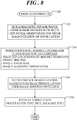
- FIG. 8 shows a flowchart of a fabrication process 250 in accordance with another embodiment.
- Fabrication process 250 is described in connection with the fabrication of magnetic field sensor package 70 ( FIG. 3 ) having three sense axes (e.g., X-axis, Y-axis, Z-axis magnetic field sensors 72, 74, 76).
- FIG. 3 should be viewed in concurrence with the fabrication methodology of FIG. 8 .
- fabrication process 250 may be readily adapted to produce a single or dual sense axis magnetic field sensor.
- fabrication process 250 is exemplary in nature. Thus, only the primary operations of fabrication process 250 are discussed herein for simplicity. Furthermore, the process blocks depicted in FIG. 8 may be performed in parallel with each other or with performing other processes, and each process block will include many separate process steps. In addition, it is to be understood that the particular ordering of the process blocks depicted in FIG. 8 may be modified while achieving substantially the same result. Accordingly, such modifications are intended to be included within the scope of the inventive subject matter.
- a magnetic sensor wafer is built, i.e., fabricated, utilizing known methodologies to produce a plurality of sensor bridges (e.g., Wheatstone bridges 94, 104, 114).
- sensor bridges e.g., Wheatstone bridges 94, 104, 114.
- Each of the sensors bridges are thus fabricated to include four sensor legs, with each sensor leg having one or more magnetoresistive sense elements, e.g., MTJ's.
- Fabrication of the magnetic sense wafer concurrently entails setting (i.e., self-biasing) the initial orientation of sense magnetization 204 of sense layer 198 of each of the magnetoresistive sense elements by building sense layer 198 to include ferromagnetic and non-magnetic layers, by "growing in” or otherwise treating sense layer 198, and/or by shape anisotropy so that sense magnetization 204 of sense layer 198, in the absence of an external magnetic field, will be in an out-of-plane direction relative to X-Y plane 80 ( FIG. 4 ) of magnetic field sensor package 70.
- one or more permanent magnet layers (e.g., first and second permanent magnet layers 206, 208 of FIG. 5 or single permanent magnet layer 244 of FIG. 7 ) is suitably formed for Z-axis magnetic field sensor 76 in order to magnetically bias sense magnetization 204, in the absence of Z-axis external magnetic field 40, in the out-of-plane first and second directions 216, 218 ( FIGs. 5 and 7 ) that is also non-perpendicular to X-Y plane 80 ( FIG. 4 ).
- Considerations for biasing sense magnetization 204 include selecting locations at which magnet segments 212, 214 ( FIG. 5 ) or magnet segments 248 ( FIG.
- the permanent magnet layer(s) may entail deposition, patterning, and etching of a suitable material to form the magnet segments.
- Such material may include iron, nickel, cobalt, some alloys of rare earth materials or an alloy comprising any one or a combination of these elements that is magnetized and creates its own persistent magnetic field.
- the permanent magnet layer(s) is formed from a magnetically "hard” material that is subjected to processing in a powerful magnetic field during manufacture to align its internal microcrystalline structure, so as to make it very difficult to demagnetize.
- reference magnetization 202 of pinned layers 196 of each of the magnetoresistive sense elements is set.
- a thermally assisted switching (TAS) process may be performed to set reference magnetization 202, as discussed above.
- four orientations of reference magnetization 202 may be set. Two orientations of reference magnetization 202 are aligned with X-axis 54, but are antiparallel relative to one another for X-axis magnetic field sensor. A single orientation of reference magnetization 202 is aligned with X-axis 54 for Z-axis magnetic field sensor 76. Additionally, two orientations of reference magnetization 202 are aligned with Y-axis 56, but are antiparallel relative to one another for Y-axis magnetic field sensor 74.
- fabrication of the magnetic sensor wafer continues with fabrication finalization processes such was wafer level testing, dicing, packaging, and the like. Thereafter, fabrication process 250 ends.
- embodiments disclosed herein entail a magnetic field sensor capable of sensing magnetic fields along one or more mutually exclusive sense axes, typically referred to as the X-axis, Y-axis, and Z-axis.
- An embodiment of a magnetic field sensor comprises a sensor bridge, the sensor bridge including a first sensor leg and a second sensor leg.
- a first magnetoresistive sense element is formed in the first leg and is located in a plane of the magnetic field sensor, the first magnetoresistive sense element having a first pinned layer and a first sense layer.
- a second magnetoresistive sense element formed in the second leg and located in the plane of the magnetic field sensor, the second magnetoresistive sense element having a second pinned layer and a second sense layer.
- the first and second magnetoresistive sense elements are sensitive to an external magnetic field along a sensing direction, wherein each of the first and second pinned layers has a reference magnetization oriented substantially parallel to the plane, and each of the first and second sense layers has a sense magnetization.
- a permanent magnet layer is spaced apart from the first and second magnetoresistive sense elements, wherein in the absence of the external magnetic field, the permanent magnet layer magnetically biases the sense magnetization in an out-of-plane orientation relative to the plane, the sense magnetization of the first sense layer being oriented in a first direction and the sense magnetization of the second sense layer being oriented in second direction that differs from the first direction.
- a sensor bridge configuration of magnetoresistive sense elements can be implemented for each sense axis.
- the sensor bridges incorporate multiple orientations of reference magnetization of the pinned layer, along with out-of-plane biasing of the sense layer for each of the magnetoresistive sense elements.
- one sensor bridge design is utilized for sensing an external magnetic field that is perpendicular to the plane of the magnetic field sensor package and includes at least one permanent magnetic layer with a single magnetization direction to enable sensing of the out-of-plane external magnetic field without the use of flux concentrators.
- the at least one permanent magnet layer is strategically patterned (shape and position) to generate two unique, in-plane external bias field vectors of the sense layer to allow a single sensor bridge to respond to the out-of-plane external magnetic field without inter-axis coupling of sensor response.
- the various inventive concepts and principles embodied herein enable an ultra low power, multiple sense axis magnetic field sensor without detrimental perming effects for improved sensitivity, reliability, and cost savings.
- a magnetic field sensor which comprises a sensor bridge, a first magnetoresistive sense element, a second magnetoresistive sense element and a permanent magnet layer.
- the sensor bridge includes a first sensor leg and a second sensor leg.
- the first magnetoresistive sense element is formed in the first leg and is located in a plane of the magnetic field sensor.
- the first magnetoresistive sense element has a first pinned layer and a first sense layer.
- the second magnetoresistive sense element is formed in the second leg and is located in the plane of the magnetic field sensor.
- the second magnetoresistive sense element has a second pinned layer and a second sense layer.
- the first and second magnetoresistive sense elements are sensitive to an external magnetic field along a sensing direction.
- Each of the first and second pinned layers has a reference magnetization oriented substantially parallel to the plane, and each of the first and second sense layers has a sense magnetization.
- the permanent magnet layer is spaced apart from the first and second magnetoresistive sense elements. In the absence of the external magnetic field, the permanent magnet layer magnetically biases the sense magnetization in an out-of-plane orientation relative to the plane, the sense magnetization of the first sense layer being oriented in a first direction and the sense magnetization of the second sense layer being oriented in second direction that differs from the first direction.
- the sense magnetization of the first sense layer of the first magnetoresistive sense element is orientable from the first direction toward or away from the plane of the magnetic field sensor in response to the external magnetic field.
- the sense magnetization of the first sense layer of the first magnetoresistive sense element is orientable from the second direction toward or away from the plane of the magnetic field sensor in response to the external magnetic field.
- the out-of-plane orientation of the sense magnetization of each of the first and second sense layers is non-perpendicular to the plane of the magnetic field sensor.
- each of the first and second directions of the sense magnetization of the first and second magnetoresistive sense elements is tilted below the plane of the magnetic field sensor by an equivalent angular magnitude.
- the second direction is coplanar with the first direction in the out-of-plane orientation.
- the external magnetic field is perpendicular to the plane of the magnetic field sensor, and inclusion of the permanent magnet layer enables detection of the external magnetic field in the sensing direction that is also perpendicular to the plane of the magnetic field sensor.
- the permanent magnet layer is characterized by a single magnetic orientation.
- the single magnetic orientation is substantially perpendicular to the magnetic field sensor.
- the single magnetic orientation is substantially parallel to the magnetic field sensor.
- each of the first and second magnetoresistive sense elements is characterized by a central axis.
- the central axis distinguishes a first side of the each of the first and second magnetoresistive sense elements from a second side of the each of the first and second magnetoresistive sense elements.
- the permanent magnet layer comprises a first magnet segment and a second magnet segment. The first magnet segment is positioned closer to the second side of the first magnetoresistive sense element than to the first side of the first magnetoresistive sense element to orient the first sense layer in the first direction, and the second magnet segment being positioned closer to the first side of the second magnetoresistive sense element than to the second side of the second magnetoresistive sense element to orient the second sense layer in the second direction.
- the permanent magnet layer is a first permanent magnet layer and the magnetic field sensor further comprises a second permanent magnet layer vertically displaced away from the first permanent magnet layer.
- the first and second magnetoresistive sense elements are interposed between the first and second permanent magnet layers, and the first and second permanent magnet layers function cooperatively to magnetically bias the sense magnetization of the first and second magnetoresistive sense elements in the out-of-plane orientation relative to the plane.
- reference magnetization of each of the first and second pinned layers is oriented in the same direction substantially parallel to the plane.
- the sensor bridge further comprises a third sensor leg and a fourth sensor leg.
- the third sensor leg has a third magnetoresistive sense element formed therein.
- the third magnetoresistive sense element has a third pinned layer and a third sense layer.
- the fourth sensor leg has a fourth magnetoresistive sense element formed therein.
- the fourth magnetoresistive sense element has a fourth pinned layer and a fourth sense layer.
- the first, second, third, and fourth sensor legs are coupled as a Wheatstone bridge such that the first and fourth magnetoresistive sense elements are coupled in series to form a first half of the Wheatstone bridge.
- the second and third magnetoresistive sense elements are coupled in series to form a second half of the Wheatstone bridge.
- the first half of the Wheatstone bridge is coupled in parallel with the second half of the Wheatstone bridge such that a first junction of the first and second magnetoresistive sense elements forms a first input terminal and a second junction of the third and fourth magnetoresistive sense elements forms a second input terminal.
- the reference magnetization of each of the first, second, third, and fourth pinned layers of each of the first and third magnetoresistive sense elements is oriented in the same direction substantially parallel to the plane.
- the permanent magnet layer is spaced apart from the third and fourth magnetoresistive sense elements, the permanent magnet layer magnetically biasing the sense magnetization of the third sense layer in the first direction and magnetically biasing the sense magnetization of the fourth sense layer in the second direction.
- a magnetic field sensor which comprises a sensor bridge, a first magnetoresistive sense element, a second magnetoresistive sense element and a permanent magnet layer.
- the sensor bridge includes a first sensor leg and a second sensor leg.
- the first magnetoresistive sense element is formed in the first leg and is located in a plane of the magnetic field sensor.
- the first magnetoresistive sense element has a first pinned layer and a first sense layer.
- the second magnetoresistive sense element is formed in the second leg and is located in the plane of the magnetic field sensor.
- the second magnetoresistive sense element has a second pinned layer and a second sense layer.
- the first and second magnetoresistive sense elements are sensitive to an external magnetic field along a sensing direction.
- Each of the first and second pinned layers has a reference magnetization oriented substantially parallel to the plane, and each of the first and second sense layers has a sense magnetization.
- the permanent magnet layer is spaced apart from the first and second magnetoresistive sense elements. In the absence of the external magnetic field, the permanent magnet layer magnetically biases the sense magnetization in an out-of-plane orientation relative to the plane, the out-of-plane orientation of each of the first and second sense layers is non-perpendicular to the plane of the magnetic field sensor, the sense magnetization of the first sense layer being oriented in a first direction and the sense magnetization of the second sense layer being oriented in second direction that differs from the first direction, and the second direction being coplanar with the first direction.
- the sense magnetization of the first sense layer of the first magnetoresistive sense element is orientable from the first direction toward or away from the plane of the magnetic field sensor in response to the external magnetic field.
- the sense magnetization of the first sense layer of the first magnetoresistive sense element is orientable from the second direction toward or away from the plane of the magnetic field sensor in response to the external magnetic field.
- each of the first and second directions of the sense magnetization of the first and second magnetoresistive sense elements is tilted below the plane of the magnetic field sensor by an equivalent angular magnitude.
- the external magnetic field is perpendicular to the plane of the magnetic field sensor, and inclusion of the permanent magnet layer enables detection of the external magnetic field in the sensing direction that is also perpendicular to the plane of the magnetic field sensor.
- a magnetic field sensor which comprises a sensor bridge, a first magnetoresistive sense element, a second magnetoresistive sense element and a permanent magnet layer.
- the sensor bridge includes a first sensor leg and a second sensor leg.
- the first magnetoresistive sense element is formed in the first leg and located in a plane of the magnetic field sensor, the first magnetoresistive sense element having a first pinned layer and a first sense layer.
- the second magnetoresistive sense element is formed in the second leg and located in the plane of the magnetic field sensor.
- the second magnetoresistive sense element has a second pinned layer and a second sense layer.
- the first and second magnetoresistive sense elements are sensitive to an external magnetic field along a sensing direction.
- Each of the first and second pinned layers has a reference magnetization oriented substantially parallel to the plane, and each of the first and second sense layers has a sense magnetization.
- the reference magnetization of each of the first and second pinned layers is oriented in the same direction substantially parallel to the plane.
- the permanent magnet layer is spaced apart from the first and second magnetoresistive sense elements.
- the permanent magnet layer magnetically biases the sense magnetization in an out-of-plane orientat ion relative to the plane, the out-of-plane orientation of the sense magnetization of each of the first and second sense layers being non-perpendicular to the plane of the magnetic field sensor, the sense magnetization of the first sense layer being oriented in a first direction and the sense magnetization of the second sense layer being oriented in second direction that differs from the first direction.
- each of the first and second directions of the sense magnetization of the first and second magnetoresistive sense elements is tilted below the plane of the magnetic field sensor by an equivalent angular magnitude.
- the sensor bridge further comprises a third sensor leg and a fourth sensor leg.
- the third sensor leg has a third magnetoresistive sense element formed therein, the third magnetoresistive sense element having a third pinned layer and a third sense layer.
- the fourth sensor leg has a fourth magnetoresistive sense element formed therein.
- the fourth magnetoresistive sense element has a fourth pinned layer and a fourth sense layer.
- the first, second, third, and fourth sensor legs are coupled as a Wheatstone bridge such that the first and fourth magnetoresistive sense elements are coupled in series to form a first half of the Wheatstone bridge.
- the second and third magnetoresistive sense elements are coupled in series to form a second half of the Wheatstone bridge.
- the first half of the Wheatstone bridge is coupled in parallel with the second half of the Wheatstone bridge such that a first junction of the first and second magnetoresistive sense elements forms a first input terminal and a second junction of the third and fourth magnetoresistive sense elements forms a second input terminal.
- the reference magnetization of each of the first, second, third, and fourth pinned layers of each of the first and third magnetoresistive sense elements is oriented in the same direction substantially parallel to the plane.
- the permanent magnet layer is spaced apart from the third and fourth magnetoresistive sense elements. The permanent magnet layer magnetically biases the sense magnetization of the third sense layer in the first direction and magnetically biasing the sense magnetization of the fourth sense layer in the second direction.
Landscapes
- Physics & Mathematics (AREA)
- General Physics & Mathematics (AREA)
- Condensed Matter Physics & Semiconductors (AREA)
- Measuring Magnetic Variables (AREA)
Claims (10)
- Magnetfeldsensor mit:einer Sensorbrücke (114), wobei die Sensorbrücke (114) einen ersten Sensorschenkel (116) und einen zweiten Sensorschenkel (118) aufweist;einem ersten magnetoresistiven Erfassungselement (172), das in dem ersten Sensorschenkel (116) ausgebildet und in einer Ebene (80) des Magnetfeldsensors (70, 72, 74, 76) angeordnet ist, wobei das erste magnetoresistive Erfassungselement (172) eine erste festgelegte Schicht (196) und eine erste Erfassungsschicht (198) hat;einem zweiten magnetoresistiven Erfassungselement (174), das in dem zweiten Sensorschenkel (118) ausgebildet und in der Ebene (80) des Magnetfeldsensors (70, 72, 74, 76) angeordnet ist, wobei das zweite magnetoresistive Erfassungselement (174) eine zweite festgelegte Schicht (196) und eine zweite Erfassungsschicht (198) hat, wobei das erste und das zweite magnetoresistive Erfassungselement (172, 174) auf ein externes Magnetfeld (38, 82, 40) entlang einer Erfassungsrichtung empfindlich sind, wobei die erste und die zweite festgelegte Schicht (196) jeweils eine Referenzmagnetisierung (202) haben, die im Wesentlichen parallel zu der Ebene (80) orientiert ist, und wobei die erste und die zweite Erfassungsschicht (196, 198) jeweils eine Erfassungsmagnetisierung (204) haben;einer ersten Dauermagnetschicht (206), die von dem ersten und dem zweiten magnetoresistiven Erfassungselement (172, 174) räumlich beabstandet ist, wobei beim Fehlen des externen Magnetfeldes (38, 82, 40) die erste Dauermagnetschicht (206) die Erfassungsmagnetisierung (204) in einer Orientierung außerhalb der Ebene bezüglich der Ebene (80) magnetisch vorspannt, und wobei die Erfassungsmagnetisierung (204) der ersten Erfassungsschicht (198) in einer ersten Richtung (216) orientiert ist und die Erfassungsmagnetisierung (204) der zweiten Erfassungsschicht (198) in einer zweiten Richtung (218) orientiert ist, die sich von der ersten Richtung (216) unterscheidet; undeiner zweiten Dauermagnetschicht (208), die von der ersten Dauermagnetschicht (206) vertikal versetzt ist, wobei das erste und das zweite magnetoresistive Erfassungselement (172, 174) zwischen der ersten und der zweiten Dauermagnetschicht (206, 208) angeordnet sind, und wobei die erste und die zweite Dauermagnetschicht (206, 208) zusammenwirken, um die Erfassungsmagnetisierung (204) des ersten und des zweiten magnetoresistiven Erfassungselements (172, 174) in der Orientierung außerhalb der Ebene bezüglich der Ebene (80) magnetisch vorzuspannen,dadurch gekennzeichnet, dass die erste und die zweite Dauermagnetschicht (206, 208) eine einzige magnetische Orientierung (232) im Wesentlichen senkrecht zu der Ebene (80) haben.
- Magnetfeldsensor gemäß Anspruch 1, wobei:die Erfassungsmagnetisierung (204) der ersten Erfassungsschicht (198) des ersten magnetoresistivem Erfassungselements (172) aus der ersten Richtung (216) zu der Ebene (80) des Magnetfeldsensors (70, 72, 74, 76) als Reaktion auf das externe Magnetfeld (38, 82, 40) hin oder von dieser weg orientierbar ist; unddie Erfassungsmagnetisierung (204) der ersten Erfassungsschicht (198) des ersten magnetoresistiven Erfassungselements (172) aus der zweiten Richtung (218) zu der Ebene (80) des Magnetfeldsensors (70, 72, 74, 76) als Reaktion auf das externe Magnetfeld (38, 82, 40) hin oder von dieser weg orientierbar ist.
- Magnetfeldsensor gemäß Anspruch 1 oder Anspruch 2, wobei beim Fehlen des externen Magnetfelds (38, 82, 40) die Orientierung außerhalb der Ebene der Erfassungsmagnetisierung (204) der ersten und der zweiten Erfassungsschicht (196, 198) jeweils nicht senkrecht zu der Ebene (80) des Magnetfeldsensors (70, 72, 74, 76) ist.
- Magnetfeldsensor gemäß einem der Ansprüche 1 bis 3, wobei die erste und die zweite Richtung (216, 218) der Erfassungsmagnetisierung (204) des ersten und des zweiten magnetoresistiven Erfassungselements (172, 174) jeweils unterhalb der Ebene (80) des Magnetfeldsensors (70, 72, 74, 76) durch eine äquivalente Winkelgröße geneigt ist.
- Magnetfeldsensor gemäß einem der Ansprüche 1 bis 4, wobei die zweite Richtung (218) koplanar mit der ersten Richtung (216) in der Orientierung außerhalb der Ebene ist.
- Magnetfeldsensor gemäß einem der Ansprüche 1 bis 5, wobei das externe Magnetfeld (38, 82, 40) senkrecht zu der Ebene (80) des Magnetfeldsensors (70, 72, 74, 76) ist, und wobei ein Einschluss der ersten und der zweiten Dauermagnetschicht (206, 208) eine Erfassung des externen Magnetfelds (38, 82, 40) in der Erfassungsrichtung ermöglicht, die ebenfalls senkrecht zu der Ebene (80) des Magnetfeldsensors (70, 72, 74, 76) ist.
- Magnetfeldsensor gemäß einem der Ansprüche 1 bis 6, wobei die einzige magnetische Orientierung (232) im Wesentlichen senkrecht zu dem Magnetfeldsensor (70, 72, 74, 76) ist.
- Magnetfeldsensor gemäß einem der Ansprüche 1 bis 7, wobei die einzige magnetische Orientierung (232) im Wesentlichen parallel zu dem Magnetfeldsensor (70, 72, 74, 76) ist.
- Magnetfeldsensor gemäß einem der Ansprüche 1 bis 8, wobei die Referenzmagnetisierung (202) der ersten und der zweiten festgelegten Schicht (196) jeweils in derselben Richtung im Wesentlichen parallel zu der Ebene (80) orientiert ist.
- Magnetfeldsensor gemäß einem der Ansprüche 1 bis 9, wobei die Sensorbrücke (114) des Weiteren Folgendes aufweist:einen dritten Sensorschenkel (120), der ein darin ausgebildetes drittes magnetoresistives Erfassungselement (176) hat, wobei das dritte magnetoresistive Erfassungselement eine dritte festgelegte Schicht (196) und eine dritte Erfassungsschicht (198) hat; undeinen vierten Sensorschenkel (122) mit einem darin ausgebildeten vierten magnetoresistiven Erfassungselement (178), wobei das vierte magnetoresistive Erfassungselement eine vierte festgelegte Schicht (196) und eine vierte Erfassungsschicht (198) hat, wobei:der erste, der zweite, der dritte und der vierte Sensorschenkel (116 - 122) als eine Wheatstone-Brücke (114) derart gekoppelt sind, dass das erste und das vierte magnetoresistive Erfassungselement (172, 178) in Reihe gekoppelt sind, um eine erste Hälfte der Wheatstone-Brücke (114) zu bilden, wobei das zweite und das dritte magnetoresistive Erfassungselement (147, 176) in Reihe gekoppelt sind, um eine zweite Hälfte der Wheatstone-Brücke (114) zu bilden, wobei die erste Hälfte der Wheatstone-Brücke (114) parallel mit der zweiten Hälfte der Wheatstone-Brücke (114) derart gekoppelt ist, dass eine erste Verbindung (180) des ersten und des zweiten magnetoresistiven Erfassungselements (172, 174) einen ersten Eingangsanschluss (182) bildet und dass eine zweite Verbindung (184) des dritten und des vierten magnetoresistiven Erfassungselements einen zweiten Eingangsanschluss (186) bildet;wobei die Referenzmagnetisierung (202) der ersten, der zweiten, der dritten und der vierten festgelegten Schicht (196) des jeweiligen ersten und dritten magnetoresistiven Erfassungselements (172, 176) jeweils in derselben Richtung im Wesentlichen parallel zu der Ebene (80) orientiert ist; undwobei die erste Dauermagnetschicht (206) von dem dritten und dem vierten magnetoresistiven Erfassungselement (176, 178) räumlich beabstandet ist, wobei die erste Dauermagnetschicht (206) die Erfassungsmagnetisierung (204) der dritten Erfassungsschicht (198) in der ersten Richtung (216) magnetisch vorspannt und die Erfassungsmagnetisierung (204) der vierten Erfassungsschicht (198) in der zweiten Richtung (218) magnetisch vorspannt.
Applications Claiming Priority (1)
| Application Number | Priority Date | Filing Date | Title |
|---|---|---|---|
| US15/006,911 US9841469B2 (en) | 2016-01-26 | 2016-01-26 | Magnetic field sensor with multiple sense layer magnetization orientations |
Publications (2)
| Publication Number | Publication Date |
|---|---|
| EP3199963A1 EP3199963A1 (de) | 2017-08-02 |
| EP3199963B1 true EP3199963B1 (de) | 2018-06-27 |
Family
ID=57906552
Family Applications (1)
| Application Number | Title | Priority Date | Filing Date |
|---|---|---|---|
| EP17153302.9A Active EP3199963B1 (de) | 2016-01-26 | 2017-01-26 | Magnetfeldsensor mit mehreren messschichtmagnetisierungsausrichtungen |
Country Status (2)
| Country | Link |
|---|---|
| US (1) | US9841469B2 (de) |
| EP (1) | EP3199963B1 (de) |
Families Citing this family (13)
| Publication number | Priority date | Publication date | Assignee | Title |
|---|---|---|---|---|
| US9897667B2 (en) | 2016-01-26 | 2018-02-20 | Nxp Usa, Inc. | Magnetic field sensor with permanent magnet biasing |
| US10545196B2 (en) | 2016-03-24 | 2020-01-28 | Nxp Usa, Inc. | Multiple axis magnetic sensor |
| US10145907B2 (en) | 2016-04-07 | 2018-12-04 | Nxp Usa, Inc. | Magnetic field sensor with permanent magnet biasing |
| US9933496B2 (en) | 2016-04-21 | 2018-04-03 | Nxp Usa, Inc. | Magnetic field sensor with multiple axis sense capability |
| JP6745774B2 (ja) * | 2017-09-20 | 2020-08-26 | 株式会社東芝 | センサ及び電子機器 |
| US11835601B2 (en) * | 2017-12-21 | 2023-12-05 | Robert Bosch Gmbh | Magnetoresistive magnetic field sensor bridge with compensated cross-axis effect |
| US10509082B2 (en) * | 2018-02-08 | 2019-12-17 | Nxp B.V. | Magnetoresistive sensor systems with stray field cancellation utilizing auxiliary sensor signals |
| US11513175B2 (en) * | 2020-02-11 | 2022-11-29 | Globalfoundries Singapore Pte. Ltd. | Tunnel magnetoresistance sensor devices and methods of forming the same |
| JP7215454B2 (ja) * | 2020-04-08 | 2023-01-31 | Tdk株式会社 | 磁気センサ、磁気式エンコーダおよびレンズ位置検出装置 |
| EP3992655A1 (de) * | 2020-11-03 | 2022-05-04 | Crocus Technology S.A. | Magnetoresistives sensorelement mit breitem linearen ansprechverhalten und robuster nominaler leistung und herstellungsverfahren dafür |
| JP7284201B2 (ja) * | 2021-02-12 | 2023-05-30 | Tdk株式会社 | 磁気センサ、位置検出装置及び電子機器 |
| US11747412B2 (en) * | 2021-09-08 | 2023-09-05 | Globalfoundries Singapore Pte. Ltd. | Magnetic field sensor using magnetic tunneling junction (MTJ) structures and passive resistors |
| CN120693053A (zh) * | 2025-06-27 | 2025-09-23 | 珠海多创科技有限公司 | 一种磁阻元件、角度传感器及电子设备 |
Family Cites Families (44)
| Publication number | Priority date | Publication date | Assignee | Title |
|---|---|---|---|---|
| SG47479A1 (en) | 1992-08-25 | 1998-04-17 | Seagate Technology | A magnetoresistive sensor and method of making the same |
| JP3210192B2 (ja) | 1994-09-29 | 2001-09-17 | アルプス電気株式会社 | 磁気検出素子 |
| US6501678B1 (en) | 1999-06-18 | 2002-12-31 | Koninklijke Philips Electronics N.V. | Magnetic systems with irreversible characteristics and a method of manufacturing and repairing and operating such systems |
| DE10028640B4 (de) | 2000-06-09 | 2005-11-03 | Institut für Physikalische Hochtechnologie e.V. | Wheatstonebrücke, beinhaltend Brückenelemente, bestehend aus einem Spin-Valve-System, sowie ein Verfahren zu deren Herstellung |
| JP3498737B2 (ja) | 2001-01-24 | 2004-02-16 | ヤマハ株式会社 | 磁気センサの製造方法 |
| US7054114B2 (en) | 2002-11-15 | 2006-05-30 | Nve Corporation | Two-axis magnetic field sensor |
| TWI361503B (en) | 2005-03-17 | 2012-04-01 | Yamaha Corp | Three-axis magnetic sensor and manufacturing method therefor |
| WO2008020817A1 (en) | 2006-08-17 | 2008-02-21 | Agency For Science, Technology And Research | Read head and magnetic device comprising the same |
| US7729093B1 (en) | 2006-09-28 | 2010-06-01 | Headway Technologies, Inc. | Detection of magnetic beads using a magnetoresistive device together with ferromagnetic resonance |
| JP5152495B2 (ja) | 2008-03-18 | 2013-02-27 | 株式会社リコー | 磁気センサーおよび携帯情報端末装置 |
| US7965077B2 (en) | 2008-05-08 | 2011-06-21 | Everspin Technologies, Inc. | Two-axis magnetic field sensor with multiple pinning directions |
| US8269486B2 (en) | 2008-11-12 | 2012-09-18 | Infineon Technologies Ag | Magnetic sensor system and method |
| US8553449B2 (en) | 2009-01-09 | 2013-10-08 | Micron Technology, Inc. | STT-MRAM cell structures |
| US8257596B2 (en) | 2009-04-30 | 2012-09-04 | Everspin Technologies, Inc. | Two-axis magnetic field sensor with substantially orthogonal pinning directions |
| US8390283B2 (en) | 2009-09-25 | 2013-03-05 | Everspin Technologies, Inc. | Three axis magnetic field sensor |
| US8582250B2 (en) | 2009-12-04 | 2013-11-12 | Seagate Technology Llc | Double biasing for trilayer MR sensors |
| US8518734B2 (en) | 2010-03-31 | 2013-08-27 | Everspin Technologies, Inc. | Process integration of a single chip three axis magnetic field sensor |
| CN102280574B (zh) | 2011-01-07 | 2014-04-16 | 江苏多维科技有限公司 | 薄膜磁电阻传感元件、多个传感元件的组合及与该组合耦合的电子装置 |
| US8901924B2 (en) * | 2011-02-21 | 2014-12-02 | Everspin Technologies, Inc. | Apparatus and method for sequentially resetting elements of a magnetic sensor array |
| CN102226835A (zh) | 2011-04-06 | 2011-10-26 | 江苏多维科技有限公司 | 单一芯片双轴磁场传感器及其制备方法 |
| CN102226836A (zh) | 2011-04-06 | 2011-10-26 | 江苏多维科技有限公司 | 单一芯片桥式磁场传感器及其制备方法 |
| CN202013413U (zh) | 2011-04-06 | 2011-10-19 | 江苏多维科技有限公司 | 单一芯片桥式磁场传感器 |
| US8922950B2 (en) | 2011-05-06 | 2014-12-30 | Seagate Technology Llc | Multi-layer magnetoresistive shield with transition metal layer |
| US8730673B2 (en) | 2011-05-27 | 2014-05-20 | Lockheed Martin Corporation | Fluid-cooled module for integrated circuit devices |
| CN102385043B (zh) | 2011-08-30 | 2013-08-21 | 江苏多维科技有限公司 | Mtj三轴磁场传感器及其封装方法 |
| CN102426344B (zh) | 2011-08-30 | 2013-08-21 | 江苏多维科技有限公司 | 三轴磁场传感器 |
| CN103987654A (zh) | 2011-10-19 | 2014-08-13 | 明尼苏达大学董事会 | 用于高吞吐量生物分子测试的磁性生物医学传感器和感测系统 |
| CN102419393B (zh) | 2011-12-30 | 2013-09-04 | 江苏多维科技有限公司 | 一种电流传感器 |
| CN102565727B (zh) | 2012-02-20 | 2016-01-20 | 江苏多维科技有限公司 | 用于测量磁场的磁电阻传感器 |
| TWI431301B (zh) * | 2012-03-05 | 2014-03-21 | Ind Tech Res Inst | 應用穿隧式磁電阻器之磁場感測方法及磁場感測裝置 |
| US9279865B2 (en) | 2012-05-09 | 2016-03-08 | Everspin Technologies, Inc. | Method and structure for testing and calibrating three axis magnetic field sensing devices |
| CN102809665B (zh) | 2012-06-04 | 2016-08-03 | 江苏多维科技有限公司 | 一种磁电阻齿轮传感器 |
| US9316706B2 (en) | 2012-06-11 | 2016-04-19 | Infineon Technologies Ag | Minimum magnetic field detection systems and methods in magnetoresistive sensors |
| WO2014025914A1 (en) | 2012-08-07 | 2014-02-13 | The Regents Of The University Of California | Magnetoresistance sensor with perpendicular anisotropy |
| US20150309125A1 (en) | 2013-04-29 | 2015-10-29 | Labsys Llc | Monolithic Three-Axis Magnetometer |
| EP2860542B1 (de) | 2013-10-11 | 2016-04-20 | Crocus Technology S.A. | Verfahren zur Messung dreidimensionaler Magnetfelder |
| EP2860543B1 (de) | 2013-10-11 | 2016-04-20 | Crocus Technology S.A. | Magnetische Sensorzelle zur Messung dreidimensionaler Magnetfelder |
| US20150191560A1 (en) | 2014-01-08 | 2015-07-09 | E I Du Pont De Nemours And Company | Thickened compositions comprising crosslinked polymers containing biomass derived materials |
| CN103954920B (zh) | 2014-04-17 | 2016-09-14 | 江苏多维科技有限公司 | 一种单芯片三轴线性磁传感器及其制备方法 |
| US9720051B2 (en) | 2014-05-29 | 2017-08-01 | Nxp Usa, Inc. | Sensor package including a magnetic field sensor and a continuous coil structure for enabling z-axis self-test capability |
| US9739842B2 (en) | 2016-01-26 | 2017-08-22 | Nxp Usa, Inc. | Magnetic field sensor with skewed sense magnetization of sense layer |
| US9897667B2 (en) | 2016-01-26 | 2018-02-20 | Nxp Usa, Inc. | Magnetic field sensor with permanent magnet biasing |
| US10545196B2 (en) | 2016-03-24 | 2020-01-28 | Nxp Usa, Inc. | Multiple axis magnetic sensor |
| US10145907B2 (en) | 2016-04-07 | 2018-12-04 | Nxp Usa, Inc. | Magnetic field sensor with permanent magnet biasing |
-
2016
- 2016-01-26 US US15/006,911 patent/US9841469B2/en not_active Expired - Fee Related
-
2017
- 2017-01-26 EP EP17153302.9A patent/EP3199963B1/de active Active
Non-Patent Citations (1)
| Title |
|---|
| None * |
Also Published As
| Publication number | Publication date |
|---|---|
| EP3199963A1 (de) | 2017-08-02 |
| US20170212175A1 (en) | 2017-07-27 |
| US9841469B2 (en) | 2017-12-12 |
Similar Documents
| Publication | Publication Date | Title |
|---|---|---|
| EP3199963B1 (de) | Magnetfeldsensor mit mehreren messschichtmagnetisierungsausrichtungen | |
| EP3199964B1 (de) | Magnetfeldsensor mit dauermagnetvorspannung | |
| EP3208626B1 (de) | Magnetfeldsensor mit geneigter messmagnetisierung einer messschicht | |
| EP3223028B1 (de) | Mehrfachachsenmagnetsensor | |
| EP3229035B1 (de) | Magnetfeldsensor mit dauermagnetvorspannung | |
| US10734443B2 (en) | Dual manetoresistance element with two directions of response to external magnetic fields | |
| CN103081008B (zh) | 对于零偏移具有降低的补偿角的二轴磁场传感器 | |
| JP4557134B2 (ja) | 磁気センサの製造方法、同磁気センサの製造方法に使用されるマグネットアレイ及び同マグネットアレイの製造方法 | |
| JP5297539B2 (ja) | 磁気センサ | |
| US20200064413A1 (en) | Magnetoresistance element with perpendicular or parallel magnetic anistropy | |
| JP2004163419A (ja) | 磁気センサ、同磁気センサの製造方法及び同製造方法に適したマグネットアレイ | |
| EP3236276B1 (de) | Magnetfeldsensor mit mehrachsiger erfassungsfähigkeit | |
| JP2008286739A (ja) | 磁界検出器及び回転角度検出装置 | |
| JP2009175120A (ja) | 磁気センサ及び磁気センサモジュール | |
| JP2003008101A (ja) | トンネル磁気抵抗効果素子及びこの素子を用いた方位検知システム | |
| TW201327956A (zh) | 磁感應器 | |
| JP4331630B2 (ja) | 磁気センサ | |
| JP4575602B2 (ja) | 磁気検知素子 | |
| JP2003167039A (ja) | 磁気センサ及びこの磁気センサを用いた方位検知システム | |
| JP3835445B2 (ja) | 磁気センサ | |
| US20260128202A1 (en) | Method for manufacturing magnetic laminated body and magnetic sensor, and apparatus for manufacturing magnetic laminated body | |
| JP4954317B2 (ja) | 磁気検知素子及びこの素子を用いた方位検知システム | |
| JP2004165333A (ja) | 磁気センサ、この磁気センサを用いた方位検知システム及び携帯通信端末 | |
| JP2003318466A (ja) | 磁気センサ、この磁気センサを用いた方位検知システム及び携帯通信端末 |
Legal Events
| Date | Code | Title | Description |
|---|---|---|---|
| PUAI | Public reference made under article 153(3) epc to a published international application that has entered the european phase |
Free format text: ORIGINAL CODE: 0009012 |
|
| STAA | Information on the status of an ep patent application or granted ep patent |
Free format text: STATUS: THE APPLICATION HAS BEEN PUBLISHED |
|
| AK | Designated contracting states |
Kind code of ref document: A1 Designated state(s): AL AT BE BG CH CY CZ DE DK EE ES FI FR GB GR HR HU IE IS IT LI LT LU LV MC MK MT NL NO PL PT RO RS SE SI SK SM TR |
|
| AX | Request for extension of the european patent |
Extension state: BA ME |
|
| STAA | Information on the status of an ep patent application or granted ep patent |
Free format text: STATUS: REQUEST FOR EXAMINATION WAS MADE |
|
| 17P | Request for examination filed |
Effective date: 20180202 |
|
| RBV | Designated contracting states (corrected) |
Designated state(s): AL AT BE BG CH CY CZ DE DK EE ES FI FR GB GR HR HU IE IS IT LI LT LU LV MC MK MT NL NO PL PT RO RS SE SI SK SM TR |
|
| GRAP | Despatch of communication of intention to grant a patent |
Free format text: ORIGINAL CODE: EPIDOSNIGR1 |
|
| STAA | Information on the status of an ep patent application or granted ep patent |
Free format text: STATUS: GRANT OF PATENT IS INTENDED |
|
| INTG | Intention to grant announced |
Effective date: 20180316 |
|
| GRAS | Grant fee paid |
Free format text: ORIGINAL CODE: EPIDOSNIGR3 |
|
| GRAA | (expected) grant |
Free format text: ORIGINAL CODE: 0009210 |
|
| STAA | Information on the status of an ep patent application or granted ep patent |
Free format text: STATUS: THE PATENT HAS BEEN GRANTED |
|
| AK | Designated contracting states |
Kind code of ref document: B1 Designated state(s): AL AT BE BG CH CY CZ DE DK EE ES FI FR GB GR HR HU IE IS IT LI LT LU LV MC MK MT NL NO PL PT RO RS SE SI SK SM TR |
|
| REG | Reference to a national code |
Ref country code: GB Ref legal event code: FG4D |
|
| REG | Reference to a national code |
Ref country code: AT Ref legal event code: REF Ref document number: 1012793 Country of ref document: AT Kind code of ref document: T Effective date: 20180715 |
|
| REG | Reference to a national code |
Ref country code: IE Ref legal event code: FG4D |
|
| REG | Reference to a national code |
Ref country code: DE Ref legal event code: R096 Ref document number: 602017000122 Country of ref document: DE |
|
| PG25 | Lapsed in a contracting state [announced via postgrant information from national office to epo] |
Ref country code: LT Free format text: LAPSE BECAUSE OF FAILURE TO SUBMIT A TRANSLATION OF THE DESCRIPTION OR TO PAY THE FEE WITHIN THE PRESCRIBED TIME-LIMIT Effective date: 20180627 Ref country code: FI Free format text: LAPSE BECAUSE OF FAILURE TO SUBMIT A TRANSLATION OF THE DESCRIPTION OR TO PAY THE FEE WITHIN THE PRESCRIBED TIME-LIMIT Effective date: 20180627 Ref country code: NO Free format text: LAPSE BECAUSE OF FAILURE TO SUBMIT A TRANSLATION OF THE DESCRIPTION OR TO PAY THE FEE WITHIN THE PRESCRIBED TIME-LIMIT Effective date: 20180927 Ref country code: SE Free format text: LAPSE BECAUSE OF FAILURE TO SUBMIT A TRANSLATION OF THE DESCRIPTION OR TO PAY THE FEE WITHIN THE PRESCRIBED TIME-LIMIT Effective date: 20180627 Ref country code: BG Free format text: LAPSE BECAUSE OF FAILURE TO SUBMIT A TRANSLATION OF THE DESCRIPTION OR TO PAY THE FEE WITHIN THE PRESCRIBED TIME-LIMIT Effective date: 20180927 |
|
| REG | Reference to a national code |
Ref country code: NL Ref legal event code: MP Effective date: 20180627 |
|
| REG | Reference to a national code |
Ref country code: LT Ref legal event code: MG4D |
|
| PG25 | Lapsed in a contracting state [announced via postgrant information from national office to epo] |
Ref country code: RS Free format text: LAPSE BECAUSE OF FAILURE TO SUBMIT A TRANSLATION OF THE DESCRIPTION OR TO PAY THE FEE WITHIN THE PRESCRIBED TIME-LIMIT Effective date: 20180627 Ref country code: GR Free format text: LAPSE BECAUSE OF FAILURE TO SUBMIT A TRANSLATION OF THE DESCRIPTION OR TO PAY THE FEE WITHIN THE PRESCRIBED TIME-LIMIT Effective date: 20180928 Ref country code: LV Free format text: LAPSE BECAUSE OF FAILURE TO SUBMIT A TRANSLATION OF THE DESCRIPTION OR TO PAY THE FEE WITHIN THE PRESCRIBED TIME-LIMIT Effective date: 20180627 Ref country code: HR Free format text: LAPSE BECAUSE OF FAILURE TO SUBMIT A TRANSLATION OF THE DESCRIPTION OR TO PAY THE FEE WITHIN THE PRESCRIBED TIME-LIMIT Effective date: 20180627 |
|
| REG | Reference to a national code |
Ref country code: AT Ref legal event code: MK05 Ref document number: 1012793 Country of ref document: AT Kind code of ref document: T Effective date: 20180627 |
|
| PG25 | Lapsed in a contracting state [announced via postgrant information from national office to epo] |
Ref country code: NL Free format text: LAPSE BECAUSE OF FAILURE TO SUBMIT A TRANSLATION OF THE DESCRIPTION OR TO PAY THE FEE WITHIN THE PRESCRIBED TIME-LIMIT Effective date: 20180627 |
|
| PG25 | Lapsed in a contracting state [announced via postgrant information from national office to epo] |
Ref country code: SK Free format text: LAPSE BECAUSE OF FAILURE TO SUBMIT A TRANSLATION OF THE DESCRIPTION OR TO PAY THE FEE WITHIN THE PRESCRIBED TIME-LIMIT Effective date: 20180627 Ref country code: CZ Free format text: LAPSE BECAUSE OF FAILURE TO SUBMIT A TRANSLATION OF THE DESCRIPTION OR TO PAY THE FEE WITHIN THE PRESCRIBED TIME-LIMIT Effective date: 20180627 Ref country code: IS Free format text: LAPSE BECAUSE OF FAILURE TO SUBMIT A TRANSLATION OF THE DESCRIPTION OR TO PAY THE FEE WITHIN THE PRESCRIBED TIME-LIMIT Effective date: 20181027 Ref country code: RO Free format text: LAPSE BECAUSE OF FAILURE TO SUBMIT A TRANSLATION OF THE DESCRIPTION OR TO PAY THE FEE WITHIN THE PRESCRIBED TIME-LIMIT Effective date: 20180627 Ref country code: AT Free format text: LAPSE BECAUSE OF FAILURE TO SUBMIT A TRANSLATION OF THE DESCRIPTION OR TO PAY THE FEE WITHIN THE PRESCRIBED TIME-LIMIT Effective date: 20180627 Ref country code: PL Free format text: LAPSE BECAUSE OF FAILURE TO SUBMIT A TRANSLATION OF THE DESCRIPTION OR TO PAY THE FEE WITHIN THE PRESCRIBED TIME-LIMIT Effective date: 20180627 Ref country code: EE Free format text: LAPSE BECAUSE OF FAILURE TO SUBMIT A TRANSLATION OF THE DESCRIPTION OR TO PAY THE FEE WITHIN THE PRESCRIBED TIME-LIMIT Effective date: 20180627 |
|
| PG25 | Lapsed in a contracting state [announced via postgrant information from national office to epo] |
Ref country code: ES Free format text: LAPSE BECAUSE OF FAILURE TO SUBMIT A TRANSLATION OF THE DESCRIPTION OR TO PAY THE FEE WITHIN THE PRESCRIBED TIME-LIMIT Effective date: 20180627 Ref country code: IT Free format text: LAPSE BECAUSE OF FAILURE TO SUBMIT A TRANSLATION OF THE DESCRIPTION OR TO PAY THE FEE WITHIN THE PRESCRIBED TIME-LIMIT Effective date: 20180627 Ref country code: SM Free format text: LAPSE BECAUSE OF FAILURE TO SUBMIT A TRANSLATION OF THE DESCRIPTION OR TO PAY THE FEE WITHIN THE PRESCRIBED TIME-LIMIT Effective date: 20180627 |
|
| REG | Reference to a national code |
Ref country code: DE Ref legal event code: R097 Ref document number: 602017000122 Country of ref document: DE |
|
| PLBE | No opposition filed within time limit |
Free format text: ORIGINAL CODE: 0009261 |
|
| STAA | Information on the status of an ep patent application or granted ep patent |
Free format text: STATUS: NO OPPOSITION FILED WITHIN TIME LIMIT |
|
| PG25 | Lapsed in a contracting state [announced via postgrant information from national office to epo] |
Ref country code: DK Free format text: LAPSE BECAUSE OF FAILURE TO SUBMIT A TRANSLATION OF THE DESCRIPTION OR TO PAY THE FEE WITHIN THE PRESCRIBED TIME-LIMIT Effective date: 20180627 |
|
| 26N | No opposition filed |
Effective date: 20190328 |
|
| PG25 | Lapsed in a contracting state [announced via postgrant information from national office to epo] |
Ref country code: SI Free format text: LAPSE BECAUSE OF FAILURE TO SUBMIT A TRANSLATION OF THE DESCRIPTION OR TO PAY THE FEE WITHIN THE PRESCRIBED TIME-LIMIT Effective date: 20180627 Ref country code: MC Free format text: LAPSE BECAUSE OF FAILURE TO SUBMIT A TRANSLATION OF THE DESCRIPTION OR TO PAY THE FEE WITHIN THE PRESCRIBED TIME-LIMIT Effective date: 20180627 |
|
| PG25 | Lapsed in a contracting state [announced via postgrant information from national office to epo] |
Ref country code: LU Free format text: LAPSE BECAUSE OF NON-PAYMENT OF DUE FEES Effective date: 20190126 |
|
| REG | Reference to a national code |
Ref country code: BE Ref legal event code: MM Effective date: 20190131 |
|
| REG | Reference to a national code |
Ref country code: IE Ref legal event code: MM4A |
|
| PG25 | Lapsed in a contracting state [announced via postgrant information from national office to epo] |
Ref country code: FR Free format text: LAPSE BECAUSE OF NON-PAYMENT OF DUE FEES Effective date: 20190131 |
|
| PG25 | Lapsed in a contracting state [announced via postgrant information from national office to epo] |
Ref country code: AL Free format text: LAPSE BECAUSE OF FAILURE TO SUBMIT A TRANSLATION OF THE DESCRIPTION OR TO PAY THE FEE WITHIN THE PRESCRIBED TIME-LIMIT Effective date: 20180627 Ref country code: BE Free format text: LAPSE BECAUSE OF NON-PAYMENT OF DUE FEES Effective date: 20190131 |
|
| PG25 | Lapsed in a contracting state [announced via postgrant information from national office to epo] |
Ref country code: IE Free format text: LAPSE BECAUSE OF NON-PAYMENT OF DUE FEES Effective date: 20190126 |
|
| PG25 | Lapsed in a contracting state [announced via postgrant information from national office to epo] |
Ref country code: TR Free format text: LAPSE BECAUSE OF FAILURE TO SUBMIT A TRANSLATION OF THE DESCRIPTION OR TO PAY THE FEE WITHIN THE PRESCRIBED TIME-LIMIT Effective date: 20180627 |
|
| PG25 | Lapsed in a contracting state [announced via postgrant information from national office to epo] |
Ref country code: MT Free format text: LAPSE BECAUSE OF NON-PAYMENT OF DUE FEES Effective date: 20190126 Ref country code: PT Free format text: LAPSE BECAUSE OF FAILURE TO SUBMIT A TRANSLATION OF THE DESCRIPTION OR TO PAY THE FEE WITHIN THE PRESCRIBED TIME-LIMIT Effective date: 20181029 |
|
| REG | Reference to a national code |
Ref country code: CH Ref legal event code: PL |
|
| PG25 | Lapsed in a contracting state [announced via postgrant information from national office to epo] |
Ref country code: CH Free format text: LAPSE BECAUSE OF NON-PAYMENT OF DUE FEES Effective date: 20200131 Ref country code: LI Free format text: LAPSE BECAUSE OF NON-PAYMENT OF DUE FEES Effective date: 20200131 |
|
| PG25 | Lapsed in a contracting state [announced via postgrant information from national office to epo] |
Ref country code: CY Free format text: LAPSE BECAUSE OF FAILURE TO SUBMIT A TRANSLATION OF THE DESCRIPTION OR TO PAY THE FEE WITHIN THE PRESCRIBED TIME-LIMIT Effective date: 20180627 |
|
| PG25 | Lapsed in a contracting state [announced via postgrant information from national office to epo] |
Ref country code: HU Free format text: LAPSE BECAUSE OF FAILURE TO SUBMIT A TRANSLATION OF THE DESCRIPTION OR TO PAY THE FEE WITHIN THE PRESCRIBED TIME-LIMIT; INVALID AB INITIO Effective date: 20170126 |
|
| GBPC | Gb: european patent ceased through non-payment of renewal fee |
Effective date: 20210126 |
|
| PG25 | Lapsed in a contracting state [announced via postgrant information from national office to epo] |
Ref country code: GB Free format text: LAPSE BECAUSE OF NON-PAYMENT OF DUE FEES Effective date: 20210126 |
|
| PG25 | Lapsed in a contracting state [announced via postgrant information from national office to epo] |
Ref country code: MK Free format text: LAPSE BECAUSE OF FAILURE TO SUBMIT A TRANSLATION OF THE DESCRIPTION OR TO PAY THE FEE WITHIN THE PRESCRIBED TIME-LIMIT Effective date: 20180627 |
|
| P01 | Opt-out of the competence of the unified patent court (upc) registered |
Effective date: 20230725 |
|
| PGFP | Annual fee paid to national office [announced via postgrant information from national office to epo] |
Ref country code: DE Payment date: 20241218 Year of fee payment: 9 |