EP3199973A1 - Vorrichtung zur erfassung von informationen über eine person durch von der person empfangene schallwellen - Google Patents
Vorrichtung zur erfassung von informationen über eine person durch von der person empfangene schallwellen Download PDFInfo
- Publication number
- EP3199973A1 EP3199973A1 EP17155970.1A EP17155970A EP3199973A1 EP 3199973 A1 EP3199973 A1 EP 3199973A1 EP 17155970 A EP17155970 A EP 17155970A EP 3199973 A1 EP3199973 A1 EP 3199973A1
- Authority
- EP
- European Patent Office
- Prior art keywords
- data
- acoustic
- frequency
- subject
- digital signal
- Prior art date
- Legal status (The legal status is an assumption and is not a legal conclusion. Google has not performed a legal analysis and makes no representation as to the accuracy of the status listed.)
- Withdrawn
Links
- 230000010365 information processing Effects 0.000 title claims abstract description 30
- 238000006243 chemical reaction Methods 0.000 claims abstract description 92
- 230000015654 memory Effects 0.000 claims abstract description 64
- 238000005070 sampling Methods 0.000 claims abstract description 26
- 230000006870 function Effects 0.000 claims description 13
- 238000000034 method Methods 0.000 description 44
- 238000003325 tomography Methods 0.000 description 42
- 230000008569 process Effects 0.000 description 34
- 238000012545 processing Methods 0.000 description 29
- 230000005540 biological transmission Effects 0.000 description 28
- 238000010586 diagram Methods 0.000 description 18
- 238000003384 imaging method Methods 0.000 description 13
- 230000000717 retained effect Effects 0.000 description 8
- 238000012805 post-processing Methods 0.000 description 7
- 230000000694 effects Effects 0.000 description 6
- 239000000523 sample Substances 0.000 description 5
- 238000010521 absorption reaction Methods 0.000 description 4
- 230000001678 irradiating effect Effects 0.000 description 3
- 230000003287 optical effect Effects 0.000 description 3
- 238000009499 grossing Methods 0.000 description 2
- 210000000056 organ Anatomy 0.000 description 2
- 230000008707 rearrangement Effects 0.000 description 2
- 230000008901 benefit Effects 0.000 description 1
- 230000007423 decrease Effects 0.000 description 1
- 230000006866 deterioration Effects 0.000 description 1
- 230000002542 deteriorative effect Effects 0.000 description 1
- 238000003745 diagnosis Methods 0.000 description 1
- 238000005516 engineering process Methods 0.000 description 1
- 238000001914 filtration Methods 0.000 description 1
- 230000020169 heat generation Effects 0.000 description 1
- 238000005286 illumination Methods 0.000 description 1
- 238000012986 modification Methods 0.000 description 1
- 230000004048 modification Effects 0.000 description 1
- 230000000644 propagated effect Effects 0.000 description 1
- 239000004065 semiconductor Substances 0.000 description 1
Images




Classifications
-
- A—HUMAN NECESSITIES
- A61—MEDICAL OR VETERINARY SCIENCE; HYGIENE
- A61B—DIAGNOSIS; SURGERY; IDENTIFICATION
- A61B5/00—Measuring for diagnostic purposes; Identification of persons
- A61B5/0093—Detecting, measuring or recording by applying one single type of energy and measuring its conversion into another type of energy
- A61B5/0095—Detecting, measuring or recording by applying one single type of energy and measuring its conversion into another type of energy by applying light and detecting acoustic waves, i.e. photoacoustic measurements
-
- A—HUMAN NECESSITIES
- A61—MEDICAL OR VETERINARY SCIENCE; HYGIENE
- A61B—DIAGNOSIS; SURGERY; IDENTIFICATION
- A61B8/00—Diagnosis using ultrasonic, sonic or infrasonic waves
- A61B8/13—Tomography
-
- G—PHYSICS
- G01—MEASURING; TESTING
- G01S—RADIO DIRECTION-FINDING; RADIO NAVIGATION; DETERMINING DISTANCE OR VELOCITY BY USE OF RADIO WAVES; LOCATING OR PRESENCE-DETECTING BY USE OF THE REFLECTION OR RERADIATION OF RADIO WAVES; ANALOGOUS ARRANGEMENTS USING OTHER WAVES
- G01S7/00—Details of systems according to groups G01S13/00, G01S15/00, G01S17/00
- G01S7/52—Details of systems according to groups G01S13/00, G01S15/00, G01S17/00 of systems according to group G01S15/00
- G01S7/52017—Details of systems according to groups G01S13/00, G01S15/00, G01S17/00 of systems according to group G01S15/00 particularly adapted to short-range imaging
- G01S7/52023—Details of receivers
- G01S7/52034—Data rate converters
Definitions
- the present invention relates to a subject information processing apparatus that acquires information inside a subject using an acoustic wave received from the subject.
- the ultrasonic wave echo refers to a technique of creating an image by transmitting an ultrasonic wave that is an acoustic wave to a subject and receiving a reflected wave.
- the photoacoustic tomography refers to a technique of creating an image by transmitting light energy to the inside of a subject and an acoustic wave (typically, an ultrasonic wave) generated when the subject absorbs light energy and so is thermally insulated and expanded.
- the acoustic wave generated at this time is also called a photoacoustic wave.
- the ultrasonic wave echo is generally used for a biological object in a medical field.
- the ultrasonic wave echo can convert a difference of acoustic impedance inside a biological object into an image and is being spread as a diagnosis means that is very useful in safety, convenience, and real time property.
- the photoacoustic tomography that transmits light energy and receives a photoacoustic wave also attracts attention due to safety or a possibility of delineating a difference of an optical absorption coefficient of an organ.
- a time difference corresponding to an attention position is conferred and added to each of signals converted into electrical signals (received signals) by a plurality of acoustic conversion elements.
- a process such as filtering
- Patent Literature 1 discloses a system that measures the ultrasonic wave echo and the photoacoustic tomography in a common circuit. Further, in Non Patent Literature 1, a difference of an optical absorption coefficient of an organ is detected at the depth of about 15 mm by using an acoustic conversion element having a center frequency of 1 MHz.
- a time difference corresponding to the attention position is conferred and added to a signal that has been converted into an electrical signal using a plurality of acoustic conversion elements.
- the transmitted energy cannot be efficiently utilized for imaging as described above, the signal to noise ratio (SNR) of an image as well as the efficiency deteriorates.
- SNR signal to noise ratio
- a technique of increasing light energy to transmit or increasing an attention point or direction of reception to cover the entire transmission range may be considered.
- a maximum allowable illumination is defined due to the safety reason, and thus it is difficult to increase light energy to transmit without limitation.
- a processing circuit of a received signal increases in size.
- the ultrasonic wave echo a transmitted ultrasonic wave is reflected from an interface or a scatterer having different acoustic impedance inside the subject. Since the ultrasonic wave gets frequency dependant attenuation while being propagated inside the subject, the ultrasonic wave having the center frequency lower than the frequency of the transmitted ultrasonic wave is received. For example, in imaging the inside of the subject, the ultrasonic wave having the center frequency of about 3 MHz to 5 MHz is received in the case of observing the depth of 10 cm or more, and the ultrasonic wave having the center frequency of about 7 MHz to 15 MHz is received in the case of observing a section that is as shallow as 5 cm or less.
- a photoacoustic wave is generated from an object having a different optical absorption coefficient. If the size of the object is large, the photoacoustic wave having the low center frequency is generated, whereas if the size of the object is small, the photoacoustic wave having the high center frequency is generated. In the case of objects having the same absorption coefficient, if the size of the object is large, the amplitude of the photoacoustic wave to be generated increases, whereas if the size of the object is small, the amplitude of the photoacoustic wave to be generated decreases.
- the small object since the small object generates the photoacoustic wave that is high in center frequency and small in amplitude, it becomes difficult to propagate up to the acoustic conversion element.
- the photoacoustic wave received by the photoacoustic tomography has the center frequency of 1 MHz to 3 MHz.
- a signal having a lower center frequency is received.
- an acoustic conversion element that has center frequency of 1 MHz is employed to observe the depth of about 1 cm to 5 cm.
- the received acoustic waves are greatly different in center frequency.
- the sampling frequency of 40 MHz or more is necessary.
- 63 adding circuits that can perform the adding process at 40 MHz or more and a circuit having a processing ability capable of performing the adding process of 2,520,000,000 times per second are necessary.
- 63 adding circuits that can perform the adding process at 6 MHz or more and the adding processing ability of 189,000,000 times per second are necessary.
- the adding process ability required at minimum greatly depends on the frequency of the signal. If circuits for adding the ultrasonic wave echo signal having the high center frequency and circuits for adding the photoacoustic signal having the low center frequency are communalized "as is", a circuit is constituted suitable for the ultrasonic wave echo signal in which the high processing ability is required. For this reason, when processing the photoacoustic signal in which even the lower processing ability can be used, the process is performed more than necessary, and therefore, it is inefficient.
- the inventor(s) has conducted a study and has found that the efficiency of the adding process circuit deteriorates because the photoacoustic wave signal and the ultrasonic wave echo signal have different frequencies from each other. For this reason, there is a need for providing a subject information processing apparatus (e.g., a biological information processing apparatus) that can execute an efficient process according to a characteristic of a received signal by changing an operation of a processing circuit of digital data.
- a subject information processing apparatus e.g., a biological information processing apparatus
- Patent Literature 1 does not disclose an efficient process according to a characteristic of a received signal in a processing circuit including an adding process circuit in which an adding process is performed by an analog circuit, and thereafter conversion to a digital signal is performed.
- itisanobject of the present invention to provide a technique of suppressing the size of a processing circuit in a subject information processing apparatus which can execute the ultrasonic wave echo and the photoacoustic tomography.
- This invention provides a subject information processing apparatus, comprising:
- the size of the processing circuit can be suppressed.
- an "acoustic wave” includes ones which are called a sonic wave, an ultrasonic wave, and a photoacoustic wave.
- a "photoacoustic wave” refers to an acoustic wave generated inside a subject by irradiating light to the inside of the subject using the photoacoustic tomography
- an “ultrasonic wave” refers to an acoustic wave that is transmitted to the subjected and received from the subject by an acoustic conversion element by using the an ultrasonic wave echo.
- a biological information processing apparatus will be described below as a typical example of a subject information processing apparatus.
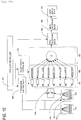
- Fig. 1 is a diagram illustrating a system configuration of a biological information processing apparatus according to a first exemplary embodiment of the present invention.
- the present system includes a probe 001 including a plurality of acoustic conversion elements 002, a system controller 003, a transmission function block 004, an analog-to-digital (A/D) conversion block 005, and a data memory block 006.
- the present system further includes an adding block 007, a post processing block 008, an image processing block 009, an image display device 012, a reception data controller 011, and a light source 013.
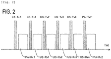
- a timing of performing the photoacoustic tomography and the ultrasonic wave echo will be described with reference to Fig. 2 .
- First light irradiation is performed at a timing represented by PA-Tx1, and a photoacoustic wave emitted from the subject is received and processed during a time period PA-Rxl.
- an ultrasonic wave is transmitted to the subject at timings represented by US-Tx1 to US-Tx4, and received and processed during time periods US-Rx1 to US-Rx4, respectively.
- the next light irradiation is performed at a timing represented by PA-Tx2, and the above-described process is repeated.
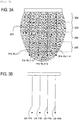
- Fig. 3 illustrates diagrams schematically illustrating a range, inside the subject, acquired by one time light irradiation and the ultrasonic wave echo of multiple times.
- Fig. 3A illustrates that imaging is performed on an area 301 to which light is irradiated at PA-Tx1 of Fig. 2 in a direction indicated by arrows of receiving axes represented by PA-Rx1-1 to PA-Rx1-4.
- the receiving axis refers to a locus of a point on a spatial axis on which image reconstruction is performed at the time of image reconstruction (generation of image data) for generating pixel data or voxel data and represents a locus of an attention point that moves in a depth direction of the subject with respect to the position of the acoustic conversion element in Fig. 3 .
- the area 301 may be divided into areas 302 to 305 that are in an order close to the probe 001.
- Fig. 3B illustrates that the US-TR1 is used as the receiving axis of the ultrasonic wave received, during the time period US-Rx1, corresponding to the ultrasonic wave transmitted at US-Tx1 of Fig.
- the area illustrated in Fig. 3A has the same width as the area illustrated in Fig. 3B .
- Transmission in the ultrasonic wave echo can be converged by transmitting the ultrasonic wave having a shifted timing from the acoustic conversion element.
- the light irradiation area 301 have the width including a plurality of photoacoustic signal receiving axes.
- the acoustic conversion element is an ultrasonic wave transmitter (an acoustic wave transmitter) and also functions as both a first acoustic conversion element (an acoustic conversion element that receives an ultrasonic wave) and a second acoustic conversion element (an acoustic conversion element that receives a photoacoustic wave).
- the first acoustic conversion element and the second acoustic conversion element may be separately prepared, and the present invention is not limited to the above-described example.
- a frequency of the ultrasonic wave transmitted by the ultrasonic wave echo is a first frequency
- a frequency of the photoacoustic wave is a second frequency.
- the A/D conversion block corresponds to an A/D converter of the present invention
- the data memory block corresponds to a data memory.
- the adding block, the post processing block, and the image processing block correspond to a processor that generates image data
- the reception data controller corresponds to a controller.
- a transmission trigger is output from the system controller 003 to the transmission function block 004.
- the transmission function block 004 calculates a delay time to be conferred to transmission for each of the acoustic conversion elements by using the distance from each acoustic conversion element with respect to a focal position in a direction US-TR1 for transmitting the ultrasonic wave and the velocity of sound inside the subject.
- a voltage signal that is an electrical signal shifted by the delay time is transmitted to each acoustic conversion element 002.
- a transmission beam for transmitting the ultrasonic wave or a reception beam of the reflected ultrasonic wave is consistent with the receiving axis.
- the receiving axis represented by US-TR1 of Fig. 3B corresponds to the transmission beam and the reception beam.
- the acoustic conversion element 002 converts the input voltage signal into an ultrasonic wave and transmits the ultrasonic wave to the inside of the subject.
- the ultrasonic wave reflected inside the subject is received by the acoustic conversion element 002, converted into an analog electrical signal (an analog signal), and input to the A/D conversion block 005.
- the input analog electrical signal that is derived from the ultrasonic wave is converted into digital data (a digital signal) and transmitted to the data memory block 006.
- the data memory block 006 retains the input digital data that is derived from the ultrasonic wave in a memory disposed therein.
- the reception data controller 011 outputs a data read location inside the memory to the data memory block 006 based on information related to the receiving axis US-TR1 instructed from the system controller 003.
- the data memory block 006 outputs data, instructed from the reception data controller 011, among retained digital data to the adding block 007 as non-added data.
- FIG. 5 schematically illustrates memories 401 to 405 in the data memory block 006 that correspond to the acoustic conversion elements, respectively.
- 8 CH are present as an input, but for simplification, it is here illustrated that memories corresponding to 5 CH are disposed inside the data memory block 006.
- digital data that is early in reception time is retained in the right of the drawing.
- data, which are instructed to output at the same timing, among non-added data instructed from the reception data controller 011 are expressed by the same color and connected by lines 501.
- the sampling frequency of 40 MHz corresponds to a segment, 25 nanoseconds (1/(2 * F US ), of the memories 401 to 405 in a time direction.
- Data to be output from the data memory block 006 needs to be continuously read from each of the memories 401 to 405 in the time direction without skipping.
- the number of pieces of data per unit time of the non-added data on the receiving axis US-TR1 is the same value as the sampling frequency, that is, 40,000,000.
- the adding block 007 multiplies the weight by each input non-added data according to a need, adds all of the input non-added data, and outputs the added data to the post processing block 008.
- the post processing block computes an envelope curve of the input data and outputs the result to the image processing block 009.
- the image processing block 009 performs various imaging processes such as a rearrangement or smoothing of data appropriate for an observation area or edge emphasis on the input data and transmits the image processing result to the image display device 012 as brightness value data. Finally, an image is displayed on the image display device 012.
- a transmission trigger is output from the system controller 003 to the transmission function block 004.
- the transmission function block generates a signal for driving the light source 013, and so the light source 013 transmits light energy to the subject.
- the light energy is spread to the area 301.
- a photoacoustic wave generated by the light energy is received by the plurality of acoustic conversion elements 002, converted into an analog electrical signal, and then input to the A/D conversion block 005.
- the A/D conversion block 005 converts the input analog electrical signal derived from the photoacoustic wave into digital data and transmits the digital data to the data memory block 006.
- the data memory block 006 retains the input digital data derived from the photoacoustic wave in a memory disposed therein.
- the reception data controller 011 outputs a data read location inside the memory to the data memory block 006 based on information related to the receiving axes PA-Rx1-1, PA-Rx1-2, PA-Rx1-3, and PA-Rx1-4 instructed from the system controller 003.
- the data memory block 006 outputs data, instructed from the reception data controller 011, among retained digital data to the adding block 007 as non-added data.
- FIG. 4 schematically illustrates the memories 401 to 405 in the data memory block 006 that correspond to the individual acoustic conversion elements, respectively. Further, digital data that is early in reception time is retained in the right of the drawing.
- Fig. 4A corresponds to the receiving axis PA-Rx1-1
- Fig. 4B corresponds to the receiving axis PA-Rx1-2
- Fig. 4C corresponds to the receiving axis PA-Rx1-3
- Fig. 4D corresponds to the receiving axis PA-Rx1-4.
- data, which are output at the same timing (time), among non-added data instructed from the reception data controller 011 are expressed by the same color, and data output at the same time are connected by lines as connected by a line 410.
- the sampling frequency of 10 MHz (2 * F PA ) or more becomes necessary.
- the present system performs sampling of 40 MHz (2 * F US ) suitable for the received signal of the ultrasonic wave echo. For this reason, if three of four samples are skipped in the time direction inside the memories 401 to 405 and read as non-added data, processing can be performed without losing information of the signal received by the photoacoustic tomography.
- the number of pieces of data of the non-added data per unit time on each receiving axis becomes smaller than the sampling frequency. That is, the number of pieces of data can become smaller than the number of pieces of data per unit time on each receiving axis in the ultrasonic wave echo.
- the adding block 007 multiplies the weight by each input non-added data, adds all of the input non-added data, and outputs the added data to the post processing block 008.
- the post processing block 008 computes an envelope curve of the input data or performs a calculation expressed by the following Equation 1 and outputs the result to the image processing block 009.
- S in denotes input data
- S out denotes an output
- t denotes a time elapsed since reception of the photoacoustic wave started.
- S out t 2 S in t ⁇ 2 t ⁇ S in t ⁇ t
- the image processing block 009 performs various imaging processes such as a rearrangement or smoothing of data appropriate for an observation area or edge emphasis on the input data and transmits the image processing result to the image display device 012 as brightness value data. Finally, an image is displayed on the image display device 012.
- Fig. 6B illustrates non-added data 605 of the signal received by the ultrasonic wave echo.
- the non-added data present in the right of the drawing is data that is early output from the data memory block 006.
- Eight segments of the non-added data 605 in an up-down direction represent an input of 8 CH to the adding block 007 in Fig. 1 .
- the adding block 007 of the present embodiment is designed to process data of 8 CH as an input for every 40 MHz. That is, the non-added data 605 in the drawing is input "as is" for every 40 MHz. That is, the number of samples per unit time on the receiving axis US-TR1 is 40,000,000.
- Non-added data 601 is non-added data related to the receiving axis PA-Rx1-1.
- non-added data 602 related to the receiving axis PA-Rx1-2 is illustrated.
- non-added data 603 related to the receiving axis PA-Rx1-3 is illustrated.
- non-added data 604 related to the receiving axis PA-Rx1-4 is illustrated in each receiving axis.
- the non-added data related to each receiving axis is data read from the memory in units of four samples, that is, data sampled at 10 MHz.
- the reception process of the ultrasonic wave echo the number of pieces of data per unit time of the non-added data on the receiving axis US-TR1 is 40,000,000. Further, in the reception process of the photoacoustic tomography, the number of pieces of data per unit time of the non-added data on the receiving axes PA-Rx1-1 to PA-Rx1-4 is 10,000,000. Therefore, the reception process of the photoacoustic tomography is smaller in number of data per unit time than the reception process of the ultrasonic wave echo.
- the light energy irradiated to the light irradiation area 301 can be efficiently used for imaging, and the adding ability of the adding block 007 can be efficiently used.
- the SNR of an image does not deteriorate, and the ultrasonic wave echo and the photoacoustic tomography can be processed in real time by a common circuit. Further, the system of the small-sized processing circuit can be obtained.
- the adding block having the input of 8 CH has been described, but the present invention is not limited thereto.
- an input of multiple CH such as 64 CH, 128 CH, and 256 CHmay be implemented.
- the present invention is not limited thereto.
- the receiving axis of the photoacoustic tomography process can increase by N times, and the same effects can be obtained.
- Fig. 7 is a diagram schematically illustrating a system configuration of a biological information processing apparatus according to a second exemplary embodiment of the present invention.
- the system diagram of Fig. 7 is different from the system schematic diagram ( Fig. 1 ) of the first exemplary embodiment of the present system in that the reception data controller 011 is connected even to the A/D conversion block 005. Further, the adding block 007 is a circuit having an adding ability and is expressed by a symbol ⁇ .
- Timing for performing the photoacoustic tomography and the ultrasonic wave echo is the same as in the first exemplary embodiment illustrated in Fig. 2 .
- the significant signal is included up to F US Hz
- the photoacoustic wave obtained by the photoacoustic tomography the significant signal is included up to F PA Hz.
- the present embodiment will be described in connection with a case in which F US is 20 MHz, and F PA is 5 MHz, but the effects of the present invention can be obtained as long as a condition of F US > F PA is satisfied.
- a range inside the subject acquired one time light irradiation and the ultrasonic wave echo of multiple times is the same as illustrated in Fig. 3 .
- the reference numerals 302 to 305 in Fig. 3 represent a range of the depth.
- a system operation at the time of imaging by the ultrasonic wave echo is the same as in the first exemplary embodiment, and a description thereof will not be repeated.
- the sampling frequency of the A/D conversion block 005 is changed by an instruction from the reception data controller 011.
- 10 MHz (2 * F PA ) is described as the changed sampling frequency.
- the changed sampling frequency is lower than the sampling frequency at the time of acquiring the ultrasonic wave echo and higher than the frequency twice as high as the significant signal included in the photoacoustic wave, the effects of the present invention are obtained.
- the generated photoacoustic wave is received by the plurality of acoustic conversion elements 002.
- the plurality of acoustic conversion elements 002 converts the photoacoustic wave into an analog electrical signal and then inputs the analog electrical signal to the A/D conversion block 005.
- the A/D conversion block 005 converts the input analog electrical signal into digital data with the changed sampling frequency of 10 MHz and transmits the digital data to the data memory block 006.
- the data memory block 006 retains the input digital data in a memory disposed therein.
- the reception data controller 011 outputs a data read location inside the memory to the data memory block 006 based on information related to the receiving axes PA-Rx1-1, PA-Rx1-2, PA-Rx1-3, and PA-Rx1-4 instructed from the system controller 003.
- the data memory block 006 outputs data, instructed from the reception data controller 011, among retained digital data to the adding block 007 as non-added data.
- Fig. 9 schematically illustrates the memories 401 to 405 in the data memory block 006 that correspond to the individual acoustic conversion elements, respectively. Further, digital data that is early in reception time is retained in the right of the drawing. In the present embodiment, since sampling is performed at 10 MHz, a signal is retained at every 100 nanoseconds.
- Fig. 9A corresponds to the receiving axis PA-Rx1-1
- Fig. 9B corresponds to the receiving axis PA-Rx1-2
- Fig. 9C corresponds to the receiving axis PA-Rx1-3
- Fig. 9D corresponds to the receiving axis PA-Rx1-4.
- data, which are output at the same timing (time), among non-added data instructed from the reception data controller 011 are expressed by the same color and are connected by lines 910 to 913, lines 920 to 923, lines 930 to 933, and lines 940 to 943.
- the sampling frequency of 10 MHz (2 * F PA ) or more becomes necessary.
- sampling is performed at 10 MHz (2 * F PA ) in the A/D conversion block 005. Therefore, even if it is output as the non-added data "as is" without skipping in the time axis direction, data of a plurality of receiving axes can be processed without losing information.
- Fig. 8 illustrates non-added data of the received signal in the photoacoustic tomography.
- the non-added data present in the right of the drawing is data that is early output from the data memory block 006.
- line numbers 910 to 943 connecting the non-added data that is output at the same time and line represented by dotted lines in Fig. 8 represent the same data. That is, unlike a technique of outputting data of the next receiving axis after outputting all of data of one receiving axis, data is transmitted while sequentially changing the receiving axis.
- data of the receiving axis PA-Rx1-1 is output as the non-added data
- data of the receiving axis PA-Rx1-2 is transmitted.
- data of a reception area of the depth 302 of the receiving axis PA-Rx1-1 is first output.
- data of the reception area of the depth 302 of the receiving axis PA-Rx1-2, data of the reception area of the depth 302 of the receiving axis PA-Rx1-3, and data of the reception area of the depth 302 of the receiving axis PA-Rx1-4 are sequentially output.
- the non-added data is sequentially output starting from data of the reception area of the depth 303 of the receiving axis PA-Rx1-1.
- the non-added data is sequentially output starting from digital data related on an area closest to the acoustic conversion element among the areas inside the subject.
- the reception area refers to a range defined by a predetermined distance range (a predetermined distance range in a direction from the acoustic conversion element to the subject depth) in a certain receiving axis.
- An operation after inputting the output non-added data to the adding block 007 is the same as in the first exemplary embodiment, and a description thereof will not be repeated.
- the number of pieces of data per unit time at the time of the photoacoustic tomography process can be smaller than the number of pieces of data per unit time at the time of the ultrasonic wave echo process.
- data of 8 CH are sequentially input at 40 MHz.
- the noise that causes heat generation of an ADC is reduced, and power consumption of the system is reduced. That is, a biological information processing apparatus that is high in SNR of an image and low in power consumption can be obtained.
- Fig. 10 is a diagram illustrating a system configuration of a biological information processing apparatus according to a third exemplary embodiment of the present invention.
- the present system includes a first probe 017 including a plurality of first acoustic conversion elements 014, a second probe 018 including a plurality of second acoustic conversion elements 015, a system controller 003, a transmission function block 004, and an analog-to-digital (A/D) conversion block 005.
- the present system further includes a data memory block 006, an adding block 007, a post processing block 008, an image processing block 009, an image display device 012, a reception data controller 011, a light source 013, and a switch 016.
- the third exemplary embodiment is the same as in the above-described exemplary embodiments except that two kinds of probes are disposed, and a switch is added.
- the center frequency of the photoacoustic wave in the photoacoustic tomography is different from the center frequency of the reflected ultrasonic wave in the ultrasonic wave echo.
- the acoustic conversion element also has a receivable bandwidth and a center frequency characteristic. For this reason, an optimum acoustic conversion element used in the photoacoustic tomography may be different from an optimum acoustic conversion element used in the ultrasonic wave echo.
- an acoustic conversion element using a PZT may have a center frequency of 1 MHz or 20 MHz, and a fractional bandwidth of about 80% is implemented.
- a CMUT using a semiconductor technology may have a fractional bandwidth exceeding 100%.
- a combination of the acoustic conversion element used in the photoacoustic tomography and the acoustic conversion element used in the ultrasonic wave echo may depend on the observation depth of the target subject or the desired spatial resolution.
- the center frequency of the first acoustic conversion element that receives the reflected ultrasonic wave by the ultrasonic wave echo is preferably higher than the center frequency of the second acoustic conversion element that receives the photoacoustic wave by the photoacoustic tomography.
- the ultrasonic wave can be received at high efficiency.
- the acoustic conversion element 014 of the present embodiment has a center frequency characteristic higher than the acoustic conversion element 015.
- the acoustic conversion element 014 has the center frequency of 12 MHz
- the acoustic conversion element 015 has the center frequency of 3 MHz.
- the switch 016 has a function of switching a connection between the acoustic conversion elements 014 and 015 and the A/D conversion block and can connect any one of the acoustic conversion elements with the A/D conversion block.
- the switch 016 operates to cause a connection with the acoustic conversion element 015, and in the case of performing the ultrasonic wave echo, the switch 017 operates to cause a connection with the acoustic conversion element 014.
- Fig. 11 is a diagram illustrating operation timing. In the case of transmitting light energy at a timing PA-Tx1, a state (SW1) switched to the acoustic conversion element 015 is maintained. Thereafter, during a time period from US-Tx1 to US-Tx4 in which the ultrasonic wave echo is performed, the switch 016 operates to maintain a state (SW2) switched to the acoustic conversion element 14.
- a signal received in each of the photoacoustic wave and the ultrasonic wave echo can be more efficiently converted into an analog electrical signal. Therefore, a biological information processing apparatus that has the higher SNR and an improved image quality can be provided.
Landscapes
- Health & Medical Sciences (AREA)
- Life Sciences & Earth Sciences (AREA)
- Engineering & Computer Science (AREA)
- Physics & Mathematics (AREA)
- Medical Informatics (AREA)
- Animal Behavior & Ethology (AREA)
- Veterinary Medicine (AREA)
- Public Health (AREA)
- Biomedical Technology (AREA)
- Heart & Thoracic Surgery (AREA)
- Biophysics (AREA)
- Molecular Biology (AREA)
- Surgery (AREA)
- Pathology (AREA)
- General Health & Medical Sciences (AREA)
- Nuclear Medicine, Radiotherapy & Molecular Imaging (AREA)
- Radiology & Medical Imaging (AREA)
- Acoustics & Sound (AREA)
- Computer Networks & Wireless Communication (AREA)
- General Physics & Mathematics (AREA)
- Radar, Positioning & Navigation (AREA)
- Remote Sensing (AREA)
- Ultra Sonic Daignosis Equipment (AREA)
Applications Claiming Priority (2)
| Application Number | Priority Date | Filing Date | Title |
|---|---|---|---|
| JP2010031171A JP5725720B2 (ja) | 2010-02-16 | 2010-02-16 | 被検体情報処理装置 |
| EP11706365.1A EP2536338B1 (de) | 2010-02-16 | 2011-02-14 | Vorrichtung zur erfassung von informationen über eine person durch von der person empfangene schallwellen |
Related Parent Applications (2)
| Application Number | Title | Priority Date | Filing Date |
|---|---|---|---|
| EP11706365.1A Division-Into EP2536338B1 (de) | 2010-02-16 | 2011-02-14 | Vorrichtung zur erfassung von informationen über eine person durch von der person empfangene schallwellen |
| EP11706365.1A Division EP2536338B1 (de) | 2010-02-16 | 2011-02-14 | Vorrichtung zur erfassung von informationen über eine person durch von der person empfangene schallwellen |
Publications (1)
| Publication Number | Publication Date |
|---|---|
| EP3199973A1 true EP3199973A1 (de) | 2017-08-02 |
Family
ID=44025234
Family Applications (2)
| Application Number | Title | Priority Date | Filing Date |
|---|---|---|---|
| EP17155970.1A Withdrawn EP3199973A1 (de) | 2010-02-16 | 2011-02-14 | Vorrichtung zur erfassung von informationen über eine person durch von der person empfangene schallwellen |
| EP11706365.1A Not-in-force EP2536338B1 (de) | 2010-02-16 | 2011-02-14 | Vorrichtung zur erfassung von informationen über eine person durch von der person empfangene schallwellen |
Family Applications After (1)
| Application Number | Title | Priority Date | Filing Date |
|---|---|---|---|
| EP11706365.1A Not-in-force EP2536338B1 (de) | 2010-02-16 | 2011-02-14 | Vorrichtung zur erfassung von informationen über eine person durch von der person empfangene schallwellen |
Country Status (5)
| Country | Link |
|---|---|
| US (2) | US20120259198A1 (de) |
| EP (2) | EP3199973A1 (de) |
| JP (1) | JP5725720B2 (de) |
| CN (1) | CN102762153B (de) |
| WO (1) | WO2011102105A1 (de) |
Families Citing this family (18)
| Publication number | Priority date | Publication date | Assignee | Title |
|---|---|---|---|---|
| HUE030134T2 (en) * | 2007-10-16 | 2017-04-28 | Zymogenetics Inc | Combination of transmembrane activator and calcium modulator and cyclophilin ligand interactor (TACI) and anti-CD20 agents for the treatment of autoimmune diseases |
| JP5725720B2 (ja) * | 2010-02-16 | 2015-05-27 | キヤノン株式会社 | 被検体情報処理装置 |
| JP5637725B2 (ja) | 2010-04-12 | 2014-12-10 | キヤノン株式会社 | 音響波イメージング装置 |
| US9289191B2 (en) * | 2011-10-12 | 2016-03-22 | Seno Medical Instruments, Inc. | System and method for acquiring optoacoustic data and producing parametric maps thereof |
| JP5814556B2 (ja) | 2011-02-04 | 2015-11-17 | キヤノン株式会社 | 信号処理装置 |
| JP5796896B2 (ja) * | 2011-03-10 | 2015-10-21 | 富士フイルム株式会社 | 断層画像生成装置及び方法 |
| JP5847490B2 (ja) | 2011-08-25 | 2016-01-20 | キヤノン株式会社 | 被検体情報取得装置 |
| JP5865050B2 (ja) | 2011-12-15 | 2016-02-17 | キヤノン株式会社 | 被検体情報取得装置 |
| US20140182383A1 (en) * | 2012-12-28 | 2014-07-03 | Canon Kabushiki Kaisha | Object information obtaining device, display method, and non-transitory computer-readable storage medium |
| CN103919536B (zh) * | 2013-01-15 | 2018-05-01 | 飞比特公司 | 便携式生物计量监测装置及其操作方法 |
| JP6173159B2 (ja) * | 2013-10-04 | 2017-08-02 | キヤノン株式会社 | 光音響装置 |
| JP2015073577A (ja) * | 2013-10-04 | 2015-04-20 | キヤノン株式会社 | 光音響装置、光音響装置の作動方法、およびプログラム |
| EP2868279A1 (de) * | 2013-10-31 | 2015-05-06 | Canon Kabushiki Kaisha | Vorrichtung zur Erfassung von Personeninformationen |
| JP6351365B2 (ja) * | 2014-05-14 | 2018-07-04 | キヤノン株式会社 | 光音響装置、情報処理方法、プログラム |
| JP6366355B2 (ja) * | 2014-05-14 | 2018-08-01 | キヤノン株式会社 | 光音響装置、信号処理方法、及びプログラム |
| JP6366356B2 (ja) | 2014-05-14 | 2018-08-01 | キヤノン株式会社 | 光音響装置、信号処理方法、及びプログラム |
| JP6166708B2 (ja) * | 2014-10-15 | 2017-07-19 | プレキシオン株式会社 | 光音響波信号変換機および光音響波信号変換機内蔵プローブ |
| JP7195759B2 (ja) | 2018-04-20 | 2022-12-26 | キヤノン株式会社 | 光音響装置および被検体情報取得方法 |
Citations (5)
| Publication number | Priority date | Publication date | Assignee | Title |
|---|---|---|---|---|
| EP1493380A1 (de) * | 2003-07-02 | 2005-01-05 | Kabushiki Kaisha Toshiba | Verfahren und Vorrichtung zur Erzeugung eines Bildes |
| WO2007072490A1 (en) * | 2005-12-23 | 2007-06-28 | Ultraview Ltd. | An operating mode for ultrasound imaging systems |
| WO2007148239A2 (en) * | 2006-06-23 | 2007-12-27 | Koninklijke Philips Electronics, N.V. | Timing controller for combined photoacoustic and ultrasound imager |
| WO2009154298A1 (en) * | 2008-06-18 | 2009-12-23 | Canon Kabushiki Kaisha | Ultrasonic probe, and photoacoustic-ultrasonic system and inspection object imaging apparatus including the ultrasonic probe |
| EP2536338A1 (de) | 2010-02-16 | 2012-12-26 | Canon Kabushiki Kaisha | Vorrichtung zur erfassung von informationen über eine person durch von der person empfangene schallwellen |
Family Cites Families (8)
| Publication number | Priority date | Publication date | Assignee | Title |
|---|---|---|---|---|
| US5685308A (en) * | 1994-08-05 | 1997-11-11 | Acuson Corporation | Method and apparatus for receive beamformer system |
| JP3584328B2 (ja) * | 1995-07-04 | 2004-11-04 | 株式会社日立メディコ | 超音波診断装置 |
| US5891041A (en) * | 1996-11-27 | 1999-04-06 | Hitachi Medical Corporation | Ultrasonic imaging system adapted for use with ultrasonic probes having different center frequencies |
| JPH11216138A (ja) * | 1998-02-05 | 1999-08-10 | Matsushita Electric Ind Co Ltd | 超音波診断装置のビームフォーマ |
| CN1894594B (zh) * | 2003-12-16 | 2010-05-26 | 皇家飞利浦电子股份有限公司 | 具有自动控制穿透度、分辨率和帧速率的超声诊断成像系统 |
| US8137280B2 (en) * | 2005-02-09 | 2012-03-20 | Surf Technology As | Digital ultrasound beam former with flexible channel and frequency range reconfiguration |
| JP5243135B2 (ja) | 2008-07-30 | 2013-07-24 | 帝人デュポンフィルム株式会社 | 太陽電池裏面保護膜用ポリエステルフィルムおよび太陽電池裏面保護膜 |
| JP2008259891A (ja) * | 2008-08-04 | 2008-10-30 | Hitachi Medical Corp | 超音波診断装置 |
-
2010
- 2010-02-16 JP JP2010031171A patent/JP5725720B2/ja active Active
-
2011
- 2011-02-14 CN CN201180009267.1A patent/CN102762153B/zh not_active Expired - Fee Related
- 2011-02-14 WO PCT/JP2011/000791 patent/WO2011102105A1/en not_active Ceased
- 2011-02-14 EP EP17155970.1A patent/EP3199973A1/de not_active Withdrawn
- 2011-02-14 US US13/518,243 patent/US20120259198A1/en not_active Abandoned
- 2011-02-14 EP EP11706365.1A patent/EP2536338B1/de not_active Not-in-force
-
2016
- 2016-07-05 US US15/201,777 patent/US20160331241A1/en not_active Abandoned
Patent Citations (6)
| Publication number | Priority date | Publication date | Assignee | Title |
|---|---|---|---|---|
| EP1493380A1 (de) * | 2003-07-02 | 2005-01-05 | Kabushiki Kaisha Toshiba | Verfahren und Vorrichtung zur Erzeugung eines Bildes |
| JP2005021380A (ja) | 2003-07-02 | 2005-01-27 | Toshiba Corp | 生体情報映像装置 |
| WO2007072490A1 (en) * | 2005-12-23 | 2007-06-28 | Ultraview Ltd. | An operating mode for ultrasound imaging systems |
| WO2007148239A2 (en) * | 2006-06-23 | 2007-12-27 | Koninklijke Philips Electronics, N.V. | Timing controller for combined photoacoustic and ultrasound imager |
| WO2009154298A1 (en) * | 2008-06-18 | 2009-12-23 | Canon Kabushiki Kaisha | Ultrasonic probe, and photoacoustic-ultrasonic system and inspection object imaging apparatus including the ultrasonic probe |
| EP2536338A1 (de) | 2010-02-16 | 2012-12-26 | Canon Kabushiki Kaisha | Vorrichtung zur erfassung von informationen über eine person durch von der person empfangene schallwellen |
Non-Patent Citations (1)
| Title |
|---|
| SRIRANG MANOHAR; SUSANNE E. VAARTJES; JOHAN C. G. VAN HESPEN; JOOST M. KLAASE; FRANK M. VAN DEN ENGH; WIENDELT STEENBERGEN; TON G.: "Initial results of in vivo non-invasive cancer imaging in the human breast using near-infrared photoacoustics", OPT. EXPRESS, vol. 15, 2007, pages 12277 - 12285, XP007918752 |
Also Published As
| Publication number | Publication date |
|---|---|
| WO2011102105A1 (en) | 2011-08-25 |
| CN102762153A (zh) | 2012-10-31 |
| US20160331241A1 (en) | 2016-11-17 |
| US20120259198A1 (en) | 2012-10-11 |
| EP2536338B1 (de) | 2017-04-12 |
| JP5725720B2 (ja) | 2015-05-27 |
| JP2011167228A (ja) | 2011-09-01 |
| CN102762153B (zh) | 2015-05-13 |
| EP2536338A1 (de) | 2012-12-26 |
Similar Documents
| Publication | Publication Date | Title |
|---|---|---|
| EP2536338B1 (de) | Vorrichtung zur erfassung von informationen über eine person durch von der person empfangene schallwellen | |
| JP4528529B2 (ja) | 超音波診断装置及び超音波画像データ処理方法 | |
| US9717477B2 (en) | Ultrasonic diagnosis device and ultrasonic image acquisition method | |
| JPH11221217A (ja) | 超音波診断装置 | |
| CN106618638A (zh) | 一种定量剪切波弹性成像系统 | |
| JP2004181209A (ja) | 超音波診断装置 | |
| Assef et al. | Initial experiments of a 128-channel FPGA and PC-based ultrasound imaging system for teaching and research activities | |
| CN1416782A (zh) | 使用造影剂的超声成像诊断装置 | |
| KR102835058B1 (ko) | 치료 및 이미징 동시 수행방법 및 이를 위한 다기능 초음파 프로브 | |
| CN106618639A (zh) | 一种定量剪切波弹性成像方法 | |
| JP5388416B2 (ja) | 超音波診断装置および超音波診断装置の制御プログラム | |
| US11119199B2 (en) | Acoustic wave image generation apparatus and acoustic wave image generation method | |
| JP2023112108A (ja) | 超音波診断装置 | |
| Assef et al. | A flexible multichannel FPGA and PC-Based ultrasound system for medical imaging research: initial phantom experiments | |
| JP5901739B2 (ja) | 被検体情報処理装置 | |
| KR101861842B1 (ko) | 복수의 주파수를 이용한 고강도 집속 초음파 제어방법과 그를 위한 고강도 집속 초음파 치료 장치 | |
| JP2023531979A (ja) | 連続波ドプラ法のための超音波トランスデューサプローブに基づくアナログ-デジタル変換、並びに関連する装置、システム、及び方法 | |
| JP2010268945A (ja) | 超音波診断装置 | |
| KR101456923B1 (ko) | 애퍼처 컴파운딩을 이용한 초음파 촬영 방법과 그를 위한 초음파 진단 장치 | |
| KR102324390B1 (ko) | 휴대용 하이브리드 초음파 진단장치 | |
| JP2010110642A (ja) | 超音波診断装置 | |
| JP2006192031A (ja) | 超音波画像診断装置 | |
| JP4564544B2 (ja) | 超音波診断装置 | |
| JP2006149603A (ja) | 超音波画像診断装置 | |
| JP2015104395A (ja) | 超音波診断装置 |
Legal Events
| Date | Code | Title | Description |
|---|---|---|---|
| PUAI | Public reference made under article 153(3) epc to a published international application that has entered the european phase |
Free format text: ORIGINAL CODE: 0009012 |
|
| STAA | Information on the status of an ep patent application or granted ep patent |
Free format text: STATUS: THE APPLICATION HAS BEEN PUBLISHED |
|
| AC | Divisional application: reference to earlier application |
Ref document number: 2536338 Country of ref document: EP Kind code of ref document: P |
|
| AK | Designated contracting states |
Kind code of ref document: A1 Designated state(s): AL AT BE BG CH CY CZ DE DK EE ES FI FR GB GR HR HU IE IS IT LI LT LU LV MC MK MT NL NO PL PT RO RS SE SI SK SM TR |
|
| STAA | Information on the status of an ep patent application or granted ep patent |
Free format text: STATUS: REQUEST FOR EXAMINATION WAS MADE |
|
| 17P | Request for examination filed |
Effective date: 20180202 |
|
| RBV | Designated contracting states (corrected) |
Designated state(s): AL AT BE BG CH CY CZ DE DK EE ES FI FR GB GR HR HU IE IS IT LI LT LU LV MC MK MT NL NO PL PT RO RS SE SI SK SM TR |
|
| GRAP | Despatch of communication of intention to grant a patent |
Free format text: ORIGINAL CODE: EPIDOSNIGR1 |
|
| STAA | Information on the status of an ep patent application or granted ep patent |
Free format text: STATUS: GRANT OF PATENT IS INTENDED |
|
| INTG | Intention to grant announced |
Effective date: 20210122 |
|
| STAA | Information on the status of an ep patent application or granted ep patent |
Free format text: STATUS: THE APPLICATION HAS BEEN WITHDRAWN |
|
| 18W | Application withdrawn |
Effective date: 20210519 |