EP3200097A1 - Procédé de traitement de données et collecte de données pour traiter celles-ci - Google Patents
Procédé de traitement de données et collecte de données pour traiter celles-ci Download PDFInfo
- Publication number
- EP3200097A1 EP3200097A1 EP16152991.2A EP16152991A EP3200097A1 EP 3200097 A1 EP3200097 A1 EP 3200097A1 EP 16152991 A EP16152991 A EP 16152991A EP 3200097 A1 EP3200097 A1 EP 3200097A1
- Authority
- EP
- European Patent Office
- Prior art keywords
- data
- cumulative
- accrual
- predetermined
- period
- Prior art date
- Legal status (The legal status is an assumption and is not a legal conclusion. Google has not performed a legal analysis and makes no representation as to the accuracy of the status listed.)
- Withdrawn
Links
Images


Classifications
-
- H—ELECTRICITY
- H04—ELECTRIC COMMUNICATION TECHNIQUE
- H04N—PICTORIAL COMMUNICATION, e.g. TELEVISION
- H04N1/00—Scanning, transmission or reproduction of documents or the like, e.g. facsimile transmission; Details thereof
- H04N1/32—Circuits or arrangements for control or supervision between transmitter and receiver or between image input and image output device, e.g. between a still-image camera and its memory or between a still-image camera and a printer device
- H04N1/32101—Display, printing, storage or transmission of additional information, e.g. ID code, date and time or title
- H04N1/32106—Display, printing, storage or transmission of additional information, e.g. ID code, date and time or title separate from the image data, e.g. in a different computer file
- H04N1/32122—Display, printing, storage or transmission of additional information, e.g. ID code, date and time or title separate from the image data, e.g. in a different computer file in a separate device, e.g. in a memory or on a display separate from image data
-
- G—PHYSICS
- G06—COMPUTING OR CALCULATING; COUNTING
- G06F—ELECTRIC DIGITAL DATA PROCESSING
- G06F11/00—Error detection; Error correction; Monitoring
- G06F11/30—Monitoring
- G06F11/3055—Monitoring arrangements for monitoring the status of the computing system or of the computing system component, e.g. monitoring if the computing system is on, off, available, not available
-
- G—PHYSICS
- G06—COMPUTING OR CALCULATING; COUNTING
- G06F—ELECTRIC DIGITAL DATA PROCESSING
- G06F11/00—Error detection; Error correction; Monitoring
- G06F11/30—Monitoring
- G06F11/34—Recording or statistical evaluation of computer activity, e.g. of down time, of input/output operation ; Recording or statistical evaluation of user activity, e.g. usability assessment
- G06F11/3466—Performance evaluation by tracing or monitoring
- G06F11/3495—Performance evaluation by tracing or monitoring for systems
-
- G—PHYSICS
- G06—COMPUTING OR CALCULATING; COUNTING
- G06F—ELECTRIC DIGITAL DATA PROCESSING
- G06F16/00—Information retrieval; Database structures therefor; File system structures therefor
- G06F16/20—Information retrieval; Database structures therefor; File system structures therefor of structured data, e.g. relational data
- G06F16/25—Integrating or interfacing systems involving database management systems
-
- G—PHYSICS
- G06—COMPUTING OR CALCULATING; COUNTING
- G06F—ELECTRIC DIGITAL DATA PROCESSING
- G06F16/00—Information retrieval; Database structures therefor; File system structures therefor
- G06F16/50—Information retrieval; Database structures therefor; File system structures therefor of still image data
- G06F16/51—Indexing; Data structures therefor; Storage structures
-
- G—PHYSICS
- G06—COMPUTING OR CALCULATING; COUNTING
- G06F—ELECTRIC DIGITAL DATA PROCESSING
- G06F3/00—Input arrangements for transferring data to be processed into a form capable of being handled by the computer; Output arrangements for transferring data from processing unit to output unit, e.g. interface arrangements
- G06F3/12—Digital output to print unit, e.g. line printer, chain printer
- G06F3/1201—Dedicated interfaces to print systems
- G06F3/1202—Dedicated interfaces to print systems specifically adapted to achieve a particular effect
- G06F3/1203—Improving or facilitating administration, e.g. print management
- G06F3/1207—Improving or facilitating administration, e.g. print management resulting in the user being informed about print result after a job submission
-
- G—PHYSICS
- G06—COMPUTING OR CALCULATING; COUNTING
- G06F—ELECTRIC DIGITAL DATA PROCESSING
- G06F3/00—Input arrangements for transferring data to be processed into a form capable of being handled by the computer; Output arrangements for transferring data from processing unit to output unit, e.g. interface arrangements
- G06F3/12—Digital output to print unit, e.g. line printer, chain printer
- G06F3/1201—Dedicated interfaces to print systems
- G06F3/1223—Dedicated interfaces to print systems specifically adapted to use a particular technique
- G06F3/1237—Print job management
- G06F3/1273—Print job history, e.g. logging, accounting, tracking
-
- G—PHYSICS
- G06—COMPUTING OR CALCULATING; COUNTING
- G06F—ELECTRIC DIGITAL DATA PROCESSING
- G06F3/00—Input arrangements for transferring data to be processed into a form capable of being handled by the computer; Output arrangements for transferring data from processing unit to output unit, e.g. interface arrangements
- G06F3/12—Digital output to print unit, e.g. line printer, chain printer
- G06F3/1201—Dedicated interfaces to print systems
- G06F3/1278—Dedicated interfaces to print systems specifically adapted to adopt a particular infrastructure
- G06F3/1285—Remote printer device, e.g. being remote from client or server
-
- G—PHYSICS
- G06—COMPUTING OR CALCULATING; COUNTING
- G06F—ELECTRIC DIGITAL DATA PROCESSING
- G06F3/00—Input arrangements for transferring data to be processed into a form capable of being handled by the computer; Output arrangements for transferring data from processing unit to output unit, e.g. interface arrangements
- G06F3/12—Digital output to print unit, e.g. line printer, chain printer
- G06F3/1293—Printer information exchange with computer
- G06F3/1294—Status or feedback related to information exchange
-
- H—ELECTRICITY
- H04—ELECTRIC COMMUNICATION TECHNIQUE
- H04N—PICTORIAL COMMUNICATION, e.g. TELEVISION
- H04N1/00—Scanning, transmission or reproduction of documents or the like, e.g. facsimile transmission; Details thereof
- H04N1/00127—Connection or combination of a still picture apparatus with another apparatus, e.g. for storage, processing or transmission of still picture signals or of information associated with a still picture
- H04N1/00323—Connection or combination of a still picture apparatus with another apparatus, e.g. for storage, processing or transmission of still picture signals or of information associated with a still picture with a measuring, monitoring or signaling apparatus, e.g. for transmitting measured information to a central location
-
- G—PHYSICS
- G06—COMPUTING OR CALCULATING; COUNTING
- G06F—ELECTRIC DIGITAL DATA PROCESSING
- G06F2201/00—Indexing scheme relating to error detection, to error correction, and to monitoring
- G06F2201/835—Timestamp
-
- G—PHYSICS
- G06—COMPUTING OR CALCULATING; COUNTING
- G06F—ELECTRIC DIGITAL DATA PROCESSING
- G06F2201/00—Indexing scheme relating to error detection, to error correction, and to monitoring
- G06F2201/88—Monitoring involving counting
-
- H—ELECTRICITY
- H04—ELECTRIC COMMUNICATION TECHNIQUE
- H04N—PICTORIAL COMMUNICATION, e.g. TELEVISION
- H04N2201/00—Indexing scheme relating to scanning, transmission or reproduction of documents or the like, and to details thereof
- H04N2201/0077—Types of the still picture apparatus
- H04N2201/0094—Multifunctional device, i.e. a device capable of all of reading, reproducing, copying, facsimile transception, file transception
-
- H—ELECTRICITY
- H04—ELECTRIC COMMUNICATION TECHNIQUE
- H04N—PICTORIAL COMMUNICATION, e.g. TELEVISION
- H04N2201/00—Indexing scheme relating to scanning, transmission or reproduction of documents or the like, and to details thereof
- H04N2201/32—Circuits or arrangements for control or supervision between transmitter and receiver or between image input and image output device, e.g. between a still-image camera and its memory or between a still-image camera and a printer device
- H04N2201/3201—Display, printing, storage or transmission of additional information, e.g. ID code, date and time or title
- H04N2201/3202—Display, printing, storage or transmission of additional information, e.g. ID code, date and time or title of communication or activity log or report
-
- Y—GENERAL TAGGING OF NEW TECHNOLOGICAL DEVELOPMENTS; GENERAL TAGGING OF CROSS-SECTIONAL TECHNOLOGIES SPANNING OVER SEVERAL SECTIONS OF THE IPC; TECHNICAL SUBJECTS COVERED BY FORMER USPC CROSS-REFERENCE ART COLLECTIONS [XRACs] AND DIGESTS
- Y02—TECHNOLOGIES OR APPLICATIONS FOR MITIGATION OR ADAPTATION AGAINST CLIMATE CHANGE
- Y02D—CLIMATE CHANGE MITIGATION TECHNOLOGIES IN INFORMATION AND COMMUNICATION TECHNOLOGIES [ICT], I.E. INFORMATION AND COMMUNICATION TECHNOLOGIES AIMING AT THE REDUCTION OF THEIR OWN ENERGY USE
- Y02D10/00—Energy efficient computing, e.g. low power processors, power management or thermal management
Definitions
- the present invention relates to a method for processing data and to a data collector for processing data. More particularly, the data may be data of a parameter counter for an image forming process.
- Data collection methods are used in information processing practice.
- the data may relate to the processes of an image forming apparatus, for example.
- Data relating to an image forming apparatus are collected by a data collector.
- the data are stored in a data collector database in the data collector.
- a data collector database may store of the order of about 100 gigabytes of data, for example.
- the data collector may receive data for these counters by polling the image forming apparatuses.
- the polling can be unreliable in that sometimes an image forming apparatus may not respond to provide the data.
- An aim of the present invention is to provide a method for processing data of a parameter counter for an image forming process, in which data can be collected and stored more cheaply, efficiently and/or more quickly compared to the prior art.
- a further aim of the present invention is to provide a data collector that can carry out a method of the present invention.
- an aim of the present invention is to provide a data collector that can collect and store data more cheaply, more efficiently and/or more quickly compared to the prior art.
- a method for processing data of a parameter counter for an image forming process comprises: providing a cumulative data structure for storing at least one record for recording for a predetermined accrual period a cumulative total for a parameter counter for an image forming process; providing data of a parameter counter for a time period; determining whether or not the time period corresponds to a predetermined accrual period for which an existing cumulative total is recorded in the cumulative data structure; and updating the cumulative data structure based on the data of the parameter counter. If it is determined that the time period corresponds to a predetermined accrual period for which an existing cumulative total is recorded in the cumulative data structure, the updating comprises updating the existing cumulative total. If it is determined that the time period does not correspond to a predetermined accrual period for which an existing cumulative total is recorded in the cumulative data structure, the updating comprises starting a new cumulative total for a new predetermined accrual period to which the time period corresponds.
- the method for processing data consolidates the data. This permits automatic binding of already recorded data into specific records of a coarser granularity, based on the required aggregation time granule (accrual period).
- the reporting speed depends on the amount of data required to be extracted, evaluated and processed. Accordingly, the present invention reduces the amount of data stored in the data collecting database, thereby speeding up reporting.
- the present invention provides an efficient method for parameter counters to be stored and reported on.
- the method comprises producing the data of the parameter counter for the time period by calculating the difference between two parameter counter values at different times.
- the present invention can robustly consolidate data inline (i.e. as it is stored rather than after it has been stored) even when polling of the image forming apparatuses is unreliable.
- the data of the parameter counter for the time period does not add to the amount of data stored in the data collector database. This helps to reduce the time it takes for data for a report to be outputted from the data collector database.
- the cumulative data structure is stored in a data collector database from which data of the parameter counter is outputted for a report.
- the data collector database can be updated inline.
- the data collector database can be updated. This means that it is not necessary for the records that form the data collector database to be generated elsewhere and subsequently moved to the data collector database. This helps to reduce the amount of memory required and to reduce the number of processing steps.
- the cumulative data structure is stored in a cache memory that is separate from a data collector database from which data of the parameter counter is outputted for a report.
- the data collector database can be used for storing only records for completed accrual periods. Until an accrual period is finished the record can be stored in a separate cache memory. This helps to improve the quality of the data stored in the data collector database.
- the record recording the predetermined accrual period and the existing cumulative total is stored in the data collector database.
- the data is permanently stored only after it has been consolidated. This reduces the data sparsity (i.e. increases the data density) in the data collector database, which speeds up reporting from the data collector database.
- the record is deleted from the cache memory.
- the record is wiped from the cache memory (or other memory in which the cumulative data structure is stored). This reduces the size of the cache memory required.
- the record is copied from the cache memory to the data collector database without undergoing substantially any data format transformation before being stored in the data collector database.
- the method comprises outputting from the data collector database data of the parameter counter for a report based on the information stored in the data collector database.
- a report can be produced more quickly and efficiently from the data collector database that has higher data density.
- each record stores for each predetermined accrual period one or more of: a unique identifier for an image forming apparatus that performed the image forming process that the parameter counter is for; a start accrual interval timestamp indicating a start of a predetermined accrual period; an end accrual interval timestamp indicating an end of a predetermined accrual period; a personal identifier indicating a user that instructed the image forming process that the parameter counter is for; and a parameter identifier indicating the image forming process.
- data can be stored in a manner that distinguishes between different image forming apparatuses, different image forming processes, different accrual periods, and different users.
- the data of the parameter counter is deleted from the cache memory in which the cumulative data structure is stored.
- the method comprises identifying that the parameter counter of which the data is provided for the time period corresponds to the parameter counter for which an existing cumulative total is recorded in the cumulative data structure.
- the cumulative data structure stores a record for each of a plurality of parameter counters.
- the new predetermined accrual period is chronologically subsequent to the predetermined accrual period for which the existing cumulative total is recorded in the cumulative data structure.
- the parameter counter is of a cumulative type.
- cumulative-type data can be efficiently stored based on predetermined accrual periods corresponding to different periods in time.
- the data collector database stores the records according to a relational database management system.
- the cumulative data structure stores the records according to a relational database management system.
- a standard relational database system can be used to store the data in the data collector database.
- the relational database management system is for data storage.
- the relational database management system is cheap, easily manageable, efficient in data storage and widespread on the market. Hence, data can be stored efficiently in the data collector database.
- a data collector for processing data of a parameter counter for an image forming process.
- the data collector comprises: a cumulative data structure for storing at least one record for recording for a predetermined accrual period a cumulative total for a parameter counter for an image forming process; an determining unit configured to, for data of a parameter counter for a time period, determine whether or not the time period corresponds to a predetermined accrual period for which an existing cumulative total is recorded in the cumulative data structure; and an updating unit configured to update the cumulative data structure based on the data of the parameter counter. If the determining unit determines that the time period corresponds to a predetermined accrual period for which an existing cumulative total is recorded in the cumulative data structure, the updating unit is configured to update the existing cumulative total.
- the updating unit is configured to start a new cumulative total for a new predetermined accrual period to which the time period corresponds.
- FIG. 1 schematically depicts a system for data collection and data storage according to an embodiment of the invention.
- a data collector 10 is connected to one or more image forming apparatuses 20.
- the image forming apparatus 20 is configured to output data of a parameter counter for an image forming process.
- the data collector 10 is configured to store a data collector database.
- the data collector database is stored in data storage 13.
- the data collector 10 obtains data from one or more image forming apparatuses 20.
- data is written into the data collector database in the data storage 13 via a data processor 12.
- the data collector 10 may be in data communication with of the order of about 100 or 1000 image forming apparatuses 20.
- the data form the image forming apparatuses 20 may be stored in the data collector database in the data storage 13 for several years.
- each data collector 10 may store a large amount of data in the corresponding data collector database.
- a data collector database may store of the order of about 100 gigabytes of data, for example.
- the data collector 10 is in data communication with a plurality of image forming apparatuses 20 in a local system or in a distributed system of devices. This system of devices has to be controlled and maintained.
- the image forming apparatuses 20 can be printers, copiers, facsimile devices, multifunction peripherals (MFPs) or a mixture of these devices, for example.
- the image forming apparatuses 20 may be accessed through other entities such as, for example, personal computers or servers.
- the image forming apparatuses 20 may be accessed directly.
- the data is data relating to the image forming apparatuses 20.
- the network a large amount of data specific to each image forming apparatus 20 is stored.
- different types of image forming apparatus e.g. image forming apparatuses made by different manufacturers, are provided in the network.
- the image forming apparatuses 20 in the network provide data in different formats, which are collected by the data collector 10.
- the image forming apparatuses 20 included in the network may vary with respect to their type, manufacturer, capabilities, etc.
- the data collector database is flexible so as to support data in different formats from different types of image forming apparatuses 20.
- the data collector outputs data for a report via a reporting application.
- the reporting application may send a request to the data collector 10 for acquiring the data for the report.
- the data collector 10 outputs the data for the report from the data collector database in the data storage 13.
- the data collector 10 comprises a cache memory 121.
- This is depicted in Figure 1 and also in Figure 2 , which schematically depicts the data processor 12 of the data collector 10.
- the cache memory 121 may be part of the data processor 12 of the data collector 10.
- the cache memory 121 may be separate from the data processor 12, with the data processor 12 in communication with the cache memory 121.
- the data processor 12 is configured to write and modify data stored in the cache memory 121.
- the data collector 10 is configured to store and update a cumulative data structure.
- the cumulative data structure stores at least one record 30.
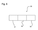
- Figure 5 schematically depicts an example of a record 30 of the cumulative data structure for use in an embodiment of the present invention.
- the cumulative data structure is stored in the data collector database in the data storage 13.
- the cumulative data structure may form the data collector database.
- the data processor 12 updates individual records 30 of the data collector database.
- the cumulative data structure may be stored in the cache memory 121.
- the data processor 12 updates individual records 30 stored in the cache memory 121. Completed records 30 from the cumulative data structure may subsequently be stored in the data collector database in the data storage 13.
- Each record 30 is for recording a cumulative total 32 for a parameter counter for an image forming process.
- the parameter counter may be a front page counter (e.g. the number of times that the front of a page has been printed).
- Alternative parameter counters may correspond to the number of scans performed, the number of faxes, the number of times that the back of a page has been printed or the number of duplex pages printed (i.e. the number of times that both the front and the back of a page have been printed).
- the cumulative total 32 corresponds to the total count for that parameter counter within a predetermined accrual period.
- the cumulative total 32 is an approximation of the total for the predetermined accrual period.
- the cumulative total 32 may not correspond to the exact count for the predetermined accrual period. This is because the beginning and end of the time periods may not necessarily correspond to the beginning and end of the predetermined accrual period.
- the predetermined accrual period corresponds to a reporting time interval.
- the predetermined accrual period may correspond to a period of one month or a period of a quarter, for example.
- the predetermined accrual period is not particularly limited and may alternatively be one day, one week or one year, for example.
- the cumulative total 32 is recorded for the predetermined accrual period.
- the cumulative total 32 is associated with the predetermined accrual period in the record 30.
- the record 30 may record a start accrual interval timestamp 31 and an end accrual interval timestamp 33 for the predetermined accrual period.
- the predetermined accrual period has a particular length (e.g. one month or one quarter, or even one week), and also corresponds to a particular period in time.
- the record 30 records the cumulative total 32 for the predetermined accrual period that is defined by the start accrual interval timestamp 31 and the end accrual interval timestamp 33.
- the start accrual interval timestamp 31 indicates the start of the predetermined accrual period.
- the end accrual interval timestamp 33 indicates the end of the predetermined accrual period.
- Each of the start accrual interval timestamp 31 and the end accrual interval timestamp 33 may be a sequence of characters or coded information identifying when the start and end, respectively, of the predetermined accrual period occurred.
- the start accrual interval timestamp 31 and the end accrual interval timestamp 33 may give the date and time of day.
- the method for processing data comprises providing data of a parameter counter for a time period.
- the time period is different from the predetermined accrual period.
- Data may be collected by the data collector 10 at regular intervals.
- the data collector 10, or a data collector application may poll (e.g. send a request to) a plurality of image forming apparatuses 20 to request data of parameter counters for the relevant image forming apparatus 20. Accordingly, data coming from the image forming apparatuses 20 is collected regularly in time.
- the parameter counter is of a cumulative type.
- the counter value provided by the image forming apparatus 20 indicates the value of the specific parameter at a specific moment in time.
- the counter value may have increased or may have stayed the same (but does not decrease).
- a parameter counter of the cumulative type may be total printed pages.
- Other examples of parameter counters of the cumulative type include a copy counter, a scan counter, a fax counter, etc.
- the time period (for which data of the parameter counter is provided to the data collector 10) is the time period between two moments in time for which the counter value of the parameter counter is known.
- the time period may be the time period between two moments in time at which the image forming apparatus 20 was polled.
- FIG. 4 depicts a schematic diagram illustrating data sparsity for an image forming apparatus 20.
- each bar represents a different parameter counter.
- each section represents a counter value at a different timing 1 to 14.
- the top bar corresponds to a front page counter.
- the second bar corresponds to a back page counter.
- the third bar corresponds to a scan counter.
- the fourth (i.e. bottom) bar corresponds to a fax counter.
- the top bar of Figure 4 shows that counter value data for the front page counter existed for timings 1 to 7 and 12 to 14 but did not exist for timings 8 to 11.
- data of a parameter counter for a plurality of time periods is provided.
- data of the front page counter for the time period between timing 1 and timing 2 may be provided. This corresponds to the number of front pages printed after timing 1 and before timing 2.
- data of the front page counter for a time period between timings 2 and 3 may be provided. This corresponds to the number of front pages printed after timing 2 and before timing 3.
- Data for other time periods can be similarly provided.
- data of the front page counter for the time period between timings 7 and 12 can be provided. This corresponds to the number of front pages printed after timing 7 and before timing 12.
- Data for the other types of parameter counters can be provided in the same way.
- the data collector 10 comprises a data acquisitor 11.
- the data acquisitor 11 is configured to receive counter values at different timings from the image forming apparatus 20.
- the data acquisitor 11 is configured to produce the data of the parameter counter for the time period by calculating the difference between two parameter counter values polled at different times. For example, the data acquisitor 11 may subtract the counter value at timing 1 from the counter value at timing 2 in order to produce the data of the parameter counter for the time period between timing 1 and timing 2.
- the image forming apparatus 20 may output the data of the parameter counter for the time period, such that it is not necessary for the data acquisitor 11 to produce this data of the parameter counter for the time period.
- the time periods are set by the timings at which the image forming apparatus 20 is polled, or by the time periods used by the particular image forming apparatuses 20 for counting the parameter.
- the time periods do not necessarily correspond to the predetermined accrual periods of interest for reporting purposes.
- the time periods can be inconsistent due to the image forming apparatus 20 being unavailable or offline.
- the time period between timing 1 and timing 2 is shorter than the time period between timing 7 and timing 12.
- the time period for one image forming apparatus may be different from the time period for a different image forming apparatus.
- the record 30 records a cumulative total for a predetermined accrual period defined by the start accrual interval timestamp 31 and the end accrual interval timestamp 33.
- the method for processing data comprises determining whether or not the time period corresponds to the predetermined accrual period for which an existing cumulative total 32 is recorded in the record 30. It is determined whether the data of the parameter counter for the time period should be added to the existing cumulative total 32 or whether it belongs to a different accrual period.
- the data of the parameter counter for the time period (i.e. the counter value for that time period) is provided in association with a polling timestamp.
- a polling timestamp indicates a time which the image forming apparatus 20 was polled.
- the polling timestamp may correspond to timing 2 indicating the end of the time period.
- the polling timestamp may correspond to timing 1, indicating the start of the time period.
- the data of the parameter counter for the time period comprises polling timestamps indicating both the start and end of the time period.
- the determination of whether or not the time period corresponds to the predetermined accrual period of the record 30 in the cumulative data structure comprises comparing the polling timestamp to the start accrual interval timestamp 31 and/or the end accrual interval timestamp 33 in the record 30. For example, if the polling timestamp is after the start accrual interval timestamp 31 and before the end accrual interval timestamp 33, then it is determined that the time period corresponds to the predetermined accrual period for which the existing cumulative total 32 is recorded in the record 30.
- the polling timestamp used for this comparison may correspond to the polling timestamp that indicates the end of the time period, or alternatively may be the polling timestamp that indicates the start of the time period.
- a midpoint between the start and end of the time period may be used as the comparator for comparing to the start accrual interval timestamp 31 and the end accrual interval timestamp 33 in the record 30.
- the record 30 is then updated based on the data of the parameter counter.
- the cumulative data structure stores a record 30 for each of a plurality of parameter counters.
- a parameter counter may be specific to a particular type of image forming process (e.g. printing front page, printing back page, scanning a page, faxing a page, etc.). Additionally or alternatively a parameter counter may be specific to a specific user of image forming apparatuses 20. Accordingly, it can be recorded how many of a particular type of image forming process is performed by a particular user on a particular image forming apparatus 20. However, it is not necessary for the parameter counter to be specific to a specific user.
- a parameter counter can be specific to a specific image forming apparatus 20. Accordingly it can be recorded how many of a particular type of image forming process is performed by anyone on a particular image forming apparatus 20. It is not necessary for the parameter counter to be specific to a particular image forming apparatus 20. For example, it can be recorded how many of a particular image forming process is performed on any image forming apparatuses by a particular user. Alternatively, it can be recorded how many of a particular image forming process is performed by any user on any image forming apparatus.
- the updating comprises starting a new cumulative total for a new predetermined accrual period to which the time period corresponds.
- a new record 30 may be created to record the new cumulative total for the new predetermined accrual period. For example, if the record 30 is for the accrual period of January and the data of the parameter counter is for a time period in February, then a new cumulative total for a new predetermined accrual period of February is started in a new record 30. The new record 30 is stored in the cumulative data structure.
- the method for processing data consolidates the data. This permits automatic binding of already recorded data into specific, additional records of a coarser granularity, based on the required aggregation time granule (accrual period).
- the initial data for an image forming apparatus could include hours and minutes based on polling counter data.
- the data collector 10 may require only monthly based granularity for monthly accruals. Therefore, the present invention provides a mechanism which allows hours and minutes based polling counting data to be linked to finitely defined monthly accounting intervals. This makes it possible to report counter values for image forming apparatuses over the accounting periods of months. The reporting speed depends on the amount of data required to be extracted, evaluated and processed. Accordingly, the present invention reduces the amount of data stored in the data collecting database, thereby speeding up reporting.
- the present invention provides an efficient method for parameter counters to be stored and reported on.
- data is processed inline, such that only processed data (i.e. consolidated data) is stored in the data collector database in the data storage 13 of the data collector 10.
- the present invention can reduce the burden on reporting by storing only data that is useful for reporting.
- Figure 3 schematically depicts a flow chart illustrating a method for processing data according to an embodiment of the invention.
- the method starts at A.
- the accrual period boundaries are calculated. For example, the start and end boundaries of an accrual period of one week are calculated.
- the cumulative data structure which may be stored in the data collector database in the data storage 13 or in the cache memory 121, may store a plurality of records 30 corresponding to different parameter counters. There may be a plurality of records 30 for different parameter counters over the same predetermined accrual period.
- the method comprises identifying that the parameter counter of which the data is provided for the time period corresponds to the parameter counter for which the cumulative total 32 is recorded in the record 30.
- the parameter counter may be identified by a unique identifier of an image forming apparatus 20, a personal identifier of a user and/or an identifier of the image forming process.
- the identified parameter counter can be compared to the parameter counters for which records 30 are stored in the cumulative data structure. When a match is found, the time period can be compared to the predetermined accrual period for that record 30 so as to determine if the data for that time period belongs to the predetermined accrual period or to a different (e.g. later) accrual period.
- Step S11 it is determined whether or not the time period corresponds to the predetermined accrual period for which the existing cumulative total is recorded in a record 30 stored in the cumulative data structure. For example, the time period (for which data of the parameter counter is provided) is compared to the boundaries of the predetermined accrual period for which the existing cumulative total 32 is recorded in a record 30 stored in the cumulative data structure. If it is determined that the time period does not correspond to the predetermined accrual period for which the existing cumulative total 32 is recorded, then it may be determined that the time period corresponds to a new predetermined accrual period.
- Step S 13 it is determined whether an accrual begin interval exists in a record 30 stored in the cumulative data structure. This may be done by determining whether a start accrual interval timestamp 31 exists for a record 30 for the parameter counter. If the start accrual interval timestamp 31 exists, then this means that the current (i.e. open) record 30 for that parameter counter corresponds to the old predetermined accrual period (i.e. an accrual period that has finished). Accordingly, in Step S 14, that record 30 is closed. This means that the information in the record 30 is stored (e.g. for longer term storage) in the data storage 13, for example in a data collector database. When it is determined that the time period does not correspond to the predetermined accrual period for which the existing cumulative total 32 is recorded in a record 30 stored in the cumulative data structure, the information of the predetermined accrual period and the existing cumulative total 32 is stored in the data collector database.
- Step S15 s new record 30 is created.
- a new record 30 is created and a start accrual interval timestamp 31 may be inserted in the new record 30.
- the data of the parameter counter for the time period is used to start the new cumulative total 32 for the new record 30.
- Step S 13 if it is determined that no accrual begin interval exists in the current record, then this means that there is no information to be stored for longer term storage in the data collector database and the method can proceed straight to Step S 15 where a new record 30 is started. The method then ends at B.
- Step S11 if in Step S11 it is determined that the time period corresponds to a predetermined accrual period for which an existing cumulative total is recorded for that parameter counter, then processing proceeds to Step S12. In Step S12 the existing cumulative total 32 is updated based on the counter value for the parameter counter for the time period. The method then ends at Step B.
- the method of the present invention includes two stages of data processing.
- the recorded fine granular data is registered inside the caching subsystem of the data collector 10.
- the data is registered based on the time interval of interest of data processing.
- counter data is finally stored inside the data collector database in the data storage 13 of the data collector 10.
- data for a cumulative parameter can be processed and consolidated inline. This means that instead of storing a large amount of data that is subsequently consolidated, the data is consolidated as it is stored. This reduces the amount of storage space required to store the information that is useful for reporting. This is possible even for cumulative parameters where the cumulative total is provided in response to polling.
- the information that is useful for reporting can be stored in the data collector database from which it can be accessed for reports.
- the data collector database has high density (low sparsity) data in that a high proportion of the data stored in the data collector database is useful for reporting.
- each record 30 may be stored temporarily in the cache memory 121 while it is being updated (i.e. until the accrual period is finished). In this case, after the record 30 is stored in the data collector database, that record 30 may be deleted from the cumulative data structure. Accordingly, after each record 30 is written into the data collector database, the record 30 is wiped from the cache memory 121 (or other memory in which the cumulative data structure is stored). This reduces the size of the cache memory 121 required.
- the record 30 is copied from the cache memory 121 to the data collector database without undergoing substantially any data format transformation before being stored in the data collector database. Accordingly, an embodiment of the present invention provides a simple and efficient way of storing useful data. No data format transformation is required, thereby reducing the required processing power to store the information in a manner that can be accessed efficiently for reporting.
- the updating of the cumulative data structure comprises creating a new record 30 for a new predetermined accrual period or a new parameter counter, for example.
- the data of the parameter counter for the time period corresponds to an existing record 30, then that existing record 30 may be updated.
- the data of the parameter counter is no longer needed, such that it does not need to be stored. This reduces the size of the cache memory 121 required for the method for processing data.
- data for a plurality of parameter counters can be stored, and consolidated as it is stored, simultaneously, using the same memory. This provides an efficient way to record the information that is required for reporting.
- the data collector database and/or the cumulative data structure stores the at least one record 30 according to a relational database management system.
- a standard relational database system can be used to store the data in the data collector database.
- the relational database management system is for data storage.
- the relational database management system is cheap, easily manageable, efficient in data storage and widespread on the market. Hence, data can be stored efficiently in the data collector database.
- FIG. 2 schematically depicts the data processor 12 of a data collector 10 according to an embodiment of the invention.
- the data processor 12 comprises the cache memory 121.
- the data processor 12 comprises a determining unit 122.
- the determining unit is configured to determine whether or not the time period corresponds to a predetermined accrual period for which an existing cumulative total is recorded in the cumulative data structure.
- the determining unit 122 is connected to the cache memory 121. This allows the determining unit 122 to access the information stored in the cache memory 121.
- the data processor 12 comprises an updating unit 123.
- the updating unit 123 is configured to calculate the data of the parameter counter.
- the updating unit 123 is configured to update the cumulative data structure based on the data of the parameter counter.
- the updating unit 123 is connected to the cache memory 121. This allows the updating unit 123 to write data into the cumulative data structure stored in cache memory 121.
- the data acquisitor 11 may poll an image forming apparatus 20 and calculate a counter value for a time period. The data acquisitor 11 then sends the counter value (i.e. data of the parameter counter for the time period) to the data processor 12.
- the data processor 12 calculates the data of the parameter counter for the time period.
- the data processor 12 updates a record 30 based on the data of the parameter counter.
- the updating unit 123 is configured to update the records 30 in the cumulative data structure.
- the updating unit 123 is connected to the data storage 13. This allows the updating unit 123 to write data into the cumulative data structure if it is stored in data storage 13.
- the updating unit 123 can store records 30 in the data collector database in the data storage 13.
- the cumulative total 32 stored in the record 30 may be only an approximation of the true counter value (e.g. the true number of front pages printed) within the predetermined accrual period. This is because the beginning and end of the time periods may not necessarily correspond to the beginning and end of the predetermined accrual period. Taking the example of Figure 4 , if the boundary between two predetermined accrual periods were to fall between timing 7 and timing 12, then it could not be known how many of the front pages are printed between timing 7 and timing 12 were printed in one predetermined accrual period as opposed to the other. The present invention provides a robust way of storing the data by providing this approximation.
- the true counter value e.g. the true number of front pages printed
- the image forming process examples include a printing process, a copying process and a faxing process.
- the image forming process can be formed on an image forming apparatus.
- Examples of the image forming apparatus include a printer, a copier and a facsimile device.
- other devices such as refrigerators, washing machines, TV's and mobile phones can be accessed through other devices such as a personal computer or a server, for example. These devices can also be accessed directly. These devices can provide or contain data which may be in a machine readable digital format or in a format that can be digitised. The data can be optical, mechanical or of another type that can be measured, evaluated and converted into a machine-readable electronic format.
- the concepts of the present invention can be applied to processing and storing data from these devices.
Landscapes
- Engineering & Computer Science (AREA)
- Theoretical Computer Science (AREA)
- General Engineering & Computer Science (AREA)
- General Physics & Mathematics (AREA)
- Physics & Mathematics (AREA)
- Human Computer Interaction (AREA)
- Databases & Information Systems (AREA)
- Multimedia (AREA)
- Signal Processing (AREA)
- Data Mining & Analysis (AREA)
- Quality & Reliability (AREA)
- Software Systems (AREA)
- Computing Systems (AREA)
- Computer Hardware Design (AREA)
- Memory System Of A Hierarchy Structure (AREA)
- Facsimiles In General (AREA)
Priority Applications (2)
| Application Number | Priority Date | Filing Date | Title |
|---|---|---|---|
| EP16152991.2A EP3200097A1 (fr) | 2016-01-27 | 2016-01-27 | Procédé de traitement de données et collecte de données pour traiter celles-ci |
| US15/406,063 US9948818B2 (en) | 2016-01-27 | 2017-01-13 | Method for processing data and data collector for processing data |
Applications Claiming Priority (1)
| Application Number | Priority Date | Filing Date | Title |
|---|---|---|---|
| EP16152991.2A EP3200097A1 (fr) | 2016-01-27 | 2016-01-27 | Procédé de traitement de données et collecte de données pour traiter celles-ci |
Publications (1)
| Publication Number | Publication Date |
|---|---|
| EP3200097A1 true EP3200097A1 (fr) | 2017-08-02 |
Family
ID=55310660
Family Applications (1)
| Application Number | Title | Priority Date | Filing Date |
|---|---|---|---|
| EP16152991.2A Withdrawn EP3200097A1 (fr) | 2016-01-27 | 2016-01-27 | Procédé de traitement de données et collecte de données pour traiter celles-ci |
Country Status (2)
| Country | Link |
|---|---|
| US (1) | US9948818B2 (fr) |
| EP (1) | EP3200097A1 (fr) |
Citations (5)
| Publication number | Priority date | Publication date | Assignee | Title |
|---|---|---|---|---|
| GB2307760A (en) * | 1995-11-29 | 1997-06-04 | At & T Corp | Isochronal updating of data records |
| EP0881566A2 (fr) * | 1997-05-21 | 1998-12-02 | Nec Corporation | Système d'impression et méthode de calculation de frais |
| US20080137130A1 (en) * | 2006-12-08 | 2008-06-12 | Sharp Laboratories Of America, Inc. | Systems and methods for preparing a usage report with counter information |
| US20090180139A1 (en) * | 2008-01-16 | 2009-07-16 | Canon Kabushiki Kaisha | Print control apparatus, print control method and medium storing a print control program thereof |
| EP2778955A1 (fr) * | 2013-03-15 | 2014-09-17 | Ricoh Company Ltd. | Procédé de traitement de données et entrepôt de données pour traiter les données |
Family Cites Families (2)
| Publication number | Priority date | Publication date | Assignee | Title |
|---|---|---|---|---|
| EP1598199A3 (fr) * | 2004-05-20 | 2009-05-06 | Seiko Epson Corporation | Tête en ligne et dispositif de formation d'images comprenent cette tête |
| JP2013078857A (ja) * | 2011-09-30 | 2013-05-02 | Casio Electronics Co Ltd | 印刷装置 |
-
2016
- 2016-01-27 EP EP16152991.2A patent/EP3200097A1/fr not_active Withdrawn
-
2017
- 2017-01-13 US US15/406,063 patent/US9948818B2/en active Active
Patent Citations (5)
| Publication number | Priority date | Publication date | Assignee | Title |
|---|---|---|---|---|
| GB2307760A (en) * | 1995-11-29 | 1997-06-04 | At & T Corp | Isochronal updating of data records |
| EP0881566A2 (fr) * | 1997-05-21 | 1998-12-02 | Nec Corporation | Système d'impression et méthode de calculation de frais |
| US20080137130A1 (en) * | 2006-12-08 | 2008-06-12 | Sharp Laboratories Of America, Inc. | Systems and methods for preparing a usage report with counter information |
| US20090180139A1 (en) * | 2008-01-16 | 2009-07-16 | Canon Kabushiki Kaisha | Print control apparatus, print control method and medium storing a print control program thereof |
| EP2778955A1 (fr) * | 2013-03-15 | 2014-09-17 | Ricoh Company Ltd. | Procédé de traitement de données et entrepôt de données pour traiter les données |
Also Published As
| Publication number | Publication date |
|---|---|
| US9948818B2 (en) | 2018-04-17 |
| US20170214819A1 (en) | 2017-07-27 |
Similar Documents
| Publication | Publication Date | Title |
|---|---|---|
| CN109739810B (zh) | 文件同步方法、服务器、客户端及具有存储功能的装置 | |
| JP2018110435A (ja) | 映像編集方法 | |
| US20210200486A1 (en) | Information processing apparatus and non-transitory computer readable medium | |
| EP2426909A1 (fr) | Détermination de la fiabilité d'information de position associée à une image photographiée | |
| US10656624B2 (en) | Identify a model that matches a 3D object | |
| CN110099236B (zh) | 视频数据存储方法、请求方法及存储装置、请求装置 | |
| JP6742750B2 (ja) | 情報処理装置、情報処理システム、情報処理システムの制御方法、及び、プログラム | |
| EP4054850A1 (fr) | Activation de cartouche d'encre | |
| US8643877B2 (en) | Image forming apparatus and control method therefor and storage medium | |
| US20160054960A1 (en) | System, image processing apparatus, server and method of controlling thereof | |
| US9948818B2 (en) | Method for processing data and data collector for processing data | |
| US20150371292A1 (en) | Apparatus, charging system and charging method | |
| CN110413684A (zh) | 一种数据库同步方法、装置及系统 | |
| CN108989594A (zh) | 信息处理装置、模式设定方法以及记录介质 | |
| US20180039452A1 (en) | Image forming apparatus, usage record information output method, and information processing system | |
| US9497339B2 (en) | Information processing system, information processing method and recording medium storing an information processing program | |
| US10178257B2 (en) | Monitoring device, monitoring method, and non-transient computer-readable recording medium that records monitoring program | |
| US8458316B2 (en) | Management apparatus, control method thereof and information processing system | |
| KR20230062211A (ko) | 요금제 정보에 기초한 화상 형성 장치 제안 | |
| CN113537550A (zh) | 信息处理装置、信息处理方法和计算机可读介质 | |
| EP2778955A1 (fr) | Procédé de traitement de données et entrepôt de données pour traiter les données | |
| CN113542788B (zh) | 直播数据的处理方法、装置、电子设备及存储介质 | |
| EP3106976B1 (fr) | Programme de traitement d'informations et appareil de traitement d'informations | |
| JP2017037547A (ja) | 情報処理装置、機器管理システム及びプログラム | |
| WO2022046166A1 (fr) | Fourniture d'un programme de service basé sur des informations d'appareil de formation d'image et d'utilisateur |
Legal Events
| Date | Code | Title | Description |
|---|---|---|---|
| PUAI | Public reference made under article 153(3) epc to a published international application that has entered the european phase |
Free format text: ORIGINAL CODE: 0009012 |
|
| STAA | Information on the status of an ep patent application or granted ep patent |
Free format text: STATUS: REQUEST FOR EXAMINATION WAS MADE |
|
| 17P | Request for examination filed |
Effective date: 20160127 |
|
| AK | Designated contracting states |
Kind code of ref document: A1 Designated state(s): AL AT BE BG CH CY CZ DE DK EE ES FI FR GB GR HR HU IE IS IT LI LT LU LV MC MK MT NL NO PL PT RO RS SE SI SK SM TR |
|
| AX | Request for extension of the european patent |
Extension state: BA ME |
|
| STAA | Information on the status of an ep patent application or granted ep patent |
Free format text: STATUS: THE APPLICATION IS DEEMED TO BE WITHDRAWN |
|
| 18D | Application deemed to be withdrawn |
Effective date: 20180203 |