EP3200280A1 - Drahtlose mobile vorrichtung - Google Patents
Drahtlose mobile vorrichtung Download PDFInfo
- Publication number
- EP3200280A1 EP3200280A1 EP14904882.9A EP14904882A EP3200280A1 EP 3200280 A1 EP3200280 A1 EP 3200280A1 EP 14904882 A EP14904882 A EP 14904882A EP 3200280 A1 EP3200280 A1 EP 3200280A1
- Authority
- EP
- European Patent Office
- Prior art keywords
- metal frame
- point
- antenna
- circuit board
- grounding point
- Prior art date
- Legal status (The legal status is an assumption and is not a legal conclusion. Google has not performed a legal analysis and makes no representation as to the accuracy of the status listed.)
- Granted
Links
Images

Classifications
-
- H—ELECTRICITY
- H01—ELECTRIC ELEMENTS
- H01Q—ANTENNAS, i.e. RADIO AERIALS
- H01Q5/00—Arrangements for simultaneous operation of antennas on two or more different wavebands, e.g. dual-band or multi-band arrangements
- H01Q5/30—Arrangements for providing operation on different wavebands
- H01Q5/307—Individual or coupled radiating elements, each element being fed in an unspecified way
- H01Q5/342—Individual or coupled radiating elements, each element being fed in an unspecified way for different propagation modes
- H01Q5/357—Individual or coupled radiating elements, each element being fed in an unspecified way for different propagation modes using a single feed point
- H01Q5/364—Creating multiple current paths
- H01Q5/371—Branching current paths
-
- H—ELECTRICITY
- H01—ELECTRIC ELEMENTS
- H01Q—ANTENNAS, i.e. RADIO AERIALS
- H01Q1/00—Details of, or arrangements associated with, antennas
- H01Q1/12—Supports; Mounting means
- H01Q1/22—Supports; Mounting means by structural association with other equipment or articles
- H01Q1/24—Supports; Mounting means by structural association with other equipment or articles with receiving set
- H01Q1/241—Supports; Mounting means by structural association with other equipment or articles with receiving set used in mobile communications, e.g. GSM
- H01Q1/242—Supports; Mounting means by structural association with other equipment or articles with receiving set used in mobile communications, e.g. GSM specially adapted for hand-held use
- H01Q1/243—Supports; Mounting means by structural association with other equipment or articles with receiving set used in mobile communications, e.g. GSM specially adapted for hand-held use with built-in antennas
-
- H—ELECTRICITY
- H01—ELECTRIC ELEMENTS
- H01Q—ANTENNAS, i.e. RADIO AERIALS
- H01Q13/00—Waveguide horns or mouths; Slot antennas; Leaky-waveguide antennas; Equivalent structures causing radiation along the transmission path of a guided wave
- H01Q13/10—Resonant slot antennas
-
- H—ELECTRICITY
- H01—ELECTRIC ELEMENTS
- H01Q—ANTENNAS, i.e. RADIO AERIALS
- H01Q5/00—Arrangements for simultaneous operation of antennas on two or more different wavebands, e.g. dual-band or multi-band arrangements
- H01Q5/30—Arrangements for providing operation on different wavebands
- H01Q5/307—Individual or coupled radiating elements, each element being fed in an unspecified way
- H01Q5/342—Individual or coupled radiating elements, each element being fed in an unspecified way for different propagation modes
- H01Q5/357—Individual or coupled radiating elements, each element being fed in an unspecified way for different propagation modes using a single feed point
- H01Q5/364—Creating multiple current paths
-
- H—ELECTRICITY
- H01—ELECTRIC ELEMENTS
- H01Q—ANTENNAS, i.e. RADIO AERIALS
- H01Q5/00—Arrangements for simultaneous operation of antennas on two or more different wavebands, e.g. dual-band or multi-band arrangements
- H01Q5/30—Arrangements for providing operation on different wavebands
- H01Q5/378—Combination of fed elements with parasitic elements
-
- H—ELECTRICITY
- H01—ELECTRIC ELEMENTS
- H01Q—ANTENNAS, i.e. RADIO AERIALS
- H01Q9/00—Electrically-short antennas having dimensions not more than twice the operating wavelength and consisting of conductive active radiating elements
- H01Q9/04—Resonant antennas
-
- G—PHYSICS
- G01—MEASURING; TESTING
- G01S—RADIO DIRECTION-FINDING; RADIO NAVIGATION; DETERMINING DISTANCE OR VELOCITY BY USE OF RADIO WAVES; LOCATING OR PRESENCE-DETECTING BY USE OF THE REFLECTION OR RERADIATION OF RADIO WAVES; ANALOGOUS ARRANGEMENTS USING OTHER WAVES
- G01S19/00—Satellite radio beacon positioning systems; Determining position, velocity or attitude using signals transmitted by such systems
- G01S19/01—Satellite radio beacon positioning systems transmitting time-stamped messages, e.g. GPS [Global Positioning System], GLONASS [Global Orbiting Navigation Satellite System] or GALILEO
- G01S19/13—Receivers
Definitions
- the present invention relates to the field of communications technologies, and in particular, to a wireless mobile device.
- a wireless mobile device In the field of communications technologies, a wireless mobile device has advantages such as portability. Especially for a mobile device such as a mobile phone, in pursuit of a more beautiful appearance, in addition to a compact size of the entire machine, more metal components are applied to design of the wireless mobile device.
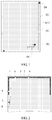
- FIG. 1 is a schematic structural diagram of a mobile phone provided with an antenna in the prior art.
- the mobile phone shown in FIG. 1 includes a metal frame 01, a circuit board 02 located in the metal frame 01, and a slot 012 formed between the metal frame 01 and the circuit board 02.
- Design of a primary antenna, a diversity antenna, and a GPS antenna in the foregoing mobile phone is as follows: Resonance is generated by the slot 012 between the metal frame 01 and the circuit board 02, and then a resonance frequency of a slot antenna is controlled by disposing a grounding point 03 and a feeding point 04 at different positions in the slot 012.
- the slot 012 controls the resonance frequency by controlling positions of the grounding point and the feeding point, but the generated resonance frequency is a main frequency and harmonic of the slot 12, which can generally be used only for designing an antenna of a single frequency band.
- the present invention provides a wireless mobile device, and the wireless mobile device has at least one slot antenna that can meet working requirements of multiple operating frequency bands, which improves compactness of a structure of the wireless mobile device.
- a wireless mobile device including a metal frame and a circuit board disposed in the metal frame, where there is a slot between at least one side edge of the circuit board and the metal frame, and further including a first grounding point, a second grounding point, a feeding point, and at least one antenna open-circuit stub, where:
- the at least one antenna open-circuit stub includes a first antenna open-circuit stub and a second antenna open-circuit stub, where a connection point of the first antenna open-circuit stub and the metal frame is located between the feeding point and the second grounding point, a connection point of the second antenna open-circuit stub and the metal frame is located between the second grounding point and the connection point of the first antenna open-circuit stub and the metal frame.
- an electrical length of the first antenna open-circuit stub is a half of an electrical length between the first grounding point and the connection point of the first antenna open-circuit stub and the metal frame.
- an electrical length of the second antenna open-circuit stub is a half of an electrical length between the first grounding point and the connection point of the second antenna open-circuit stub and the metal frame.
- a width of the slot is greater than or equal to 0.5 mm.
- the first possible implementation manner of the first aspect, the second possible implementation manner of the first aspect, the third possible implementation manner of the first aspect, or the fourth possible implementation manner of the first aspect, in a fifth possible implementation manner, that the feeding point is located between the first grounding point and the second grounding point and is connected to the circuit board and the metal frame includes:
- the first possible implementation manner of the first aspect, the second possible implementation manner of the first aspect, the third possible implementation manner of the first aspect, or the fourth possible implementation manner of the first aspect, in a sixth possible implementation manner of the first aspect, that the feeding point is located between the first grounding point and the second grounding point and is connected to the circuit board and the metal frame includes:
- a first grounding point may cooperate with a second grounding point, a feeding point, a section that is of a slot and located between the first grounding point and the second grounding point, a metal frame, and a circuit board, so that a slot antenna of a first operating frequency band can be formed.
- each antenna open-circuit stub cooperates with the first grounding point, the feeding point, a section that is of the slot and located between the first grounding point and a connection point of the antenna open-circuit stub and the metal frame, the metal frame, and the circuit board, so as to form an antenna of another resonance frequency.
- both the first operating frequency band and another operating frequency band form effective resonance by using the slot between the circuit board and the metal frame, and radiation efficiency of an antenna is not affected by the metal frame. Therefore, radiation power of the slot antenna in the foregoing wireless mobile device is relatively high in a required operating frequency band.
- the slot antenna in the foregoing wireless mobile device meets working requirements of both the first operating frequency band and an operating frequency band corresponding to each antenna open-circuit stub, which improves compactness of a structure of the wireless mobile device.
- FIG. 2 is a schematic structural diagram of a wireless mobile device provided with an antenna according to an embodiment of the present invention.
- the wireless mobile device provided in this embodiment includes a metal frame 1 and a circuit board 2 disposed in the metal frame 1, where there is a slot 3 between at least one side edge of the circuit board 2 and the metal frame 1, and the foregoing wireless mobile device further includes a first grounding point 8, a second grounding point 4, a feeding point 7, and at least one antenna open-circuit stub, for example, a first antenna open-circuit stub 6 and a second antenna open-circuit stub 5 shown in FIG. 2 .
- the first grounding point 8 is connected to the circuit board 2 and the metal frame 1
- the second grounding point 4 is connected to the circuit board 2 and the metal frame 1
- the feeding point 7 is located between the first grounding point 8 and the second grounding point 4 and is connected to the circuit board 2 and the metal frame 1.
- each antenna open-circuit stub suspends in space on an outer side of the circuit board 2, one end is connected to the metal frame 1 by crossing the slot 3, and a connection point of the antenna open-circuit stub and the metal frame 1 is located between the feeding point 7 and the second grounding point 4.
- the first grounding point 8 is disposed at a position in the slot 3 and located between the left side edge of the circuit board 2 and the metal frame 1
- the second grounding point 4 is disposed at a position in the slot and located between the upper side edge of the circuit board 2 and the metal frame 1.
- the foregoing slot 3 may be formed between the left side edge of the circuit board 2 and the metal frame 1, and both the first grounding point 8 and the second grounding point 4 are disposed in a slot (not shown in the figure) between the left side edge of the circuit board 2 and the metal frame 1.
- the first grounding point 8, the feeding point 7, the second grounding point 4, the circuit board 2, the metal frame 1, and a section that is of the slot 3 and located between the first grounding point 8 and the second grounding point 4 cooperate, so as to form a slot antenna of a first operating frequency band, and a wavelength of the first operating frequency band is specifically twice of an electrical length of a section that is of the slot 3 and used to form the slot antenna of the first operating frequency band.
- each antenna open-circuit stub cooperates with the first grounding point 8, the feeding point 7, the circuit board 2, the metal frame 1, and a section that is of the slot 3 and located between the first grounding point 8 and a connection point of the antenna open-circuit stub and the metal frame 1, so as to form a slot antenna of an operating frequency band.
- a wavelength of the operating frequency band is twice of an electrical length of a section that is of the slot 3 and located between the first grounding point 8 and the connection point of the antenna open-circuit stub and the metal frame 1.
- both the first operating frequency band and another operating frequency band form effective resonance by using the slot between the circuit board and the metal frame, and radiation efficiency of the slot antenna is not affected by the metal frame. Therefore, radiation power of the slot antenna in the foregoing wireless mobile device is relatively high in a required operating frequency band.
- the slot antenna in the foregoing wireless mobile device can meet working requirements of both the foregoing first operating frequency band and an operating frequency band corresponding to each antenna open-circuit stub, which improves compactness of a structure of the wireless mobile device.
- the at least one antenna open-circuit stub in the foregoing wireless mobile device includes the first antenna open-circuit stub 6 and the second antenna open-circuit stub 5, where a connection point of the first antenna open-circuit stub 6 and the metal frame 1 is located between the feeding point 7 and the second grounding point 4, and a connection point of the second antenna open-circuit stub 5 and the metal frame 1 is located between the second grounding point 4 and the connection point of the first antenna open-circuit stub 6 and the metal frame 1.
- an electrical length of the first antenna open-circuit stub 6 is a half of an electrical length between the first grounding point 8 and the connection point of the first antenna open-circuit stub 6 and the metal frame 1.
- An electrical length of the second antenna open-circuit stub 5 is a half of an electrical length between the first grounding point 8 and the connection point of the second antenna open-circuit stub 5 and the metal frame 1.
- the first grounding point 8 cooperates with the second grounding point 4, the feeding point 7, the section that is of the slot 3 and located between the first grounding point 8 and the second grounding point 4, the metal frame 1, and the circuit board 2, so that a GPS slot antenna with a central resonance frequency of 1.575 GHz can be formed, so as to receive a GPS signal.
- An electrical length of the section that is in the slot 3 and located between the first grounding point 8 and the second grounding point 4 is a half wavelength of the foregoing resonance frequency in the GPS antenna.
- the first antenna open-circuit stub 6 cooperates with the first grounding point 8, the feeding point 7, a section that is of the slot 3 and located between the first grounding point 8 and the connection point of the first antenna open-circuit stub 6 and the metal frame 1, the metal frame 1, and the circuit board 2, so as to form a wireless local area network antenna with a resonance frequency of 5 GHz.
- the second antenna open-circuit stub 5 cooperates with the first grounding point 8, the feeding point 7, a section that is of the slot 3 and located between the first grounding point 8 and the connection point of the second antenna open-circuit stub 5 and the metal frame 1, the metal frame 1, and the circuit board 2, so as to form a wireless local area network antenna with a resonance frequency of 2.4 GHz.
- the first grounding point 8 cooperates with the second grounding point 4, the feeding point 7, the section that is of the slot 3 and located between the first grounding point 8 and the second grounding point 4, the metal frame 1, and the circuit board 2, so as to form the slot antenna, where the resonance frequency of the slot antenna is 1.575 GHz.
- Resonance of the antenna is in a GPS frequency band, and the antenna may generate three resonances in a range from 1.4 to 6 GHz. As shown in FIG. 3 , a second mode is a wavelength, a third mode is 1.5 wavelengths, and a proportion of resonance frequencies of the three resonances is nearly 1:2:3.
- an electrical length, added in the slot 3, from the connection point of the first antenna open-circuit stub 6 and the metal frame 1 to the first grounding point 8 is a half wavelength of Wi-Fi 5 GHz, and the electrical length of the first antenna open-circuit stub 6 is a 1/4 wavelength of Wi-Fi 5 GHz.
- 1/4 wavelength impedance transformation is performed at the first antenna open-circuit stub 6, a short circuit, that is, a high current point occurs in the connection point of the first antenna open-circuit stub 6 and the metal frame 1.
- the impedance transformation causes the following: An effective grounding point of the antenna moves from the second grounding point 4 to the connection point of the first antenna open-circuit stub 6 and the metal frame 1, and an effective grounding point of another frequency does not change.
- a size of the slot antenna is reduced in terms of electricity, and the slot antenna can generate a higher resonance frequency, that is, 5 GHz.
- the second antenna open-circuit stub 5 is configured to enable the antenna to generate a resonance frequency of Wi-Fi 2.4 GHz.
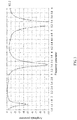
- a return loss simulation result obtained after the first antenna open-circuit stub 6 and the second antenna open-circuit stub 5 are added to the foregoing wireless mobile device is shown in FIG. 4 , and a frequency band thereof covers a GPS frequency band, Wi-Fi 2.4 GHz, Wi-Fi 5.2 GHz, and 5.8 GHz, so that the antenna of the wireless mobile device can work in these frequency bands.
- a width of the slot 3 is greater than or equal to 0.5 mm, for example, 0.5 mm, 0.55 mm, 0.6 mm, 0.7 mm, 0.75 mm, 0.8 mm, 0.9 mm, 0.95 mm, or 1 mm.
- the feeding point 7 may have a strip structure, one end of the feeding point 7 is connected to the circuit board 2, and the other end is connected to the metal frame 1. That is, the slot antenna in the wireless mobile device may directly fed by using the feeding point 7 that has a strip structure, so that an electric field at the feeding point 7 is relatively strong.
- the feeding point 7 may have a ring structure, and the feeding point 7 is disposed on the circuit board 2 and is coupled to the metal frame 1. That is, the slot antenna is fed by coupling.
Landscapes
- Engineering & Computer Science (AREA)
- Computer Networks & Wireless Communication (AREA)
- Support Of Aerials (AREA)
- Waveguide Aerials (AREA)
- Transceivers (AREA)
Applications Claiming Priority (1)
| Application Number | Priority Date | Filing Date | Title |
|---|---|---|---|
| PCT/CN2014/090091 WO2016065630A1 (zh) | 2014-10-31 | 2014-10-31 | 一种无线移动设备 |
Publications (3)
| Publication Number | Publication Date |
|---|---|
| EP3200280A1 true EP3200280A1 (de) | 2017-08-02 |
| EP3200280A4 EP3200280A4 (de) | 2017-11-08 |
| EP3200280B1 EP3200280B1 (de) | 2021-08-25 |
Family
ID=55856443
Family Applications (1)
| Application Number | Title | Priority Date | Filing Date |
|---|---|---|---|
| EP14904882.9A Active EP3200280B1 (de) | 2014-10-31 | 2014-10-31 | Drahtlose mobile vorrichtung |
Country Status (5)
| Country | Link |
|---|---|
| US (1) | US10347988B2 (de) |
| EP (1) | EP3200280B1 (de) |
| CN (1) | CN105745787B (de) |
| BR (1) | BR112017008681B1 (de) |
| WO (1) | WO2016065630A1 (de) |
Families Citing this family (10)
| Publication number | Priority date | Publication date | Assignee | Title |
|---|---|---|---|---|
| CN107464997B (zh) * | 2016-06-03 | 2020-06-02 | 北京小米移动软件有限公司 | 金属壳体及电子设备 |
| CN106252840A (zh) * | 2016-09-20 | 2016-12-21 | 北京小米移动软件有限公司 | 天线装置及终端 |
| CN106374192B (zh) * | 2016-10-25 | 2019-11-19 | 瑞声科技(南京)有限公司 | 天线组件及移动终端 |
| CN108232412B (zh) * | 2016-12-09 | 2020-04-03 | 深圳富泰宏精密工业有限公司 | 天线结构及具有该天线结构的无线通信装置 |
| CN106848594B (zh) * | 2017-03-06 | 2019-10-11 | 北京小米移动软件有限公司 | 天线模块及电子设备 |
| EP3682507B1 (de) | 2017-10-05 | 2023-10-04 | Huawei Technologies Co., Ltd. | Antennensystem für eine drahtlose kommunikationsvorrichtung |
| CN108288767B (zh) * | 2017-12-29 | 2021-06-01 | 瑞声精密制造科技(常州)有限公司 | 天线系统及移动终端 |
| CN111146570B (zh) * | 2018-11-02 | 2022-08-23 | 青岛海信移动通信技术股份有限公司 | 一种具有可重构天线的终端 |
| CN109742513A (zh) * | 2018-12-31 | 2019-05-10 | 瑞声科技(南京)有限公司 | Mimo天线系统 |
| US12212059B2 (en) * | 2021-04-21 | 2025-01-28 | Dell Products Lp | System and method for operating a partitioned antenna at a vent formed in a bottom metal chassis |
Family Cites Families (10)
| Publication number | Priority date | Publication date | Assignee | Title |
|---|---|---|---|---|
| JP2002314330A (ja) * | 2001-04-10 | 2002-10-25 | Murata Mfg Co Ltd | アンテナ装置 |
| JP3930477B2 (ja) * | 2001-10-11 | 2007-06-13 | 太陽誘電株式会社 | 誘電体アンテナ |
| US6965346B2 (en) | 2002-12-16 | 2005-11-15 | Samsung Electro-Mechanics Co., Ltd. | Wireless LAN antenna and wireless LAN card with the same |
| US7710338B2 (en) * | 2007-05-08 | 2010-05-04 | Panasonic Corporation | Slot antenna apparatus eliminating unstable radiation due to grounding structure |
| US7551142B1 (en) | 2007-12-13 | 2009-06-23 | Apple Inc. | Hybrid antennas with directly fed antenna slots for handheld electronic devices |
| CN101938033A (zh) * | 2009-06-30 | 2011-01-05 | 宏达国际电子股份有限公司 | 无线通信装置 |
| US8542154B2 (en) * | 2009-07-02 | 2013-09-24 | Lg Electronics Inc. | Portable terminal |
| CN202977704U (zh) * | 2012-11-01 | 2013-06-05 | 耀登科技股份有限公司 | 抗金属边框手机的天线结构 |
| US8963785B2 (en) * | 2012-12-27 | 2015-02-24 | Auden Techno. Corp. | Antenna structure for using with a metal frame of a mobile phone |
| CN103296385B (zh) * | 2013-05-29 | 2016-05-11 | 上海安费诺永亿通讯电子有限公司 | 一种可调式多频天线系统 |
-
2014
- 2014-10-31 BR BR112017008681-6A patent/BR112017008681B1/pt not_active IP Right Cessation
- 2014-10-31 US US15/523,227 patent/US10347988B2/en active Active
- 2014-10-31 CN CN201480047676.4A patent/CN105745787B/zh active Active
- 2014-10-31 EP EP14904882.9A patent/EP3200280B1/de active Active
- 2014-10-31 WO PCT/CN2014/090091 patent/WO2016065630A1/zh not_active Ceased
Also Published As
| Publication number | Publication date |
|---|---|
| US20170331189A1 (en) | 2017-11-16 |
| EP3200280A4 (de) | 2017-11-08 |
| EP3200280B1 (de) | 2021-08-25 |
| CN105745787A (zh) | 2016-07-06 |
| WO2016065630A1 (zh) | 2016-05-06 |
| BR112017008681A2 (pt) | 2018-07-24 |
| US10347988B2 (en) | 2019-07-09 |
| BR112017008681A8 (pt) | 2022-08-02 |
| CN105745787B (zh) | 2019-08-16 |
| BR112017008681B1 (pt) | 2022-10-04 |
Similar Documents
| Publication | Publication Date | Title |
|---|---|---|
| EP3200280B1 (de) | Drahtlose mobile vorrichtung | |
| US11855343B2 (en) | Antenna and mobile terminal | |
| US10601116B2 (en) | Wireless terminal | |
| EP2858171A1 (de) | Leiterplattenantenne und endgerät damit | |
| EP2892108A1 (de) | Versorgungsnetz, antenne und speiseschaltung für eine dualpolarisierte gruppenantenne | |
| EP3157098A1 (de) | Mobiles endgerät | |
| CN101877433B (zh) | 多频天线及应用该多频天线的无线通信装置 | |
| EP2851997A1 (de) | Leiterplattenantenne und leiterplatte | |
| EP3300170B1 (de) | Antenne und benutzerausrüstung | |
| US10109926B2 (en) | Antenna radiator, antenna and mobile terminal | |
| CN203481380U (zh) | 用于移动终端的天线、移动终端外壳和移动终端 | |
| CN103633419A (zh) | 移动装置 | |
| EP2760079B1 (de) | Bestückte leiterplatte für ein drahtloses endgerät und drahtloses endgerät | |
| CN105322278A (zh) | 具有连续金属框的天线及其电子设备 | |
| WO2016161653A1 (zh) | 一种多频天线及终端设备 | |
| CN106876990B (zh) | 一种移动终端的天线及移动终端 | |
| CN105449349A (zh) | 一种宽频带4g无线终端天线 | |
| US10305169B2 (en) | Antenna apparatus and terminal |
Legal Events
| Date | Code | Title | Description |
|---|---|---|---|
| STAA | Information on the status of an ep patent application or granted ep patent |
Free format text: STATUS: THE INTERNATIONAL PUBLICATION HAS BEEN MADE |
|
| PUAI | Public reference made under article 153(3) epc to a published international application that has entered the european phase |
Free format text: ORIGINAL CODE: 0009012 |
|
| STAA | Information on the status of an ep patent application or granted ep patent |
Free format text: STATUS: REQUEST FOR EXAMINATION WAS MADE |
|
| 17P | Request for examination filed |
Effective date: 20170427 |
|
| AK | Designated contracting states |
Kind code of ref document: A1 Designated state(s): AL AT BE BG CH CY CZ DE DK EE ES FI FR GB GR HR HU IE IS IT LI LT LU LV MC MK MT NL NO PL PT RO RS SE SI SK SM TR |
|
| AX | Request for extension of the european patent |
Extension state: BA ME |
|
| A4 | Supplementary search report drawn up and despatched |
Effective date: 20171006 |
|
| RIC1 | Information provided on ipc code assigned before grant |
Ipc: H01Q 13/10 20060101ALI20170929BHEP Ipc: H01Q 5/378 20150101ALI20170929BHEP Ipc: H01Q 5/371 20150101AFI20170929BHEP Ipc: H01Q 1/24 20060101ALI20170929BHEP Ipc: H01Q 9/04 20060101ALI20170929BHEP |
|
| DAX | Request for extension of the european patent (deleted) | ||
| RIN1 | Information on inventor provided before grant (corrected) |
Inventor name: WANG, LEI Inventor name: WANG, HANYANG Inventor name: LV, SHUWEN Inventor name: CHEN, LINA Inventor name: WANG, HONGYU Inventor name: XU, HUILIANG Inventor name: LEE, CHIEN-MING |
|
| REG | Reference to a national code |
Ref country code: DE Ref legal event code: R079 Ref document number: 602014079767 Country of ref document: DE Free format text: PREVIOUS MAIN CLASS: H01Q0005371000 Ipc: H01Q0001240000 |
|
| RIC1 | Information provided on ipc code assigned before grant |
Ipc: H01Q 13/10 20060101ALI20210211BHEP Ipc: H01Q 1/24 20060101AFI20210211BHEP Ipc: H01Q 5/378 20150101ALI20210211BHEP Ipc: H01Q 5/364 20150101ALI20210211BHEP Ipc: H01Q 5/371 20150101ALI20210211BHEP |
|
| GRAP | Despatch of communication of intention to grant a patent |
Free format text: ORIGINAL CODE: EPIDOSNIGR1 |
|
| STAA | Information on the status of an ep patent application or granted ep patent |
Free format text: STATUS: GRANT OF PATENT IS INTENDED |
|
| INTG | Intention to grant announced |
Effective date: 20210325 |
|
| GRAS | Grant fee paid |
Free format text: ORIGINAL CODE: EPIDOSNIGR3 |
|
| GRAA | (expected) grant |
Free format text: ORIGINAL CODE: 0009210 |
|
| STAA | Information on the status of an ep patent application or granted ep patent |
Free format text: STATUS: THE PATENT HAS BEEN GRANTED |
|
| AK | Designated contracting states |
Kind code of ref document: B1 Designated state(s): AL AT BE BG CH CY CZ DE DK EE ES FI FR GB GR HR HU IE IS IT LI LT LU LV MC MK MT NL NO PL PT RO RS SE SI SK SM TR |
|
| REG | Reference to a national code |
Ref country code: CH Ref legal event code: EP |
|
| REG | Reference to a national code |
Ref country code: DE Ref legal event code: R096 Ref document number: 602014079767 Country of ref document: DE |
|
| REG | Reference to a national code |
Ref country code: IE Ref legal event code: FG4D Ref country code: AT Ref legal event code: REF Ref document number: 1424743 Country of ref document: AT Kind code of ref document: T Effective date: 20210915 |
|
| REG | Reference to a national code |
Ref country code: NL Ref legal event code: FP |
|
| REG | Reference to a national code |
Ref country code: LT Ref legal event code: MG9D |
|
| REG | Reference to a national code |
Ref country code: AT Ref legal event code: MK05 Ref document number: 1424743 Country of ref document: AT Kind code of ref document: T Effective date: 20210825 |
|
| PG25 | Lapsed in a contracting state [announced via postgrant information from national office to epo] |
Ref country code: HR Free format text: LAPSE BECAUSE OF FAILURE TO SUBMIT A TRANSLATION OF THE DESCRIPTION OR TO PAY THE FEE WITHIN THE PRESCRIBED TIME-LIMIT Effective date: 20210825 Ref country code: RS Free format text: LAPSE BECAUSE OF FAILURE TO SUBMIT A TRANSLATION OF THE DESCRIPTION OR TO PAY THE FEE WITHIN THE PRESCRIBED TIME-LIMIT Effective date: 20210825 Ref country code: SE Free format text: LAPSE BECAUSE OF FAILURE TO SUBMIT A TRANSLATION OF THE DESCRIPTION OR TO PAY THE FEE WITHIN THE PRESCRIBED TIME-LIMIT Effective date: 20210825 Ref country code: LT Free format text: LAPSE BECAUSE OF FAILURE TO SUBMIT A TRANSLATION OF THE DESCRIPTION OR TO PAY THE FEE WITHIN THE PRESCRIBED TIME-LIMIT Effective date: 20210825 Ref country code: BG Free format text: LAPSE BECAUSE OF FAILURE TO SUBMIT A TRANSLATION OF THE DESCRIPTION OR TO PAY THE FEE WITHIN THE PRESCRIBED TIME-LIMIT Effective date: 20211125 Ref country code: AT Free format text: LAPSE BECAUSE OF FAILURE TO SUBMIT A TRANSLATION OF THE DESCRIPTION OR TO PAY THE FEE WITHIN THE PRESCRIBED TIME-LIMIT Effective date: 20210825 Ref country code: PT Free format text: LAPSE BECAUSE OF FAILURE TO SUBMIT A TRANSLATION OF THE DESCRIPTION OR TO PAY THE FEE WITHIN THE PRESCRIBED TIME-LIMIT Effective date: 20211227 Ref country code: NO Free format text: LAPSE BECAUSE OF FAILURE TO SUBMIT A TRANSLATION OF THE DESCRIPTION OR TO PAY THE FEE WITHIN THE PRESCRIBED TIME-LIMIT Effective date: 20211125 Ref country code: FI Free format text: LAPSE BECAUSE OF FAILURE TO SUBMIT A TRANSLATION OF THE DESCRIPTION OR TO PAY THE FEE WITHIN THE PRESCRIBED TIME-LIMIT Effective date: 20210825 Ref country code: ES Free format text: LAPSE BECAUSE OF FAILURE TO SUBMIT A TRANSLATION OF THE DESCRIPTION OR TO PAY THE FEE WITHIN THE PRESCRIBED TIME-LIMIT Effective date: 20210825 |
|
| PG25 | Lapsed in a contracting state [announced via postgrant information from national office to epo] |
Ref country code: PL Free format text: LAPSE BECAUSE OF FAILURE TO SUBMIT A TRANSLATION OF THE DESCRIPTION OR TO PAY THE FEE WITHIN THE PRESCRIBED TIME-LIMIT Effective date: 20210825 Ref country code: LV Free format text: LAPSE BECAUSE OF FAILURE TO SUBMIT A TRANSLATION OF THE DESCRIPTION OR TO PAY THE FEE WITHIN THE PRESCRIBED TIME-LIMIT Effective date: 20210825 Ref country code: GR Free format text: LAPSE BECAUSE OF FAILURE TO SUBMIT A TRANSLATION OF THE DESCRIPTION OR TO PAY THE FEE WITHIN THE PRESCRIBED TIME-LIMIT Effective date: 20211126 |
|
| PG25 | Lapsed in a contracting state [announced via postgrant information from national office to epo] |
Ref country code: DK Free format text: LAPSE BECAUSE OF FAILURE TO SUBMIT A TRANSLATION OF THE DESCRIPTION OR TO PAY THE FEE WITHIN THE PRESCRIBED TIME-LIMIT Effective date: 20210825 |
|
| REG | Reference to a national code |
Ref country code: DE Ref legal event code: R097 Ref document number: 602014079767 Country of ref document: DE |
|
| PG25 | Lapsed in a contracting state [announced via postgrant information from national office to epo] |
Ref country code: SM Free format text: LAPSE BECAUSE OF FAILURE TO SUBMIT A TRANSLATION OF THE DESCRIPTION OR TO PAY THE FEE WITHIN THE PRESCRIBED TIME-LIMIT Effective date: 20210825 Ref country code: SK Free format text: LAPSE BECAUSE OF FAILURE TO SUBMIT A TRANSLATION OF THE DESCRIPTION OR TO PAY THE FEE WITHIN THE PRESCRIBED TIME-LIMIT Effective date: 20210825 Ref country code: RO Free format text: LAPSE BECAUSE OF FAILURE TO SUBMIT A TRANSLATION OF THE DESCRIPTION OR TO PAY THE FEE WITHIN THE PRESCRIBED TIME-LIMIT Effective date: 20210825 Ref country code: EE Free format text: LAPSE BECAUSE OF FAILURE TO SUBMIT A TRANSLATION OF THE DESCRIPTION OR TO PAY THE FEE WITHIN THE PRESCRIBED TIME-LIMIT Effective date: 20210825 Ref country code: CZ Free format text: LAPSE BECAUSE OF FAILURE TO SUBMIT A TRANSLATION OF THE DESCRIPTION OR TO PAY THE FEE WITHIN THE PRESCRIBED TIME-LIMIT Effective date: 20210825 Ref country code: AL Free format text: LAPSE BECAUSE OF FAILURE TO SUBMIT A TRANSLATION OF THE DESCRIPTION OR TO PAY THE FEE WITHIN THE PRESCRIBED TIME-LIMIT Effective date: 20210825 |
|
| REG | Reference to a national code |
Ref country code: CH Ref legal event code: PL |
|
| REG | Reference to a national code |
Ref country code: BE Ref legal event code: MM Effective date: 20211031 |
|
| PG25 | Lapsed in a contracting state [announced via postgrant information from national office to epo] |
Ref country code: MC Free format text: LAPSE BECAUSE OF FAILURE TO SUBMIT A TRANSLATION OF THE DESCRIPTION OR TO PAY THE FEE WITHIN THE PRESCRIBED TIME-LIMIT Effective date: 20210825 |
|
| PLBE | No opposition filed within time limit |
Free format text: ORIGINAL CODE: 0009261 |
|
| STAA | Information on the status of an ep patent application or granted ep patent |
Free format text: STATUS: NO OPPOSITION FILED WITHIN TIME LIMIT |
|
| PG25 | Lapsed in a contracting state [announced via postgrant information from national office to epo] |
Ref country code: LU Free format text: LAPSE BECAUSE OF NON-PAYMENT OF DUE FEES Effective date: 20211031 Ref country code: IT Free format text: LAPSE BECAUSE OF FAILURE TO SUBMIT A TRANSLATION OF THE DESCRIPTION OR TO PAY THE FEE WITHIN THE PRESCRIBED TIME-LIMIT Effective date: 20210825 Ref country code: BE Free format text: LAPSE BECAUSE OF NON-PAYMENT OF DUE FEES Effective date: 20211031 |
|
| 26N | No opposition filed |
Effective date: 20220527 |
|
| PG25 | Lapsed in a contracting state [announced via postgrant information from national office to epo] |
Ref country code: SI Free format text: LAPSE BECAUSE OF FAILURE TO SUBMIT A TRANSLATION OF THE DESCRIPTION OR TO PAY THE FEE WITHIN THE PRESCRIBED TIME-LIMIT Effective date: 20210825 Ref country code: LI Free format text: LAPSE BECAUSE OF NON-PAYMENT OF DUE FEES Effective date: 20211031 Ref country code: CH Free format text: LAPSE BECAUSE OF NON-PAYMENT OF DUE FEES Effective date: 20211031 |
|
| PG25 | Lapsed in a contracting state [announced via postgrant information from national office to epo] |
Ref country code: IE Free format text: LAPSE BECAUSE OF NON-PAYMENT OF DUE FEES Effective date: 20211031 |
|
| PG25 | Lapsed in a contracting state [announced via postgrant information from national office to epo] |
Ref country code: HU Free format text: LAPSE BECAUSE OF FAILURE TO SUBMIT A TRANSLATION OF THE DESCRIPTION OR TO PAY THE FEE WITHIN THE PRESCRIBED TIME-LIMIT; INVALID AB INITIO Effective date: 20141031 |
|
| PG25 | Lapsed in a contracting state [announced via postgrant information from national office to epo] |
Ref country code: CY Free format text: LAPSE BECAUSE OF FAILURE TO SUBMIT A TRANSLATION OF THE DESCRIPTION OR TO PAY THE FEE WITHIN THE PRESCRIBED TIME-LIMIT Effective date: 20210825 |
|
| PG25 | Lapsed in a contracting state [announced via postgrant information from national office to epo] |
Ref country code: MK Free format text: LAPSE BECAUSE OF FAILURE TO SUBMIT A TRANSLATION OF THE DESCRIPTION OR TO PAY THE FEE WITHIN THE PRESCRIBED TIME-LIMIT Effective date: 20210825 |
|
| PG25 | Lapsed in a contracting state [announced via postgrant information from national office to epo] |
Ref country code: TR Free format text: LAPSE BECAUSE OF FAILURE TO SUBMIT A TRANSLATION OF THE DESCRIPTION OR TO PAY THE FEE WITHIN THE PRESCRIBED TIME-LIMIT Effective date: 20210825 |
|
| PG25 | Lapsed in a contracting state [announced via postgrant information from national office to epo] |
Ref country code: MT Free format text: LAPSE BECAUSE OF FAILURE TO SUBMIT A TRANSLATION OF THE DESCRIPTION OR TO PAY THE FEE WITHIN THE PRESCRIBED TIME-LIMIT Effective date: 20210825 |
|
| PGFP | Annual fee paid to national office [announced via postgrant information from national office to epo] |
Ref country code: NL Payment date: 20250912 Year of fee payment: 12 |
|
| PGFP | Annual fee paid to national office [announced via postgrant information from national office to epo] |
Ref country code: GB Payment date: 20250911 Year of fee payment: 12 |
|
| PGFP | Annual fee paid to national office [announced via postgrant information from national office to epo] |
Ref country code: FR Payment date: 20250908 Year of fee payment: 12 |
|
| PGFP | Annual fee paid to national office [announced via postgrant information from national office to epo] |
Ref country code: DE Payment date: 20250902 Year of fee payment: 12 |