EP3200293A1 - Agencement d'un tiroir de commutation électrique et son logement fixe - Google Patents
Agencement d'un tiroir de commutation électrique et son logement fixe Download PDFInfo
- Publication number
- EP3200293A1 EP3200293A1 EP16152765.0A EP16152765A EP3200293A1 EP 3200293 A1 EP3200293 A1 EP 3200293A1 EP 16152765 A EP16152765 A EP 16152765A EP 3200293 A1 EP3200293 A1 EP 3200293A1
- Authority
- EP
- European Patent Office
- Prior art keywords
- adapter
- contacts
- electrical
- receptacle
- arrangement according
- Prior art date
- Legal status (The legal status is an assumption and is not a legal conclusion. Google has not performed a legal analysis and makes no representation as to the accuracy of the status listed.)
- Withdrawn
Links
- 238000003780 insertion Methods 0.000 claims abstract description 19
- 230000037431 insertion Effects 0.000 claims abstract description 19
- 239000002184 metal Substances 0.000 claims description 16
- 230000000295 complement effect Effects 0.000 description 2
- 238000009434 installation Methods 0.000 description 2
- FGRBYDKOBBBPOI-UHFFFAOYSA-N 10,10-dioxo-2-[4-(N-phenylanilino)phenyl]thioxanthen-9-one Chemical compound O=C1c2ccccc2S(=O)(=O)c2ccc(cc12)-c1ccc(cc1)N(c1ccccc1)c1ccccc1 FGRBYDKOBBBPOI-UHFFFAOYSA-N 0.000 description 1
- 230000004888 barrier function Effects 0.000 description 1
- 230000009286 beneficial effect Effects 0.000 description 1
- 230000015572 biosynthetic process Effects 0.000 description 1
- 230000001419 dependent effect Effects 0.000 description 1
- 230000006872 improvement Effects 0.000 description 1
- 238000002347 injection Methods 0.000 description 1
- 239000007924 injection Substances 0.000 description 1
- 230000013011 mating Effects 0.000 description 1
- 230000007246 mechanism Effects 0.000 description 1
Images


Classifications
-
- H—ELECTRICITY
- H02—GENERATION; CONVERSION OR DISTRIBUTION OF ELECTRIC POWER
- H02B—BOARDS, SUBSTATIONS OR SWITCHING ARRANGEMENTS FOR THE SUPPLY OR DISTRIBUTION OF ELECTRIC POWER
- H02B1/00—Frameworks, boards, panels, desks, casings; Details of substations or switching arrangements
- H02B1/26—Casings; Parts thereof or accessories therefor
- H02B1/30—Cabinet-type casings; Parts thereof or accessories therefor
- H02B1/32—Mounting of devices therein
- H02B1/34—Racks
- H02B1/36—Racks with withdrawable units
-
- H—ELECTRICITY
- H02—GENERATION; CONVERSION OR DISTRIBUTION OF ELECTRIC POWER
- H02B—BOARDS, SUBSTATIONS OR SWITCHING ARRANGEMENTS FOR THE SUPPLY OR DISTRIBUTION OF ELECTRIC POWER
- H02B1/00—Frameworks, boards, panels, desks, casings; Details of substations or switching arrangements
- H02B1/20—Bus-bar or other wiring layouts, e.g. in cubicles, in switchyards
- H02B1/202—Cable lay-outs
-
- H—ELECTRICITY
- H02—GENERATION; CONVERSION OR DISTRIBUTION OF ELECTRIC POWER
- H02B—BOARDS, SUBSTATIONS OR SWITCHING ARRANGEMENTS FOR THE SUPPLY OR DISTRIBUTION OF ELECTRIC POWER
- H02B1/00—Frameworks, boards, panels, desks, casings; Details of substations or switching arrangements
- H02B1/20—Bus-bar or other wiring layouts, e.g. in cubicles, in switchyards
- H02B1/21—Bus-bar arrangements for rack-mounted devices with withdrawable units
Definitions
- the invention relates to an arrangement of an electrical switching strip and a stationary receptacle for one end of the switching strip, wherein the switching strip is mounted retractably in the receptacle and in the insertion direction leading multiple contacts for attachment to electrical rails, and the safety edge in the direction of insertion laterally, in the area End of the safety edge, having electrical outlets.
- control cabinets It is known to equip control cabinets with a variety of electrical switching strips, which are designed for example as load disconnectors with NH fuses.
- a busbar system is arranged, with which the switching strips are connectable.
- the safety edges can be inserted into receptacles of the control cabinets and have in the direction of insertion leading contacts according to the number of busbars, for mounting on the busbars.
- the electrical outlets of the respective safety edges are positioned differently.
- the electrical outlets are the same as the contacts for plugging on the busbars in, arranged in the insertion direction leading edge area of the safety edge and it will be these outlets when inserting the safety edge on mating contacts plugged.
- This Doppelsteck sadness thus pluggability of electrical inputs and electrical outlets, can be realized only in specially designed on this variant training of the cabinet.
- the electrical outlets of the switching strips are led out laterally from these, with the electrical outlets external power cable by means of screw-clamp connections can be fastened. Consequently, in this variant, the assembly and / or disassembly of the respective safety edge very expensive.
- cabinet profiles are used made of metal, which are used for the storage of recordings for the safety edges. On opposite sides of the respective safety edge this is inserted in receptacles inserted, these recordings are stored in the cabinet profiles.
- An electrical safety edge is basically in the DE 196 17 260 C1 described.
- the object of the invention is to form an arrangement of the type mentioned so that a simple, safe and time-saving installation and / or disassembly of the electrical switching strip, based both on their storage and their electrical functions, is possible.
- the electrical outlets of the switching strip are designed as plug contacts and the stationary receptacle receives an adapter, the switchboard side is provided with electrical contacts for the insertable into these electrical contacts plug contacts.
- This adapter is provided with electrical outlets which are electrically connected to the electrical contacts of the adapter.
- the arrangement according to the invention enables double insertion, thus a plug-in both the input side to the electrical rails and the output side to the electrical contacts of the adapter. Since the plug-in takes place on the output side to the side, thus over the adapter associated with the stationary receptacle, the arrangement according to the invention can be realized in a barrier-independent manner. It is only necessary to position in an electrical cabinet, especially electrical cabinet, recordings that serve the insertion of the safety edges, with two receptacles per safety edge on opposite sides of the safety edge are sufficient. One of the recordings, namely the one which is assigned to the output side plug contacts of the safety edge, receives the adapter, via which the output side contacting is effected.
- the electrical outlets of the adapter can be designed in different ways. For example, the electrical outlets are designed as power cable connections or designed so that they interact with outgoing busbars.
- the distance of the rails of an input-side busbar system can be arbitrary and quite different.
- the safety edge Due to the double pluggability of the safety edge, it can be mounted or removed by simply inserting or removing it. It is a simple, safe and time-saving assembly and / or disassembly of electrical Safety edge, based both on their storage, as well as on their electrical function, possible.
- the rails to which the safety edge in the insertion direction can be plugged forward to rails of an electrical busbar system.
- the respective switching strip are assigned two to four rails for corresponding current phases.
- the safety edge in the region of opposite ends is mounted retractable.
- the switching strip in the region of one end in the stationary receptacle which receives the adapter stored.
- the safety edge is mounted in a stationary receptacle, which is not assigned to an adapter.
- the two stationary receptacles are designed identically for the respective switching strip. The difference between the two stationary recordings is only in their purpose, with the one stationary receiving the adapter.
- the receptacle or the two receptacles are mounted in a cabinet, in particular in cupboard profiles of the cabinet.
- This cabinet is in particular a control cabinet.
- the recording or the two recordings for the respective switching strip can be stored in different ways in the cabinet.
- the receptacle or the two receptacles in the cabinet in particular in the cabinet profiles, can be inserted, in particular latched, and / or screwed.
- a particularly simple design results for the receptacle for the adapter when the receptacle is shaped like a frame. In principle, it is not necessary for the receptacle and the adapter assigned to it to represent separate components. But such is considered beneficial.
- the adapter passes through an opening in the receptacle for the adapter.
- the adapter and associated with this recording can be connected to each other in a variety of ways when they represent separate components. It is considered to be particularly advantageous if the adapter is held positively and / or latching and / or screwed in the receptacle for the adapter and / or cabinet profiles. As a rule, it is sufficient if the adapter is held exclusively in the receptacle for this, because the receptacle itself is held securely in the cabinet or cabinet profiles.
- the electrical outlets of the adapter can be designed differently. It is considered to be particularly advantageous if the electrical outlets of the adapter are designed as power cable connections. With these power cable connections outgoing power cable are connected, in particular by means of clamp-screw connections connected so that the power cables are electrically connected via the power cable connections to the switchboard-side electrical contacts of the adapter. After this basic installation, it is necessary for electrical connection of the switching strip, only to insert these, in particular in the two arranged on opposite sides of the switching strip stationary receptacles for the associated ends of the switching strip, the switching edge on the input side contacts the rails and the output side via the electrical Departures in the form of plug contacts is electrically connected to the adapter.
- the adapter has a current-carrying unit which has the current-carrying contacts of the adapter, the power cable connections and the electrical connections of these contacts and connections, and a non-conductive housing is provided in the region of these contacts.
- This housing also ensures a contact protection in the area of these contacts, in particular a finger-safe contact protection (IP2x).
- IP2x finger-safe contact protection
- the outlet-side plug contacts of the switching strip are formed in particular as mutually parallel plate-shaped contacts and it is the switchboard side electrical contacts of the adapter formed as sockets for receiving the respective plate-shaped contact between two legs of the socket. This makes it possible to accomplish a very simple mounting or dismounting of the safety edge in the region of the adapter.
- a cover housing for the power cable connections can be connected to the adapter, in particular the housing of the adapter, wherein the cover housing has bushings for connectable to the power cable connections power cable.
- the cabinet in particular the cabinet, form when cabinet profiles are used, which are provided as sheet metal profiles with a hole pattern, for the purpose of arrangement and storage of recording or recordings in variable positions with respect to the sheet metal profiles.
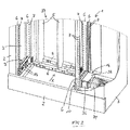
- the Fig. 1 and 2 show the lower portion of an electrical cabinet 1, which has a front 2, side walls 3, a rear wall 4 and a lid, not shown.
- an electrical busbar system is arranged in the region of the rear wall 4, which is formed of three parallel to each other and in the embodiment at the same distance from each other arranged bus bars 5, which, vertically in the Length and perpendicular in their width, to the rear wall 4 extend.
- the control cabinet 1 is divided into a slide-in space 37 for a plurality of safety edges and a connection space 38 located next to the insertion space 37, in which the safety edges are connected on the outlet side.
- cabinet 1 structural elements are installed. These are made of metal, vertically arranged sheet metal profiles 6 with holes 7 to form a hole pattern, further to horizontally arranged flat positioning 8, which serve to position the busbars 5 and possibly other to be arranged within the cabinet 1 functional elements.
- the sheet metal profiles allow the arrangement of functional components of the control cabinet 1 in the desired height, taking into account the hole pattern.
- Fig. 1 and 2 In the on the orientation of the Fig. 1 and 2 relative left portion of the cabinet 1, two vertically arranged sheet metal profiles 6 are positioned, which serve the storage of various recordings 9 one above the other, wherein only one, namely the lowermost receptacle 9, is illustrated. At a distance of about one third of the width of the cabinet 1, seen from the right side wall 3, form two more sheet metal profiles 6 the camp for a variety of shots, of which in turn only the bottom shot 10 is illustrated.
- the receptacles 9 and 10 are formed as plastic injection molded parts and designed identically. They are arranged with respect to a running between these vertical plane mirror-symmetrical and horizontally oriented and are used for the displaceable storage of a safety edge 11, as shown in the Fig. 5 is shown, in the region of the opposite ends 12, 13th
- electrical switching strip 11 is a switchable load-disconnector with three NH fuses, which are each assigned to one of the three phases of the busbar system. Switching the switching strip 11 via a manually operable lever 24, which serves to trigger a switching mechanism of the switching strip 11.
- the insertion direction the safety edge 11 when guided by the two receptacles 9 and 10, is in the Fig. 1-5 illustrated by the arrow X.
- the switching strip 11 has in the insertion direction X leading three formed as a socket contacts 14 for attachment to the bus bars 5.
- the respective busbar 5 is clamped between two legs 15 of the respective contact 14.
- the contacts 14 thus form the input contacts for contacting the busbar system of the cabinet 1.
- the switching strip 11 In the region of the end 13, which is associated with the receptacle 10, the switching strip 11 on three electrical outlets, which are designed as plug contacts 16.
- the plug contacts 16 are formed as outgoing busbars of the switching strip 11.
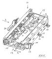
- FIG. 1 to 4 The representation of the Fig. 1 to 4 It can be seen that the respective receptacle 9 or 10 are formed like a frame and in the receptacle 9 and 10, an opening 17 is formed. This opening 17 passes through the receptacle 10 an adapter 18. Illustrated by the arrow X in these figures, the insertion direction of the safety edge 11. This is guided over guide surfaces 19 of the receptacles 9, 10 vertically and laterally.
- the respective receptacle 9 or 10 is provided on its the sheet metal profiles 6 facing sides with correspondingly arranged the perforated grid knob-like projections which are 9 and 10 to the sheet metal profiles 6 in the nubs associated holes 7 of the sheet metal profiles 6 inserted at a defined positioning of the receptacle ,
- an additional connection of receptacle 9 or 10 and sheet metal profiles 6 may be provided by means of fastening elements, in particular by means of screws 39.
- the respective receptacle. 9 or 10 is connected to a particular 16-pin auxiliary power connector 22, the inserted with the switching strip 11 with a complementary 16-pole auxiliary power connector 23 (see Fig. 5 ) of the switching strip 11 cooperates, for controlling a possibly built-in accessories (converter, switch position display, etc.).
- 3 and 4 illustrate the special conditions in the area of the receptacle 10, which cooperates with the adapter 18.
- This adapter 18 has switchboard side three trained as sockets electrical contacts 25 for the insertable into these contacts 25 plate-shaped plug contacts 16 of the switching strip 11.
- the U-shaped contacts 25 thus extend in the opening direction of the U against the insertion direction X of the switching strip 11.
- the adapter 18 is further provided with three electrical outlets 26 which are electrically connected to the electrical contacts 25, in particular via a rail.
- adapter 18 and receptacle 10 of the adapter For connecting adapter 18 and receptacle 10 of the adapter is inserted into the opening 17 of the receptacle 10, as far as a projecting circumferential edge 27 of the adapter 18 abuts against bottom plates 20 of the receptacle 10 and in this position, two locking elements 28 of the adapter 18 with complementary Snap locking elements of the receptacle 10.
- the locking elements 28 are arranged on the top and bottom of the adapter 18 substantially diametrically opposite each other.
- one or more screw connections for connecting adapter 18 and sheet metal profile 6 are additionally provided. Illustrated is a fastening screw 29.
- screw connections for connecting adapter 18 and receptacle 10, illustrated by the screws 21, are provided.
- the electrical outlets 26 of the adapter 18 are designed as power cable connections. They have terminals with screws 30 for clamping three power cables.
- the adapter 18 has the current-carrying unit, the current-carrying contacts 25 of the adapter, the power cable terminals 26 and the electrical connections, which has the contacts 25 and terminals 26, and a non-conductive housing 31 in the region of the contacts 25.
- the housing 31 is provided with three slots 40 for the insertion of the plug contacts 16 of the switching strip 11 for the purpose of attaching the plug contacts 16 to the contacts 25 of the adapter 18.
- the housing 31 is connectable to a housing 32 for the power cable terminals 26. Hereby points the housing 32 bushings 33 for connectable to the power cable terminals 26 power cable.
- the power cables each pass through a cable protection 34, which can be plugged onto lugs 35 of the housing 32.
- the three outgoing side, not illustrated power cables are touch safe - finger safe - out to the adapter 18 and it is also the projecting into the cabinet interior end of the adapter 18 touch safe - finger safe - protected by the housing 31.
- the housing 32 is provided with a lid 36. When the cover 36 is open, the interior of the housing 32 is accessible.
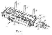
- Fig. 6 shows the arrangement of the inserted into the two receptacles 9, 10 electrical switching strip 11 and the busbar system with the three busbars 5 and the receptacle 10 associated adapter 18 with its current drains, thus without the cabinet 1 as such.
- the described design of the control cabinet 1 makes it easy to mount the respective electrical switching strip 11 by the safety edge 11 is inserted into the two receptacles 9, 10 and guided by this. Upon reaching the maximum insertion position of the switching strip 11 contact both the contacts 14 of the switching strip 11, the busbars 5 and the plug contacts 16 of the switching strip 11, the contacts 25 of the adapter. To mount the safety edge 11, it is not necessary to perform actions on the outlet side of the adapter 18. This also applies accordingly to the disassembly of the safety edge 11. It is only necessary to pull the safety edge 11 against the direction of the arrow X from the receptacles 9, 10, whereby the contacting of the switching strip 11 is canceled input and output side.
- the formation of the contacts of the switching strip 11 and adapter 18 is not limited to the illustrated embodiment. Thus, instead of a plate-shaped contact, a socket contact can be provided, which then interacts with a plate-shaped contact.
Landscapes
- Engineering & Computer Science (AREA)
- Power Engineering (AREA)
- Patch Boards (AREA)
Priority Applications (2)
| Application Number | Priority Date | Filing Date | Title |
|---|---|---|---|
| EP16152765.0A EP3200293A1 (fr) | 2016-01-26 | 2016-01-26 | Agencement d'un tiroir de commutation électrique et son logement fixe |
| EP17152235.2A EP3200294B1 (fr) | 2016-01-26 | 2017-01-19 | Agencement d'une tiroir de commutation électrique et son logement fixe |
Applications Claiming Priority (1)
| Application Number | Priority Date | Filing Date | Title |
|---|---|---|---|
| EP16152765.0A EP3200293A1 (fr) | 2016-01-26 | 2016-01-26 | Agencement d'un tiroir de commutation électrique et son logement fixe |
Publications (1)
| Publication Number | Publication Date |
|---|---|
| EP3200293A1 true EP3200293A1 (fr) | 2017-08-02 |
Family
ID=55262708
Family Applications (2)
| Application Number | Title | Priority Date | Filing Date |
|---|---|---|---|
| EP16152765.0A Withdrawn EP3200293A1 (fr) | 2016-01-26 | 2016-01-26 | Agencement d'un tiroir de commutation électrique et son logement fixe |
| EP17152235.2A Active EP3200294B1 (fr) | 2016-01-26 | 2017-01-19 | Agencement d'une tiroir de commutation électrique et son logement fixe |
Family Applications After (1)
| Application Number | Title | Priority Date | Filing Date |
|---|---|---|---|
| EP17152235.2A Active EP3200294B1 (fr) | 2016-01-26 | 2017-01-19 | Agencement d'une tiroir de commutation électrique et son logement fixe |
Country Status (1)
| Country | Link |
|---|---|
| EP (2) | EP3200293A1 (fr) |
Cited By (3)
| Publication number | Priority date | Publication date | Assignee | Title |
|---|---|---|---|---|
| EP4064480A1 (fr) * | 2021-03-26 | 2022-09-28 | Schneider Electric Industries SAS | Armoire electrique de raccordement comprenant au moins un module de raccordement externe d'un jeu de modules de raccordement externe |
| EP4064472A1 (fr) * | 2021-03-26 | 2022-09-28 | Schneider Electric Industries SAS | Tiroir de contrôle-commande modulaire pour armoire électrique de raccordement et armoire électrique de raccordement comprenant un tel tiroir modulaire |
| WO2024216915A1 (fr) * | 2023-04-21 | 2024-10-24 | 中国南方电网有限责任公司超高压输电公司柳州局 | Boîtier d'adaptation de dispositif secondaire basé sur un écran d'origine, et procédé de transformation |
Citations (6)
| Publication number | Priority date | Publication date | Assignee | Title |
|---|---|---|---|---|
| US3346776A (en) * | 1965-12-17 | 1967-10-10 | Gen Electric | Bus bar supporting and insulating assembly having back-to-back bus bar receiving channels |
| FR2164523A1 (fr) * | 1971-12-24 | 1973-08-03 | Memn | |
| EP0425393A1 (fr) * | 1989-10-23 | 1991-05-02 | Servelec Industrie S.A. | Dispositif pour la réalisation d'ensembles pour la commande et la protection de circuits électriques basse tension |
| DE29510513U1 (de) | 1995-06-29 | 1996-10-31 | Jean Müller GmbH Elektrotechnische Fabrik, 65343 Eltville | Niederspannungs-Schaltgeräte-Kombination |
| DE19617260C1 (de) | 1996-04-19 | 1997-06-19 | Mueller Jean Ohg Elektrotech | Schaltwerk für einen elektrischen Lastschalter |
| US20110110049A1 (en) * | 2009-11-06 | 2011-05-12 | Rockwell Automation Technologies, Inc. | Motor control center unit withdraw with door closed |
-
2016
- 2016-01-26 EP EP16152765.0A patent/EP3200293A1/fr not_active Withdrawn
-
2017
- 2017-01-19 EP EP17152235.2A patent/EP3200294B1/fr active Active
Patent Citations (6)
| Publication number | Priority date | Publication date | Assignee | Title |
|---|---|---|---|---|
| US3346776A (en) * | 1965-12-17 | 1967-10-10 | Gen Electric | Bus bar supporting and insulating assembly having back-to-back bus bar receiving channels |
| FR2164523A1 (fr) * | 1971-12-24 | 1973-08-03 | Memn | |
| EP0425393A1 (fr) * | 1989-10-23 | 1991-05-02 | Servelec Industrie S.A. | Dispositif pour la réalisation d'ensembles pour la commande et la protection de circuits électriques basse tension |
| DE29510513U1 (de) | 1995-06-29 | 1996-10-31 | Jean Müller GmbH Elektrotechnische Fabrik, 65343 Eltville | Niederspannungs-Schaltgeräte-Kombination |
| DE19617260C1 (de) | 1996-04-19 | 1997-06-19 | Mueller Jean Ohg Elektrotech | Schaltwerk für einen elektrischen Lastschalter |
| US20110110049A1 (en) * | 2009-11-06 | 2011-05-12 | Rockwell Automation Technologies, Inc. | Motor control center unit withdraw with door closed |
Cited By (8)
| Publication number | Priority date | Publication date | Assignee | Title |
|---|---|---|---|---|
| EP4064480A1 (fr) * | 2021-03-26 | 2022-09-28 | Schneider Electric Industries SAS | Armoire electrique de raccordement comprenant au moins un module de raccordement externe d'un jeu de modules de raccordement externe |
| EP4064472A1 (fr) * | 2021-03-26 | 2022-09-28 | Schneider Electric Industries SAS | Tiroir de contrôle-commande modulaire pour armoire électrique de raccordement et armoire électrique de raccordement comprenant un tel tiroir modulaire |
| WO2022200565A1 (fr) * | 2021-03-26 | 2022-09-29 | Schneider Electric Industries Sas | Tiroir de contrôle-commande modulaire pour armoire électrique de raccordement et armoire électrique de raccordement comprenant un tel tiroir modulaire |
| WO2022200556A1 (fr) * | 2021-03-26 | 2022-09-29 | Schneider Electric Industries Sas | Armoire electrique de raccordement comprenant au moins un module de raccordement externe d'un jeu de modules de raccordement externe |
| FR3121314A1 (fr) * | 2021-03-26 | 2022-09-30 | Schneider Electric Industries Sas | Jeu de modules de raccordement externe pour armoire électrique de raccordement et armoire électrique de raccordement comprenant au moins un tel module de raccordement externe |
| US11843227B2 (en) | 2021-03-26 | 2023-12-12 | Schneider Electric Industries Sas | Set of external connection modules for electrical connection enclosure, and electrical connection enclosure comprising at least one such external connection module |
| US12261418B2 (en) | 2021-03-26 | 2025-03-25 | Schneider Electric Industries Sas | Modular monitoring/control plug-in unit for an electrical connection enclosure and electrical connection enclosure comprising such a modular plug-in unit |
| WO2024216915A1 (fr) * | 2023-04-21 | 2024-10-24 | 中国南方电网有限责任公司超高压输电公司柳州局 | Boîtier d'adaptation de dispositif secondaire basé sur un écran d'origine, et procédé de transformation |
Also Published As
| Publication number | Publication date |
|---|---|
| EP3200294B1 (fr) | 2018-06-06 |
| EP3200294A1 (fr) | 2017-08-02 |
Similar Documents
| Publication | Publication Date | Title |
|---|---|---|
| EP1600045B1 (fr) | Support a dispositif d'electrification | |
| DE10313358B3 (de) | Patchpanel zur Montage an einer Wand oder in einem Baugruppenträger | |
| EP3446381A1 (fr) | Agencement permettant la connexion sans risque de contact d'un système de rails collecteurs de courant | |
| EP1764872B1 (fr) | Module de raccordement avec barre omnibus | |
| EP3015030A1 (fr) | Dispositif d'alimentation electrique pour consommateurs electriques a installer sur une etagere | |
| DE2515152A1 (de) | Elektrische schaltanlage fuer niederspannung | |
| EP3200294B1 (fr) | Agencement d'une tiroir de commutation électrique et son logement fixe | |
| EP0762581A1 (fr) | Dispositif pour fixer un appareil électrique sur un adaptateur | |
| DE9402868U1 (de) | Steckdosenleiste | |
| DE102015013012A1 (de) | Energiezähler-Anschlussklemmenblock mit Überbrückungsvorrichtung | |
| EP3419128B1 (fr) | Multiprise pour une boîte de distribution | |
| DE4420674A1 (de) | Befestigungsklemmvorrichtung für einen Steckerrahmen | |
| EP1867021B9 (fr) | Installation de distribution electrique et module de base pour installation de distribution electrique | |
| WO1996030981A1 (fr) | Element enfichable pour installation de commutation basse tension | |
| DE102005023452B4 (de) | Montage- und Verdrahtungssystem für elektrische Funktionsmodule, insbesondere für Schaltgeräte | |
| DE29505243U1 (de) | Erdungsvorrichtung für einen Einschub eines Energieverteilerschrankes | |
| EP0872002B1 (fr) | Appareillage de commutation basse tension pour fournir ou distribuer de l'energie electrique | |
| DE69607136T2 (de) | Schalttafel und Anschlusseinrichtung für elektrische Installationen mit modularen Einrichtungen | |
| DE2515164A1 (de) | Elektrische schaltanlage fuer niederspannung | |
| DE10013158C5 (de) | Feldsammelschienenanordnung für einen Schaltschrank | |
| EP1137137A1 (fr) | Adaptateur pour une armoire électrique | |
| DE102008061908B3 (de) | Steckdosenverteiler | |
| EP1251612B1 (fr) | Dispositif de connection pour un appareil extractible d'un tableau basse tension | |
| DE102019134828A1 (de) | Befestigungssystem und Schaltschrank | |
| DE102007038658A1 (de) | Funktionswand für einen Schaltschrank |
Legal Events
| Date | Code | Title | Description |
|---|---|---|---|
| PUAI | Public reference made under article 153(3) epc to a published international application that has entered the european phase |
Free format text: ORIGINAL CODE: 0009012 |
|
| AK | Designated contracting states |
Kind code of ref document: A1 Designated state(s): AL AT BE BG CH CY CZ DE DK EE ES FI FR GB GR HR HU IE IS IT LI LT LU LV MC MK MT NL NO PL PT RO RS SE SI SK SM TR |
|
| AX | Request for extension of the european patent |
Extension state: BA ME |
|
| STAA | Information on the status of an ep patent application or granted ep patent |
Free format text: STATUS: THE APPLICATION IS DEEMED TO BE WITHDRAWN |
|
| 18D | Application deemed to be withdrawn |
Effective date: 20180203 |