EP3200295A1 - Schaltanlage - Google Patents
Schaltanlage Download PDFInfo
- Publication number
- EP3200295A1 EP3200295A1 EP15843515.6A EP15843515A EP3200295A1 EP 3200295 A1 EP3200295 A1 EP 3200295A1 EP 15843515 A EP15843515 A EP 15843515A EP 3200295 A1 EP3200295 A1 EP 3200295A1
- Authority
- EP
- European Patent Office
- Prior art keywords
- air intake
- housing
- switchgear
- ground fault
- check valve
- Prior art date
- Legal status (The legal status is an assumption and is not a legal conclusion. Google has not performed a legal analysis and makes no representation as to the accuracy of the status listed.)
- Granted
Links
Images



Classifications
-
- H—ELECTRICITY
- H02—GENERATION; CONVERSION OR DISTRIBUTION OF ELECTRIC POWER
- H02B—BOARDS, SUBSTATIONS OR SWITCHING ARRANGEMENTS FOR THE SUPPLY OR DISTRIBUTION OF ELECTRIC POWER
- H02B1/00—Frameworks, boards, panels, desks, casings; Details of substations or switching arrangements
- H02B1/26—Casings; Parts thereof or accessories therefor
- H02B1/28—Casings; Parts thereof or accessories therefor dustproof, splashproof, drip-proof, waterproof or flameproof
-
- H—ELECTRICITY
- H02—GENERATION; CONVERSION OR DISTRIBUTION OF ELECTRIC POWER
- H02B—BOARDS, SUBSTATIONS OR SWITCHING ARRANGEMENTS FOR THE SUPPLY OR DISTRIBUTION OF ELECTRIC POWER
- H02B1/00—Frameworks, boards, panels, desks, casings; Details of substations or switching arrangements
- H02B1/56—Cooling; Ventilation
-
- H—ELECTRICITY
- H02—GENERATION; CONVERSION OR DISTRIBUTION OF ELECTRIC POWER
- H02B—BOARDS, SUBSTATIONS OR SWITCHING ARRANGEMENTS FOR THE SUPPLY OR DISTRIBUTION OF ELECTRIC POWER
- H02B1/00—Frameworks, boards, panels, desks, casings; Details of substations or switching arrangements
- H02B1/14—Shutters or guards for preventing access to contacts
-
- H—ELECTRICITY
- H02—GENERATION; CONVERSION OR DISTRIBUTION OF ELECTRIC POWER
- H02B—BOARDS, SUBSTATIONS OR SWITCHING ARRANGEMENTS FOR THE SUPPLY OR DISTRIBUTION OF ELECTRIC POWER
- H02B1/00—Frameworks, boards, panels, desks, casings; Details of substations or switching arrangements
- H02B1/16—Earthing arrangements
-
- H—ELECTRICITY
- H02—GENERATION; CONVERSION OR DISTRIBUTION OF ELECTRIC POWER
- H02B—BOARDS, SUBSTATIONS OR SWITCHING ARRANGEMENTS FOR THE SUPPLY OR DISTRIBUTION OF ELECTRIC POWER
- H02B1/00—Frameworks, boards, panels, desks, casings; Details of substations or switching arrangements
- H02B1/56—Cooling; Ventilation
- H02B1/565—Cooling; Ventilation for cabinets
-
- H—ELECTRICITY
- H02—GENERATION; CONVERSION OR DISTRIBUTION OF ELECTRIC POWER
- H02B—BOARDS, SUBSTATIONS OR SWITCHING ARRANGEMENTS FOR THE SUPPLY OR DISTRIBUTION OF ELECTRIC POWER
- H02B13/00—Arrangement of switchgear in which switches are enclosed in, or structurally associated with, a casing, e.g. cubicle
- H02B13/02—Arrangement of switchgear in which switches are enclosed in, or structurally associated with, a casing, e.g. cubicle with metal casing
- H02B13/025—Safety arrangements, e.g. in case of excessive pressure or fire due to electrical defect
-
- H—ELECTRICITY
- H02—GENERATION; CONVERSION OR DISTRIBUTION OF ELECTRIC POWER
- H02B—BOARDS, SUBSTATIONS OR SWITCHING ARRANGEMENTS FOR THE SUPPLY OR DISTRIBUTION OF ELECTRIC POWER
- H02B11/00—Switchgear having carriage withdrawable for isolation
- H02B11/24—Shutters or guards
Definitions
- the present invention relates to a metal enclosed switchgear in which an electric power apparatus such as a circuit breaker is contained and, more particularly, relates to the structure of an air intake opening portion of a switchgear provided with an air supply and discharge opening through which ambient air is taken in to perform ventilation because a current rating is large.
- a structure is generally devised such that an air intake opening is provided at a relatively low position of the back surface and/or the front surface of the switchgear and an air discharge opening is provided in a ceiling portion to increase ventilation efficiency by use of a head difference between the air intake and the air discharge openings in addition to the convection in the switchgear.
- an electrical fault may occur in the main circuit in the inside of the switchgear due to various causes.
- an arc is generated at that portion; and by arc energy thereof, a rapid internal pressure rise and high temperature and high pressure gas are generated.
- the pressure relief opening during a fault is provided; and therefore, the blowout of the high temperature gas during the fault from the air discharge opening for ventilation in the ceiling portion of the switchgear is not a problem even when the high temperature gas is blown out therefrom.
- the blowout of the high temperature gas from the air intake opening for ventilation provided in the back surface or the front surface of the switchgear needs to be suppressed.
- a switchgear shown in Patent Document 1 and in Patent Document 2 is configured such that a check valve type shutter provided on an air intake opening portion operates in response to an internal pressure rise due to an abnormal internal pressure rise during a fault of the switchgear and blocks the air intake opening from the inside. This prevents a high temperature and high pressure gas from flowing back in a ventilation path and releasing to the periphery of the switchgear.
- the arc generated in the switchgear is transferred from the power supply side toward the down stream side.
- the generated arc may extend to cause a ground fault to a grounding metal in the inside of the switchgear.
- FIG. 5 and FIG. 6 if a strayed arc goes through a check valve type shutter 14 to cause a ground fault at a place 19 shown by FIG. 5 , the force 22 of the opening direction of the shutter is exerted on the check valve type shutter 14 by Fleming's left hand rule under the influence of a ground fault current 20 due to the arc and a magnetic field 21 generated by the ground fault current 20 as shown in FIG. 6 .
- the check valve type shutter 14 cannot perform the original close operation, so that an air intake opening 13 cannot be blocked and the check valve type shutter 14 is likely to be opened. Accordingly, the distance from a charged portion in the switchgear to the check valve type shutter 14 has to be secured and a problem exists in that the dimensions of the switchgear becomes large.
- the present invention has been made to solve the aforementioned problem, and an object of the present invention is to provide a switchgear which improves reliability of a function that prevents high temperature and high pressure gas generated by an internal short circuit fault of the switchgear from flowing out to the outside of the switchgear from an air intake opening by closing a check valve type shutter, which is the original object of the shutter.
- a switchgear comprising: an air intake mechanism attachment body arranged on an air intake portion provided on a housing; an air intake opening provided in the air intake mechanism attachment body; a check valve type shutter which is arranged on the inner side of the air intake opening on the housing, performs an air intake from the outside of the housing, and blocks the air intake opening in the occurrence of an internal short circuit fault; and a ground fault partition body arranged between the check valve type shutter and a conductive portion in the housing.
- a switchgear comprising: an air intake mechanism attachment body arranged on an air intake portion provided on a housing; an air intake opening provided in the air intake mechanism attachment body; a check valve type shutter which is arranged on the inner side of the air intake opening on the housing, performs an air intake from the outside of the housing, and blocks the air intake opening in the occurrence of an internal short circuit fault; and a ground fault frame body arranged between the check valve type shutter and a conductive portion in the housing.
- a switchgear which prevents high temperature and high pressure gas generated by an internal short circuit fault of the switchgear from flowing out to the outside of the switchgear from an air intake opening and can improve reliability.
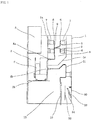
- FIG. 1 is a cross-sectional side view showing a switchgear according to Embodiment 1 of the present invention.
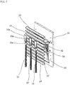
- FIG. 2 is a perspective view showing the rear surface side in the switchgear according to Embodiment 1 of the present invention.
- a circuit breaker compartment 3 in which a drawing type circuit breaker 2 is contained, is arranged in an upper stage of the front side (the left in the drawing) of a housing 1, the circuit breaker compartment 3 being defined by a grounding metallic partition wall 1a and a partition wall 1b.
- the circuit breaker 2 is drawable from the front side of the switchgear.
- An upper stage side disconnecting unit 4a and a lower stage side disconnecting unit 4b of a main circuit vertically spaced with a predetermined interval are provided in a fixed condition to a rear wall of the circuit breaker compartment 3 so as to be attachable/detachable to/from a connection terminal (not shown in the drawing) protrudingto the rear surface (the right in the drawing) of the circuit breaker 2.
- the upper side of the circuit breaker compartment 3 serves as a control device compartment 5 in which control devices (not shown in the drawing) are contained.
- the upper side of the back surface side of the circuit breaker compartment 3 is defined by the grounding metallic partition wall 1a and a partition wall 1c and serves as a busbar compartment 8 in which three phase busbars 6 supported by insulators 7 and branch conductors 9 placed corresponding to the busbars 6 are disposed.
- the upper stage side disconnecting unit 4a connected on the upper stage side of the circuit breaker 2 is connected to the busbar 6 by the branch conductor 9 to be contained in the busbar compartment 8.
- the rear side and the lower side of the busbar compartment 8 serve as a cable compartment 12 in which a cable 10 of the down stream side and a down stream side conductor 11 are contained.
- One end portion 10a of the cable 10 is connected to the down stream side conductor 11 to be connected via the down stream side conductor 11 to the lower stage side disconnecting unit 4b connected to the lower stage side of the circuit breaker 2; and the other end is connected to an external cable (not shown in the drawing).
- An air intake portion 30 that performs an air intake from the outside of the switchgear is provided on the housing 1, for example, on a lower rear wall (the lower rear surface wall side of the switchgear) of the cable compartment 12.
- An air intake mechanism attachment body 31 is arranged on the air intake portion 30 provided on the housing 1; and an air intake opening 32 composed of a plurality of slit-shaped wind windows is provided in the air intake mechanism attachment body 31.
- a check valve type shutter 33 which is faced to the air intake opening 32 to perform an air intake from the outside of the housing 1 and to block the air intake opening 32 in the occurrence of an internal short circuit fault, is arranged on the inner side of the air intake opening 32 on the housing 1.
- An opening position which is for performing the air intake of the check valve type shutter 33 is maintained by an air intake position support body 34.
- a ground fault partition body 35 is arranged between the check valve type shutter 33 and, for example, the cable 10 connected to the down stream side conductor 11 that is a conductive portion in the housing 1.
- FIG. 2 is a perspective view showing the rear surface side in the switchgear of FIG. 1 . It is desirable to use a material made of a conductive metal plate for the ground fault partition body 35 so that a strayed arc easily causes a ground fault. When an arc generated on the down stream side conductor 11 strays and comes close to the check valve type shutter 33, the arc causes the ground fault not via the check valve type shutter 33 but via the ground fault partition body 35; and therefore, the generation of the force 22 of the opening direction of the shutter shown by FIG. 5 and FIG. 6 can be prevented.
- An opening portion 36 is provided in the ground fault partition body 35 so as not to cause a delay in the close operation of the check valve type shutter 33, the delay being due to that fluid resistance generated by the ground fault partition body 35 gives an influence on high pressure propagation during the internal short circuit fault.
- the ground fault partition body 35 is formed with the opening portion 36 having a size in which the strayed arc causes the ground fault via the ground fault partition body 35.
- the internal configuration of the switchgear shown in FIG. 1 represents an example and is not limited to the arrangement configuration of the drawing.
- FIG. 1 there is shown a case where the air intake portion 30 is provided on the lower rear wall (the lower rear surface wall side of the switchgear) of the cable compartment 12, but not limited to this.
- the air intake portion 30 is provided on the lower left front surface side (the lower front side of the switchgear) of the cable compartment 12 in FIG. 1 , or on the lower lateral side (the lower lateral side of the switchgear) of the cable compartment 12 in FIG. 1 , or on a floor portion of the switchgear, or a configuration other that is also permissible.
- Each case represents the switchgear which is provided with the ground fault partition body 35 which is for suppressing the influence of the arc on the check valve type shutter 33 with respect to the switchgear equipped with a mechanism which comprises: the normal air intake portion 30 for ventilation; and the check valve type shutter 33 that faces a place where the high temperature and high pressure gas is flown back in the air intake portion 30 during the internal short circuit fault to be discharged to the outside of the switchgear.
- the strayed arc causes the ground fault not via the check valve type shutter 33 but via the ground fault partition body 35 in the switchgear which comprises: the air intake opening 32 provided on the front surface, the rear surface, or the like of the switchgear; and the check valve type shutter 33 that blocks the air intake opening 32 during the internal short circuit fault. Therefore, since the arc does not go through the check valve type shutter 33, there does not occur a phenomenon in which the check valve type shutter 33 is opened, reliability of the operation of the check valve type shutter 33 is remarkably improved and the switchgear can be made compact as compared to the aforementioned Patent Document 1 and Patent Document 2.
- FIG. 3 is a perspective view showing the rear surface side in a switchgear according to Embodiment 2 of the present invention.
- FIG. 3 represents a structure according to Embodiment 2 of the present invention, in which a ground fault frame body 37 is arranged between a check valve type shutter 33 and, for example, a cable 10 connected to a down stream side conductor 11 that is a conductive portion in a housing 1, in place of the ground fault partition body 35 shown in FIG. 2 .
- the ground fault frame bodies 37 are extended in a vertical direction and are each arranged in a direction perpendicular to the cable 10 connected to the down stream side conductor 11.
- the ground fault frame bodies 37 are provided in the vertical direction in plural numbers.
- the plurality of these ground fault frame bodies 37 are arranged at such an interval that a strayed arc goes therethrough to cause a ground fault.
- ground fault frame bodies 37 are each configured in a streamlined shape that reduces flow velocity resistance against propagation of high temperature and high pressure gas during an internal short circuit fault as shown in FIG. 3 ; and thus, fluid resistance generated by arranging the ground fault frame bodies 37 is reduced and the strayed arc causes the ground fault not via the check valve type shutter 33 but via the ground fault frame body 37.
- FIG. 4 is a perspective view showing the rear surface side in a switchgear according to Embodiment 3 of the present invention.
- FIG. 4 represents a structure according to Embodiment 3 of the present invention, in which a ground fault frame body 38 is arranged between a check valve type shutter 33 and, for example, a cable 10 connected to a down stream side conductor 11 that is a conductive portion in the inside of a housing 1, in place of the ground fault frame body 37 shown in FIG. 3 .
- the ground fault frame body 38 is extended in a vertical direction and is arranged in a direction parallel to the cable 10 connected to the down stream side conductor 11.
- the ground fault frame bodies 38 are provided in a horizontal direction in plural numbers.
- the plurality of these ground fault frame bodies 38 are arranged at such an interval that a strayed arc goes therethrough to cause a ground fault.
- ground fault frame bodies 38 are each configured in a streamlined shape that reduces flow velocity resistance against propagation of high temperature and high pressure gas during an internal short circuit fault as shown in FIG. 4 ; and thus, fluid resistance generated by arranging the ground fault frame bodies 38 is reduced and the strayed arc causes the ground fault not via the check valve type shutter 33 but via the ground fault frame body 38.
- the ground fault frame body 38 is arranged in the direction parallel to, for example, the cable 10 connected to the down stream side conductor 11 that is the conductive portion in the inside of the housing 1; and thus, the ground fault is likely to be caused and therefore the interval between the ground fault frame bodies 38 can be elongated and an improvement in reliability of the operation of the check valve type shutter 33 can be inexpensively actualized.
- the present invention can freely combine the respective embodiments and appropriately modify and/or omit the respective embodiments, within the scope of the present invention.
- the present invention is suitable for actualizing a switchgear which improves reliability of the operation of a check valve type shutter and can achieve compactification.
Landscapes
- Engineering & Computer Science (AREA)
- Power Engineering (AREA)
- Patch Boards (AREA)
Applications Claiming Priority (2)
| Application Number | Priority Date | Filing Date | Title |
|---|---|---|---|
| JP2014193328 | 2014-09-24 | ||
| PCT/JP2015/075041 WO2016047411A1 (ja) | 2014-09-24 | 2015-09-03 | スイッチギヤ |
Publications (3)
| Publication Number | Publication Date |
|---|---|
| EP3200295A1 true EP3200295A1 (de) | 2017-08-02 |
| EP3200295A4 EP3200295A4 (de) | 2018-04-25 |
| EP3200295B1 EP3200295B1 (de) | 2023-08-30 |
Family
ID=55580939
Family Applications (1)
| Application Number | Title | Priority Date | Filing Date |
|---|---|---|---|
| EP15843515.6A Active EP3200295B1 (de) | 2014-09-24 | 2015-09-03 | Schaltanlage |
Country Status (6)
| Country | Link |
|---|---|
| US (1) | US10164411B2 (de) |
| EP (1) | EP3200295B1 (de) |
| JP (1) | JP5944083B1 (de) |
| KR (1) | KR101893670B1 (de) |
| CN (1) | CN106797110B (de) |
| WO (1) | WO2016047411A1 (de) |
Families Citing this family (2)
| Publication number | Priority date | Publication date | Assignee | Title |
|---|---|---|---|---|
| WO2020083505A1 (en) * | 2018-10-26 | 2020-04-30 | Abb Schweiz Ag | Switchgear comprising a passive arc protection |
| JP7717523B2 (ja) * | 2021-07-30 | 2025-08-04 | 株式会社東芝 | スイッチギヤ |
Family Cites Families (27)
| Publication number | Priority date | Publication date | Assignee | Title |
|---|---|---|---|---|
| JPS552372B2 (de) | 1972-08-15 | 1980-01-19 | ||
| JPS536442B2 (de) | 1973-06-20 | 1978-03-08 | ||
| JPS56120040A (en) | 1980-02-26 | 1981-09-21 | Mitsubishi Electric Corp | Switch |
| SE430738B (sv) * | 1982-05-06 | 1983-12-05 | Asea Ab | Anordning vid en ventilationsoppning for en kapslad elektrisk kopplingsutrustning |
| JPH0574112U (ja) * | 1992-03-03 | 1993-10-08 | 日新電機株式会社 | ガス絶縁スイッチギヤ |
| US5710402A (en) * | 1996-07-30 | 1998-01-20 | Abb Power T&D Company Inc. | Arc-resistant switchgear enclosure employing a toggle flap venting system |
| US5861596A (en) * | 1997-04-01 | 1999-01-19 | Eaton Corporation | Dual baffle apparatus for electrical switching device |
| US6144001A (en) * | 1997-06-30 | 2000-11-07 | Siemens Energy & Automation, Inc. | Circuit breaker terminal shield with integral securing and installation and removal features apparatus, means and system |
| US6205017B1 (en) * | 2000-01-21 | 2001-03-20 | Eaton Corporation | Switchgear assembly with front accessible slide-in fixed power switch |
| WO2008136113A1 (ja) * | 2007-04-26 | 2008-11-13 | Mitsubishi Electric Corporation | 金属閉鎖形スイッチギヤ |
| KR101111012B1 (ko) | 2007-06-25 | 2012-02-13 | 미쓰비시덴키 가부시키가이샤 | 금속폐쇄형 스위치기어 |
| JP5017003B2 (ja) * | 2007-07-09 | 2012-09-05 | 株式会社東芝 | 金属閉鎖形スイッチギヤ |
| US7576985B2 (en) * | 2007-12-03 | 2009-08-18 | Rockwell Automation Technologies, Inc. | Rapid cooling of exhaust from arc resistant electrical equipment |
| US7974078B2 (en) * | 2008-01-23 | 2011-07-05 | Eaton Corporation | Electrical enclosure assembly having venting system |
| US8242395B2 (en) * | 2008-02-21 | 2012-08-14 | Siemens Industry, Inc. | Circuit breaker compartment arc flash venting system |
| US8325467B2 (en) * | 2009-12-17 | 2012-12-04 | Eaton Corporation | Method and apparatus to reduce internal pressure caused by an arcing fault in an electrical enclosure |
| US7952857B1 (en) * | 2010-02-22 | 2011-05-31 | Motley Gregory O | Arc-resistant switchgear enclosure with ambient air ventilation system |
| US9609769B2 (en) * | 2010-07-29 | 2017-03-28 | Rockwell Automation Technologies, Inc. | System and method for ventilating and isolating electrical equipment |
| KR101248608B1 (ko) * | 2011-08-31 | 2013-03-28 | 현대중공업 주식회사 | 차단부 인출식 큐비클형 가스절연 개폐장치 |
| KR101173034B1 (ko) * | 2011-11-01 | 2012-08-10 | 대진전기 (주) | 고압전력용 일체형 수배전반 |
| JP5837093B2 (ja) * | 2011-12-27 | 2015-12-24 | 三菱電機株式会社 | 電気室 |
| JP5921269B2 (ja) * | 2012-03-14 | 2016-05-24 | 株式会社日立製作所 | スイッチギヤ |
| DE102012210279B3 (de) * | 2012-06-19 | 2013-09-05 | Siemens Aktiengesellschaft | Verschlussvorrichtung für eine Schaltanlage |
| CN103794988B (zh) * | 2012-10-26 | 2017-07-28 | 施耐德电器工业公司 | 送气组件 |
| US8785770B2 (en) * | 2012-11-14 | 2014-07-22 | Central Electric Company | Arc-resistant switchgear enclosure with vent arrangement of a lower compartment |
| US9627866B2 (en) * | 2014-07-31 | 2017-04-18 | Abb Schweiz Ag | Door mounted vent flap structure for arc-resistant compartment |
| KR101636343B1 (ko) | 2015-12-07 | 2016-07-05 | 주식회사 광명전기 | 금속폐쇄형 스위치기어 |
-
2015
- 2015-09-03 WO PCT/JP2015/075041 patent/WO2016047411A1/ja not_active Ceased
- 2015-09-03 EP EP15843515.6A patent/EP3200295B1/de active Active
- 2015-09-03 JP JP2016506929A patent/JP5944083B1/ja active Active
- 2015-09-03 KR KR1020167035576A patent/KR101893670B1/ko active Active
- 2015-09-03 US US15/307,244 patent/US10164411B2/en active Active
- 2015-09-03 CN CN201580050249.6A patent/CN106797110B/zh not_active Expired - Fee Related
Also Published As
| Publication number | Publication date |
|---|---|
| US10164411B2 (en) | 2018-12-25 |
| CN106797110B (zh) | 2019-02-01 |
| JP5944083B1 (ja) | 2016-07-05 |
| US20170054278A1 (en) | 2017-02-23 |
| EP3200295A4 (de) | 2018-04-25 |
| KR20170004010A (ko) | 2017-01-10 |
| CN106797110A (zh) | 2017-05-31 |
| KR101893670B1 (ko) | 2018-08-30 |
| WO2016047411A1 (ja) | 2016-03-31 |
| JPWO2016047411A1 (ja) | 2017-04-27 |
| EP3200295B1 (de) | 2023-08-30 |
Similar Documents
| Publication | Publication Date | Title |
|---|---|---|
| CN101636889B (zh) | 金属封闭形开关装置 | |
| JP5274608B2 (ja) | スイッチギヤ | |
| US9117607B2 (en) | Muffler for enhanced arc protection | |
| JP6143990B1 (ja) | ガス絶縁開閉装置 | |
| US20100258532A1 (en) | Arc resistant switchgear vertical exhaust system | |
| JP4988833B2 (ja) | 金属閉鎖形スイッチギヤ | |
| JP2009017774A (ja) | 三相交流電動機のソフトスタートまたはソフトストップを制御するための装置、いわゆるソフトスタータ | |
| CN104934265A (zh) | 用于断路器的模块化气体排放组件 | |
| US10164411B2 (en) | Switchgear | |
| JP5889256B2 (ja) | 配電盤 | |
| WO2012169082A1 (ja) | スイッチギヤ | |
| CN105051853A (zh) | 用于中压开关设备组件的气体冷却器 | |
| CN106415958B (zh) | 开关机构 | |
| JP6466033B2 (ja) | スイッチギヤ | |
| US20120097642A1 (en) | Self-pressurized arc diverter | |
| CN206323059U (zh) | 一种用于充气柜内引导电弧方向的母线连接结构 | |
| JP3203676U (ja) | ガス絶縁スイッチギヤ | |
| JP6190442B2 (ja) | ガス絶縁スイッチギヤ | |
| KR20130102313A (ko) | 가스절연 개폐장치 | |
| JP5992320B2 (ja) | スイッチギヤ | |
| CN111868871B (zh) | 保护继电装置及电力转换系统 | |
| CN202872214U (zh) | 一种一体式配电箱 | |
| JP2021083175A (ja) | 母線の配置構造、閉鎖配電盤 | |
| WO2018212210A1 (ja) | 遮断器及びスイッチギヤ | |
| HK1139513B (en) | Metal closed type switch gear |
Legal Events
| Date | Code | Title | Description |
|---|---|---|---|
| STAA | Information on the status of an ep patent application or granted ep patent |
Free format text: STATUS: THE INTERNATIONAL PUBLICATION HAS BEEN MADE |
|
| PUAI | Public reference made under article 153(3) epc to a published international application that has entered the european phase |
Free format text: ORIGINAL CODE: 0009012 |
|
| STAA | Information on the status of an ep patent application or granted ep patent |
Free format text: STATUS: REQUEST FOR EXAMINATION WAS MADE |
|
| 17P | Request for examination filed |
Effective date: 20170220 |
|
| AK | Designated contracting states |
Kind code of ref document: A1 Designated state(s): AL AT BE BG CH CY CZ DE DK EE ES FI FR GB GR HR HU IE IS IT LI LT LU LV MC MK MT NL NO PL PT RO RS SE SI SK SM TR |
|
| AX | Request for extension of the european patent |
Extension state: BA ME |
|
| DAV | Request for validation of the european patent (deleted) | ||
| DAX | Request for extension of the european patent (deleted) | ||
| A4 | Supplementary search report drawn up and despatched |
Effective date: 20180322 |
|
| RIC1 | Information provided on ipc code assigned before grant |
Ipc: H02B 1/56 20060101AFI20180316BHEP Ipc: H02B 11/24 20060101ALN20180316BHEP Ipc: H02B 13/025 20060101ALI20180316BHEP |
|
| STAA | Information on the status of an ep patent application or granted ep patent |
Free format text: STATUS: EXAMINATION IS IN PROGRESS |
|
| 17Q | First examination report despatched |
Effective date: 20200318 |
|
| REG | Reference to a national code |
Ref country code: DE Ref legal event code: R079 Ref document number: 602015085457 Country of ref document: DE Free format text: PREVIOUS MAIN CLASS: H02B0001280000 Ipc: H02B0001560000 Ref country code: DE Ref legal event code: R079 Free format text: PREVIOUS MAIN CLASS: H02B0001280000 Ipc: H02B0001560000 |
|
| GRAP | Despatch of communication of intention to grant a patent |
Free format text: ORIGINAL CODE: EPIDOSNIGR1 |
|
| STAA | Information on the status of an ep patent application or granted ep patent |
Free format text: STATUS: GRANT OF PATENT IS INTENDED |
|
| RIC1 | Information provided on ipc code assigned before grant |
Ipc: H02B 11/24 20060101ALN20230221BHEP Ipc: H02B 13/025 20060101ALI20230221BHEP Ipc: H02B 1/56 20060101AFI20230221BHEP |
|
| INTG | Intention to grant announced |
Effective date: 20230310 |
|
| P01 | Opt-out of the competence of the unified patent court (upc) registered |
Effective date: 20230601 |
|
| GRAS | Grant fee paid |
Free format text: ORIGINAL CODE: EPIDOSNIGR3 |
|
| GRAA | (expected) grant |
Free format text: ORIGINAL CODE: 0009210 |
|
| STAA | Information on the status of an ep patent application or granted ep patent |
Free format text: STATUS: THE PATENT HAS BEEN GRANTED |
|
| AK | Designated contracting states |
Kind code of ref document: B1 Designated state(s): AL AT BE BG CH CY CZ DE DK EE ES FI FR GB GR HR HU IE IS IT LI LT LU LV MC MK MT NL NO PL PT RO RS SE SI SK SM TR |
|
| REG | Reference to a national code |
Ref country code: GB Ref legal event code: FG4D |
|
| REG | Reference to a national code |
Ref country code: CH Ref legal event code: EP |
|
| REG | Reference to a national code |
Ref country code: DE Ref legal event code: R096 Ref document number: 602015085457 Country of ref document: DE |
|
| REG | Reference to a national code |
Ref country code: IE Ref legal event code: FG4D |
|
| REG | Reference to a national code |
Ref country code: LT Ref legal event code: MG9D |
|
| REG | Reference to a national code |
Ref country code: NL Ref legal event code: MP Effective date: 20230830 |
|
| REG | Reference to a national code |
Ref country code: AT Ref legal event code: MK05 Ref document number: 1606671 Country of ref document: AT Kind code of ref document: T Effective date: 20230830 |
|
| PG25 | Lapsed in a contracting state [announced via postgrant information from national office to epo] |
Ref country code: GR Free format text: LAPSE BECAUSE OF FAILURE TO SUBMIT A TRANSLATION OF THE DESCRIPTION OR TO PAY THE FEE WITHIN THE PRESCRIBED TIME-LIMIT Effective date: 20231201 |
|
| PG25 | Lapsed in a contracting state [announced via postgrant information from national office to epo] |
Ref country code: IS Free format text: LAPSE BECAUSE OF FAILURE TO SUBMIT A TRANSLATION OF THE DESCRIPTION OR TO PAY THE FEE WITHIN THE PRESCRIBED TIME-LIMIT Effective date: 20231230 |
|
| PG25 | Lapsed in a contracting state [announced via postgrant information from national office to epo] |
Ref country code: SE Free format text: LAPSE BECAUSE OF FAILURE TO SUBMIT A TRANSLATION OF THE DESCRIPTION OR TO PAY THE FEE WITHIN THE PRESCRIBED TIME-LIMIT Effective date: 20230830 Ref country code: RS Free format text: LAPSE BECAUSE OF FAILURE TO SUBMIT A TRANSLATION OF THE DESCRIPTION OR TO PAY THE FEE WITHIN THE PRESCRIBED TIME-LIMIT Effective date: 20230830 Ref country code: NO Free format text: LAPSE BECAUSE OF FAILURE TO SUBMIT A TRANSLATION OF THE DESCRIPTION OR TO PAY THE FEE WITHIN THE PRESCRIBED TIME-LIMIT Effective date: 20231130 Ref country code: LV Free format text: LAPSE BECAUSE OF FAILURE TO SUBMIT A TRANSLATION OF THE DESCRIPTION OR TO PAY THE FEE WITHIN THE PRESCRIBED TIME-LIMIT Effective date: 20230830 Ref country code: LT Free format text: LAPSE BECAUSE OF FAILURE TO SUBMIT A TRANSLATION OF THE DESCRIPTION OR TO PAY THE FEE WITHIN THE PRESCRIBED TIME-LIMIT Effective date: 20230830 Ref country code: IS Free format text: LAPSE BECAUSE OF FAILURE TO SUBMIT A TRANSLATION OF THE DESCRIPTION OR TO PAY THE FEE WITHIN THE PRESCRIBED TIME-LIMIT Effective date: 20231230 Ref country code: HR Free format text: LAPSE BECAUSE OF FAILURE TO SUBMIT A TRANSLATION OF THE DESCRIPTION OR TO PAY THE FEE WITHIN THE PRESCRIBED TIME-LIMIT Effective date: 20230830 Ref country code: GR Free format text: LAPSE BECAUSE OF FAILURE TO SUBMIT A TRANSLATION OF THE DESCRIPTION OR TO PAY THE FEE WITHIN THE PRESCRIBED TIME-LIMIT Effective date: 20231201 Ref country code: FI Free format text: LAPSE BECAUSE OF FAILURE TO SUBMIT A TRANSLATION OF THE DESCRIPTION OR TO PAY THE FEE WITHIN THE PRESCRIBED TIME-LIMIT Effective date: 20230830 Ref country code: AT Free format text: LAPSE BECAUSE OF FAILURE TO SUBMIT A TRANSLATION OF THE DESCRIPTION OR TO PAY THE FEE WITHIN THE PRESCRIBED TIME-LIMIT Effective date: 20230830 |
|
| PG25 | Lapsed in a contracting state [announced via postgrant information from national office to epo] |
Ref country code: PL Free format text: LAPSE BECAUSE OF FAILURE TO SUBMIT A TRANSLATION OF THE DESCRIPTION OR TO PAY THE FEE WITHIN THE PRESCRIBED TIME-LIMIT Effective date: 20230830 Ref country code: NL Free format text: LAPSE BECAUSE OF FAILURE TO SUBMIT A TRANSLATION OF THE DESCRIPTION OR TO PAY THE FEE WITHIN THE PRESCRIBED TIME-LIMIT Effective date: 20230830 |
|
| PG25 | Lapsed in a contracting state [announced via postgrant information from national office to epo] |
Ref country code: ES Free format text: LAPSE BECAUSE OF FAILURE TO SUBMIT A TRANSLATION OF THE DESCRIPTION OR TO PAY THE FEE WITHIN THE PRESCRIBED TIME-LIMIT Effective date: 20230830 |
|
| PG25 | Lapsed in a contracting state [announced via postgrant information from national office to epo] |
Ref country code: SM Free format text: LAPSE BECAUSE OF FAILURE TO SUBMIT A TRANSLATION OF THE DESCRIPTION OR TO PAY THE FEE WITHIN THE PRESCRIBED TIME-LIMIT Effective date: 20230830 Ref country code: RO Free format text: LAPSE BECAUSE OF FAILURE TO SUBMIT A TRANSLATION OF THE DESCRIPTION OR TO PAY THE FEE WITHIN THE PRESCRIBED TIME-LIMIT Effective date: 20230830 Ref country code: ES Free format text: LAPSE BECAUSE OF FAILURE TO SUBMIT A TRANSLATION OF THE DESCRIPTION OR TO PAY THE FEE WITHIN THE PRESCRIBED TIME-LIMIT Effective date: 20230830 Ref country code: EE Free format text: LAPSE BECAUSE OF FAILURE TO SUBMIT A TRANSLATION OF THE DESCRIPTION OR TO PAY THE FEE WITHIN THE PRESCRIBED TIME-LIMIT Effective date: 20230830 Ref country code: DK Free format text: LAPSE BECAUSE OF FAILURE TO SUBMIT A TRANSLATION OF THE DESCRIPTION OR TO PAY THE FEE WITHIN THE PRESCRIBED TIME-LIMIT Effective date: 20230830 Ref country code: CZ Free format text: LAPSE BECAUSE OF FAILURE TO SUBMIT A TRANSLATION OF THE DESCRIPTION OR TO PAY THE FEE WITHIN THE PRESCRIBED TIME-LIMIT Effective date: 20230830 Ref country code: SK Free format text: LAPSE BECAUSE OF FAILURE TO SUBMIT A TRANSLATION OF THE DESCRIPTION OR TO PAY THE FEE WITHIN THE PRESCRIBED TIME-LIMIT Effective date: 20230830 Ref country code: PT Free format text: LAPSE BECAUSE OF FAILURE TO SUBMIT A TRANSLATION OF THE DESCRIPTION OR TO PAY THE FEE WITHIN THE PRESCRIBED TIME-LIMIT Effective date: 20240102 |
|
| REG | Reference to a national code |
Ref country code: CH Ref legal event code: PL |
|
| PG25 | Lapsed in a contracting state [announced via postgrant information from national office to epo] |
Ref country code: LU Free format text: LAPSE BECAUSE OF NON-PAYMENT OF DUE FEES Effective date: 20230903 |
|
| REG | Reference to a national code |
Ref country code: BE Ref legal event code: MM Effective date: 20230930 |
|
| PG25 | Lapsed in a contracting state [announced via postgrant information from national office to epo] |
Ref country code: LU Free format text: LAPSE BECAUSE OF NON-PAYMENT OF DUE FEES Effective date: 20230903 Ref country code: IT Free format text: LAPSE BECAUSE OF FAILURE TO SUBMIT A TRANSLATION OF THE DESCRIPTION OR TO PAY THE FEE WITHIN THE PRESCRIBED TIME-LIMIT Effective date: 20230830 Ref country code: MC Free format text: LAPSE BECAUSE OF FAILURE TO SUBMIT A TRANSLATION OF THE DESCRIPTION OR TO PAY THE FEE WITHIN THE PRESCRIBED TIME-LIMIT Effective date: 20230830 |
|
| REG | Reference to a national code |
Ref country code: DE Ref legal event code: R097 Ref document number: 602015085457 Country of ref document: DE |
|
| REG | Reference to a national code |
Ref country code: IE Ref legal event code: MM4A |
|
| PG25 | Lapsed in a contracting state [announced via postgrant information from national office to epo] |
Ref country code: IE Free format text: LAPSE BECAUSE OF NON-PAYMENT OF DUE FEES Effective date: 20230903 |
|
| PLBE | No opposition filed within time limit |
Free format text: ORIGINAL CODE: 0009261 |
|
| STAA | Information on the status of an ep patent application or granted ep patent |
Free format text: STATUS: NO OPPOSITION FILED WITHIN TIME LIMIT |
|
| PG25 | Lapsed in a contracting state [announced via postgrant information from national office to epo] |
Ref country code: CH Free format text: LAPSE BECAUSE OF NON-PAYMENT OF DUE FEES Effective date: 20230930 |
|
| GBPC | Gb: european patent ceased through non-payment of renewal fee |
Effective date: 20231130 |
|
| PG25 | Lapsed in a contracting state [announced via postgrant information from national office to epo] |
Ref country code: IE Free format text: LAPSE BECAUSE OF NON-PAYMENT OF DUE FEES Effective date: 20230903 Ref country code: FR Free format text: LAPSE BECAUSE OF NON-PAYMENT OF DUE FEES Effective date: 20231030 Ref country code: CH Free format text: LAPSE BECAUSE OF NON-PAYMENT OF DUE FEES Effective date: 20230930 Ref country code: SI Free format text: LAPSE BECAUSE OF FAILURE TO SUBMIT A TRANSLATION OF THE DESCRIPTION OR TO PAY THE FEE WITHIN THE PRESCRIBED TIME-LIMIT Effective date: 20230830 |
|
| 26N | No opposition filed |
Effective date: 20240603 |
|
| PG25 | Lapsed in a contracting state [announced via postgrant information from national office to epo] |
Ref country code: BE Free format text: LAPSE BECAUSE OF NON-PAYMENT OF DUE FEES Effective date: 20230930 |
|
| PG25 | Lapsed in a contracting state [announced via postgrant information from national office to epo] |
Ref country code: GB Free format text: LAPSE BECAUSE OF NON-PAYMENT OF DUE FEES Effective date: 20231130 |
|
| PG25 | Lapsed in a contracting state [announced via postgrant information from national office to epo] |
Ref country code: GB Free format text: LAPSE BECAUSE OF NON-PAYMENT OF DUE FEES Effective date: 20231130 |
|
| PG25 | Lapsed in a contracting state [announced via postgrant information from national office to epo] |
Ref country code: BG Free format text: LAPSE BECAUSE OF FAILURE TO SUBMIT A TRANSLATION OF THE DESCRIPTION OR TO PAY THE FEE WITHIN THE PRESCRIBED TIME-LIMIT Effective date: 20230830 |
|
| PG25 | Lapsed in a contracting state [announced via postgrant information from national office to epo] |
Ref country code: BG Free format text: LAPSE BECAUSE OF FAILURE TO SUBMIT A TRANSLATION OF THE DESCRIPTION OR TO PAY THE FEE WITHIN THE PRESCRIBED TIME-LIMIT Effective date: 20230830 |
|
| PG25 | Lapsed in a contracting state [announced via postgrant information from national office to epo] |
Ref country code: CY Free format text: LAPSE BECAUSE OF FAILURE TO SUBMIT A TRANSLATION OF THE DESCRIPTION OR TO PAY THE FEE WITHIN THE PRESCRIBED TIME-LIMIT; INVALID AB INITIO Effective date: 20150903 |
|
| PG25 | Lapsed in a contracting state [announced via postgrant information from national office to epo] |
Ref country code: HU Free format text: LAPSE BECAUSE OF FAILURE TO SUBMIT A TRANSLATION OF THE DESCRIPTION OR TO PAY THE FEE WITHIN THE PRESCRIBED TIME-LIMIT; INVALID AB INITIO Effective date: 20150903 |
|
| PGFP | Annual fee paid to national office [announced via postgrant information from national office to epo] |
Ref country code: DE Payment date: 20250730 Year of fee payment: 11 |
|
| PG25 | Lapsed in a contracting state [announced via postgrant information from national office to epo] |
Ref country code: TR Free format text: LAPSE BECAUSE OF FAILURE TO SUBMIT A TRANSLATION OF THE DESCRIPTION OR TO PAY THE FEE WITHIN THE PRESCRIBED TIME-LIMIT Effective date: 20230830 |