EP3200310B1 - Elektrisches speichersystem, steuerungsvorrichtung und steuerungsverfahren - Google Patents
Elektrisches speichersystem, steuerungsvorrichtung und steuerungsverfahren Download PDFInfo
- Publication number
- EP3200310B1 EP3200310B1 EP15844310.1A EP15844310A EP3200310B1 EP 3200310 B1 EP3200310 B1 EP 3200310B1 EP 15844310 A EP15844310 A EP 15844310A EP 3200310 B1 EP3200310 B1 EP 3200310B1
- Authority
- EP
- European Patent Office
- Prior art keywords
- battery
- charge
- discharge
- storage battery
- modules
- Prior art date
- Legal status (The legal status is an assumption and is not a legal conclusion. Google has not performed a legal analysis and makes no representation as to the accuracy of the status listed.)
- Not-in-force
Links
Images


Classifications
-
- H—ELECTRICITY
- H02—GENERATION; CONVERSION OR DISTRIBUTION OF ELECTRIC POWER
- H02J—ELECTRIC POWER NETWORKS; CIRCUIT ARRANGEMENTS OR SYSTEMS FOR SUPPLYING OR DISTRIBUTING ELECTRIC POWER; SYSTEMS FOR STORING ELECTRIC ENERGY
- H02J7/00—Circuit arrangements for charging or discharging batteries or for supplying loads from batteries
- H02J7/50—Circuit arrangements for charging or discharging batteries or for supplying loads from batteries acting upon multiple batteries simultaneously or sequentially
-
- B—PERFORMING OPERATIONS; TRANSPORTING
- B60—VEHICLES IN GENERAL
- B60L—PROPULSION OF ELECTRICALLY-PROPELLED VEHICLES; SUPPLYING ELECTRIC POWER FOR AUXILIARY EQUIPMENT OF ELECTRICALLY-PROPELLED VEHICLES; ELECTRODYNAMIC BRAKE SYSTEMS FOR VEHICLES IN GENERAL; MAGNETIC SUSPENSION OR LEVITATION FOR VEHICLES; MONITORING OPERATING VARIABLES OF ELECTRICALLY-PROPELLED VEHICLES; ELECTRIC SAFETY DEVICES FOR ELECTRICALLY-PROPELLED VEHICLES
- B60L58/00—Methods or circuit arrangements for monitoring or controlling batteries or fuel cells, specially adapted for electric vehicles
- B60L58/10—Methods or circuit arrangements for monitoring or controlling batteries or fuel cells, specially adapted for electric vehicles for monitoring or controlling batteries
-
- Y—GENERAL TAGGING OF NEW TECHNOLOGICAL DEVELOPMENTS; GENERAL TAGGING OF CROSS-SECTIONAL TECHNOLOGIES SPANNING OVER SEVERAL SECTIONS OF THE IPC; TECHNICAL SUBJECTS COVERED BY FORMER USPC CROSS-REFERENCE ART COLLECTIONS [XRACs] AND DIGESTS
- Y02—TECHNOLOGIES OR APPLICATIONS FOR MITIGATION OR ADAPTATION AGAINST CLIMATE CHANGE
- Y02T—CLIMATE CHANGE MITIGATION TECHNOLOGIES RELATED TO TRANSPORTATION
- Y02T10/00—Road transport of goods or passengers
- Y02T10/60—Other road transportation technologies with climate change mitigation effect
- Y02T10/70—Energy storage systems for electromobility, e.g. batteries
-
- Y—GENERAL TAGGING OF NEW TECHNOLOGICAL DEVELOPMENTS; GENERAL TAGGING OF CROSS-SECTIONAL TECHNOLOGIES SPANNING OVER SEVERAL SECTIONS OF THE IPC; TECHNICAL SUBJECTS COVERED BY FORMER USPC CROSS-REFERENCE ART COLLECTIONS [XRACs] AND DIGESTS
- Y02—TECHNOLOGIES OR APPLICATIONS FOR MITIGATION OR ADAPTATION AGAINST CLIMATE CHANGE
- Y02T—CLIMATE CHANGE MITIGATION TECHNOLOGIES RELATED TO TRANSPORTATION
- Y02T90/00—Enabling technologies or technologies with a potential or indirect contribution to GHG emissions mitigation
- Y02T90/10—Technologies relating to charging of electric vehicles
- Y02T90/16—Information or communication technologies improving the operation of electric vehicles
Definitions
- the present invention relates to an electricity storage system including a plurality of battery modules and to a control device and a control method used in the electricity storage system.
- each of the battery modules includes a plurality of battery cells and a battery control device, which collects the information of each battery cell.
- WO 2013/145000 A1 shows electricity storage systems which include a technique that controls the signals balancing the battery modules, charge/discharge voltages, and charge/discharge currents based on the information from the individual battery modules.
- WO 2014/059050 A1 discloses a system of replaceable and configurable battery power modules (BPMs) operatively connected to a smart management module (SMM) .
- BPM can include a plurality of battery cells (e.g., Lithium) wired together in series and/or parallel.
- the BPMS are independently capable of cell balancing, monitoring and recording critical information about cell performance.
- the BPMs, wired together in series and/or parallel are connected to the SM M to form a cumulative battery pack.
- the performance and control limit information from each BPM can be used by the SMM to properly control the charging and discharging of the complete battery pack.
- US 2014/0285022 A1 relates to an uninterrupted power supply system that incorporates a plurality of lithium batteries as a back-up power supply to an AC power supply.
- a power output switch is automatically activated by a power control system to draw power from a lithium battery pack.
- a battery pack is monitored by a battery management system that is coupled to battery monitoring modules couple to each battery.
- the battery management system may be configured to monitor the voltage and/or temperature of each battery.
- an uninterrupted power supply system comprises a battery unit balancing system that maintains each battery within a battery unit below a threshold voltage value.
- a charging circuit and discharging circuit is used to maintain the batteries in a ready state of charge when not being used for the output power.
- conventional electricity storage systems fix the characteristics of the storage batteries, which serve as control targets, and are not optimized for controlling the storage batteries having the characteristics thereof.
- the characteristics as a whole storage battery may be changed depending on the connection form of the battery modules.
- the characteristics of the individual storage battery modules per se are different even in a case in which the connection form of the battery modules is the same, the characteristics as the whole storage battery are also changed. Therefore, it has been difficult for the electricity storage system, in which the characteristics of the storage battery serving as the control target are fixed, to control charge/discharge of the storage battery which is formed with the battery modules having different characteristics.
- An electricity storage system includes: a storage battery including one or more battery blocks (connected in parallel, wherein each battery block is formed with the two or more battery modules connected in series; a battery controller connected to each battery block (12a, 12b) via a respective communication line; and a charge/discharge controller connected to the storage battery via an electric power line.
- the battery controller includes a characteristic acquirer that acquires characteristic information representing a physical characteristic of each battery module from each of the plurality of battery modules, and a calculator that calculates a set value for controlling charge/discharge of the storage battery based on the characteristic information of the battery module acquired by the characteristic acquirer, battery configuration information representing a connection form of the plurality of battery modules constituting the storage battery and a fixed value representing the physical characteristic of each battery module.
- the battery configuration information is information including a parallel number representing the number of the communication lines and a series number representing the number of the battery modules connected to each communication line.
- the charge/discharge controller controls the charge/discharge of the storage battery based on the set value calculated by the calculator.
- the set value for controlling the charge/discharge of the storage battery can be dynamically calculated.
- Fig. 1 is a view schematically showing the entire configuration of an electricity storage system 1 according to the embodiment.
- the electricity storage system 1 includes: a storage battery 10, a charge/discharge controller 20, a battery controller 30, an operation panel 40, an electric power line 50, a first communication line 60a, and a second communication line 60b.
- the storage battery 10 includes a first battery block 12a and a second battery block 12b.
- first battery block 12a and the second battery block 12b are particularly distinguished from each other, they are simply collectively referred to as "battery blocks 12".
- Fig. 1 exemplarily shows a case in which the electricity storage system 1 includes two battery blocks 12.
- the number of the battery blocks 12 is not limited to 2, and it is only required to be formed with one or more battery blocks 12 connected in parallel. Therefore, the number of the battery blocks 12 included in the electricity storage system 1 may be 1, 3, or more.
- the first battery block 12a includes a first battery module 14a, a second battery module 14b, a third battery module 14c, and a fourth battery module 14d.
- the second battery block 12b includes a fifth battery module 14e, a sixth battery module 14f, a seventh battery module 14g, and an eighth battery module 14h.
- Fig. 1 exemplarily shows the case in which each of the first battery block 12a and the second battery block 12b includes four battery modules 14.
- the number of the battery modules 14 included in each battery block is not limited to 4.
- Each of the battery blocks 12 is only required to be formed with two or more battery modules 14 connected in series.
- the battery modules 14 are secondary batteries which can be repeatedly used by charging. Although it is not shown, the battery module 14 is formed, for example, by connecting a plurality of lithium-ion secondary batteries, which are called battery cells, in series and in parallel.
- the battery module 14 further includes a measure, which measures time-varying physical characteristics such as a current voltage, a charged or discharged current, SOC (State Of Charge; charge quantity), and a temperature of the battery module 14 and includes a transmitter/receiver for transmitting measured values to outside or receiving control signals from outside. This transmitter/receiver is further capable of transmitting time-invariable fixed values, which represent the physical characteristics of the battery module 14, to outside. Details about the fixed values representing the physical characteristics of the battery module 14 will be described later.
- the battery cells are not limited to lithium-ion secondary batteries, but may be other secondary batteries.
- the storage battery may be a nickel-hydrogen battery, a nickel-cadmium battery, or the like.
- the battery blocks 12 is an assembled battery formed with the plurality of battery modules 14 connected in series .
- the storage battery 10 is formed with one or a plurality of battery blocks 12 further connected in parallel.
- the number of the battery modules 14 provided in the battery block 12 will be described as “series number Ns”
- the number of the battery blocks 12 provided in the storage battery 10 will be described as "parallel number Np”.
- the storage battery 10 includes the plurality of battery blocks 12, in other words, if the parallel number Np is 2 or more, there is an assumption that the number of the battery modules 14 provided in each of the battery blocks 12 is the same. Therefore, the total number Nt of the battery modules 14 provided in the storage battery 10 is obtained by the product of the parallel number Np and the series number Ns. Furthermore, if the number of the battery block 12 provided in the storage battery 10 is 1, in other words, even if the plurality of battery blocks 12 are not connected in parallel, this case is described as "the parallel number Np is 1" for the sake of convenience.
- the charge/discharge controller 20 is connected via the storage battery 10 and the electric power line 50.
- the charge/discharge controller 20 controls charge/discharge of the storage battery 10.
- the charge/discharge controller 20 is formed with a circuit independent from the storage battery 10 and the battery controller 30 and functions as a charge/discharge controlling device of the storage battery 10.
- the charge/discharge controller 20 includes a bidirectional inverter.
- a direct-current terminal of the bidirectional inverter is electrically connected to the electric power line 50.
- An alternating-current terminal of the bidirectional inverter is electrically connected to a system power source 2 and a load (not shown) .
- the system power source 2 is an alternating-current power source supplied by an electric power company.
- the bidirectional inverter converts the direct-current power discharged by the storage battery 10 to alternating-current power and outputs that.
- the bidirectional inverter also converts the alternating-current power, which is from the system power source 2, to direct-current power and outputs that to the electric power line 50.
- the storage battery 10 is charged by the electric power of the system power source 2 converted to direct-current power by the bidirectional inverter for example during the night time.
- the electric power stored in the storage battery 10 is converted to alternating-current power by the bidirectional inverter, is supplied to the load, and is utilized as backup electric power in peak-cut of the system power source 2 or in the case of electricity outage of the system power source 2.
- the battery controller 30 is connected to each of the battery modules 14 of the first battery block 12a via the first communication line 60a.
- the battery controller 30 is also connected to each of the battery modules 14 of the second battery block 12b via a second communication line 60b.
- first communication line 60a and the second communication line 60b are particularly distinguished from each other, they will be simply described as "communication lines 60".
- the battery controller 30 connects each battery block 12 via each communication line 60. Therefore, the battery controller 30 includes a first connector 31a, a second connector 31b, and a third connector 31c.
- the first connector 31a functions as a first connecting terminal which connects to the first communication line 60a.
- the second connector 31b functions as a second connecting terminal which connects to the second communication line 60b.
- the third connector 31c is not connected to any of the communication lines 60.
- connectors 31 except for the case in which the first connector 31a, the second connector 31b, and the third connector 31c are particularly distinguished from one another, they will be simply described as "connectors 31".
- the number of the communication lines 60 matches the value of the parallel number Np. If the storage battery 10 includes three battery blocks 12 in the example shown in Fig. 1 , the third battery block 12 is connected to the battery controller 30 via the third communication line. This communication line is connected to the third connector 31c.
- the battery controller 30 calculates the set value for controlling charge/discharge of the storage battery 10 and outputs them to the charge/discharge controller 20.
- the battery controller 30 is formed with a circuit independent from the storage battery 10 and the charge/discharge controller 20 and functions as a control device which calculates the set value for the charge/discharge controller 20 to control the storage battery 10.
- the charge/discharge controller 20 controls charge/discharge of the storage battery 10 based on the calculated set value calculated by the battery controller 30.
- the operation panel 40 is provided on a surface of a chassis (not shown) of the electricity storage system 1.
- the operation panel 40 is connected to the battery controller 30.
- the operation panel 40 functions as a user interface for a user to input the information, which is used for calculating the set value for controlling the charge/discharge of the storage battery 10, to the battery controller 30.
- the operation panel 40 and the charge/discharge controller 20 may be connected to each other.
- the battery controller 30 acquires the information, which is used for calculating the set value for controlling the charge/discharge of the storage battery 10, from the charge/discharge controller 20.
- Fig. 2 is a diagram schematically showing a functional configuration of the battery controller 30 according to the embodiment.
- the battery controller 30 includes a connector 31, a characteristic acquirer 32, a calculator 33, a configuration information acquirer 34, and an output unit 35.
- Fig. 2 shows the functional configuration for the battery controller 30 according to the embodiment to realize calculations of the set value for controlling the charge/discharge of the storage battery 10, and other configurations are omitted.
- the elements described as functional blocks which carry out various processes can be formed by, in terms of hardware, a CPU (Central Processing Unit), a main memory, and other LSI (Large Scale Integration).
- the elements are realized by, for example, a program loaded to the main memory. Therefore, it is understood by those skilled in the art that these functional blocks can be realized in various forms by only hardware, only software, or combinations thereof, and the functional blocks are not limited to any one of them.
- the characteristic acquirer 32 acquires physical information, which represents physical characteristics of each of the battery modules 14, from each of the plurality of battery modules 14.
- the physical information, which represents physical characteristics of each of the battery modules 14 includes the measured values of the current physical characteristics of each of the battery modules 14 and the fixed values, which represent the physical characteristics of each of the battery modules 14.
- the "measured values of the current physical characteristics of the battery module 14" are information such as the current voltage, charged or discharged current, SOC, temperature, etc. of the battery module 14 measured by the above described measure.
- the "fixed values, which represent the physical characteristics of the battery module 14" are thresholds for charge/discharge control determined based on the physical characteristics of the battery module 14. Specific examples of the fixed values, which represent the physical characteristics of the battery module 14, include “charge/discharge-end threshold", “overvoltage warning threshold”, “overcurrent warning threshold”, and “excessive-temperature warning threshold”.
- the charge/discharge-end threshold includes a charge-stop threshold for preventing the battery module 14 from being overcharged and a discharge-stop threshold for preventing the battery module 14 from overdischarging.
- the chargeable maximum charge capacity of the battery module 14 is determined by the types and number of the battery cells constituting the battery module 14. Therefore, the charge-stop threshold is defined by using the SOC of the battery module 14 or the voltage of the battery module 14 at that point. Similarly, the discharge-stop threshold is also defined by using the SOC or voltage of the battery module 14.
- the charge/discharge-end threshold is defined by SOC
- the SOC of the battery module 14 exceeds the range which has the charge-stop threshold as an upper limit and has the discharge-stop threshold as a lower limit, the charge/discharge of the battery module 14 has to be stopped.
- the overvoltage warning threshold is a threshold for preventing the battery module 14 from having an overvoltage in a case of charging. If the charge voltage of the battery module 14 exceeds the overvoltage warning threshold, the charge to the battery module 14 has to be stopped.
- the overcurrent warning threshold is a threshold for preventing the battery module 14 from having an overcurrent in a case of charging. If the quantity of the current flowing to the battery module 14 exceeds the overcurrent warning threshold, the charge to the battery module 14 has to be stopped.
- the excessive temperature warning threshold is a temperature which defines an upper limit of a temperature range in which the battery module 14 is chargeable/dischargeable. If the temperature of the battery module 14 exceeds the excessive-temperature warning threshold, the charge to the battery module 14 has to be stopped.
- the plurality of battery modules 14 provided in the storage battery 10 are the batteries manufactured in accordance with the same standards and that all the battery modules have fixed values representing similar physical characteristics.
- the calculator 33 calculates the set value, which are for controlling the charge/discharge of the storage battery 10, based on the fixed values of the battery modules 14 acquired by the characteristic acquirer 32.
- the output unit 35 outputs the set value, which is calculated by the calculator 33, to the charge/discharge controller 20.
- the battery module 14 is formed by connecting the plurality of battery cells. Therefore, the fixed values representing the physical characteristics provided by the battery modules 14 may be different depending on the number of the battery cells and the battery types of the battery cells. Therefore, for example, if the storage battery 10 is replaced because of, for example, aging, all the battery modules 14 constituting the storage battery 10 are also replaced. It is possible in this process that the compositions of the battery cells constituting the battery modules 14 before the replacement are different from the compositions of the battery cells constituting the battery modules 14 after the replacement. As a result, the fixed values of the battery modules 14 constituting the storage battery 10 before the replacement and the fixed values of the battery modules 14 constituting the storage battery 10 after the replacement may not match.
- the calculator 33 can calculate an appropriate set value for controlling the charge/discharge of the storage battery 10. From the characteristic information obtained from the individual battery modules 14, the calculator 33 can calculate the set value of the entire storage battery 10 instead of control parameters of the individual battery modules 14 per se.
- the characteristic acquirer 32 Since the characteristic acquirer 32 is connected to each of the battery modules 14 included in the storage battery 10, the fixed values of the physical characteristics of each of the battery modules 14 can be acquired. However, even if all the fixed values of the physical characteristics of the battery modules 14 are the same, the values cannot be always directly utilized as the threshold of charge/discharge control of the storage battery 10.
- the charge/discharge controller 20 outputs a charge current of 90 [A] to the storage battery 10.
- the parallel number Np of the storage battery 10 is 1, the charge current which flows to each of the battery modules 14 included in the storage battery 10 is also 90 [A]. Therefore, in this case, the overcurrent warning threshold of the battery modules 14 can be utilized as a warning threshold of the storage battery 10.
- the parallel number Np of the storage battery 10 is 2, the charge current which flows to each of the battery modules 14 included in the storage battery 10 is divided by 2 and becomes 45 [A]. In this case, the overcurrent warning threshold of the battery modules 14 cannot be directly utilized as the warning threshold of the storage battery 10.
- the chargeable capacity of the storage battery 10 is the sum of the maximum charge capacities which are chargeable by the individual battery modules 14. Therefore, the calculator 33 cannot calculate the chargeable capacity of the storage battery 10 only by acquiring the chargeable maximum charge capacity of the individual battery module 14, but further requires the total number of the battery modules 14 provided in the storage battery 10. In this manner, the calculator 33 calculates the set value, which is for controlling the charge/discharge of the storage battery 10, based on battery configuration information of the storage battery 10 in addition to the fixed values representing the physical characteristics of the battery modules 14.
- the “battery configuration information” is the information representing the connection form of the plurality of battery modules 14 constituting the storage battery 10. More specifically, the battery configuration information is the information including the above described parallel number Np and the series number Ns. Therefore, the configuration information acquirer 34 receives input of the battery configuration information from the user via the operation panel 40 and outputs the received battery configuration information to the calculator 33. The calculator 33 acquires the battery configuration information, which has been received by the configuration information acquirer 34.
- the charge/discharge controller 20 It is difficult for the charge/discharge controller 20 to individually control the charge/discharge of the individual battery modules 14 constituting the storage battery 10. Therefore, the charge/discharge controller 20 considers the storage battery 10 as one large battery to control the charge/discharge thereof.
- the set value for controlling the charge/discharge of the storage battery 10 calculated by the calculator 33 is a charge/discharge control threshold for controlling the storage battery 10 as one battery. Therefore, the set value for controlling the charge/discharge of the storage battery 10 corresponds to the fixed values representing the physical characteristics of the battery modules 14, and specific examples thereof include "charge/discharge-end threshold", “overvoltage warning threshold”, “overcurrent warning threshold”, and "excessive-temperature warning threshold".
- the calculator 33 calculates the overcurrent warning threshold for controlling the charge/discharge of the storage battery 10 by multiplying the overcurrent warning threshold of the individual battery module 14 by the parallel number Np.
- the charge voltage applied to each of the battery modules 14 is the value obtained by dividing the charge voltage applied to the storage battery 10 by the series number Ns. Therefore, the calculator 33 calculates the overvoltage warning threshold for controlling the charge/discharge of the storage battery 10 by multiplying the overvoltage warning threshold of the individual battery module 14 by the series number Ns.
- the excessive-temperature warning threshold for controlling the charge/discharge of the storage battery 10 may directly utilize the excessive-temperature warning threshold of the individual battery module 14.
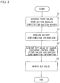
- Fig. 3 is a flow chart which describes the flow of a calculation process of the set value for controlling the charge/discharge of the storage battery 10 executed by the battery controller 30 according to the embodiment.
- the process in the present flow chart starts, for example, when the electricity storage system 1 is activated.
- the characteristic acquirer 32 acquires the fixed values representing the physical values, which represent the physical characteristics of each of the battery modules 14, from each of the plurality of battery modules 14 constituting the storage battery 10 (S2).
- the configuration information acquirer 34 acquires the battery configuration information representing the connection form of the plurality of battery modules 14 constituting the storage battery 10 (S4).
- the calculator 33 calculates the set value for controlling the charge/discharge of the storage battery 10 based on the fixed values of the battery modules 14 acquired by the characteristic acquirer 32 and the battery configuration information acquired by the configuration information acquirer 34 (S6).
- the output unit 35 outputs the set value, which is calculated by the calculator 33 and is for controlling the charge/discharge of the storage battery 10, to the charge/discharge controller 20 (S8). When the output unit 35 outputs the set value to the charge/discharge controller 20, the process of the present flow chart is finished.
- the set value for controlling the charge/discharge of the storage battery 10 can be dynamically calculated.
- the set value of the storage battery 10 for controlling the charge/discharge of the storage battery 10 can be automatically calculated. As a result, only the storage battery 10 can be replaced without replacing the electricity storage system 1 per se, and the charge/discharge control of the storage battery 10 can be executed.
- the calculator 33 calculates the set value, which is for controlling the charge/discharge of the storage battery 10, based on the fixed values, which represent the physical characteristics of the individual battery modules 14 acquired by the characteristic acquirer 32, and the battery configuration information, which has been acquired by the configuration information acquirer 34 and acquired from the user via the operation panel 40.
- the battery configuration information can be also acquired by deriving by the calculator 33 based on other information without acquiring the battery configuration information from the user.
- this case will be described.
- the characteristic acquirer 32 can discriminate the battery modules 14 by using the addresses. Therefore, the characteristic acquirer 32 can specify the number of the battery modules 14 connected to the particular communication lines 60, in other words, the series number Ns by counting the number of the different addresses.
- the calculator 33 acquires the battery configuration information by acquiring the number of the communication lines 60 as the parallel number Np and acquiring the number of the battery modules 14 connected to each of the communication lines 60 as the series number Ns.
- the above described first modification is on the assumption that each battery block 12 is connected via each communication line 60 to the connector 31 of the storage battery 10.
- the first modification is on the assumption that the number of the communication lines 60 and the number of the parallel number Np match.
- a case in which the number of the communication lines 60 and the number of the parallel number Np do not match is also possible.
- the number of the communication lines 60 and the number of the parallel number Np do not match.
- the calculator 33 utilizes the characteristic information of the battery modules 14 including the measured values of the current physical characteristics of the battery modules 14 in addition to the fixed values representing the physical characteristics of the battery modules 14 acquired by the characteristic acquirer 32 to calculate the battery configuration information.
- the characteristic information of the battery modules 14 including the measured values of the current physical characteristics of the battery modules 14 in addition to the fixed values representing the physical characteristics of the battery modules 14 acquired by the characteristic acquirer 32 to calculate the battery configuration information.
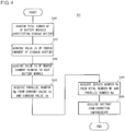
- Fig. 4 is a flow chart describing the flow of the calculation process of the battery configuration information executed by the battery controller 30 according to the embodiment and is a chart describing the flow of the process of step S4 of Fig. 3 in more detail.
- the characteristic acquirer 32 totals the number of the battery modules 14 connected to the communication lines 60 to acquire the total number Nt of the battery modules 14 constituting the storage battery 10 (S40). This can be realized by counting the number of the different addresses by the characteristic acquirer 32 as described above.
- the calculator 33 acquires, from the charge/discharge controller 20, the value Ib of the charge current input to the storage battery 10 (S42).
- the characteristic acquirer 32 acquires, via the communication line 60, the value Iu of the charge current flowing to each of the battery modules 14 (S44).
- the calculator 33 calculates the parallel number Np based on the value Ib of the charge current input to the storage battery 10 by the charge/discharge controller 20 and the value Im of the charge current acquired by the characteristic acquirer 32 and flowing to each of the battery modules 14 (S46).
- the charge current Im flowing to each of the battery modules 14 is the value obtained by dividing the value Ib of the charge current input to the storage battery 10 from the charge/discharge controller 20 by the parallel number Np. Therefore, the calculator 33 calculates the parallel number Np by dividing the value Ib of the charge current input to the storage battery 10 by the charge/discharge controller 20 by the value Im of the charge current flowing to each of the battery modules 14.
- the calculator 33 calculates the series number Ns based on the calculated parallel number Np and the total number Nt of the battery modules 14 connected to the communication line 60 (S48) .
- the number of the battery modules 14 included in each of the electricity storage blocks is the same. Therefore, the calculator 33 calculates the series number Ns by dividing the total number Nt of the battery modules 14 connected to the communication lines 60 by the parallel number Np.
- the calculator 33 acquires the battery configuration information including the parallel number Np and the series number Ns (S50). When the calculator 33 acquires the battery configuration information, the process of the present flow chart is finished.
- the calculator 33 can calculate the battery configuration information by utilizing the characteristic information of the battery modules 14. By virtue of this, even in a case in which the number of the communication lines 60 and the parallel number Np do not match, for example, when all the battery modules 14 are connected by the single communication line 60, the calculator 33 can automatically acquire the battery configuration information.
- 1 electricity storage system 2 system power source, 10 storage battery, 12 battery block, 14 battery module, 20 charge/discharge controller, 30 battery controller, 31 connector, 32 characteristic acquirer, 33 calculator, 34 configuration information acquirer, 35 output unit, 40 operation panel, 50 electric power line, 60 communication line.
- the present invention can be utilized in an electricity storage system including a plurality of battery modules.
Landscapes
- Engineering & Computer Science (AREA)
- Power Engineering (AREA)
- Life Sciences & Earth Sciences (AREA)
- Sustainable Development (AREA)
- Sustainable Energy (AREA)
- Transportation (AREA)
- Mechanical Engineering (AREA)
- Charge And Discharge Circuits For Batteries Or The Like (AREA)
- Secondary Cells (AREA)
Claims (3)
- Steuerungsvorrichtung (30), aufweisend:mehrere Steckverbinder (31a, 31b, 31c), die mit einer Speicherbatterie (10) verbunden sind, die mehrere Batterieblöcke (12a, 12b) enthält, die parallel geschaltet sind, wobei jeder Batterieblock (12a, 12b) mit zwei oder mehreren Batteriemodulen (14a, 14b,..., 14h) gebildet ist, die in Serie geschaltet sind, und wobei jeder Steckverbinder (31a, 31b, 31c) über eine entsprechende Kommunikationsleitung (60a, 60b) mit einem entsprechenden der Batterieblöcke (12a, 12b) verbunden ist;einen Charakteristikerfasser (32), der dafür ausgelegt ist, Charakteristikinformationen aufzunehmen, die eine physikalische Charakteristik jedes der mehreren Batteriemodule (14a, 14b,...., 14h) angeben;ein Rechner (33), der dafür ausgelegt ist, einen Einstellwert zum Steuern des Ladens/Entladens der Speicherbatterie (10) zu berechnen, basierend auf den Charakteristikinformationen jedes Batteriemoduls (14a, 14b,..., 14h), die von dem Charakteristikerfasser (32) erfasst sind, Batteriekonfigurationsinformationen, die eine Verbindungsform der mehreren Batteriemodule (14a, 14b,..., 14h) angeben, die die Speicherbatterie (10) bilden, und auf einem Einstellwert, der die physikalische Charakteristik jedes Batteriemoduls (14a, 14b,..., 14h) angibt, wobei die Batteriekonfigurationsinformationen Informationen, die eine Parallelanzahl, die die Anzahl der Kommunikationsleitungen (60a, 60b) angibt, und eine Seriellanzahl, die die Anzahl der Batteriemodule (14a, 14b,..., 14h) angibt, die an jede Kommunikationsleitung (60a, 60b) angeschlossen sind, beinhalten; undeine Ausgabeeinheit, die den von dem Rechner (33) berechneten Einstellwert an eine Lade-/ Entladesteuerungsvorrichtung (20) ausgibt, die das Laden/Entladen der Speicherbatterie (10) steuert.
- Elektrisches Speichersystem (1), aufweisend:eine Speicherbatterie (10), die mehrere Batterieblöcke (12a, 12b) enthält, die parallel geschaltet sind, wobei jeder Batterieblock (12a, 12b) mit zwei oder mehreren Batteriemodulen (14a, 14b,...., 14h), die in Serie geschaltet sind, gebildet ist;eine Batteriesteuerungsvorrichtung (30), die über eine entsprechende Kommunikationsleitung (60a, 60b) mit jedem Batterieblock (12a, 12b) verbunden ist; undeine Lade-/Entladesteuerungsvorrichtung (20), die über eine elektrische Stromleitung (50) mit der Speicherbatterie (10) verbunden ist,wobei die Batteriesteuerungsvorrichtung (30) eine Steuerungsvorrichtung nach Anspruch 1 ist.
- Steuerungsverfahren für eine Speicherbatterie (10), die mehrere parallel geschaltete Batterieblöcke (12a, 12b) aufweist, wobei jeder Batterieblock (12a, 12b) mit zwei oder mehreren Batteriemodulen (14a, 14b,..., 14h) gebildet ist, die in Serie geschaltet sind, wobei das Steuerungsverfahren die folgenden Schritte umfasst, die von einer Steuerungsvorrichtung (30) durchgeführt werden, die mehrere Steckverbindern (31a, 31b, 31c) aufweist, von denen jeder über eine entsprechende Kommunikationsleitung (60a, 60b) mit einem entsprechenden Batterieblock (12a, 12b) verbunden ist:Erfassen von Charakteristikinformationen, die eine physikalische Charakteristik jedes der mehreren Batteriemodule (14a, 14b,...., 14h) angeben;Berechnen eines Einstellwerts zum Steuern des Ladens/Entladens der Speicherbatterie (10) basierend auf den erfassten Charakteristikinformationen jedes Batteriemoduls (14a, 14b,..., 14h)), Batteriekonfigurationsinformationen, die eine Verbindungsform der mehreren Batteriemodule (14a, 14b,..., 14h), die die Speicherbatterie (10) bilden, angeben, und auf einem Einstellwert, der die physikalische Charakteristik jedes Batteriemoduls (14a, 14b, 14b,..., 14h) angibt, wobei die Batteriekonfigurationsinformationen Informationen beinhalten, die eine Parallelanzahl, die die Anzahl der Kommunikationsleitungen (60a, 60b) angibt, und eine Seriellanzahl, die die Anzahl der Batteriemodule (14a, 14b,..., 14h) angibt, die mit jeder Kommunikationsleitung (60a, 60b) verbunden sind; undSteuern des Ladens/Entladens der Speicherbatterie (10) basierend auf dem berechneten Einstellwert.
Applications Claiming Priority (2)
| Application Number | Priority Date | Filing Date | Title |
|---|---|---|---|
| JP2014196966A JP6403112B2 (ja) | 2014-09-26 | 2014-09-26 | 蓄電システムおよび制御装置 |
| PCT/JP2015/004267 WO2016047040A1 (ja) | 2014-09-26 | 2015-08-25 | 蓄電システム、制御装置、および制御方法 |
Publications (3)
| Publication Number | Publication Date |
|---|---|
| EP3200310A1 EP3200310A1 (de) | 2017-08-02 |
| EP3200310A4 EP3200310A4 (de) | 2017-09-20 |
| EP3200310B1 true EP3200310B1 (de) | 2019-07-03 |
Family
ID=55580594
Family Applications (1)
| Application Number | Title | Priority Date | Filing Date |
|---|---|---|---|
| EP15844310.1A Not-in-force EP3200310B1 (de) | 2014-09-26 | 2015-08-25 | Elektrisches speichersystem, steuerungsvorrichtung und steuerungsverfahren |
Country Status (4)
| Country | Link |
|---|---|
| EP (1) | EP3200310B1 (de) |
| JP (1) | JP6403112B2 (de) |
| AU (1) | AU2015323230B2 (de) |
| WO (1) | WO2016047040A1 (de) |
Families Citing this family (7)
| Publication number | Priority date | Publication date | Assignee | Title |
|---|---|---|---|---|
| JP2016185044A (ja) * | 2015-03-26 | 2016-10-20 | パナソニックIpマネジメント株式会社 | 蓄電池管理装置、制御装置、蓄電池モジュール、および蓄電池管理方法 |
| JP6618443B2 (ja) * | 2016-09-21 | 2019-12-11 | 株式会社エンビジョンAescジャパン | 電源システムの充電停止方法 |
| JP6950314B2 (ja) * | 2017-07-13 | 2021-10-13 | 株式会社豊田自動織機 | 電池パック |
| CN111993953B (zh) * | 2020-08-27 | 2021-10-29 | 安徽江淮汽车集团股份有限公司 | 电池控制方法、动力汽车及可读存储介质 |
| JP7581156B2 (ja) * | 2021-08-23 | 2024-11-12 | 株式会社日立製作所 | 組電池システム及びエネルギー貯蔵システム |
| CN116826209A (zh) * | 2023-07-04 | 2023-09-29 | 深圳市龙星辰电源有限公司 | 获取电池包内电池连接的方法、系统、存储介质及设备 |
| JP7738152B1 (ja) * | 2024-10-21 | 2025-09-11 | 威盛電子股▲ふん▼有限公司 | 充放電システム及び充放電方法 |
Family Cites Families (5)
| Publication number | Priority date | Publication date | Assignee | Title |
|---|---|---|---|---|
| JP4512062B2 (ja) * | 2006-06-02 | 2010-07-28 | Necトーキン株式会社 | 複数のリチウムイオン二次電池を直列接続した組電池の電圧バランス調整法 |
| JP2011113759A (ja) * | 2009-11-25 | 2011-06-09 | Diamond Electric Mfg Co Ltd | バッテリー管理装置とバッテリー管理方法 |
| US9595847B2 (en) * | 2010-11-04 | 2017-03-14 | Elite Power Solutions Llc | Uninterrupted lithium battery power supply system |
| JP2013101831A (ja) * | 2011-11-08 | 2013-05-23 | Sanyo Electric Co Ltd | 電源システム、電池ユニット及び電源システムの異常時動作確認方法 |
| EP2907218A4 (de) * | 2012-10-09 | 2016-06-08 | J B Wright | Intelligentes verteiltes batteriesystem und verfahren |
-
2014
- 2014-09-26 JP JP2014196966A patent/JP6403112B2/ja active Active
-
2015
- 2015-08-25 WO PCT/JP2015/004267 patent/WO2016047040A1/ja not_active Ceased
- 2015-08-25 AU AU2015323230A patent/AU2015323230B2/en active Active
- 2015-08-25 EP EP15844310.1A patent/EP3200310B1/de not_active Not-in-force
Non-Patent Citations (1)
| Title |
|---|
| None * |
Also Published As
| Publication number | Publication date |
|---|---|
| AU2015323230B2 (en) | 2018-12-06 |
| AU2015323230A1 (en) | 2017-04-13 |
| EP3200310A1 (de) | 2017-08-02 |
| JP2016073009A (ja) | 2016-05-09 |
| EP3200310A4 (de) | 2017-09-20 |
| JP6403112B2 (ja) | 2018-10-10 |
| WO2016047040A1 (ja) | 2016-03-31 |
Similar Documents
| Publication | Publication Date | Title |
|---|---|---|
| US8232768B2 (en) | System and method for balancing battery cells | |
| AU2015323230B2 (en) | Electrical storage system, control apparatus, and control method | |
| EP3054554B1 (de) | Batteriepack und verfahren zu dessen steuerung | |
| US9401616B2 (en) | Battery pack, energy storage system including battery pack, and method of charging battery pack | |
| CN107750413B (zh) | 控制装置、蓄电装置及蓄电系统 | |
| US9431684B2 (en) | Master-slave type battery management system for accurate capacity guage of battery pack | |
| US7956579B2 (en) | Battery charge management system for charging a battery bank that includes a plurality of batteries | |
| US20170214266A1 (en) | Electric power storage device, control device, electric power storage system, method for controlling electric power storage device, and non-transitory computer-readable medium storing control program | |
| US11205910B2 (en) | Method for charging or discharging an energy store | |
| US20130154569A1 (en) | Electric energy storage system and method of maintaining the same | |
| EP2629388A1 (de) | Leistungsverwaltungssystem | |
| US20140079963A1 (en) | Battery System Control Method | |
| KR20130124881A (ko) | 배터리 관리 시스템 및 이를 포함하는 에너지 저장 시스템 | |
| JPWO2012157747A1 (ja) | 組電池の制御方法及び制御装置 | |
| CN108808776A (zh) | 一种电池系统及电池健康状态的检测方法 | |
| CN115101840B (zh) | 电池系统和电池包连接状态识别方法 | |
| KR102622789B1 (ko) | 모듈식 배터리 관리 시스템 | |
| JP5314626B2 (ja) | 電源システム、放電制御方法および放電制御プログラム | |
| TWI492482B (zh) | 用於準確量測電池容量的主僕式電池管理系統 | |
| JP5489779B2 (ja) | リチウムイオン組電池の充電システムおよび充電方法 | |
| US20250317000A1 (en) | Charge/discharge control device, charge/discharge control method, and program | |
| KR20180049545A (ko) | 멀티 충전이 가능한 배터리팩과 배터리팩 확장성을 고려한 에너지 저장 시스템 | |
| EP4053966A1 (de) | Stromspeichersystem und verwaltungsverfahren | |
| US12348067B2 (en) | Reconfigurable battery pack | |
| WO2018157534A1 (zh) | 储能电池管理系统的均衡方法、装置、储能电池管理系统 |
Legal Events
| Date | Code | Title | Description |
|---|---|---|---|
| STAA | Information on the status of an ep patent application or granted ep patent |
Free format text: STATUS: THE INTERNATIONAL PUBLICATION HAS BEEN MADE |
|
| PUAI | Public reference made under article 153(3) epc to a published international application that has entered the european phase |
Free format text: ORIGINAL CODE: 0009012 |
|
| STAA | Information on the status of an ep patent application or granted ep patent |
Free format text: STATUS: REQUEST FOR EXAMINATION WAS MADE |
|
| 17P | Request for examination filed |
Effective date: 20170321 |
|
| AK | Designated contracting states |
Kind code of ref document: A1 Designated state(s): AL AT BE BG CH CY CZ DE DK EE ES FI FR GB GR HR HU IE IS IT LI LT LU LV MC MK MT NL NO PL PT RO RS SE SI SK SM TR |
|
| AX | Request for extension of the european patent |
Extension state: BA ME |
|
| A4 | Supplementary search report drawn up and despatched |
Effective date: 20170823 |
|
| RIC1 | Information provided on ipc code assigned before grant |
Ipc: H02J 7/00 20060101AFI20170817BHEP Ipc: H02J 7/02 20160101ALI20170817BHEP Ipc: H01M 10/44 20060101ALI20170817BHEP Ipc: B60L 11/18 20060101ALI20170817BHEP |
|
| DAV | Request for validation of the european patent (deleted) | ||
| DAX | Request for extension of the european patent (deleted) | ||
| GRAP | Despatch of communication of intention to grant a patent |
Free format text: ORIGINAL CODE: EPIDOSNIGR1 |
|
| STAA | Information on the status of an ep patent application or granted ep patent |
Free format text: STATUS: GRANT OF PATENT IS INTENDED |
|
| INTG | Intention to grant announced |
Effective date: 20190109 |
|
| GRAJ | Information related to disapproval of communication of intention to grant by the applicant or resumption of examination proceedings by the epo deleted |
Free format text: ORIGINAL CODE: EPIDOSDIGR1 |
|
| STAA | Information on the status of an ep patent application or granted ep patent |
Free format text: STATUS: REQUEST FOR EXAMINATION WAS MADE |
|
| GRAR | Information related to intention to grant a patent recorded |
Free format text: ORIGINAL CODE: EPIDOSNIGR71 |
|
| GRAS | Grant fee paid |
Free format text: ORIGINAL CODE: EPIDOSNIGR3 |
|
| STAA | Information on the status of an ep patent application or granted ep patent |
Free format text: STATUS: GRANT OF PATENT IS INTENDED |
|
| GRAA | (expected) grant |
Free format text: ORIGINAL CODE: 0009210 |
|
| STAA | Information on the status of an ep patent application or granted ep patent |
Free format text: STATUS: THE PATENT HAS BEEN GRANTED |
|
| INTC | Intention to grant announced (deleted) | ||
| RIC1 | Information provided on ipc code assigned before grant |
Ipc: H02J 7/02 20160101ALI20190515BHEP Ipc: B60L 58/10 20190101ALI20190515BHEP Ipc: H01M 10/44 20060101ALI20190515BHEP Ipc: H02J 7/00 20060101AFI20190515BHEP |
|
| AK | Designated contracting states |
Kind code of ref document: B1 Designated state(s): AL AT BE BG CH CY CZ DE DK EE ES FI FR GB GR HR HU IE IS IT LI LT LU LV MC MK MT NL NO PL PT RO RS SE SI SK SM TR |
|
| INTG | Intention to grant announced |
Effective date: 20190524 |
|
| REG | Reference to a national code |
Ref country code: GB Ref legal event code: FG4D |
|
| REG | Reference to a national code |
Ref country code: CH Ref legal event code: EP Ref country code: AT Ref legal event code: REF Ref document number: 1152147 Country of ref document: AT Kind code of ref document: T Effective date: 20190715 |
|
| REG | Reference to a national code |
Ref country code: DE Ref legal event code: R096 Ref document number: 602015033304 Country of ref document: DE |
|
| REG | Reference to a national code |
Ref country code: IE Ref legal event code: FG4D |
|
| REG | Reference to a national code |
Ref country code: NL Ref legal event code: MP Effective date: 20190703 |
|
| REG | Reference to a national code |
Ref country code: LT Ref legal event code: MG4D |
|
| REG | Reference to a national code |
Ref country code: AT Ref legal event code: MK05 Ref document number: 1152147 Country of ref document: AT Kind code of ref document: T Effective date: 20190703 |
|
| PG25 | Lapsed in a contracting state [announced via postgrant information from national office to epo] |
Ref country code: FI Free format text: LAPSE BECAUSE OF FAILURE TO SUBMIT A TRANSLATION OF THE DESCRIPTION OR TO PAY THE FEE WITHIN THE PRESCRIBED TIME-LIMIT Effective date: 20190703 Ref country code: AT Free format text: LAPSE BECAUSE OF FAILURE TO SUBMIT A TRANSLATION OF THE DESCRIPTION OR TO PAY THE FEE WITHIN THE PRESCRIBED TIME-LIMIT Effective date: 20190703 Ref country code: NO Free format text: LAPSE BECAUSE OF FAILURE TO SUBMIT A TRANSLATION OF THE DESCRIPTION OR TO PAY THE FEE WITHIN THE PRESCRIBED TIME-LIMIT Effective date: 20191003 Ref country code: BG Free format text: LAPSE BECAUSE OF FAILURE TO SUBMIT A TRANSLATION OF THE DESCRIPTION OR TO PAY THE FEE WITHIN THE PRESCRIBED TIME-LIMIT Effective date: 20191003 Ref country code: SE Free format text: LAPSE BECAUSE OF FAILURE TO SUBMIT A TRANSLATION OF THE DESCRIPTION OR TO PAY THE FEE WITHIN THE PRESCRIBED TIME-LIMIT Effective date: 20190703 Ref country code: PT Free format text: LAPSE BECAUSE OF FAILURE TO SUBMIT A TRANSLATION OF THE DESCRIPTION OR TO PAY THE FEE WITHIN THE PRESCRIBED TIME-LIMIT Effective date: 20191104 Ref country code: CZ Free format text: LAPSE BECAUSE OF FAILURE TO SUBMIT A TRANSLATION OF THE DESCRIPTION OR TO PAY THE FEE WITHIN THE PRESCRIBED TIME-LIMIT Effective date: 20190703 Ref country code: NL Free format text: LAPSE BECAUSE OF FAILURE TO SUBMIT A TRANSLATION OF THE DESCRIPTION OR TO PAY THE FEE WITHIN THE PRESCRIBED TIME-LIMIT Effective date: 20190703 Ref country code: LT Free format text: LAPSE BECAUSE OF FAILURE TO SUBMIT A TRANSLATION OF THE DESCRIPTION OR TO PAY THE FEE WITHIN THE PRESCRIBED TIME-LIMIT Effective date: 20190703 Ref country code: HR Free format text: LAPSE BECAUSE OF FAILURE TO SUBMIT A TRANSLATION OF THE DESCRIPTION OR TO PAY THE FEE WITHIN THE PRESCRIBED TIME-LIMIT Effective date: 20190703 |
|
| PG25 | Lapsed in a contracting state [announced via postgrant information from national office to epo] |
Ref country code: IS Free format text: LAPSE BECAUSE OF FAILURE TO SUBMIT A TRANSLATION OF THE DESCRIPTION OR TO PAY THE FEE WITHIN THE PRESCRIBED TIME-LIMIT Effective date: 20191103 Ref country code: LV Free format text: LAPSE BECAUSE OF FAILURE TO SUBMIT A TRANSLATION OF THE DESCRIPTION OR TO PAY THE FEE WITHIN THE PRESCRIBED TIME-LIMIT Effective date: 20190703 Ref country code: RS Free format text: LAPSE BECAUSE OF FAILURE TO SUBMIT A TRANSLATION OF THE DESCRIPTION OR TO PAY THE FEE WITHIN THE PRESCRIBED TIME-LIMIT Effective date: 20190703 Ref country code: AL Free format text: LAPSE BECAUSE OF FAILURE TO SUBMIT A TRANSLATION OF THE DESCRIPTION OR TO PAY THE FEE WITHIN THE PRESCRIBED TIME-LIMIT Effective date: 20190703 Ref country code: ES Free format text: LAPSE BECAUSE OF FAILURE TO SUBMIT A TRANSLATION OF THE DESCRIPTION OR TO PAY THE FEE WITHIN THE PRESCRIBED TIME-LIMIT Effective date: 20190703 Ref country code: GR Free format text: LAPSE BECAUSE OF FAILURE TO SUBMIT A TRANSLATION OF THE DESCRIPTION OR TO PAY THE FEE WITHIN THE PRESCRIBED TIME-LIMIT Effective date: 20191004 |
|
| PG25 | Lapsed in a contracting state [announced via postgrant information from national office to epo] |
Ref country code: TR Free format text: LAPSE BECAUSE OF FAILURE TO SUBMIT A TRANSLATION OF THE DESCRIPTION OR TO PAY THE FEE WITHIN THE PRESCRIBED TIME-LIMIT Effective date: 20190703 |
|
| PG25 | Lapsed in a contracting state [announced via postgrant information from national office to epo] |
Ref country code: EE Free format text: LAPSE BECAUSE OF FAILURE TO SUBMIT A TRANSLATION OF THE DESCRIPTION OR TO PAY THE FEE WITHIN THE PRESCRIBED TIME-LIMIT Effective date: 20190703 Ref country code: PL Free format text: LAPSE BECAUSE OF FAILURE TO SUBMIT A TRANSLATION OF THE DESCRIPTION OR TO PAY THE FEE WITHIN THE PRESCRIBED TIME-LIMIT Effective date: 20190703 Ref country code: DK Free format text: LAPSE BECAUSE OF FAILURE TO SUBMIT A TRANSLATION OF THE DESCRIPTION OR TO PAY THE FEE WITHIN THE PRESCRIBED TIME-LIMIT Effective date: 20190703 Ref country code: IT Free format text: LAPSE BECAUSE OF FAILURE TO SUBMIT A TRANSLATION OF THE DESCRIPTION OR TO PAY THE FEE WITHIN THE PRESCRIBED TIME-LIMIT Effective date: 20190703 Ref country code: RO Free format text: LAPSE BECAUSE OF FAILURE TO SUBMIT A TRANSLATION OF THE DESCRIPTION OR TO PAY THE FEE WITHIN THE PRESCRIBED TIME-LIMIT Effective date: 20190703 |
|
| PG25 | Lapsed in a contracting state [announced via postgrant information from national office to epo] |
Ref country code: IS Free format text: LAPSE BECAUSE OF FAILURE TO SUBMIT A TRANSLATION OF THE DESCRIPTION OR TO PAY THE FEE WITHIN THE PRESCRIBED TIME-LIMIT Effective date: 20200224 Ref country code: SK Free format text: LAPSE BECAUSE OF FAILURE TO SUBMIT A TRANSLATION OF THE DESCRIPTION OR TO PAY THE FEE WITHIN THE PRESCRIBED TIME-LIMIT Effective date: 20190703 Ref country code: SM Free format text: LAPSE BECAUSE OF FAILURE TO SUBMIT A TRANSLATION OF THE DESCRIPTION OR TO PAY THE FEE WITHIN THE PRESCRIBED TIME-LIMIT Effective date: 20190703 Ref country code: LI Free format text: LAPSE BECAUSE OF NON-PAYMENT OF DUE FEES Effective date: 20190831 Ref country code: MC Free format text: LAPSE BECAUSE OF FAILURE TO SUBMIT A TRANSLATION OF THE DESCRIPTION OR TO PAY THE FEE WITHIN THE PRESCRIBED TIME-LIMIT Effective date: 20190703 Ref country code: LU Free format text: LAPSE BECAUSE OF NON-PAYMENT OF DUE FEES Effective date: 20190825 Ref country code: CH Free format text: LAPSE BECAUSE OF NON-PAYMENT OF DUE FEES Effective date: 20190831 |
|
| REG | Reference to a national code |
Ref country code: BE Ref legal event code: MM Effective date: 20190831 |
|
| REG | Reference to a national code |
Ref country code: DE Ref legal event code: R097 Ref document number: 602015033304 Country of ref document: DE |
|
| PLBE | No opposition filed within time limit |
Free format text: ORIGINAL CODE: 0009261 |
|
| STAA | Information on the status of an ep patent application or granted ep patent |
Free format text: STATUS: NO OPPOSITION FILED WITHIN TIME LIMIT |
|
| PG2D | Information on lapse in contracting state deleted |
Ref country code: IS |
|
| PG25 | Lapsed in a contracting state [announced via postgrant information from national office to epo] |
Ref country code: FR Free format text: LAPSE BECAUSE OF NON-PAYMENT OF DUE FEES Effective date: 20190903 Ref country code: IE Free format text: LAPSE BECAUSE OF NON-PAYMENT OF DUE FEES Effective date: 20190825 |
|
| 26N | No opposition filed |
Effective date: 20200603 |
|
| PG25 | Lapsed in a contracting state [announced via postgrant information from national office to epo] |
Ref country code: SI Free format text: LAPSE BECAUSE OF FAILURE TO SUBMIT A TRANSLATION OF THE DESCRIPTION OR TO PAY THE FEE WITHIN THE PRESCRIBED TIME-LIMIT Effective date: 20190703 Ref country code: BE Free format text: LAPSE BECAUSE OF NON-PAYMENT OF DUE FEES Effective date: 20190831 |
|
| GBPC | Gb: european patent ceased through non-payment of renewal fee |
Effective date: 20191003 |
|
| PG25 | Lapsed in a contracting state [announced via postgrant information from national office to epo] |
Ref country code: GB Free format text: LAPSE BECAUSE OF NON-PAYMENT OF DUE FEES Effective date: 20191003 |
|
| PG25 | Lapsed in a contracting state [announced via postgrant information from national office to epo] |
Ref country code: CY Free format text: LAPSE BECAUSE OF FAILURE TO SUBMIT A TRANSLATION OF THE DESCRIPTION OR TO PAY THE FEE WITHIN THE PRESCRIBED TIME-LIMIT Effective date: 20190703 |
|
| PG25 | Lapsed in a contracting state [announced via postgrant information from national office to epo] |
Ref country code: HU Free format text: LAPSE BECAUSE OF FAILURE TO SUBMIT A TRANSLATION OF THE DESCRIPTION OR TO PAY THE FEE WITHIN THE PRESCRIBED TIME-LIMIT; INVALID AB INITIO Effective date: 20150825 Ref country code: MT Free format text: LAPSE BECAUSE OF FAILURE TO SUBMIT A TRANSLATION OF THE DESCRIPTION OR TO PAY THE FEE WITHIN THE PRESCRIBED TIME-LIMIT Effective date: 20190703 |
|
| PG25 | Lapsed in a contracting state [announced via postgrant information from national office to epo] |
Ref country code: MK Free format text: LAPSE BECAUSE OF FAILURE TO SUBMIT A TRANSLATION OF THE DESCRIPTION OR TO PAY THE FEE WITHIN THE PRESCRIBED TIME-LIMIT Effective date: 20190703 |
|
| PGFP | Annual fee paid to national office [announced via postgrant information from national office to epo] |
Ref country code: DE Payment date: 20220819 Year of fee payment: 8 |
|
| REG | Reference to a national code |
Ref country code: DE Ref legal event code: R119 Ref document number: 602015033304 Country of ref document: DE |
|
| PG25 | Lapsed in a contracting state [announced via postgrant information from national office to epo] |
Ref country code: DE Free format text: LAPSE BECAUSE OF NON-PAYMENT OF DUE FEES Effective date: 20240301 |