EP3200327A1 - Machine électrique refroidie par air - Google Patents
Machine électrique refroidie par air Download PDFInfo
- Publication number
- EP3200327A1 EP3200327A1 EP17153168.4A EP17153168A EP3200327A1 EP 3200327 A1 EP3200327 A1 EP 3200327A1 EP 17153168 A EP17153168 A EP 17153168A EP 3200327 A1 EP3200327 A1 EP 3200327A1
- Authority
- EP
- European Patent Office
- Prior art keywords
- fan
- machine
- electric machine
- coupling part
- air
- Prior art date
- Legal status (The legal status is an assumption and is not a legal conclusion. Google has not performed a legal analysis and makes no representation as to the accuracy of the status listed.)
- Granted
Links
Images


Classifications
-
- H—ELECTRICITY
- H02—GENERATION; CONVERSION OR DISTRIBUTION OF ELECTRIC POWER
- H02K—DYNAMO-ELECTRIC MACHINES
- H02K7/00—Arrangements for handling mechanical energy structurally associated with dynamo-electric machines, e.g. structural association with mechanical driving motors or auxiliary dynamo-electric machines
- H02K7/003—Couplings; Details of shafts
-
- F—MECHANICAL ENGINEERING; LIGHTING; HEATING; WEAPONS; BLASTING
- F16—ENGINEERING ELEMENTS AND UNITS; GENERAL MEASURES FOR PRODUCING AND MAINTAINING EFFECTIVE FUNCTIONING OF MACHINES OR INSTALLATIONS; THERMAL INSULATION IN GENERAL
- F16D—COUPLINGS FOR TRANSMITTING ROTATION; CLUTCHES; BRAKES
- F16D3/00—Yielding couplings, i.e. with means permitting movement between the connected parts during the drive
- F16D3/16—Universal joints in which flexibility is produced by means of pivots or sliding or rolling connecting parts
- F16D3/18—Universal joints in which flexibility is produced by means of pivots or sliding or rolling connecting parts the coupling parts (1) having slidably-interengaging teeth
- F16D3/185—Universal joints in which flexibility is produced by means of pivots or sliding or rolling connecting parts the coupling parts (1) having slidably-interengaging teeth radial teeth connecting concentric inner and outer coupling parts
-
- H—ELECTRICITY
- H02—GENERATION; CONVERSION OR DISTRIBUTION OF ELECTRIC POWER
- H02K—DYNAMO-ELECTRIC MACHINES
- H02K1/00—Details of the magnetic circuit
- H02K1/06—Details of the magnetic circuit characterised by the shape, form or construction
- H02K1/12—Stationary parts of the magnetic circuit
- H02K1/20—Stationary parts of the magnetic circuit with channels or ducts for flow of cooling medium
-
- H—ELECTRICITY
- H02—GENERATION; CONVERSION OR DISTRIBUTION OF ELECTRIC POWER
- H02K—DYNAMO-ELECTRIC MACHINES
- H02K9/00—Arrangements for cooling or ventilating
- H02K9/02—Arrangements for cooling or ventilating by ambient air flowing through the machine
- H02K9/04—Arrangements for cooling or ventilating by ambient air flowing through the machine having means for generating a flow of cooling medium
- H02K9/06—Arrangements for cooling or ventilating by ambient air flowing through the machine having means for generating a flow of cooling medium with fans or impellers driven by the machine shaft
-
- H—ELECTRICITY
- H02—GENERATION; CONVERSION OR DISTRIBUTION OF ELECTRIC POWER
- H02K—DYNAMO-ELECTRIC MACHINES
- H02K9/00—Arrangements for cooling or ventilating
- H02K9/14—Arrangements for cooling or ventilating wherein gaseous cooling medium circulates between the machine casing and a surrounding mantle
- H02K9/16—Arrangements for cooling or ventilating wherein gaseous cooling medium circulates between the machine casing and a surrounding mantle wherein the cooling medium circulates through ducts or tubes within the casing
-
- F—MECHANICAL ENGINEERING; LIGHTING; HEATING; WEAPONS; BLASTING
- F16—ENGINEERING ELEMENTS AND UNITS; GENERAL MEASURES FOR PRODUCING AND MAINTAINING EFFECTIVE FUNCTIONING OF MACHINES OR INSTALLATIONS; THERMAL INSULATION IN GENERAL
- F16D—COUPLINGS FOR TRANSMITTING ROTATION; CLUTCHES; BRAKES
- F16D13/00—Friction clutches
- F16D13/76—Friction clutches specially adapted to incorporate with other transmission parts, i.e. at least one of the clutch parts also having another function, e.g. being the disc of a pulley
-
- F—MECHANICAL ENGINEERING; LIGHTING; HEATING; WEAPONS; BLASTING
- F16—ENGINEERING ELEMENTS AND UNITS; GENERAL MEASURES FOR PRODUCING AND MAINTAINING EFFECTIVE FUNCTIONING OF MACHINES OR INSTALLATIONS; THERMAL INSULATION IN GENERAL
- F16D—COUPLINGS FOR TRANSMITTING ROTATION; CLUTCHES; BRAKES
- F16D2300/00—Special features for couplings or clutches
- F16D2300/02—Overheat protection, i.e. means for protection against overheating
- F16D2300/021—Cooling features not provided for in group F16D13/72 or F16D25/123, e.g. heat transfer details
- F16D2300/0212—Air cooling
-
- F—MECHANICAL ENGINEERING; LIGHTING; HEATING; WEAPONS; BLASTING
- F16—ENGINEERING ELEMENTS AND UNITS; GENERAL MEASURES FOR PRODUCING AND MAINTAINING EFFECTIVE FUNCTIONING OF MACHINES OR INSTALLATIONS; THERMAL INSULATION IN GENERAL
- F16D—COUPLINGS FOR TRANSMITTING ROTATION; CLUTCHES; BRAKES
- F16D2300/00—Special features for couplings or clutches
- F16D2300/08—Details or arrangements of sealings not provided for in group F16D3/84
-
- H—ELECTRICITY
- H02—GENERATION; CONVERSION OR DISTRIBUTION OF ELECTRIC POWER
- H02K—DYNAMO-ELECTRIC MACHINES
- H02K7/00—Arrangements for handling mechanical energy structurally associated with dynamo-electric machines, e.g. structural association with mechanical driving motors or auxiliary dynamo-electric machines
- H02K7/10—Structural association with clutches, brakes, gears, pulleys or mechanical starters
- H02K7/116—Structural association with clutches, brakes, gears, pulleys or mechanical starters with gears
Definitions
- the invention relates to an air-cooled electric machine having a rotatably connected to a rotor shaft rotor, a stator with axially disposed cooling channels, arranged on the drive side and non-drive side of the machine end shields containing the bearings for rotatably receiving the rotor shaft, arranged at the drive end of the shaft coupling a machine-side coupling part and a transmission-side coupling part for connection to a transmission, and with a fan connected to the rotor shaft for guiding the cooling air through the axial cooling channels.
- a fan which is rotatably connected to the rotor shaft to guide during operation of the electric machine cooling air through axially disposed cooling channels in the stator and possibly rotor and dissipate the heat generated.
- this describes AT 508 879 B1 Such an air-cooled electric machine with a non-drive side fan arranged.
- the axial length of the drive is increased, whereby the space required for the electric machine increases.
- the cooling effect is deteriorated in an electric machine with non-drive side fan arranged on the drive side.
- the object of the present invention is therefore to provide an above-mentioned air-cooled electric machine with less space or higher performance with the same size and at least the same cooling effect compared to conventional electrical machines.
- the object of the invention is achieved in that the fan is arranged on the drive side of the machine and integrated in the clutch, so that the cooling air can be guided from an air inlet on the drive side through the axial cooling channels to an air outlet on the non-drive side.
- the inventive arrangement of the fan on the drive side of the machine and integration in the coupling the axial length of the electric machine can be reduced or the performance of be increased electrical machine with the same size compared to conventional air-cooled electrical machines.
- the fact that the rotor shaft can be made shorter than conventional electric machines, also results in a corresponding reduction in mass.
- the fan arranged on the drive side the cooling effect of the bearing on the drive side of the electric machine with respect to the cooling effect on the non-drive side is improved.
- Such space-saving air-cooled electrical machines are particularly suitable for use as a drive machine in rail vehicles, in particular trams.
- the fan is arranged on the machine-side coupling part.
- the axial length of the electric machine is not increased by the fan.
- the fan can be pressed on the machine-side coupling part or the rotor shaft in this area or connected via appropriate screws.
- the fan can be made in one piece with the machine-side coupling part. Such an integration of the fan in the coupling of the installation effort is reduced accordingly.
- the cooling effect can be further improved by directing the cooling air over the areas of the electric machine to be cooled.
- guide elements are arranged in the region of the air inlet.
- the cooling air can be selectively supplied to the drive side arranged fan, whereby turbulence can be avoided and the efficiency of the cooling can be improved.
- the guide elements can be made in one piece with the drive-side bearing plate, whereby the assembly cost can be reduced.
- a further fan for cooling the transmission is arranged on the transmission-side coupling part.
- this further fan can be pressed onto the transmission-side coupling part or the rotor shaft or connected with appropriate screws.
- a one-piece production of the transmission-side coupling part with the other fan is possible.
- the electric machine is surrounded by a housing.
- the electrical machine is protected from contamination.
- mechanical or magnetic filter which remove particles from the cooling air and prevent them from accumulating in the cooling channels of the electric machine.
- the stator may have cooling ribs in the region of the axial cooling channels.
- cooling fins which may also be integrated in the above-mentioned housing, the dissipation of heat is further improved.
- the fan and possibly the other fan can be formed by a radial fan.
- radial aerators are for the objective application, in which the cooling air enters axially through the air inlets and is then continued radially in the direction of the channels arranged in the stator, particularly advantageous.
- the use of axial fans is conceivable.
- the fan and possibly the other fan can be made of steel or aluminum or an aluminum alloy.
- the use of metals is preferable in terms of mechanical ruggedness, with aluminum or aluminum alloy being preferable to steel in terms of weight.
- On the condition of appropriate temperature resistance and material variants are based on plastic or Plastic-based composites, which withstand temperatures in excess of 100 ° Celsius, are conceivable for the production of the fans.
- the fans are made by casting.
- the fan and possibly the further fan on curved blades are advantageous in electric machines with only one direction of rotation. If the electric machine is used in both directions of rotation, it will be preferable to use shovels in order to be able to achieve a corresponding cooling effect in both directions of rotation.
- the fan and the machine-side coupling part of the clutch and the other fan and the transmission-side coupling part of the clutch are balanced together.
- vibrations of the electric machine and, as a result, noise developments can be reduced.
- the fan and possibly the other fan may have a corresponding groove for the use of balancing weights.
- the coupling may be formed for example by a curved tooth coupling.
- a curved tooth coupling of the machine-side coupling part and the transmission-side coupling part is releasably connected to each other by interlocking teeth.
- Other variants of clutches are of course also conceivable (for example, membrane couplings, all-steel couplings, front-toothed couplings, dog clutches, elastic pin couplings, elastic sprocket couplings, hollow shaft couplings, Keilverskupplept).
- the couplings can be carried out in a current-isolated manner.
- the couplings can be equipped with a sliding element.
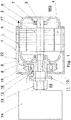
- Fig. 1 shows an air-cooled electric machine 1 of the subject type in partially cut form.
- the electric machine 1 shows a rotatably connected to a rotor shaft 2 rotor 3, a stator 4 arranged therein with axial cooling channels 5 and arranged on the drive side AS bearing plate 8 with a bearing 6 therein for rotatably receiving the rotor shaft 2 and one on the non-drive side NAS of the machine 1 arranged bearing plate 9 with the bearing 7 for rotatably receiving the rotor shaft 2.
- a clutch 11 is provided for connection to a corresponding gear 14.
- the clutch 11 includes a machine-side coupling part 12 and a transmission-side coupling part 13, which are connected to each other, for example via corresponding teeth, such as in a curved-tooth coupling, detachably.
- a fan 15 for guiding the cooling air L through the axial cooling channels 5 is connected.
- the fan 15 is arranged on the drive side AS of the machine 1 and integrated in the coupling 11.
- the cooling air L passes through the air inlets 16 on the drive side AS of the electric machine 1 through the axial cooling channels 5 in the stator 4 to corresponding air outlets 17 on the non-drive side NAS of the electric machine 1.
- the axial Length of the electric machine 1 is not increased by the fan 15, which is why smaller electric machines 1 can be made at the same power or identical electric machines 1 with higher performance over conventional electric machines 1.
- the fan 15 can be arranged on the machine-side coupling part 12, for example, be pressed.
- the area of the fan 15 may be surrounded by a housing 22, whereby the area of the fan 15 is protected from contamination.
- mechanical or magnetic filters can be arranged at the air inlets, which remove particles from the cooling air and prevent deposits in the cooling channels of the electric machine 1.
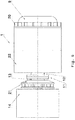
- Fig. 2 shows a variant in which the fan 15 is arranged via corresponding screws 18 on the machine-side coupling part 12. Furthermore, the fan 15, a groove 26 for the Use of balancing weights.
- the fan 15 is preferably formed of steel or aluminum or an aluminum alloy and is possibly produced together with the machine-side coupling part 12, preferably by casting.
- Fig. 4 shows a part of an air-cooled electric machine 1 in a sectional view, wherein elements 19 for guiding the cooling air L in the region of the air inlet 16 and on the inside of the housing 22 are arranged.
- the guide elements 19 are made in one piece with the housing or drive-side end plate 8.
- a further fan 21 is arranged for cooling the transmission 14 on the transmission-side coupling part 13.
- This further fan 21 can in turn be pressed onto the transmission-side coupling part 13 or connected by appropriate screws (not shown).
- cooling fins 20 may be provided to improve the cooling effect.
- FIG. 6 and 7 show a further embodiment of an electric machine 1, wherein on the housing 22 in the region of the axial cooling channels 5 of the stator 4 additional cooling fins 23 are arranged. These cooling ribs 23 are preferably produced in a casting process with the housing 22 of the electric machine 1.
- Fig. 8 shows a further embodiment of an inventively designed air-cooled electric machine 1 with two drive side AS arranged fans 15, 21.
- the blades 25 of the other fan 21 are curved, which is advantageous for electrical machines 1 with only one direction of rotation.
- FIG. 10 a further embodiment of a portion of an electric machine 1 in the sectional view, in which on the drive side AS between the drive-side bearing plate 8 and the rotor shaft 2 and the motor-side coupling part 12, a labyrinth seal 25 is arranged.
- the bearing 6 With the help of the machine-side coupling part 12, the bearing 6 is axially fixed on the drive side AS and prevents turning of the bearing inner ring.
Landscapes
- Engineering & Computer Science (AREA)
- Power Engineering (AREA)
- General Engineering & Computer Science (AREA)
- Mechanical Engineering (AREA)
- Motor Or Generator Cooling System (AREA)
- Motor Or Generator Frames (AREA)
Priority Applications (1)
| Application Number | Priority Date | Filing Date | Title |
|---|---|---|---|
| PL17153168T PL3200327T3 (pl) | 2016-01-29 | 2017-01-26 | Chłodzona powietrzem maszyna elektryczna |
Applications Claiming Priority (1)
| Application Number | Priority Date | Filing Date | Title |
|---|---|---|---|
| ATA50051/2016A AT518218B1 (de) | 2016-01-29 | 2016-01-29 | Luftgekühlte elektrische Maschine |
Publications (2)
| Publication Number | Publication Date |
|---|---|
| EP3200327A1 true EP3200327A1 (fr) | 2017-08-02 |
| EP3200327B1 EP3200327B1 (fr) | 2020-06-03 |
Family
ID=57906516
Family Applications (1)
| Application Number | Title | Priority Date | Filing Date |
|---|---|---|---|
| EP17153168.4A Active EP3200327B1 (fr) | 2016-01-29 | 2017-01-26 | Machine électrique refroidie par air |
Country Status (4)
| Country | Link |
|---|---|
| EP (1) | EP3200327B1 (fr) |
| AT (1) | AT518218B1 (fr) |
| ES (1) | ES2809102T3 (fr) |
| PL (1) | PL3200327T3 (fr) |
Cited By (3)
| Publication number | Priority date | Publication date | Assignee | Title |
|---|---|---|---|---|
| CN111740544A (zh) * | 2020-08-25 | 2020-10-02 | 南京莉上网络科技有限公司 | 一种能够进行热量调节的散热电机 |
| WO2021114451A1 (fr) * | 2019-12-09 | 2021-06-17 | 深圳市中悦机电科技有限公司 | Structure de dissipation de chaleur de moteur à aimant permanent |
| CN114645909A (zh) * | 2022-04-14 | 2022-06-21 | 深圳市联兆电子有限公司 | 一种新能源汽车动力联轴器过温保护装置 |
Citations (5)
| Publication number | Priority date | Publication date | Assignee | Title |
|---|---|---|---|---|
| AT154719B (de) * | 1936-05-28 | 1938-10-25 | Bbc Ag Oesterr | Antrieb für elektrisch betriebene Fahrzeuge, insbesondere für Schienenfahrzeuge leichter Bauart und Straßenfahrzeuge. |
| CH444949A (de) * | 1965-11-09 | 1967-10-15 | Bosch Gmbh Robert | Mit Wechselstrom betreibbarer Kollektormotor |
| US3622821A (en) * | 1970-03-27 | 1971-11-23 | Black & Decker Mfg Co | Double-insulated motor armature |
| DE2548058A1 (de) * | 1975-10-27 | 1977-04-28 | Thyssen Industrie | Doppelachsantrieb fuer schienenfahrzeuge |
| US20040150270A1 (en) * | 2002-11-25 | 2004-08-05 | Takashi Nagayama | Fully enclosed type motor with outer fans |
Family Cites Families (3)
| Publication number | Priority date | Publication date | Assignee | Title |
|---|---|---|---|---|
| US6695581B2 (en) * | 2001-12-19 | 2004-02-24 | Mcmillan Electric Company | Combination fan-flywheel-pulley assembly and method of forming |
| US7459817B2 (en) * | 2006-08-15 | 2008-12-02 | Bombardier Transportation Gmbh | Semi-enclosed AC motor |
| DE102008023712A1 (de) * | 2008-05-15 | 2009-11-19 | Bayerische Motoren Werke Aktiengesellschaft | Antriebsstrang für Hybridfahrzeuge |
-
2016
- 2016-01-29 AT ATA50051/2016A patent/AT518218B1/de active
-
2017
- 2017-01-26 EP EP17153168.4A patent/EP3200327B1/fr active Active
- 2017-01-26 PL PL17153168T patent/PL3200327T3/pl unknown
- 2017-01-26 ES ES17153168T patent/ES2809102T3/es active Active
Patent Citations (5)
| Publication number | Priority date | Publication date | Assignee | Title |
|---|---|---|---|---|
| AT154719B (de) * | 1936-05-28 | 1938-10-25 | Bbc Ag Oesterr | Antrieb für elektrisch betriebene Fahrzeuge, insbesondere für Schienenfahrzeuge leichter Bauart und Straßenfahrzeuge. |
| CH444949A (de) * | 1965-11-09 | 1967-10-15 | Bosch Gmbh Robert | Mit Wechselstrom betreibbarer Kollektormotor |
| US3622821A (en) * | 1970-03-27 | 1971-11-23 | Black & Decker Mfg Co | Double-insulated motor armature |
| DE2548058A1 (de) * | 1975-10-27 | 1977-04-28 | Thyssen Industrie | Doppelachsantrieb fuer schienenfahrzeuge |
| US20040150270A1 (en) * | 2002-11-25 | 2004-08-05 | Takashi Nagayama | Fully enclosed type motor with outer fans |
Cited By (5)
| Publication number | Priority date | Publication date | Assignee | Title |
|---|---|---|---|---|
| WO2021114451A1 (fr) * | 2019-12-09 | 2021-06-17 | 深圳市中悦机电科技有限公司 | Structure de dissipation de chaleur de moteur à aimant permanent |
| CN111740544A (zh) * | 2020-08-25 | 2020-10-02 | 南京莉上网络科技有限公司 | 一种能够进行热量调节的散热电机 |
| CN111740544B (zh) * | 2020-08-25 | 2021-01-22 | 浙江福霸机电有限公司 | 一种能够进行热量调节的散热电机 |
| CN114645909A (zh) * | 2022-04-14 | 2022-06-21 | 深圳市联兆电子有限公司 | 一种新能源汽车动力联轴器过温保护装置 |
| CN114645909B (zh) * | 2022-04-14 | 2023-11-03 | 深圳市联兆电子有限公司 | 一种新能源汽车动力联轴器过温保护装置 |
Also Published As
| Publication number | Publication date |
|---|---|
| AT518218A1 (de) | 2017-08-15 |
| PL3200327T3 (pl) | 2020-11-16 |
| AT518218B1 (de) | 2017-12-15 |
| EP3200327B1 (fr) | 2020-06-03 |
| ES2809102T3 (es) | 2021-03-03 |
Similar Documents
| Publication | Publication Date | Title |
|---|---|---|
| EP3878080B1 (fr) | Machine électrique munie d'un dispositif de refroidissement par fluide | |
| EP2109207B1 (fr) | Machine électrique refroidi par un liquide et procédé correspondant | |
| DE102015011863B4 (de) | Elektrische Maschine | |
| DE112014002014B4 (de) | Hybridmodul für Kraftfahrzeug | |
| DE102016210930B4 (de) | Elektrische Maschine | |
| DE102020106341A1 (de) | Elektrische Maschine | |
| DE102010008584A1 (de) | Elektrische Antriebseinheit | |
| EP1703618B1 (fr) | Moteur électrique à refroidissement par air | |
| EP2191940A1 (fr) | Outil électrique | |
| DE112012000043T5 (de) | Generatormotor | |
| EP0688090B1 (fr) | Système de refroidissement pour un moteur | |
| DE102013020324A1 (de) | Elektrische Maschine, insbesondere Asynchronmaschine | |
| EP3200327B1 (fr) | Machine électrique refroidie par air | |
| EP3584910B1 (fr) | Machine électrique à dissipation de la chaleur perdue améliorée | |
| DE102016004936B4 (de) | Elektrische Maschine | |
| EP2086091A2 (fr) | Machine électrique refroidie par air | |
| DE102011087273B4 (de) | Elektrische Maschine | |
| EP3355444B1 (fr) | Rotor de machine électrique, machine électrique, en particulier machine asynchrone, pour un véhicule automobile et véhicule automobile | |
| DE102021204589A1 (de) | Rotorträger für eine elektrische Maschine sowie elektrische Maschine mit diesem | |
| DE102016215089A1 (de) | Elektrische Maschineneinheit mit einer einem Luftstrom ausgesetzten Schleifringanordnung | |
| EP3211761B1 (fr) | Moteur électrique refroidi par air | |
| DE102013203911B3 (de) | 1Elektrische Maschine mit Frischluftkühlung der Abluftseite | |
| WO2015197158A1 (fr) | Entraînement | |
| DE102019207326A1 (de) | Kühlanordnung für den Rotor einer elektrischen Maschine und elektrische Maschine | |
| DE102024100891A1 (de) | Ventilatorringscheibe für einen Rotor einer elektrischen Maschine, Rotor mit einer solchen Ventilatorringscheibe, elektrische Maschine und Kraftfahrzeug |
Legal Events
| Date | Code | Title | Description |
|---|---|---|---|
| PUAI | Public reference made under article 153(3) epc to a published international application that has entered the european phase |
Free format text: ORIGINAL CODE: 0009012 |
|
| STAA | Information on the status of an ep patent application or granted ep patent |
Free format text: STATUS: THE APPLICATION HAS BEEN PUBLISHED |
|
| AK | Designated contracting states |
Kind code of ref document: A1 Designated state(s): AL AT BE BG CH CY CZ DE DK EE ES FI FR GB GR HR HU IE IS IT LI LT LU LV MC MK MT NL NO PL PT RO RS SE SI SK SM TR |
|
| AX | Request for extension of the european patent |
Extension state: BA ME |
|
| STAA | Information on the status of an ep patent application or granted ep patent |
Free format text: STATUS: REQUEST FOR EXAMINATION WAS MADE |
|
| 17P | Request for examination filed |
Effective date: 20180122 |
|
| RBV | Designated contracting states (corrected) |
Designated state(s): AL AT BE BG CH CY CZ DE DK EE ES FI FR GB GR HR HU IE IS IT LI LT LU LV MC MK MT NL NO PL PT RO RS SE SI SK SM TR |
|
| STAA | Information on the status of an ep patent application or granted ep patent |
Free format text: STATUS: EXAMINATION IS IN PROGRESS |
|
| 17Q | First examination report despatched |
Effective date: 20180411 |
|
| GRAP | Despatch of communication of intention to grant a patent |
Free format text: ORIGINAL CODE: EPIDOSNIGR1 |
|
| STAA | Information on the status of an ep patent application or granted ep patent |
Free format text: STATUS: GRANT OF PATENT IS INTENDED |
|
| RIC1 | Information provided on ipc code assigned before grant |
Ipc: H02K 7/116 20060101ALN20191213BHEP Ipc: F16D 13/76 20060101ALN20191213BHEP Ipc: H02K 1/20 20060101ALN20191213BHEP Ipc: H02K 9/06 20060101ALI20191213BHEP Ipc: B61C 9/48 20060101ALN20191213BHEP Ipc: H02K 9/16 20060101ALI20191213BHEP Ipc: F16D 3/18 20060101ALI20191213BHEP Ipc: H02K 7/00 20060101AFI20191213BHEP |
|
| INTG | Intention to grant announced |
Effective date: 20200117 |
|
| GRAS | Grant fee paid |
Free format text: ORIGINAL CODE: EPIDOSNIGR3 |
|
| GRAA | (expected) grant |
Free format text: ORIGINAL CODE: 0009210 |
|
| STAA | Information on the status of an ep patent application or granted ep patent |
Free format text: STATUS: THE PATENT HAS BEEN GRANTED |
|
| AK | Designated contracting states |
Kind code of ref document: B1 Designated state(s): AL AT BE BG CH CY CZ DE DK EE ES FI FR GB GR HR HU IE IS IT LI LT LU LV MC MK MT NL NO PL PT RO RS SE SI SK SM TR |
|
| REG | Reference to a national code |
Ref country code: GB Ref legal event code: FG4D Free format text: NOT ENGLISH |
|
| REG | Reference to a national code |
Ref country code: AT Ref legal event code: REF Ref document number: 1278045 Country of ref document: AT Kind code of ref document: T Effective date: 20200615 Ref country code: CH Ref legal event code: EP |
|
| REG | Reference to a national code |
Ref country code: DE Ref legal event code: R096 Ref document number: 502017005503 Country of ref document: DE |
|
| REG | Reference to a national code |
Ref country code: CH Ref legal event code: NV Representative=s name: KELLER AND PARTNER PATENTANWAELTE AG, CH |
|
| REG | Reference to a national code |
Ref country code: SE Ref legal event code: TRGR |
|
| REG | Reference to a national code |
Ref country code: CH Ref legal event code: PFA Owner name: TRAKTIONSSYSTEME AUSTRIA GMBH, AT Free format text: FORMER OWNER: TRAKTIONSSYSTEME AUSTRIA GMBH, AT |
|
| REG | Reference to a national code |
Ref country code: LT Ref legal event code: MG4D |
|
| PG25 | Lapsed in a contracting state [announced via postgrant information from national office to epo] |
Ref country code: NO Free format text: LAPSE BECAUSE OF FAILURE TO SUBMIT A TRANSLATION OF THE DESCRIPTION OR TO PAY THE FEE WITHIN THE PRESCRIBED TIME-LIMIT Effective date: 20200903 Ref country code: GR Free format text: LAPSE BECAUSE OF FAILURE TO SUBMIT A TRANSLATION OF THE DESCRIPTION OR TO PAY THE FEE WITHIN THE PRESCRIBED TIME-LIMIT Effective date: 20200904 Ref country code: FI Free format text: LAPSE BECAUSE OF FAILURE TO SUBMIT A TRANSLATION OF THE DESCRIPTION OR TO PAY THE FEE WITHIN THE PRESCRIBED TIME-LIMIT Effective date: 20200603 Ref country code: LT Free format text: LAPSE BECAUSE OF FAILURE TO SUBMIT A TRANSLATION OF THE DESCRIPTION OR TO PAY THE FEE WITHIN THE PRESCRIBED TIME-LIMIT Effective date: 20200603 |
|
| REG | Reference to a national code |
Ref country code: NL Ref legal event code: MP Effective date: 20200603 |
|
| PG25 | Lapsed in a contracting state [announced via postgrant information from national office to epo] |
Ref country code: LV Free format text: LAPSE BECAUSE OF FAILURE TO SUBMIT A TRANSLATION OF THE DESCRIPTION OR TO PAY THE FEE WITHIN THE PRESCRIBED TIME-LIMIT Effective date: 20200603 Ref country code: BG Free format text: LAPSE BECAUSE OF FAILURE TO SUBMIT A TRANSLATION OF THE DESCRIPTION OR TO PAY THE FEE WITHIN THE PRESCRIBED TIME-LIMIT Effective date: 20200903 Ref country code: RS Free format text: LAPSE BECAUSE OF FAILURE TO SUBMIT A TRANSLATION OF THE DESCRIPTION OR TO PAY THE FEE WITHIN THE PRESCRIBED TIME-LIMIT Effective date: 20200603 Ref country code: HR Free format text: LAPSE BECAUSE OF FAILURE TO SUBMIT A TRANSLATION OF THE DESCRIPTION OR TO PAY THE FEE WITHIN THE PRESCRIBED TIME-LIMIT Effective date: 20200603 |
|
| PG25 | Lapsed in a contracting state [announced via postgrant information from national office to epo] |
Ref country code: NL Free format text: LAPSE BECAUSE OF FAILURE TO SUBMIT A TRANSLATION OF THE DESCRIPTION OR TO PAY THE FEE WITHIN THE PRESCRIBED TIME-LIMIT Effective date: 20200603 Ref country code: AL Free format text: LAPSE BECAUSE OF FAILURE TO SUBMIT A TRANSLATION OF THE DESCRIPTION OR TO PAY THE FEE WITHIN THE PRESCRIBED TIME-LIMIT Effective date: 20200603 |
|
| PG25 | Lapsed in a contracting state [announced via postgrant information from national office to epo] |
Ref country code: PT Free format text: LAPSE BECAUSE OF FAILURE TO SUBMIT A TRANSLATION OF THE DESCRIPTION OR TO PAY THE FEE WITHIN THE PRESCRIBED TIME-LIMIT Effective date: 20201006 Ref country code: SM Free format text: LAPSE BECAUSE OF FAILURE TO SUBMIT A TRANSLATION OF THE DESCRIPTION OR TO PAY THE FEE WITHIN THE PRESCRIBED TIME-LIMIT Effective date: 20200603 Ref country code: EE Free format text: LAPSE BECAUSE OF FAILURE TO SUBMIT A TRANSLATION OF THE DESCRIPTION OR TO PAY THE FEE WITHIN THE PRESCRIBED TIME-LIMIT Effective date: 20200603 Ref country code: RO Free format text: LAPSE BECAUSE OF FAILURE TO SUBMIT A TRANSLATION OF THE DESCRIPTION OR TO PAY THE FEE WITHIN THE PRESCRIBED TIME-LIMIT Effective date: 20200603 |
|
| PG25 | Lapsed in a contracting state [announced via postgrant information from national office to epo] |
Ref country code: IS Free format text: LAPSE BECAUSE OF FAILURE TO SUBMIT A TRANSLATION OF THE DESCRIPTION OR TO PAY THE FEE WITHIN THE PRESCRIBED TIME-LIMIT Effective date: 20201003 Ref country code: SK Free format text: LAPSE BECAUSE OF FAILURE TO SUBMIT A TRANSLATION OF THE DESCRIPTION OR TO PAY THE FEE WITHIN THE PRESCRIBED TIME-LIMIT Effective date: 20200603 |
|
| REG | Reference to a national code |
Ref country code: ES Ref legal event code: FG2A Ref document number: 2809102 Country of ref document: ES Kind code of ref document: T3 Effective date: 20210303 |
|
| REG | Reference to a national code |
Ref country code: DE Ref legal event code: R097 Ref document number: 502017005503 Country of ref document: DE |
|
| PLBE | No opposition filed within time limit |
Free format text: ORIGINAL CODE: 0009261 |
|
| STAA | Information on the status of an ep patent application or granted ep patent |
Free format text: STATUS: NO OPPOSITION FILED WITHIN TIME LIMIT |
|
| PG25 | Lapsed in a contracting state [announced via postgrant information from national office to epo] |
Ref country code: DK Free format text: LAPSE BECAUSE OF FAILURE TO SUBMIT A TRANSLATION OF THE DESCRIPTION OR TO PAY THE FEE WITHIN THE PRESCRIBED TIME-LIMIT Effective date: 20200603 |
|
| 26N | No opposition filed |
Effective date: 20210304 |
|
| PG25 | Lapsed in a contracting state [announced via postgrant information from national office to epo] |
Ref country code: SI Free format text: LAPSE BECAUSE OF FAILURE TO SUBMIT A TRANSLATION OF THE DESCRIPTION OR TO PAY THE FEE WITHIN THE PRESCRIBED TIME-LIMIT Effective date: 20200603 |
|
| PG25 | Lapsed in a contracting state [announced via postgrant information from national office to epo] |
Ref country code: MC Free format text: LAPSE BECAUSE OF FAILURE TO SUBMIT A TRANSLATION OF THE DESCRIPTION OR TO PAY THE FEE WITHIN THE PRESCRIBED TIME-LIMIT Effective date: 20200603 |
|
| PG25 | Lapsed in a contracting state [announced via postgrant information from national office to epo] |
Ref country code: LU Free format text: LAPSE BECAUSE OF NON-PAYMENT OF DUE FEES Effective date: 20210126 |
|
| REG | Reference to a national code |
Ref country code: BE Ref legal event code: MM Effective date: 20210131 |
|
| PG25 | Lapsed in a contracting state [announced via postgrant information from national office to epo] |
Ref country code: IE Free format text: LAPSE BECAUSE OF NON-PAYMENT OF DUE FEES Effective date: 20210126 |
|
| PGFP | Annual fee paid to national office [announced via postgrant information from national office to epo] |
Ref country code: SE Payment date: 20220125 Year of fee payment: 6 Ref country code: CZ Payment date: 20220118 Year of fee payment: 6 |
|
| PG25 | Lapsed in a contracting state [announced via postgrant information from national office to epo] |
Ref country code: BE Free format text: LAPSE BECAUSE OF NON-PAYMENT OF DUE FEES Effective date: 20210131 |
|
| REG | Reference to a national code |
Ref country code: AT Ref legal event code: MM01 Ref document number: 1278045 Country of ref document: AT Kind code of ref document: T Effective date: 20220126 |
|
| PG25 | Lapsed in a contracting state [announced via postgrant information from national office to epo] |
Ref country code: AT Free format text: LAPSE BECAUSE OF NON-PAYMENT OF DUE FEES Effective date: 20220126 |
|
| PG25 | Lapsed in a contracting state [announced via postgrant information from national office to epo] |
Ref country code: HU Free format text: LAPSE BECAUSE OF FAILURE TO SUBMIT A TRANSLATION OF THE DESCRIPTION OR TO PAY THE FEE WITHIN THE PRESCRIBED TIME-LIMIT; INVALID AB INITIO Effective date: 20170126 |
|
| P01 | Opt-out of the competence of the unified patent court (upc) registered |
Effective date: 20230522 |
|
| PG25 | Lapsed in a contracting state [announced via postgrant information from national office to epo] |
Ref country code: CY Free format text: LAPSE BECAUSE OF FAILURE TO SUBMIT A TRANSLATION OF THE DESCRIPTION OR TO PAY THE FEE WITHIN THE PRESCRIBED TIME-LIMIT Effective date: 20200603 |
|
| REG | Reference to a national code |
Ref country code: SE Ref legal event code: EUG |
|
| PG25 | Lapsed in a contracting state [announced via postgrant information from national office to epo] |
Ref country code: SE Free format text: LAPSE BECAUSE OF NON-PAYMENT OF DUE FEES Effective date: 20230127 Ref country code: CZ Free format text: LAPSE BECAUSE OF NON-PAYMENT OF DUE FEES Effective date: 20230126 |
|
| PG25 | Lapsed in a contracting state [announced via postgrant information from national office to epo] |
Ref country code: MK Free format text: LAPSE BECAUSE OF FAILURE TO SUBMIT A TRANSLATION OF THE DESCRIPTION OR TO PAY THE FEE WITHIN THE PRESCRIBED TIME-LIMIT Effective date: 20200603 |
|
| PG25 | Lapsed in a contracting state [announced via postgrant information from national office to epo] |
Ref country code: MT Free format text: LAPSE BECAUSE OF FAILURE TO SUBMIT A TRANSLATION OF THE DESCRIPTION OR TO PAY THE FEE WITHIN THE PRESCRIBED TIME-LIMIT Effective date: 20200603 |
|
| PGFP | Annual fee paid to national office [announced via postgrant information from national office to epo] |
Ref country code: PL Payment date: 20241218 Year of fee payment: 9 |
|
| PGFP | Annual fee paid to national office [announced via postgrant information from national office to epo] |
Ref country code: ES Payment date: 20250214 Year of fee payment: 9 |
|
| PGFP | Annual fee paid to national office [announced via postgrant information from national office to epo] |
Ref country code: CH Payment date: 20250201 Year of fee payment: 9 |
|
| PGFP | Annual fee paid to national office [announced via postgrant information from national office to epo] |
Ref country code: FR Payment date: 20250122 Year of fee payment: 9 |
|
| PGFP | Annual fee paid to national office [announced via postgrant information from national office to epo] |
Ref country code: GB Payment date: 20250123 Year of fee payment: 9 Ref country code: IT Payment date: 20250131 Year of fee payment: 9 |
|
| PG25 | Lapsed in a contracting state [announced via postgrant information from national office to epo] |
Ref country code: TR Free format text: LAPSE BECAUSE OF FAILURE TO SUBMIT A TRANSLATION OF THE DESCRIPTION OR TO PAY THE FEE WITHIN THE PRESCRIBED TIME-LIMIT Effective date: 20200603 |
|
| PGFP | Annual fee paid to national office [announced via postgrant information from national office to epo] |
Ref country code: DE Payment date: 20260120 Year of fee payment: 10 |