EP3200411B1 - Égalisation de liaisons à grande vitesse par l'intermédiaire de l'estimation de canal in situ - Google Patents
Égalisation de liaisons à grande vitesse par l'intermédiaire de l'estimation de canal in situ Download PDFInfo
- Publication number
- EP3200411B1 EP3200411B1 EP17152471.3A EP17152471A EP3200411B1 EP 3200411 B1 EP3200411 B1 EP 3200411B1 EP 17152471 A EP17152471 A EP 17152471A EP 3200411 B1 EP3200411 B1 EP 3200411B1
- Authority
- EP
- European Patent Office
- Prior art keywords
- cursor
- settings
- post
- estimating
- performance metric
- Prior art date
- Legal status (The legal status is an assumption and is not a legal conclusion. Google has not performed a legal analysis and makes no representation as to the accuracy of the status listed.)
- Active
Links
Images


Classifications
-
- H—ELECTRICITY
- H04—ELECTRIC COMMUNICATION TECHNIQUE
- H04L—TRANSMISSION OF DIGITAL INFORMATION, e.g. TELEGRAPHIC COMMUNICATION
- H04L25/00—Baseband systems
- H04L25/02—Details ; arrangements for supplying electrical power along data transmission lines
- H04L25/03—Shaping networks in transmitter or receiver, e.g. adaptive shaping networks
- H04L25/03006—Arrangements for removing intersymbol interference
- H04L25/03012—Arrangements for removing intersymbol interference operating in the time domain
- H04L25/03019—Arrangements for removing intersymbol interference operating in the time domain adaptive, i.e. capable of adjustment during data reception
-
- H—ELECTRICITY
- H04—ELECTRIC COMMUNICATION TECHNIQUE
- H04L—TRANSMISSION OF DIGITAL INFORMATION, e.g. TELEGRAPHIC COMMUNICATION
- H04L25/00—Baseband systems
- H04L25/02—Details ; arrangements for supplying electrical power along data transmission lines
- H04L25/0202—Channel estimation
- H04L25/0212—Channel estimation of impulse response
-
- H—ELECTRICITY
- H04—ELECTRIC COMMUNICATION TECHNIQUE
- H04L—TRANSMISSION OF DIGITAL INFORMATION, e.g. TELEGRAPHIC COMMUNICATION
- H04L25/00—Baseband systems
- H04L25/02—Details ; arrangements for supplying electrical power along data transmission lines
- H04L25/03—Shaping networks in transmitter or receiver, e.g. adaptive shaping networks
- H04L25/03006—Arrangements for removing intersymbol interference
- H04L25/03012—Arrangements for removing intersymbol interference operating in the time domain
- H04L25/03019—Arrangements for removing intersymbol interference operating in the time domain adaptive, i.e. capable of adjustment during data reception
- H04L25/03038—Arrangements for removing intersymbol interference operating in the time domain adaptive, i.e. capable of adjustment during data reception with a non-recursive structure
-
- H—ELECTRICITY
- H04—ELECTRIC COMMUNICATION TECHNIQUE
- H04L—TRANSMISSION OF DIGITAL INFORMATION, e.g. TELEGRAPHIC COMMUNICATION
- H04L25/00—Baseband systems
- H04L25/02—Details ; arrangements for supplying electrical power along data transmission lines
- H04L25/03—Shaping networks in transmitter or receiver, e.g. adaptive shaping networks
- H04L25/03006—Arrangements for removing intersymbol interference
- H04L25/03012—Arrangements for removing intersymbol interference operating in the time domain
- H04L25/03019—Arrangements for removing intersymbol interference operating in the time domain adaptive, i.e. capable of adjustment during data reception
- H04L25/03057—Arrangements for removing intersymbol interference operating in the time domain adaptive, i.e. capable of adjustment during data reception with a recursive structure
-
- H—ELECTRICITY
- H04—ELECTRIC COMMUNICATION TECHNIQUE
- H04L—TRANSMISSION OF DIGITAL INFORMATION, e.g. TELEGRAPHIC COMMUNICATION
- H04L25/00—Baseband systems
- H04L25/02—Details ; arrangements for supplying electrical power along data transmission lines
- H04L25/03—Shaping networks in transmitter or receiver, e.g. adaptive shaping networks
- H04L25/03006—Arrangements for removing intersymbol interference
- H04L25/03178—Arrangements involving sequence estimation techniques
- H04L25/03248—Arrangements for operating in conjunction with other apparatus
- H04L25/03254—Operation with other circuitry for removing intersymbol interference
- H04L25/03267—Operation with other circuitry for removing intersymbol interference with decision feedback equalisers
-
- H—ELECTRICITY
- H04—ELECTRIC COMMUNICATION TECHNIQUE
- H04L—TRANSMISSION OF DIGITAL INFORMATION, e.g. TELEGRAPHIC COMMUNICATION
- H04L25/00—Baseband systems
- H04L25/02—Details ; arrangements for supplying electrical power along data transmission lines
- H04L25/03—Shaping networks in transmitter or receiver, e.g. adaptive shaping networks
- H04L25/03006—Arrangements for removing intersymbol interference
- H04L25/03343—Arrangements at the transmitter end
-
- H—ELECTRICITY
- H04—ELECTRIC COMMUNICATION TECHNIQUE
- H04L—TRANSMISSION OF DIGITAL INFORMATION, e.g. TELEGRAPHIC COMMUNICATION
- H04L25/00—Baseband systems
- H04L25/02—Details ; arrangements for supplying electrical power along data transmission lines
- H04L25/03—Shaping networks in transmitter or receiver, e.g. adaptive shaping networks
- H04L25/03878—Line equalisers; line build-out devices
- H04L25/03885—Line equalisers; line build-out devices adaptive
Definitions
- aspects of embodiments of the present invention are directed toward equalization in high-speed links through in-situ channel estimation.
- An end-to-end channel for such a link includes: a transmitter; a communication medium, such as a fabricated link (e.g., fiber optic cable) or other transmitting medium (e.g., for transmitting radio waves) over which binary data (e.g., 1's and 0's, or +1's and -1's) is transmitted; and a receiver.
- a communication medium such as a fabricated link (e.g., fiber optic cable) or other transmitting medium (e.g., for transmitting radio waves) over which binary data (e.g., 1's and 0's, or +1's and -1's) is transmitted
- a receiver An input stream d (corresponding to a message at the transmitting end) sent from the transmitter over the communication medium and received by the receiver as an output stream d' may or may not be reconstructible at the receiving end to the original message, based on factors such as the amount of inter symbol interference (ISI) introduced by the channel.
- ISI inter symbol interference
- Two ways of handling ISI are (1) using error correcting codes to encode the message (which build redundancy into the input stream d and allow the message to be reconstructed even when some of the ISI introduces errors into the output stream d'), and (2) using equalization to reduce the amount of ISI.
- US2016/0006589 A1 presents a method of characterizing a channel between a transmitter and a receiver in a high-speed serial link by determining an overall intersymbol interference probability density function from eye monitor data obtained for the current equalizer setting and extracting a channel ISI PDF from the overall ISI PDF. Subsequently, an overall ISI PDF is generated for different equalizer setting and the extracted channel ISI PDF in order to select the optimal setting for the equalizer.
- the electronic or electric devices and/or any other relevant devices or components according to embodiments of the present invention described herein may be implemented utilizing any suitable hardware, firmware (e.g., an application-specific integrated circuit (ASIC)), software, or a combination of software, firmware, and hardware.
- firmware e.g., an application-specific integrated circuit (ASIC)
- software e.g., software, or a combination of software, firmware, and hardware.
- the various components of these devices may be formed on one integrated circuit (IC) chip or on separate IC chips.
- the various components of these devices may be implemented on a flexible printed circuit film, a tape carrier package (TCP), a printed circuit board (PCB), or formed on one substrate.
- TCP tape carrier package
- PCB printed circuit board
- the various components of these devices may be a process or thread, running on one or more computer processors (such as microprocessors), in one or more computing devices, executing computer program instructions and interacting with other system components for performing the various functionalities described herein.
- the computer program instructions may be stored in a memory that may be implemented in a computing device using a standard memory device such as random access memory (RAM).
- the computer program instructions may also be stored in other, non-transitory, computer readable media such as, for example, a CD-ROM, flash drive, or the like.
- Serial high-speed links and their various components may include a continuous time linear equalizer (CTLE) as part of an analog front end.
- CTLE continuous time linear equalizer
- the CTLE may be part of the receiver and used to cancel part or all of the inter symbol interference (ISI) introduced by the channel.
- ISI inter symbol interference
- the CTLE may have many possible settings, each producing a different output stream profile, and thus may need tuning to reduce or minimize ISI.
- DFE decision feedback equalizer
- the added DFE may further add to the number of settings that affect the output stream profile. Only a small subset (such as one) of these settings may provide for the best link performance, e.g., the link performance that minimizes inter-symbol interference (ISI) and results in a lower error rate for the link than other settings.
- a high-speed serial channel may include chips and other circuits, such as for the receiver. Due to factors such as inconsistencies in the manufacturing process, each chip produced may be subject to small variations that lead to process corners (e.g., some of the chips may perform faster or better, or just differently, than others). Consequently, for example, the CTLE that is integrated into the chip (e.g., a receiver chip) may not account for the process corners, which may vary, for example, across each chip on a wafer or between different production runs. Thus, any default CTLE settings (e.g., for an example CTLE) may be less than optimal for a particular CTLE in a particular receiver. Accordingly, a method of tuning a CTLE to account for non-uniform performance caused by, for example, process corners, may be desired.
- methods of determining improved CTLE settings based on channel tap estimation are described herein. These methods may include the use of a first method for estimating end-to-end channel performance and a second method for adjusting the CTLE settings based on the estimated channel performance. The second method may be further modified according to the presence of a DFE in the receiver. A third method may be used to adjust a transmitter finite impulse response (FIR) by also using the end-to-end channel estimation.
- FIR transmitter finite impulse response
- the end-to-end channel as seen by the receiver may be estimated and a performance metric for the estimated channel may be formed.
- the CTLE settings may then be adjusted and the estimation of the channel and performance metric may be performed again.
- the system (such as a channel optimization system) may iterate through the CTLE settings until an improved or best combination of settings is determined.
- the system may be customized to work with or without a DFE in the receiver.
- the system may work to reduce or minimize a first metric, and in the absence of a DFE, a second metric may be reduced or minimized.
- FIG. 1 is a schematic diagram of an example end-to-end channel system 100 according to an embodiment of the present invention.
- a Serializer/Deserializer (SerDes, "sir-deez”) system 100 is depicted.
- an input stream d (110) is being transmitted by a producer (or transmitting system).
- the resulting output stream d' (190) is being provided to an end system (or receiving system).
- the input stream d may be provided to a transmitter 120 that may serialize and send the stream over a channel 130 to a receiver150.
- noise 140 may be added to the stream.
- the added noise 140 is represented abstractly by an adder between the channel 130 and the receiver 150 that inserts additive white Gaussian noise (AWGN) to the signal.
- AWGN additive white Gaussian noise
- the receiver 150 may include a CTLE 160, a (data) slicer 170, and a DFE 180 with an accompanying adder 185.
- the receiver 150 may output the output stream d' (190) to a receiving system that ultimately consumes the output stream d'.
- the DFE implementation may become more complicated due to the timing constraints in the process technology in which the circuits are implemented.
- the slicer 170 may be doubled or quadrupled to reduce the speed at which each of the slicers 170 operates.
- a technique called unrolled DFE may be used where the first feedback tap is implemented indirectly. All of these different configurations are within the scope of the present invention as the disclosed methods may be applied to any of them.
- FIG. 1 also depicts an example data slicer operation 174, 176, 178 of the slicer 170 and an example eye diagram 172.
- the eye diagram 172 illustrates about three unit intervals of a digital binary signal that takes on two values (e.g., high and low, or about +1 and -1 on the y-axis) and having a unit interval of between 63 and 65 x-axis units (as obtained, for example, by inspection and approximation using the x-axis legend).
- transitions of the binary digital signal between the high and low values are transitions of the binary digital signal between the high and low values (the transitions being about one unit interval in length) and a cursor tap (or center tap or main tap) pulse response h 0 (" h naught") at a little over +1 on the y-axis.
- the cursor pulse response h 0 represents the peak data value at the intended time of signal arrival.
- Another way of expressing this is that the cursor pulse response h 0 is the true data and not noise from other signals intended to be delivered at other times (e.g., at other unit intervals).
- the cursor pulse response h 0 represents the dominant component of a finite impulse response (FIR) filter aligning with the intended signal, and may be a large positive value (corresponding to a high data signal) whose effect is to amplify the intended signal.
- FIR finite impulse response
- other pulse responses such as pre-cursor tap pulse responses h -1 and h -2 corresponding to later signals in the output stream and post-cursor tap pulse responses h 1 and h 2 corresponding to earlier signals in the output stream, may also be used by the FIR filter to cancel interfering effects from signals other than the intended signal.
- the post-cursor and pre-cursor pulse responses may be smaller negative values, whose effects are to attenuate the ISI introduced into the channel from signals other than the intended signal.
- the integer value k (+ or -) in the k -th pulse response h k corresponds to, for example, the number of unit intervals between the cursor pulse response h 0 and the k-th pulse response h k .
- the unit interval is somewhat arbitrary, depending on the application, and in other embodiments, may refer to a fraction (such as a half) or a multiple (such as two) of the period of a repeating (e.g., wavelike) signal.
- the slicer 170 may process the output stream using two operations 174 and 176.
- step 174 data slicer
- the next signal e.g., one unit interval after the previous signal
- the signal e.g., next data signal
- the output stream d' is a binary stream composed of two distinct values, namely 1 and 0.
- the assignment of these distinct values to the binary stream is somewhat arbitrary, e.g., in other embodiments, the values may be +1 and -1, such as with the input stream d 110 and the output stream d' 190.
- step 174 the slicer 170 is comparing for high values, and determines that any positive value of the output signal (such as the output signal having the eye diagram 172) is a high value.
- step 174 data slicer
- step 174 data slicer
- step 176 the next signal in the output stream is further processed by the slicer 170, this time to produce a next error signal.
- the error signal is another binary value (e.g., 0 or 1) used to characterize the output stream.
- the error signal may help characterize the magnitude of the next data signal (such as larger than some value).
- the slicer 170 may compare the next signal to the cursor pulse response h 0 (e.g., a peak data value), and may output a next error signal of 1 if the next signal is greater than the cursor pulse response h 0 and otherwise output the next error signal as 0.
- the slicer 170 may be looking for even higher values than those used to produce the data stream above.
- the slicer 170 may produce an error stream, identifying those data signals exceeding a peak data value.
- the function of the error slicer 176 may be handled by two components, such as one error slicer for positive data and another error slicer for negative data.
- two components such as one error slicer for positive data and another error slicer for negative data.
- steps for processing the error slicer for positive data signals will be described, and it will be understood that one of ordinary skill may adapt these to process the error slicer for the negative data signals instead of or in addition to the positive data signals without departing from the scope of the present invention.
- step 178 adaptation is performed using the data and error signals to produce the pulse response h k .
- FIG. 2 is a flow diagram of an example method 200 of determining improved or optimal CTLE settings of a receiver according to an embodiment of the present invention.
- This and other methods disclosed herein may be implemented, for example, as a series of computer instructions to be executed by a processor (or other computing device), such as a microprocessor, or two or more processors.
- the processor(s) may execute computer program instructions and interact with other system components for performing the various functionalities described herein.
- the computer program instructions may be stored in a memory implemented using a standard memory device, such as, for example, a random access memory (RAM).
- the computer program instructions may also be stored in other non-transitory computer readable media such as, for example, a CD-ROM, flash drive, or the like.
- the methods may also be implemented using hardware circuits (e.g., transistors, capacitors, logic gates, field programmable gate arrays (FPGAs), etc.), or combinations of hardware circuits, software, and firmware, as would be apparent to one of ordinary skill.
- method 200 includes simulating the pulse response of the channel at various uniform time intervals (e.g., pre-cursor, cursor, and post-cursor) under a FIR methodology. It is assumed that a CTLE is being used as a front-end to the receiver.
- the resulting pulse response values e.g., pre-cursor pulse responses h -1 , h -2 , etc.; cursor pulse response h 0 ; and post-cursor pulse responses h 1 , h 2 , etc.
- these pulse response values h k normally decay rapidly with increasing magnitude (positive or negative) of k, so only a few values of h k are usually sufficient to estimate the channel.
- processing begins, and in step 210, an initial pulse response h 0 is calculated (or estimated or adapted) by iterating equations 1, 2, 3, and 4:
- d 0 ( n ) indicates whether the current output signal from the channel is positive or negative
- h 0 ( n ) represents a slowly increasing approximation of the cursor pulse response h 0
- z 0 ( n ) is the difference between the magnitude (e.g., absolute value) of the current output signal and the cursor pulse approximation
- e 0 ( n ) indicates whether this difference is positive or negative. Accordingly, when the magnitude of the current output signal exceeds the current estimate of h 0 , the estimate is incremented slightly and the process repeated. Likewise, when the magnitude of the current output signal falls short of the current estimate of h 0 , the estimate is decremented slightly and the process repeated.
- the channel is sufficiently noisy that errors occur at a rate of about 10 -3 (e.g., about 1 in 1000) with default CTLE settings and without a DFE. Accordingly, if the iteration in step 210 is repeated, for example, several thousand times, and the data stream and error stream have a reasonable number of +1's and -1's, then h 0 ( n ) converges quickly (or its rate of growth slows considerably). Accordingly, the cursor pulse response h 0 may be estimated quickly and accurately using equations 1, 2, 3, and 4.
- the h 0 estimation may be utilized to make further estimations for a plurality uniform time intervals (e.g., for other pulse response values) for the default as well as other CTLE settings.
- the pulse response may be estimated for two preceding uniform time intervals (pre-cursors h -1 and h -2 ) and for 6 to 8 later uniform time intervals (post-cursors h 1 , h 2 , etc.)
- d k ( n ) indicates whether the current output signal y ( n ) from the channel is positive or negative, and coincides with another positive or negative output signal k unit intervals earlier (e.g., y ( n - k )), h k ( n ) represents a slowly decreasing approximation of the post-cursor pulse response h k (assuming the pulse response is a negative value), z k ( n ) is the difference between the magnitude (e.g., absolute value) of the current error and the post-cursor pulse response approximation, and e k ( n ) indicates whether this difference is positive or negative.
- the channel is sufficiently noisy that errors occur at a rate of about 10 -3 (e.g., about 1 in 1000) with default CTLE settings and without a DFE. Accordingly, if the iteration is repeated, for example, several thousand times, and the data stream and error stream have a reasonable number of +1's and -1's, then h k ( n ) converges quickly (or its rate of growth slows considerably). Accordingly, the k-th post-cursor pulse response h k may be estimated quickly and accurately using equations 5, 6, 7, and 8.
- equations 5, 6, 7, and 8 may further be used to estimate the pre-cursor pulse responses (e.g., pre-cursors pulse responses h -1 and h -2 ), only substituting negative integers for k.
- pre-cursor pulse responses e.g., pre-cursors pulse responses h -1 and h -2
- pre-cursor pulse responses ( n - k )-th values of the signals take place after the corresponding n -th values of the signals, since n - k is larger than n for negative values of k.
- the h k estimations for the earlier pulse responses may be utilized to make estimations of the later post-cursor and pre-cursor pulse responses (e.g., further from the cursor tap h 0 ).
- the estimates for h 0 and h 1 may be used to estimate the post-cursor h 2 or the pre-cursor h -1 in a similar fashion to how the h 0 estimate is used to estimate the post-cursor h 1 , as would be apparent to one of ordinary skill in the art.
- a signal to ISI ratio (SIR) metric may then be calculated after the pulse response for each of the time intervals has been determined.
- the SIR metric may be calculated a number of different ways. For example, in one embodiment, SIR may be calculated according to equations 9 or 10 depending on whether a DFE is being used. This embodiment may be selected for systems where minimizing the mean square error is desired.
- SIR no DFE h 0 2 ⁇ i ⁇ 0 h i 2
- SIR DFE h 0 2 ⁇ i ⁇ 0 or i > numDFEtaps h i 2
- numDFEtaps is the number of taps in the DFE and the summations take place over all h i for which estimates are obtained in step 220 (e.g., h -2 , h -1 , h 1 , h 2 , h 3 , h 4 , h 5 , h 6 ) other than those explicitly excluded.
- SIR may be calculated according to equations 9 or 10 depending on whether a DFE is being used.
- SIR no DFE h 0 ⁇ i ⁇ 0 h i
- SIR DFE h 0 ⁇ i ⁇ 0 or i > numDFEtaps h i
- the ISI may have only a single dominant cursor.
- a DFE may be able to handle the ISI at the other taps.
- SIR may be calculated according to equation 11.
- SIR DFE h ⁇ 1
- step 240 once the current (or new) SIR metric has been calculated or otherwise determined, it may be compared to the best (or old) SIR metric. If the new metric is better than the old one, then in step 250, the new metric is saved and the next CTLE setting is tested.
- the CTLE settings may be ordered, the SIR metrics determined based on this ordering, and the default setting may be the first such setting in the ordering. It may be characteristic of the SIR metrics for the CTLE setting ordering that the corresponding SIR metrics are monotonically increasing to a single peak (maximum) and then monotonically decreasing thereafter.
- step 260 if instead the new metric is lower than that of the previous (or old) CTLE setting, then processing may stop, as the peak has been reached by the previous CTLE setting.
- CTLE setting may be in the middle of the ordered CTLE settings
- further CTLE settings may be tested, such as all of the CTLE settings, or those before the default CTLE settings once those after the CTLE setting have had corresponding decreasing SIR metrics.
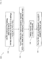
- FIG. 3 is a flow diagram of an example method 300 of determining improved or optimal transmitter (TX) FIR settings according to an embodiment of the present invention.
- transmitter finite impulse response (FIR) settings may also be improved or optimized.
- processing begins, and in step 310, the CTLE settings determined above and the corresponding pulse response estimates may be used in step 320 to determine two metrics of channel frequency response, H(0) and H(Nyquist).
- the channel loss may then be defined as the difference between H(0) and H(Nyquist).
- a Tx FIR transmitter FIR
- H(0) and H(Nyquist) may be calculated according to equations 12 and 13.
- H 0 ⁇ i h i
- H Nyquist ⁇ i ⁇ 1 i h i
- TX FIR look up table is shown below in Table 1. Many variations of the table may be constructed as would be apparent to one of ordinary skill.
- a method to improve or optimize some or all elements of a link (such as a high-speed link in a SerDes system) is provided, and the method may be used to lessen or cancel channel ISI.
- the method may be used for a UDDI (Universal Description, Discovery, and Integration) interface.
- UDDI Universal Description, Discovery, and Integration
- a method to estimate the end-to-end channel using existing hardware that provides sign information only is provided.
- a method of tuning a CTLE based on estimating channel characteristics, such as FIR coefficients is provided. Some of these embodiments include a DFE in the receiver, while others have no DFE in the receiver.
- a method of adjusting a transmitter FIR based on estimating channel characteristics using existing hardware is provided.
Landscapes
- Engineering & Computer Science (AREA)
- Power Engineering (AREA)
- Computer Networks & Wireless Communication (AREA)
- Signal Processing (AREA)
- Dc Digital Transmission (AREA)
Claims (16)
- Procédé pour estimer la performance d'un canal de communication série et accorder un égaliseur linéaire à temps continu, CTLE, en utilisant des circuits de traitement, le canal étant configuré pour transmettre un flux d'entrée binaire à partir d'une extrémité de transmission à un flux de sortie au niveau d'une extrémité de réception, le procédé comprenant l'étape consistant à :
modéliser, par les circuits de traitement, le canal à l'extrémité de réception en tant que premier système à réponse impulsionnelle finie (FIR), où l'extrémité de réception comprend le CTLE, et la modélisation du canal à l'extrémité de réception comprend la modélisation du canal à l'extrémité de réception après le CTLE, la modélisation comprenant en outre :l'estimation d'une réponse impulsionnelle de curseur du premier système FIR en analysant le flux de sortie reçu à l'extrémité de réception ; etl'estimation d'une ou plusieurs réponses impulsionnelles avant curseur ou après curseur du premier système FIR à partir du flux de sortie reçu en utilisant la réponse impulsionnelle de curseur estimée ;le procédé comprenant en outre les étapes consistant à :déterminer, par les circuits de traitement, une métrique de performance en utilisant lesdites une ou plusieurs réponses impulsionnelles avant curseur ou après curseur estimées,et accorder le CTLE en sélectionnant l'un d'une pluralité de réglages conformément à la métrique de performance déterminée, oùle CTLE est configuré pour être accordé en sélectionnant l'un d'une pluralité de réglages comprenant un réglage par défaut, etl'estimation de la réponse impulsionnelle de curseur comprend l'estimation de la réponse impulsionnelle de curseur en utilisant le réglage par défaut. - Procédé selon la revendication 1, dans lequel l'estimation des réponses impulsionnelles de curseur, avant curseur et après curseur comprend uniquement l'utilisation d'opérateurs d'addition, de soustraction, de comparaison, et booléens.
- Procédé selon la revendication 1 ou 2, dans lequel l'estimation des une ou plusieurs réponses impulsionnelles avant curseur ou après curseur comprend l'estimation d'une ou plusieurs des réponses impulsionnelles avant curseur et d'une ou plusieurs des réponses impulsionnelles après curseur.
- Procédé selon la revendication 3, dans lequel l'estimation des une ou plusieurs réponses impulsionnelles avant curseur ou après curseur comprend l'estimation de deux ou plus de deux des réponses impulsionnelles avant curseur et de six ou plus de six des réponses impulsionnelles après curseur.
- Procédé selon l'une quelconque des revendications précédentes, dans lequel
l'estimation des une ou plusieurs réponses impulsionnelles avant curseur ou après curseur comprend l'estimation des une ou plusieurs réponses impulsionnelles avant curseur ou après curseur pour chacun de deux ou plus de deux des réglages ; et
la détermination de la métrique de performance comprend la détermination de la métrique de performance pour chacun des deux ou plus de deux des réglages en utilisant l'une correspondante desdites une ou plusieurs réponses impulsionnelles avant curseur ou après curseur estimées. - Procédé selon la revendication 5, comprenant en outre les étapes consistant à :comparer, par les circuits de traitement, la métrique de performance de l'un des deux ou plus de deux des réglages à la métrique de performance d'un autre des deux ou plus de deux réglages ; etaccorder, par les circuits de traitement, le CTLE en sélectionnant l'un des réglages sur la base de la comparaison.
- Procédé selon la revendication 6, dans lequel les deux ou plus de deux des réglages comprennent tous les réglages.
- Procédé selon la revendication 6 ou 7, dans lequel les réglages sont ordonnés, et l'estimation des une ou plusieurs réponses impulsionnelles avant curseur ou après curseur et la détermination de la métrique de performance comprennent l'arrêt de l'estimation des une ou plusieurs réponses impulsionnelles avant curseur ou après curseur et la détermination de la métrique de performance une fois que la métrique de performance pour un réglage suivant parmi les réglages est plus mauvaise que la métrique de performance pour un réglage précédent parmi les réglages.
- Procédé selon la revendication 6 ou 7, dans lequel l'extrémité de réception comprend en outre un égaliseur à rétroaction de décision (DFE) après le CTLE et la modélisation du canal à l'extrémité de réception comprend en outre la modélisation du canal à l'extrémité de réception après le DFE.
- Procédé selon la revendication 6, 7, 8 ou 9, dans lequel l'extrémité de transmission comprend un deuxième système FIR et le procédé comprend en outre l'étape consistant à ajuster, par les circuits de traitement, le deuxième système FIR sur la base des une ou plusieurs réponses impulsionnelles avant curseur ou après curseur estimées correspondantes du réglage sélectionné parmi les réglages.
- Système pour estimer la performance d'un canal de communication série et pour accorder un égaliseur linéaire à temps continu, CTLE, le canal étant configuré pour transmettre un flux d'entrée binaire à partir d'une extrémité de transmission à un flux de sortie au niveau d'une extrémité de réception, le système comprenant :un support de mémorisation non volatil ; etdes circuits de traitement configurés pour :
modéliser le canal à l'extrémité de réception en tant que premier système de réponse impulsionnelle finie (FIR), où l'extrémité de réception comprend le CTLE, et la modélisation du canal à l'extrémité de réception comprend la modélisation du canal à l'extrémité de réception après le CTLE, la modélisation comprenant en outre :l'estimation d'une réponse impulsionnelle de curseur du premier système FIR en analysant le flux de sortie reçu à l'extrémité de réception ;l'estimation d'une ou plusieurs réponses impulsionnelles avant curseur ou après curseur du premier système FIR à partir du flux de sortie reçu en utilisant la réponse impulsionnelle de curseur estimée ; etla mémorisation des réponses impulsionnelles de curseur, avant curseur, et après curseur estimées sur le support de mémorisation non volatil ;le support de mémorisation non volatil et les circuits de traitement étant en outre configurés pour :déterminer une métrique de performance en utilisant les une ou plusieurs réponses impulsionnelles avant curseur ou après curseur estimées ; etmémoriser la métrique de performance sur le support de mémorisation non volatil ;accorder le CTLE en sélectionnant l'un d'une pluralité de réglages conformément à la métrique de performance déterminée, oùle CTLE est configuré pour être accordé en sélectionnant l'un d'une pluralité de réglages comprenant un réglage par défaut, etl'estimation de la réponse impulsionnelle de curseur comprend l'estimation de la réponse impulsionnelle de curseur en utilisant le réglage par défaut. - Système selon la revendication 11, dans lequel l'estimation des une ou plusieurs réponses impulsionnelles avant curseur ou après curseur comprend l'estimation des une ou plusieurs réponses impulsionnelles avant curseur ou après curseur pour chacun de deux ou plus de deux des réglages ; et
la détermination de la métrique de performance comprend la détermination de la métrique de performance pour chacun des deux ou plus de deux des réglages en utilisant l'une correspondante desdites une ou plusieurs réponses impulsionnelles avant curseur ou après curseur estimées. - Système selon la revendication 12, dans lequel les circuits de traitement sont en outre configurés pour :comparer la métrique de performance de l'un des deux ou plus de deux des réglages à la métrique de performance d'un autre des deux ou plus de deux des réglages ;accorder le CTLE en sélectionnant l'un des réglages sur la base de la comparaison ; etmémoriser le réglage sélectionné parmi les réglages sur le support de mémorisation non volatil.
- Système selon la revendication 13, dans lequel les réglages sont ordonnés, et l'estimation des une ou plusieurs réponses impulsionnelles avant curseur ou après curseur et la détermination de la métrique de performance comprennent l'arrêt de l'estimation des une ou plusieurs réponses impulsionnelles avant curseur ou après curseur et la détermination de la métrique de performance une fois que la métrique de performance pour un réglage suivant parmi les réglages est plus mauvaise que la métrique de performance pour un réglage précédent parmi les réglages.
- Système selon la revendication 13 ou 14, dans lequel l'extrémité de réception comprend en outre un égaliseur à rétroaction de décision (DFE) après le CTLE et la modélisation du canal à l'extrémité de réception comprend en outre la modélisation du canal à l'extrémité de réception après le DFE.
- Système selon la revendication 13, 14 ou 15, dans lequel l'extrémité de transmission comprend un deuxième système FIR et les circuits de traitement sont en outre configurés pour ajuster le deuxième système FIR sur la base des une ou plusieurs réponses impulsionnelles avant curseur ou après curseur estimées correspondantes du réglage sélectionné parmi les réglages.
Applications Claiming Priority (2)
| Application Number | Priority Date | Filing Date | Title |
|---|---|---|---|
| US201662288775P | 2016-01-29 | 2016-01-29 | |
| US15/230,222 US9866412B2 (en) | 2016-01-29 | 2016-08-05 | Equalization in high speed links through in-situ channel estimation |
Publications (2)
| Publication Number | Publication Date |
|---|---|
| EP3200411A1 EP3200411A1 (fr) | 2017-08-02 |
| EP3200411B1 true EP3200411B1 (fr) | 2019-07-31 |
Family
ID=57881991
Family Applications (1)
| Application Number | Title | Priority Date | Filing Date |
|---|---|---|---|
| EP17152471.3A Active EP3200411B1 (fr) | 2016-01-29 | 2017-01-20 | Égalisation de liaisons à grande vitesse par l'intermédiaire de l'estimation de canal in situ |
Country Status (4)
| Country | Link |
|---|---|
| US (1) | US9866412B2 (fr) |
| EP (1) | EP3200411B1 (fr) |
| KR (1) | KR20170091509A (fr) |
| CN (1) | CN107026807A (fr) |
Families Citing this family (2)
| Publication number | Priority date | Publication date | Assignee | Title |
|---|---|---|---|---|
| CN107657978B (zh) * | 2017-11-01 | 2018-09-21 | 睿力集成电路有限公司 | 随机存储器 |
| US11005567B2 (en) * | 2019-07-01 | 2021-05-11 | Credo Technology Group Limited | Efficient multi-mode DFE |
Citations (1)
| Publication number | Priority date | Publication date | Assignee | Title |
|---|---|---|---|---|
| WO2016190923A1 (fr) * | 2015-05-27 | 2016-12-01 | Xilinx, Inc. | Récepteur à adc adaptable au canal |
Family Cites Families (29)
| Publication number | Priority date | Publication date | Assignee | Title |
|---|---|---|---|---|
| US5608755A (en) * | 1994-10-14 | 1997-03-04 | Rakib; Selim | Method and apparatus for implementing carrierless amplitude/phase encoding in a network |
| US6563858B1 (en) * | 1998-01-16 | 2003-05-13 | Intersil Americas Inc. | Method of performing antenna diversity in spread spectrum in wireless local area network |
| US6233273B1 (en) * | 1999-06-29 | 2001-05-15 | Intersil Americas Inc. | Rake receiver with embedded decision feedback equalizer |
| WO2006056048A1 (fr) | 2004-11-23 | 2006-06-01 | Diablo Technologies Inc. | Egaliseur adaptatif fonde sur un recepteur assurant une compensation de brouillage entre symboles pre-curseur |
| WO2008070138A2 (fr) * | 2006-12-05 | 2008-06-12 | Rambus Inc. | Procédés et circuits pour une distribution asymétrique d'égalisation de canaux entre des dispositifs |
| US8213494B2 (en) | 2008-06-20 | 2012-07-03 | Fujitsu Limited | Sign-based general zero-forcing adaptive equalizer control |
| US8837626B2 (en) | 2011-12-09 | 2014-09-16 | Lsi Corporation | Conditional adaptation of linear filters in a system having nonlinearity |
| US20150256364A1 (en) * | 2008-11-25 | 2015-09-10 | Lsi Corporation | Group delay based back channel post cursor adaptation |
| US8379711B2 (en) | 2009-06-30 | 2013-02-19 | Lsi Corporation | Methods and apparatus for decision-feedback equalization with oversampled phase detector |
| US8731040B2 (en) * | 2010-09-28 | 2014-05-20 | Lsi Corporation | Adapting transfer functions of continuous-time equalizers |
| US8705672B2 (en) | 2011-09-26 | 2014-04-22 | Lsi Corporation | Method of compensating for nonlinearity in a DFE-based receiver |
| US8743945B2 (en) * | 2012-03-02 | 2014-06-03 | Lsi Corporation | Shift register based downsampled floating tap decision feedback equalization |
| US9385897B2 (en) * | 2012-07-18 | 2016-07-05 | Avago Technologies General Ip (Singapore) Pte. Ltd. | Methods and apparatus for adapting transmitter equalization coefficients based on receiver gain adaptation |
| US8902964B2 (en) | 2012-09-29 | 2014-12-02 | Intel Corporation | Equalization effort-balancing of transmit finite impulse response and receive linear equalizer or receive decision feedback equalizer structures in high-speed serial interconnects |
| US8861583B2 (en) | 2012-12-14 | 2014-10-14 | Altera Corporation | Apparatus and methods for equalizer adaptation |
| US9052900B2 (en) | 2013-01-29 | 2015-06-09 | Oracle International Corporation | Serdes fast retrain method upon exiting power saving mode |
| US8953665B2 (en) * | 2013-02-15 | 2015-02-10 | Lsi Corporation | Pattern-based loss of signal detector |
| US9143369B2 (en) * | 2013-03-15 | 2015-09-22 | Intel Corporation | Adaptive backchannel equalization |
| US9237044B1 (en) | 2013-05-17 | 2016-01-12 | Altera Corporation | Methods for joint optimization of link equalization |
| US9762381B2 (en) * | 2013-07-03 | 2017-09-12 | Nvidia Corporation | Adaptation of crossing DFE tap weight |
| US9166832B1 (en) | 2013-10-04 | 2015-10-20 | Altera Corporation | Methods and apparatus for decision feedback equalization adaptation |
| US9071477B2 (en) * | 2013-10-09 | 2015-06-30 | Global Unichip Corporation | Method and associated processing module for interconnection system |
| US8958512B1 (en) | 2013-10-18 | 2015-02-17 | Altera Corporation | System and method for receiver equalization adaptation |
| US9325489B2 (en) | 2013-12-19 | 2016-04-26 | Xilinx, Inc. | Data receivers and methods of implementing data receivers in an integrated circuit |
| US9397872B2 (en) | 2014-07-01 | 2016-07-19 | Samsung Display Co., Ltd. | System and method of link optimization |
| US20160065394A1 (en) * | 2014-08-26 | 2016-03-03 | Avago Technologies General Ip (Singapore) Pte. Ltd. | Serializer/deserializer with independent equalization adaptation for reducing even/odd eye disparity |
| US9397824B1 (en) * | 2015-01-28 | 2016-07-19 | Texas Instruments Incorporated | Gear shifting from binary phase detector to PAM phase detector in CDR architecture |
| US9397867B1 (en) * | 2015-02-11 | 2016-07-19 | Applied Micro Circuits Corporation | Clock phase adaptation for precursor ISI reduction |
| US9461851B1 (en) * | 2015-10-16 | 2016-10-04 | Xilinx, Inc. | Circuits for and methods of robust adaptation of a continuous time linear equalizer circuit |
-
2016
- 2016-08-05 US US15/230,222 patent/US9866412B2/en not_active Expired - Fee Related
-
2017
- 2017-01-18 KR KR1020170008570A patent/KR20170091509A/ko not_active Withdrawn
- 2017-01-19 CN CN201710043253.0A patent/CN107026807A/zh active Pending
- 2017-01-20 EP EP17152471.3A patent/EP3200411B1/fr active Active
Patent Citations (1)
| Publication number | Priority date | Publication date | Assignee | Title |
|---|---|---|---|---|
| WO2016190923A1 (fr) * | 2015-05-27 | 2016-12-01 | Xilinx, Inc. | Récepteur à adc adaptable au canal |
Also Published As
| Publication number | Publication date |
|---|---|
| CN107026807A (zh) | 2017-08-08 |
| EP3200411A1 (fr) | 2017-08-02 |
| KR20170091509A (ko) | 2017-08-09 |
| US9866412B2 (en) | 2018-01-09 |
| US20170222840A1 (en) | 2017-08-03 |
Similar Documents
| Publication | Publication Date | Title |
|---|---|---|
| US12316481B2 (en) | Edge based partial response equalization | |
| US9397872B2 (en) | System and method of link optimization | |
| EP1430672B1 (fr) | Calcul rapide de coefficients d egaliseur a decision retroac tive | |
| EP1365554B1 (fr) | Calcul de coefficients pour un égaliseur à rétroaction de décision et à délai variable | |
| US9191244B2 (en) | Equalizer and semiconductor device | |
| US10236892B2 (en) | System and method for maintaining high speed communication | |
| KR20060131883A (ko) | 등화 제어를 위한 보드, 시스템, 방법 및 컴퓨터 판독가능매체 | |
| WO2003026237A2 (fr) | Calcul rapide de coefficients d'egaliseur a decision retroactive mimo | |
| KR20140011286A (ko) | 수신기 이득 적응에 기반한 송신기 등화 계수를 적응하는 방법 및 장치 | |
| US10833895B2 (en) | Receiver with selectable digital equalization filter options | |
| EP3200411B1 (fr) | Égalisation de liaisons à grande vitesse par l'intermédiaire de l'estimation de canal in situ | |
| US8000384B2 (en) | Apparatus for stabilizing convergence of an adaptive line equalizer | |
| Rangel-Patiño et al. | Direct optimization of a PCI Express link equalization in industrial post-silicon validation | |
| US7257155B2 (en) | Method for initialization and stepsize control of time-domain equalizer in multi-carrier communication system | |
| US11811566B2 (en) | Methods and systems for performing adaptive equalization of data | |
| US20160277220A1 (en) | Pattern-based coefficient adaptation operation for decision feedback equalization | |
| Gore et al. | An excerise in applying channel operating margin (COM) for 10GBASE-KR channel design | |
| US8259883B2 (en) | Timing recovery circuit and method thereof | |
| CN116208292B (zh) | 信号处理器优化方法、信号处理器及计算机可读存储介质 | |
| KR100860503B1 (ko) | 계층적 궤환 필터 및 연판정 장치를 이용한 결정 궤환등화기 | |
| Gong et al. | A variable time lag algorithm for the FIR equalizer | |
| García-Alís et al. | Bit true adaptive equalisation design and simulation library | |
| CN104243367A (zh) | 加速等化收敛速度的接收装置与方法 |
Legal Events
| Date | Code | Title | Description |
|---|---|---|---|
| PUAI | Public reference made under article 153(3) epc to a published international application that has entered the european phase |
Free format text: ORIGINAL CODE: 0009012 |
|
| STAA | Information on the status of an ep patent application or granted ep patent |
Free format text: STATUS: THE APPLICATION HAS BEEN PUBLISHED |
|
| AK | Designated contracting states |
Kind code of ref document: A1 Designated state(s): AL AT BE BG CH CY CZ DE DK EE ES FI FR GB GR HR HU IE IS IT LI LT LU LV MC MK MT NL NO PL PT RO RS SE SI SK SM TR |
|
| AX | Request for extension of the european patent |
Extension state: BA ME |
|
| STAA | Information on the status of an ep patent application or granted ep patent |
Free format text: STATUS: REQUEST FOR EXAMINATION WAS MADE |
|
| 17P | Request for examination filed |
Effective date: 20180118 |
|
| RBV | Designated contracting states (corrected) |
Designated state(s): AL AT BE BG CH CY CZ DE DK EE ES FI FR GB GR HR HU IE IS IT LI LT LU LV MC MK MT NL NO PL PT RO RS SE SI SK SM TR |
|
| STAA | Information on the status of an ep patent application or granted ep patent |
Free format text: STATUS: EXAMINATION IS IN PROGRESS |
|
| 17Q | First examination report despatched |
Effective date: 20180605 |
|
| GRAP | Despatch of communication of intention to grant a patent |
Free format text: ORIGINAL CODE: EPIDOSNIGR1 |
|
| STAA | Information on the status of an ep patent application or granted ep patent |
Free format text: STATUS: GRANT OF PATENT IS INTENDED |
|
| INTG | Intention to grant announced |
Effective date: 20190328 |
|
| RAP1 | Party data changed (applicant data changed or rights of an application transferred) |
Owner name: SAMSUNG DISPLAY CO., LTD. |
|
| RIN1 | Information on inventor provided before grant (corrected) |
Inventor name: KAMALI, JALIL Inventor name: MALHOTRA, GAURAV |
|
| GRAS | Grant fee paid |
Free format text: ORIGINAL CODE: EPIDOSNIGR3 |
|
| GRAA | (expected) grant |
Free format text: ORIGINAL CODE: 0009210 |
|
| STAA | Information on the status of an ep patent application or granted ep patent |
Free format text: STATUS: THE PATENT HAS BEEN GRANTED |
|
| AK | Designated contracting states |
Kind code of ref document: B1 Designated state(s): AL AT BE BG CH CY CZ DE DK EE ES FI FR GB GR HR HU IE IS IT LI LT LU LV MC MK MT NL NO PL PT RO RS SE SI SK SM TR |
|
| REG | Reference to a national code |
Ref country code: CH Ref legal event code: EP Ref country code: GB Ref legal event code: FG4D |
|
| REG | Reference to a national code |
Ref country code: AT Ref legal event code: REF Ref document number: 1162188 Country of ref document: AT Kind code of ref document: T Effective date: 20190815 |
|
| REG | Reference to a national code |
Ref country code: IE Ref legal event code: FG4D |
|
| REG | Reference to a national code |
Ref country code: DE Ref legal event code: R096 Ref document number: 602017005592 Country of ref document: DE |
|
| REG | Reference to a national code |
Ref country code: NL Ref legal event code: MP Effective date: 20190731 |
|
| REG | Reference to a national code |
Ref country code: LT Ref legal event code: MG4D |
|
| REG | Reference to a national code |
Ref country code: AT Ref legal event code: MK05 Ref document number: 1162188 Country of ref document: AT Kind code of ref document: T Effective date: 20190731 |
|
| PG25 | Lapsed in a contracting state [announced via postgrant information from national office to epo] |
Ref country code: NO Free format text: LAPSE BECAUSE OF FAILURE TO SUBMIT A TRANSLATION OF THE DESCRIPTION OR TO PAY THE FEE WITHIN THE PRESCRIBED TIME-LIMIT Effective date: 20191031 Ref country code: SE Free format text: LAPSE BECAUSE OF FAILURE TO SUBMIT A TRANSLATION OF THE DESCRIPTION OR TO PAY THE FEE WITHIN THE PRESCRIBED TIME-LIMIT Effective date: 20190731 Ref country code: AT Free format text: LAPSE BECAUSE OF FAILURE TO SUBMIT A TRANSLATION OF THE DESCRIPTION OR TO PAY THE FEE WITHIN THE PRESCRIBED TIME-LIMIT Effective date: 20190731 Ref country code: HR Free format text: LAPSE BECAUSE OF FAILURE TO SUBMIT A TRANSLATION OF THE DESCRIPTION OR TO PAY THE FEE WITHIN THE PRESCRIBED TIME-LIMIT Effective date: 20190731 Ref country code: PT Free format text: LAPSE BECAUSE OF FAILURE TO SUBMIT A TRANSLATION OF THE DESCRIPTION OR TO PAY THE FEE WITHIN THE PRESCRIBED TIME-LIMIT Effective date: 20191202 Ref country code: LT Free format text: LAPSE BECAUSE OF FAILURE TO SUBMIT A TRANSLATION OF THE DESCRIPTION OR TO PAY THE FEE WITHIN THE PRESCRIBED TIME-LIMIT Effective date: 20190731 Ref country code: NL Free format text: LAPSE BECAUSE OF FAILURE TO SUBMIT A TRANSLATION OF THE DESCRIPTION OR TO PAY THE FEE WITHIN THE PRESCRIBED TIME-LIMIT Effective date: 20190731 Ref country code: BG Free format text: LAPSE BECAUSE OF FAILURE TO SUBMIT A TRANSLATION OF THE DESCRIPTION OR TO PAY THE FEE WITHIN THE PRESCRIBED TIME-LIMIT Effective date: 20191031 Ref country code: FI Free format text: LAPSE BECAUSE OF FAILURE TO SUBMIT A TRANSLATION OF THE DESCRIPTION OR TO PAY THE FEE WITHIN THE PRESCRIBED TIME-LIMIT Effective date: 20190731 |
|
| PG25 | Lapsed in a contracting state [announced via postgrant information from national office to epo] |
Ref country code: AL Free format text: LAPSE BECAUSE OF FAILURE TO SUBMIT A TRANSLATION OF THE DESCRIPTION OR TO PAY THE FEE WITHIN THE PRESCRIBED TIME-LIMIT Effective date: 20190731 Ref country code: ES Free format text: LAPSE BECAUSE OF FAILURE TO SUBMIT A TRANSLATION OF THE DESCRIPTION OR TO PAY THE FEE WITHIN THE PRESCRIBED TIME-LIMIT Effective date: 20190731 Ref country code: RS Free format text: LAPSE BECAUSE OF FAILURE TO SUBMIT A TRANSLATION OF THE DESCRIPTION OR TO PAY THE FEE WITHIN THE PRESCRIBED TIME-LIMIT Effective date: 20190731 Ref country code: IS Free format text: LAPSE BECAUSE OF FAILURE TO SUBMIT A TRANSLATION OF THE DESCRIPTION OR TO PAY THE FEE WITHIN THE PRESCRIBED TIME-LIMIT Effective date: 20191130 Ref country code: GR Free format text: LAPSE BECAUSE OF FAILURE TO SUBMIT A TRANSLATION OF THE DESCRIPTION OR TO PAY THE FEE WITHIN THE PRESCRIBED TIME-LIMIT Effective date: 20191101 Ref country code: LV Free format text: LAPSE BECAUSE OF FAILURE TO SUBMIT A TRANSLATION OF THE DESCRIPTION OR TO PAY THE FEE WITHIN THE PRESCRIBED TIME-LIMIT Effective date: 20190731 |
|
| PG25 | Lapsed in a contracting state [announced via postgrant information from national office to epo] |
Ref country code: TR Free format text: LAPSE BECAUSE OF FAILURE TO SUBMIT A TRANSLATION OF THE DESCRIPTION OR TO PAY THE FEE WITHIN THE PRESCRIBED TIME-LIMIT Effective date: 20190731 |
|
| PG25 | Lapsed in a contracting state [announced via postgrant information from national office to epo] |
Ref country code: IT Free format text: LAPSE BECAUSE OF FAILURE TO SUBMIT A TRANSLATION OF THE DESCRIPTION OR TO PAY THE FEE WITHIN THE PRESCRIBED TIME-LIMIT Effective date: 20190731 Ref country code: DK Free format text: LAPSE BECAUSE OF FAILURE TO SUBMIT A TRANSLATION OF THE DESCRIPTION OR TO PAY THE FEE WITHIN THE PRESCRIBED TIME-LIMIT Effective date: 20190731 Ref country code: EE Free format text: LAPSE BECAUSE OF FAILURE TO SUBMIT A TRANSLATION OF THE DESCRIPTION OR TO PAY THE FEE WITHIN THE PRESCRIBED TIME-LIMIT Effective date: 20190731 Ref country code: RO Free format text: LAPSE BECAUSE OF FAILURE TO SUBMIT A TRANSLATION OF THE DESCRIPTION OR TO PAY THE FEE WITHIN THE PRESCRIBED TIME-LIMIT Effective date: 20190731 Ref country code: PL Free format text: LAPSE BECAUSE OF FAILURE TO SUBMIT A TRANSLATION OF THE DESCRIPTION OR TO PAY THE FEE WITHIN THE PRESCRIBED TIME-LIMIT Effective date: 20190731 |
|
| PG25 | Lapsed in a contracting state [announced via postgrant information from national office to epo] |
Ref country code: IS Free format text: LAPSE BECAUSE OF FAILURE TO SUBMIT A TRANSLATION OF THE DESCRIPTION OR TO PAY THE FEE WITHIN THE PRESCRIBED TIME-LIMIT Effective date: 20200224 Ref country code: SK Free format text: LAPSE BECAUSE OF FAILURE TO SUBMIT A TRANSLATION OF THE DESCRIPTION OR TO PAY THE FEE WITHIN THE PRESCRIBED TIME-LIMIT Effective date: 20190731 Ref country code: CZ Free format text: LAPSE BECAUSE OF FAILURE TO SUBMIT A TRANSLATION OF THE DESCRIPTION OR TO PAY THE FEE WITHIN THE PRESCRIBED TIME-LIMIT Effective date: 20190731 Ref country code: SM Free format text: LAPSE BECAUSE OF FAILURE TO SUBMIT A TRANSLATION OF THE DESCRIPTION OR TO PAY THE FEE WITHIN THE PRESCRIBED TIME-LIMIT Effective date: 20190731 |
|
| REG | Reference to a national code |
Ref country code: DE Ref legal event code: R097 Ref document number: 602017005592 Country of ref document: DE |
|
| PLBE | No opposition filed within time limit |
Free format text: ORIGINAL CODE: 0009261 |
|
| STAA | Information on the status of an ep patent application or granted ep patent |
Free format text: STATUS: NO OPPOSITION FILED WITHIN TIME LIMIT |
|
| PG2D | Information on lapse in contracting state deleted |
Ref country code: IS |
|
| PG25 | Lapsed in a contracting state [announced via postgrant information from national office to epo] |
Ref country code: IS Free format text: LAPSE BECAUSE OF FAILURE TO SUBMIT A TRANSLATION OF THE DESCRIPTION OR TO PAY THE FEE WITHIN THE PRESCRIBED TIME-LIMIT Effective date: 20191030 |
|
| 26N | No opposition filed |
Effective date: 20200603 |
|
| PG25 | Lapsed in a contracting state [announced via postgrant information from national office to epo] |
Ref country code: SI Free format text: LAPSE BECAUSE OF FAILURE TO SUBMIT A TRANSLATION OF THE DESCRIPTION OR TO PAY THE FEE WITHIN THE PRESCRIBED TIME-LIMIT Effective date: 20190731 Ref country code: MC Free format text: LAPSE BECAUSE OF FAILURE TO SUBMIT A TRANSLATION OF THE DESCRIPTION OR TO PAY THE FEE WITHIN THE PRESCRIBED TIME-LIMIT Effective date: 20190731 |
|
| REG | Reference to a national code |
Ref country code: CH Ref legal event code: PL |
|
| REG | Reference to a national code |
Ref country code: BE Ref legal event code: MM Effective date: 20200131 |
|
| PG25 | Lapsed in a contracting state [announced via postgrant information from national office to epo] |
Ref country code: LU Free format text: LAPSE BECAUSE OF NON-PAYMENT OF DUE FEES Effective date: 20200120 |
|
| PG25 | Lapsed in a contracting state [announced via postgrant information from national office to epo] |
Ref country code: CH Free format text: LAPSE BECAUSE OF NON-PAYMENT OF DUE FEES Effective date: 20200131 Ref country code: BE Free format text: LAPSE BECAUSE OF NON-PAYMENT OF DUE FEES Effective date: 20200131 Ref country code: LI Free format text: LAPSE BECAUSE OF NON-PAYMENT OF DUE FEES Effective date: 20200131 |
|
| PG25 | Lapsed in a contracting state [announced via postgrant information from national office to epo] |
Ref country code: IE Free format text: LAPSE BECAUSE OF NON-PAYMENT OF DUE FEES Effective date: 20200120 |
|
| PG25 | Lapsed in a contracting state [announced via postgrant information from national office to epo] |
Ref country code: MT Free format text: LAPSE BECAUSE OF FAILURE TO SUBMIT A TRANSLATION OF THE DESCRIPTION OR TO PAY THE FEE WITHIN THE PRESCRIBED TIME-LIMIT Effective date: 20190731 Ref country code: CY Free format text: LAPSE BECAUSE OF FAILURE TO SUBMIT A TRANSLATION OF THE DESCRIPTION OR TO PAY THE FEE WITHIN THE PRESCRIBED TIME-LIMIT Effective date: 20190731 |
|
| PG25 | Lapsed in a contracting state [announced via postgrant information from national office to epo] |
Ref country code: MK Free format text: LAPSE BECAUSE OF FAILURE TO SUBMIT A TRANSLATION OF THE DESCRIPTION OR TO PAY THE FEE WITHIN THE PRESCRIBED TIME-LIMIT Effective date: 20190731 |
|
| P01 | Opt-out of the competence of the unified patent court (upc) registered |
Effective date: 20230516 |
|
| PGFP | Annual fee paid to national office [announced via postgrant information from national office to epo] |
Ref country code: DE Payment date: 20241223 Year of fee payment: 9 |
|
| PGFP | Annual fee paid to national office [announced via postgrant information from national office to epo] |
Ref country code: GB Payment date: 20251222 Year of fee payment: 10 |
|
| PGFP | Annual fee paid to national office [announced via postgrant information from national office to epo] |
Ref country code: FR Payment date: 20251223 Year of fee payment: 10 |