EP3200476B1 - Kopfhörer - Google Patents
Kopfhörer Download PDFInfo
- Publication number
- EP3200476B1 EP3200476B1 EP16194773.4A EP16194773A EP3200476B1 EP 3200476 B1 EP3200476 B1 EP 3200476B1 EP 16194773 A EP16194773 A EP 16194773A EP 3200476 B1 EP3200476 B1 EP 3200476B1
- Authority
- EP
- European Patent Office
- Prior art keywords
- speaker
- layer structure
- hole
- crossfeed
- headphone
- Prior art date
- Legal status (The legal status is an assumption and is not a legal conclusion. Google has not performed a legal analysis and makes no representation as to the accuracy of the status listed.)
- Active
Links
Images




Classifications
-
- H—ELECTRICITY
- H04—ELECTRIC COMMUNICATION TECHNIQUE
- H04R—LOUDSPEAKERS, MICROPHONES, GRAMOPHONE PICK-UPS OR LIKE ACOUSTIC ELECTROMECHANICAL TRANSDUCERS; ELECTRIC HEARING AIDS; PUBLIC ADDRESS SYSTEMS
- H04R1/00—Details of transducers, loudspeakers or microphones
- H04R1/10—Earpieces; Attachments therefor ; Earphones; Monophonic headphones
- H04R1/1008—Earpieces of the supra-aural or circum-aural type
-
- H—ELECTRICITY
- H04—ELECTRIC COMMUNICATION TECHNIQUE
- H04R—LOUDSPEAKERS, MICROPHONES, GRAMOPHONE PICK-UPS OR LIKE ACOUSTIC ELECTROMECHANICAL TRANSDUCERS; ELECTRIC HEARING AIDS; PUBLIC ADDRESS SYSTEMS
- H04R1/00—Details of transducers, loudspeakers or microphones
- H04R1/10—Earpieces; Attachments therefor ; Earphones; Monophonic headphones
-
- H—ELECTRICITY
- H04—ELECTRIC COMMUNICATION TECHNIQUE
- H04R—LOUDSPEAKERS, MICROPHONES, GRAMOPHONE PICK-UPS OR LIKE ACOUSTIC ELECTROMECHANICAL TRANSDUCERS; ELECTRIC HEARING AIDS; PUBLIC ADDRESS SYSTEMS
- H04R1/00—Details of transducers, loudspeakers or microphones
- H04R1/10—Earpieces; Attachments therefor ; Earphones; Monophonic headphones
- H04R1/1058—Manufacture or assembly
- H04R1/1075—Mountings of transducers in earphones or headphones
-
- H—ELECTRICITY
- H04—ELECTRIC COMMUNICATION TECHNIQUE
- H04R—LOUDSPEAKERS, MICROPHONES, GRAMOPHONE PICK-UPS OR LIKE ACOUSTIC ELECTROMECHANICAL TRANSDUCERS; ELECTRIC HEARING AIDS; PUBLIC ADDRESS SYSTEMS
- H04R1/00—Details of transducers, loudspeakers or microphones
- H04R1/20—Arrangements for obtaining desired frequency or directional characteristics
- H04R1/32—Arrangements for obtaining desired frequency or directional characteristics for obtaining desired directional characteristic only
- H04R1/323—Arrangements for obtaining desired frequency or directional characteristics for obtaining desired directional characteristic only for loudspeakers
-
- H—ELECTRICITY
- H04—ELECTRIC COMMUNICATION TECHNIQUE
- H04R—LOUDSPEAKERS, MICROPHONES, GRAMOPHONE PICK-UPS OR LIKE ACOUSTIC ELECTROMECHANICAL TRANSDUCERS; ELECTRIC HEARING AIDS; PUBLIC ADDRESS SYSTEMS
- H04R1/00—Details of transducers, loudspeakers or microphones
- H04R1/20—Arrangements for obtaining desired frequency or directional characteristics
- H04R1/22—Arrangements for obtaining desired frequency or directional characteristics for obtaining desired frequency characteristic only
- H04R1/26—Spatial arrangements of separate transducers responsive to two or more frequency ranges
-
- H—ELECTRICITY
- H04—ELECTRIC COMMUNICATION TECHNIQUE
- H04R—LOUDSPEAKERS, MICROPHONES, GRAMOPHONE PICK-UPS OR LIKE ACOUSTIC ELECTROMECHANICAL TRANSDUCERS; ELECTRIC HEARING AIDS; PUBLIC ADDRESS SYSTEMS
- H04R1/00—Details of transducers, loudspeakers or microphones
- H04R1/20—Arrangements for obtaining desired frequency or directional characteristics
- H04R1/22—Arrangements for obtaining desired frequency or directional characteristics for obtaining desired frequency characteristic only
- H04R1/28—Transducer mountings or enclosures modified by provision of mechanical or acoustic impedances, e.g. resonator, damping means
- H04R1/2807—Enclosures comprising vibrating or resonating arrangements
- H04R1/2811—Enclosures comprising vibrating or resonating arrangements for loudspeaker transducers
-
- H—ELECTRICITY
- H04—ELECTRIC COMMUNICATION TECHNIQUE
- H04R—LOUDSPEAKERS, MICROPHONES, GRAMOPHONE PICK-UPS OR LIKE ACOUSTIC ELECTROMECHANICAL TRANSDUCERS; ELECTRIC HEARING AIDS; PUBLIC ADDRESS SYSTEMS
- H04R1/00—Details of transducers, loudspeakers or microphones
- H04R1/20—Arrangements for obtaining desired frequency or directional characteristics
- H04R1/22—Arrangements for obtaining desired frequency or directional characteristics for obtaining desired frequency characteristic only
- H04R1/28—Transducer mountings or enclosures modified by provision of mechanical or acoustic impedances, e.g. resonator, damping means
- H04R1/2807—Enclosures comprising vibrating or resonating arrangements
- H04R1/2853—Enclosures comprising vibrating or resonating arrangements using an acoustic labyrinth or a transmission line
- H04R1/2857—Enclosures comprising vibrating or resonating arrangements using an acoustic labyrinth or a transmission line for loudspeaker transducers
-
- H—ELECTRICITY
- H04—ELECTRIC COMMUNICATION TECHNIQUE
- H04R—LOUDSPEAKERS, MICROPHONES, GRAMOPHONE PICK-UPS OR LIKE ACOUSTIC ELECTROMECHANICAL TRANSDUCERS; ELECTRIC HEARING AIDS; PUBLIC ADDRESS SYSTEMS
- H04R2205/00—Details of stereophonic arrangements covered by H04R5/00 but not provided for in any of its subgroups
- H04R2205/022—Plurality of transducers corresponding to a plurality of sound channels in each earpiece of headphones or in a single enclosure
-
- H—ELECTRICITY
- H04—ELECTRIC COMMUNICATION TECHNIQUE
- H04R—LOUDSPEAKERS, MICROPHONES, GRAMOPHONE PICK-UPS OR LIKE ACOUSTIC ELECTROMECHANICAL TRANSDUCERS; ELECTRIC HEARING AIDS; PUBLIC ADDRESS SYSTEMS
- H04R2460/00—Details of hearing devices, i.e. of ear- or headphones covered by H04R1/10 or H04R5/033 but not provided for in any of their subgroups, or of hearing aids covered by H04R25/00 but not provided for in any of its subgroups
- H04R2460/11—Aspects relating to vents, e.g. shape, orientation, acoustic properties in ear tips of hearing devices to prevent occlusion
-
- H—ELECTRICITY
- H04—ELECTRIC COMMUNICATION TECHNIQUE
- H04R—LOUDSPEAKERS, MICROPHONES, GRAMOPHONE PICK-UPS OR LIKE ACOUSTIC ELECTROMECHANICAL TRANSDUCERS; ELECTRIC HEARING AIDS; PUBLIC ADDRESS SYSTEMS
- H04R5/00—Stereophonic arrangements
- H04R5/033—Headphones for stereophonic communication
Definitions
- the present invention relates to a headphone, and in particular to a multi-channel headphone.
- Conventional multi-channel headphones have a cover, a subwoofer speaker, a plurality of single channel cases, and a plurality of single channel speakers.
- the single channel cases are disposed in the cover, and the subwoofer speaker is also disposed in the cover.
- the cover is utilized as a resonance case.
- the single channel speakers are respectively disposed on the single channel cases.
- the multi-channel headphone provides sound output from at least four channels and the two subwoofer channels.
- WO 03/019978 A1 discloses bass-reflective headphones providing improved frequency characteristics and sound quality by enforcing bass using reflected sounds are provided.
- the bass-reflective headphones to be hold over the head or ears of a listener includes for each ear piece a speaker unit to be positioned toward the listener's ear to emanate direct sounds towards the listener's ear, an enclosure enclosing the rear of the speaker unit, and a reflector unit to reflect phase-inverted sounds generated at the rear of the speaker unit in order to enforce bass using the reflected sounds.
- the bass-reflective headphones enhance a low-frequency sound component, which cannot be effectively reproduced with the small speaker units of general headphones, to provide high sound quality and reduce distortion of reproduction sounds. Therefore, a listener can experience bass-enriched sounds and spatial and realistic effects with great interest when listening to music or watching a 'movie with the bass-reflective headphones.
- US20110211723A1 A discloses a cushion including a first material and a second material and is formed into a first region and a second region.
- the first region defines an exterior surface shaped to fit the concha of a human ear.
- the second region defines an exterior surface shaped to fit the ear canal of a human ear.
- the first and second regions together define an interior surface shaped to couple the cushion to acoustic elements of an earphone.
- the first material occupies a first volume adjacent to the interior surface.
- the second material occupies a second volume between the first material and the first and second outer surfaces.
- the first and second materials are of different hardness.
- US2004218775 A1 discloses headphones with a multichannel guiding mechanism having different channel speakers positioned within each of earphones and separate sound-guiding chambers for receiving the different channel speakers.
- the separate sound chambers are installed within the earphones according to the sound effect of different channel speakers.
- An inner and an outer tube are installed within the first sound chamber.
- the inner tube defines a treble area in the middle of the front main speaker while the outer tube defines a bass area around the treble area whereby the first sound chamber has a tube-in-tube configuration. Accordingly, a clear positioning of the acoustic field is achieved by different installation position of the speakers within the earphones. In addition, the interference of sound waves is avoided and the reproduction of original sound is achieved.
- US4005278 A discloses a headphone having a toroidal seal ring which rests against or surrounds the user's ear and is constituted of a soft, yielding, and preferably elastic material.
- the seal ring with the headphone positioned on the head of a user, forms a coupling space between an active diaphragm, actuated by an electro-acoustic transducer, and the auditory canal of the user's ear.
- This coupling space is substantially sealed from the exterior of the headphone, and is formed with at least one opening and preferably several openings each receiving a respective passive oscillatory diaphragm having a definite self-resonance.
- Each passive diaphragm is associated with a sound path leading therefrom to the open air, to the back side of the active transducer diaphragm, or to acoustically effective cavities. Respective acoustic frictional resistances are associated with each passive diaphragm.
- a conventional multi-channel headphone simply provides monotonous sound output. Additionally, the speakers of the conventional multi-channel headphone are located on the same level, which cannot produce a diverse sound environment and a spatial sense of the sound field.
- the present invention relates to a headphone as defined in claim 1. Further details of the headphone are defined in the dependent claims. In the following, examples for understanding the present invention are described. Although entitled as “embodiments”, not all of these examples fall within the scope of the present invention as defined in the appended claims.
- the first speaker surface is disposed next to the second speaker surface, and the first speaker surface and the second speaker surface are arranged at inclined angles of about -10° ⁇ 10°.
- the first speaker surface and the second speaker surface provide sounds with the same frequency or different frequencies.
- the length of the first output path is longer than the length of the second output path.
- the second layer structure of the housing comprises an opening portion, a protrusion and a first through hole, and the opening portion corresponding to a crossfeed speaker
- the cover structure of the housing comprises a second trench, the second trench corresponding to the opening portion, the protrusion and the first through hole, and the crossfeed output path passes along the opening portion, the second trench and the first through hole to leave the second layer structure.
- the headphone further comprises a crossfeed speaker, wherein the crossfeed speaker comprises a crossfeed speaker orientation, the crossfeed speaker orientation corresponds to the crossfeed output path, wherein the housing further comprises a second receiving space, and the crossfeed speaker is placed in the second receiving space.
- the second layer structure is disposed between the first layer structure and the cover structure, and the first layer structure is disposed between the second layer structure and the sound output side.
- the first receiving space and the second receiving space are disposed in the second layer structure, and the speaker and the crossfeed speaker are disposed in the first layer structure.
- the second layer structure comprises an opening portion, a protrusion and a first through hole.
- the opening portion corresponds to the crossfeed speaker.
- the cover structure comprises a second trench, wherein the second trench corresponds to the opening portion, the protrusion, and the first through hole.
- the crossfeed output path passes along the opening portion, the second trench, and the first through hole to leave the second layer structure.
- the first layer structure comprises a second through hole.
- the second through hole corresponds to the first through hole.
- the crossfeed output path passes from the second layer structure along the first through hole and the second through hole, passing through the first layer structure to the sound output side.
- the crossfeed output path passes between the second layer structure and the cover structure, passing through the second layer structure and the first layer structure to the sound output side.
- the second layer structure comprises an opening portion, a protrusion and a first through hole.
- the opening portion corresponds to the crossfeed speaker.
- the cover structure comprises a second trench, the second trench corresponds to the opening portion, the protrusion and the first through hole.
- the crossfeed output path passes along the opening portion, the second trench and the first through hole to leave the second layer structure.
- the first layer structure comprises a second through hole.
- the second through hole corresponds to the first through hole.
- the crossfeed output path passes from the second layer structure along the first through hole and the second through hole, passing through the first layer structure to the sound output side.
- the second output path extends into the first layer structure and passes through the first layer structure to the sound output side.
- the first layer structure comprises a first through hole.
- the first through hole is connected to the first trench.
- the first output path passes along the first trench and the third through hole to leave the first layer structure.
- the first trench comprises a comb-shaped portion.
- the speaker is disposed between the second through hole and the third through hole.
- the second layer structure further comprises a plurality of vents.
- the vents correspond to the speaker.
- both the left ear and the right ear of the user can hear the sound of the right sound channel and the left sound channel.
- the design of the protrusion and the design of the path length and the shapes of the second trench and the third trench modify the time difference of the sound therein. Additionally, the frequency can be modified by the design of breathable holes and the first trench.
- Figs. 1A and 1B show a headphone 1 of an embodiment of the invention.
- the headphone 1 includes a housing 10, a low-pitch speaker (speaker) 20, a low-pitch auxiliary path (first output path), a high-pitch speaker 30, a high-pitch auxiliary path, a crossfeed speaker 40, and a crossfeed output path.
- the housing 10 comprises a sound output side 19.
- the low-pitch speaker 20 provides a low-pitch sound. At least a portion of the low-pitch sound passes from the low-pitch speaker 20, passing through the low-pitch auxiliary path, and is output through the sound output side 19.
- the high-pitch speaker 30 provides a high-pitch sound.
- At least a portion of the high-pitch sound passes from the high-pitch speaker 30, passing through the high-pitch auxiliary path 31, and is output through the sound output side 19.
- the crossfeed speaker 40 provides a crossfeed sound. The crossfeed sound passes from the crossfeed speaker 40, passing through the crossfeed output path, and is output through the sound output side 19.
- the housing 10 comprises a cover 13, a first layer structure 11 and a second layer structure 12.
- the second layer structure 12 is disposed between the first layer structure 11 and the cover structure 13.
- the first layer structure 11 is disposed between the second layer structure 12 and the sound output side 19.
- the low-pitch speaker 20, the high-pitch speaker 30 and the crossfeed speaker 40 are disposed on the first layer structure.
- the low-pitch speaker 20, the high-pitch speaker 30 and the crossfeed speaker 40 can be fixed by magnetic force or wedging.
- Fig. 2A shows a detailed structure of the second layer structure 12, wherein the crossfeed output path 41 extends on the second layer structure 12, and passes through the second layer structure 12 and the first layer structure 11 to the sound output side 19.
- the second layer structure 12 includes an opening portion 111, a protrusion 112 and a first through hole 113.
- the opening portion 111 corresponds to the crossfeed speaker 40.
- the cover structure 13 comprises a second trench 131 corresponding to the opening portion 111, the protrusion 112, and the first through hole 113.
- the crossfeed output path 41 extends along the opening portion 111, the second trench 131 and the first through hole 113 to leave the second layer structure 12.
- the first layer structure 11 comprises a second through hole 121 corresponding to the first through hole 113.
- the crossfeed output path 41 passes from the second layer structure 12, passing through the first layer structure 11 to the sound output side 19 along the first through hole 113 and the second through hole 121.
- the second trench 131 is a straight-line shaped trench.
- the second layer structure 12 further comprises a plurality of vents 114, and the vents 114 correspond to the low-pitch speaker 20.
- the inclined low-pitch speaker 20 comprises a first speaker orientation and a second speaker orientation.
- the first speaker orientation comprises a first speaker surface 201
- the second speaker orientation comprises a second speaker surface 202.
- the first speaker surface 201 corresponds to the low-pitch auxiliary path (first output path).
- the second speaker surface 202 outputs at least a portion of the low-pitch sound toward the sound output side 19 via a low-pitch major path (second output path) 22.
- the first speaker surface 201 is disposed next to the second speaker surface 202, and the first speaker surface 201 and the second speaker surface 202 are arranged at inclined angles of about -10° ⁇ 10°.
- the first speaker surface 201 and the second speaker surface 202 provide sounds with the same frequency or different frequencies.
- the inclined arranged high-pitch speaker 30 outputs at least a portion of the high-pitch sound toward the sound output side 19 via a high-pitch major path 32.
- a portion of the low-pitch sound of the low-pitch speaker 20, due to the inclined design of the low-pitch speaker 20, passes through the low-pitch auxiliary path 21 to the sound output side 19.
- a portion of the high-pitch sound of the high-pitch speaker 30, due to the inclined design of the high-pitch speaker 30, passes through the high-pitch auxiliary path 31 to the sound output side 19 to generate stereo sound.
- the length of the low-pitch auxiliary path 21 is much longer than that of the low-pitch major path 22.
- the length of the high-pitch auxiliary path 31 is much longer than that of the high-pitch major path 32.
- the length of the low-pitch auxiliary path 21 is 2 ⁇ 15 times of the length of the low-pitch major path 22, and the length of the high-pitch auxiliary path 31 is 2 ⁇ 17 times of the length of the high-pitch major path 32.
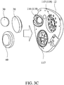
- Fig. 3C shows the low-pitch speaker 20, the high-pitch speaker 30, and the crossfeed speaker 40.
- the second layer structure 12 comprises a first receiving space 115, a third receiving space 116 and a second receiving space 117.
- the first receiving space 115 includes a first inclined surface 118.
- the third receiving space 116 comprises a second inclined surface 119.
- the low-pitch speaker 20 is embedded into the first receiving space 115 and is in contact with the first inclined surface 118.
- the high-pitch speaker 30 is embedded into the third receiving space 116 and is in contact with the second inclined surface 119.
- the crossfeed speaker 40 is embedded into the second receiving space 117.
- Figs. 4A and 4B show a detailed structure of the first layer structure 11, wherein the low-pitch auxiliary path 21 extends into the first layer structure 11, and passes through the first layer structure 11 to the sound output side 19.
- the first layer structure 11 includes a first trench 122 and a third through hole 123. At least a portion of the first trench 122 extends around the low-pitch speaker 20 and is connected to the third through hole 123.
- the low-pitch auxiliary path 21 extends along the first trench 122 and the third through hole 123, and leaves the first layer structure 11.
- the first trench 122 includes a comb-shaped portion 122A, and the comb-shaped portion 122A delays the transmission of the sound.
- the first layer structure 11 includes a third trench 124 and a fourth through hole 125. At least a portion of the third trench 124 extends around the high-pitch speaker 30 and is connected to the fourth through hole 125.
- the high-pitch auxiliary path 31 extends along the third trench 124 and the fourth through hole 125, and leaves the first layer structure 11. In one embodiment, at least a portion of the third trench 124 surrounds the low-pitch speaker 20.
- the third through hole 123 is adjacent to the fourth through hole 125.
- the second through hole 121 is placed between the low-pitch speaker 20 and the high-pitch speaker 30.
- the low-pitch speaker 20 is placed between the second through hole 121 and the third through hole 123.
- the comb-shaped portion 122A, the second through hole 121, the third through hole 123 and the fourth through hole 125 are arranged around the low-pitch speaker 20.
- both the left ear and the right ear of the user can hear the sound of the right sound channel and the left sound channel.
- the design of the protrusion and the design of the path length and the shapes of the second trench and the third trench modify the time difference of the sound therein. Additionally, the frequency can be modified by the design of breathable holes and the first trench.
- the volume of the low-pitch speaker 20 and the high-pitch speaker 30 when the volume of the low-pitch speaker 20 and the high-pitch speaker 30 is high, the volume of the crossfeed speaker 40 is low. When the volume of the low-pitch speaker 20 and the high-pitch speaker 30 is low, the volume of the crossfeed speaker 40 is high. Stereo sound is thereby provided.
- the headphone further includes a vent 15.
- the vent 15 is formed on a side of the housing 10, and communicates with outside air.
- Figs. 5A and 5B shows a headphone of another embodiment of the invention, wherein the crossfeed output path 41 extends between the second layer structure 12 and the cover structure 13, and passes through the second layer structure 12 and the first layer structure 11 to the sound output side 19.
- the second layer structure 12 includes an opening portion 111, a second trench 112' and a first through hole 113.
- the opening portion 111 corresponds to the crossfeed speaker 40.
- the second trench 112' is communicated to the opening portion 111 and the first through hole 113.
- the crossfeed output path 41 extends along the opening portion 111, the second trench 112' and the first through hole 113 to leave the second layer structure 12.
- the cover structure 13 includes a sound chamber 131'.
- the sound chamber 131' is connected to the opening portion 111 and the second trench 112'.
- the crossfeed output path 41 passes from the opening portion 111, the sound chamber 131', the second trench 112' and the first through hole 113 to leave the second layer structure 12.
- the sound chamber 131' is utilized to modify the frequency characteristics.
Landscapes
- Engineering & Computer Science (AREA)
- Physics & Mathematics (AREA)
- Acoustics & Sound (AREA)
- Signal Processing (AREA)
- Manufacturing & Machinery (AREA)
- Health & Medical Sciences (AREA)
- Otolaryngology (AREA)
- Headphones And Earphones (AREA)
Claims (15)
- Ein Kopfhörer (1), umfassend:ein Gehäuse (10), umfassend eine erste Schichtstruktur (11), einen ersten Aufnahmeraum (115), einen ersten Ausgabepfad (21), einen ersten Kanal (122), eine zweite Schichtstruktur (12), eine Abdeckstruktur (13) und eine Schallausgangsseite (19); undeinen Lautsprecher (20), der in dem ersten Aufnahmeraum (115) angeordnet ist, wobei der Lautsprecher eine erste Lautsprecherausrichtung umfasst und die erste Lautsprecherausrichtung dem ersten Ausgabepfad entspricht,wobei der erste Ausgabepfad (21) den ersten Kanal (122) umfasst,wobei der erste Kanal (122) an der ersten Schichtstruktur (11) angeordnet ist, sich um den Lautsprecher erstreckt und mit der Schallausgangsseite verbunden ist,wobei das Gehäuse ferner einen zweiten Ausgabepfad (22) umfasst, der Lautsprecher ferner eine zweite Lautsprecherausrichtung umfasst und die zweite Lautsprecherausrichtung dem zweiten Ausgabepfad entspricht, wobei ein Crossfeed-Ausgabepfad (41) zwischen der zweiten Schichtstruktur und der Abdeckungsstruktur verläuft, der durch die zweite Schichtstruktur und die erste Schichtstruktur zur Schallausgangsseite verläuft, wobei der Lautsprecher in Kontakt mit einer ersten geneigten Oberfläche (118) steht, die in dem ersten Aufnahmeraum enthalten ist.
- Der Kopfhörer nach Anspruch 1, wobei die erste Lautsprecherausrichtung neben der zweiten Lautsprecherausrichtung angeordnet ist und die erste Lautsprecherausrichtung und die zweite Lautsprecherausrichtung in einem geneigten Winkel von etwa -10°∼10° angeordnet sind.
- Der Kopfhörer nach Anspruch 1 oder 2, wobei die erste Lautsprecherausrichtung und die zweite Lautsprecherausrichtung Klänge mit der gleichen Frequenz oder unterschiedlichen Frequenzen bereitstellen, die erste Lautsprecherausrichtung eine erste Lautsprecherfläche umfasst und die zweite Lautsprecherausrichtung eine zweite Lautsprecherfläche umfasst.
- Der Kopfhörer nach einem der Ansprüche 1 bis 3, wobei eine Länge des ersten Ausgabepfades länger ist als eine Länge des zweiten Ausgabepfades.
- Der Kopfhörer nach einem der Ansprüche 1 bis 4, wobei die zweite Schichtstruktur des Gehäuses einen Öffnungsabschnitt (111), einen Vorsprung (112) und ein erstes Durchgangsloch (113) umfasst, und der Öffnungsabschnitt einem Crossfeed-Lautsprecher (40) entspricht, und die Abdeckstruktur des Gehäuses einen zweiten Schlitz umfasst, wobei der zweite Schlitz dem Öffnungsabschnitt, dem Vorsprung und dem ersten Durchgangsloch (113) entspricht und der Crossfeed-Ausgangspfad entlang des Öffnungsabschnitts, des zweiten Kanals und des ersten Durchgangslochs (113) verläuft.
- Der Kopfhörer nach einem der Ansprüche 1 bis 5, ferner umfassend einen Crossfeed-Lautsprecher, wobei der Crossfeed-Lautsprecher eine Crossfeed-Lautsprecherausrichtung umfasst, die Crossfeed-Lautsprecherausrichtung dem Crossfeed-Ausgabepfad entspricht, wobei das Gehäuse ferner einen zweiten Aufnahmeraum umfasst und der Crossfeed-Lautsprecher in den zweiten Aufnahmeraum platziert ist.
- Der Kopfhörer nach Anspruch 6, wobei die zweite Schichtstruktur zwischen der ersten Schichtstruktur und der Abdeckstruktur angeordnet ist, die erste Schichtstruktur zwischen der zweiten Schichtstruktur und der Schallausgangsseite angeordnet ist, der erste Aufnahmeraum und der zweite Aufnahmeraum in der zweiten Schichtstruktur angeordnet sind und der Lautsprecher und der Crossfeed-Lautsprecher in der ersten Schichtstruktur angeordnet sind.
- Der Kopfhörer nach Anspruch 7, wobei die zweite Schichtstruktur einen Öffnungsabschnitt, einen Vorsprung und ein erstes Durchgangsloch umfasst und der Öffnungsabschnitt dem Crossfeed-Lautsprecher entspricht, die Abdeckstruktur einen zweiten Kanal umfasst, der zweite Kanal dem Öffnungsabschnitt, dem Vorsprung und dem ersten Durchgangsloch entspricht und der Crossfeed-Ausgangspfad entlang des Öffnungsabschnitts, des zweiten Kanals und des ersten Durchgangslochs verläuft, um die zweite Schichtstruktur zu verlassen.
- Der Kopfhörer nach Anspruch 8, wobei die erste Schichtstruktur ein zweites Durchgangsloch umfasst, das zweite Durchgangsloch dem ersten Durchgangsloch entspricht und der Crossfeed-Ausgangspfad von der zweiten Schichtstruktur entlang des ersten Durchgangslochs und des zweiten Durchgangslochs durch die erste Schichtstruktur zur Schallausgangsseite verläuft.
- Der Kopfhörer nach Anspruch 9, wobei sich der zweite Ausgabepfad in die erste Schichtstruktur erstreckt und durch die erste Schichtstruktur zur Schallausgangsseite führt.
- Der Kopfhörer nach Anspruch 9 oder 10, wobei die erste Schichtstruktur ein drittes Durchgangsloch umfasst, das dritte Durchgangsloch mit dem ersten Kanal verbunden ist und der erste Ausgangspfad entlang des ersten Kanals und des dritten Durchgangslochs verläuft, um die erste Schichtstruktur zu verlassen.
- Der Kopfhörer nach Anspruch 11, wobei der erste Kanal einen kammartigen Abschnitt umfasst.
- Der Kopfhörer nach Anspruch 12, wobei der kammartige Abschnitt, das zweite Durchgangsloch und das dritte Durchgangsloch um den Lautsprecher herum angeordnet sind.
- Der Kopfhörer nach einem der Ansprüche 11 bis 13, wobei der Lautsprecher zwischen dem zweiten Durchgangsloch und dem dritten Durchgangsloch angeordnet ist.
- Der Kopfhörer nach einem der Ansprüche 7 bis 14, wobei die Struktur der zweiten Schicht ferner eine Vielzahl von Öffnungen umfasst und die Öffnungen dem Lautsprecher entsprechen.
Applications Claiming Priority (1)
| Application Number | Priority Date | Filing Date | Title |
|---|---|---|---|
| CN201610054554.9A CN107018458B (zh) | 2016-01-27 | 2016-01-27 | 耳机 |
Publications (2)
| Publication Number | Publication Date |
|---|---|
| EP3200476A1 EP3200476A1 (de) | 2017-08-02 |
| EP3200476B1 true EP3200476B1 (de) | 2020-01-15 |
Family
ID=57178328
Family Applications (1)
| Application Number | Title | Priority Date | Filing Date |
|---|---|---|---|
| EP16194773.4A Active EP3200476B1 (de) | 2016-01-27 | 2016-10-20 | Kopfhörer |
Country Status (4)
| Country | Link |
|---|---|
| US (1) | US10165344B2 (de) |
| EP (1) | EP3200476B1 (de) |
| JP (1) | JP6312785B2 (de) |
| CN (1) | CN107018458B (de) |
Families Citing this family (4)
| Publication number | Priority date | Publication date | Assignee | Title |
|---|---|---|---|---|
| US10757502B2 (en) * | 2018-06-21 | 2020-08-25 | Merry Electronics(Shenzhen) Co., Ltd. | Speaker |
| CN110267180B (zh) * | 2019-07-26 | 2020-10-20 | 维沃移动通信(杭州)有限公司 | 电子设备 |
| JP7462230B2 (ja) * | 2021-04-30 | 2024-04-05 | パナソニックIpマネジメント株式会社 | ヘッドセットおよびイヤーパッド |
| CN117837169A (zh) * | 2021-09-18 | 2024-04-05 | 三星电子株式会社 | 包括扬声器的可穿戴装置 |
Citations (1)
| Publication number | Priority date | Publication date | Assignee | Title |
|---|---|---|---|---|
| US4005278A (en) * | 1974-09-16 | 1977-01-25 | Akg Akustische U. Kino-Gerate Gesellschaft M.B.H. | Headphone |
Family Cites Families (15)
| Publication number | Priority date | Publication date | Assignee | Title |
|---|---|---|---|---|
| JP3521825B2 (ja) * | 1999-12-28 | 2004-04-26 | 株式会社村田製作所 | スピーカシステム |
| KR20010103813A (ko) * | 2001-08-24 | 2001-11-24 | 김성일 | 저음 반사형 헤드폰 |
| CN1264381C (zh) | 2001-11-27 | 2006-07-12 | 黄瑞书 | 改进的耳机 |
| US20030103637A1 (en) * | 2001-12-04 | 2003-06-05 | Jui-Shu Huang | Headphone |
| US7340071B2 (en) * | 2001-12-04 | 2008-03-04 | Jui-Shu Huang | Headphones with a multichannel guiding mechanism |
| JP2003199187A (ja) * | 2001-12-17 | 2003-07-11 | Zuisho Ko | ヘッドフォン |
| US20050238189A1 (en) * | 2004-04-23 | 2005-10-27 | Gamma Inc. | Headphone device with surround sound effect |
| EP1608204A1 (de) * | 2004-06-09 | 2005-12-21 | Jui-Shu Huang | Kopfhörer mit mehrkanaliger Leiteinrichtung |
| US7916888B2 (en) * | 2006-06-30 | 2011-03-29 | Bose Corporation | In-ear headphones |
| TWM318871U (en) * | 2007-04-04 | 2007-09-11 | Cotron Corp | Multiple channel earphone and structure thereof |
| WO2010134653A1 (ko) * | 2009-05-22 | 2010-11-25 | 에스에프원(주) | 다채널 헤드폰 시스템 |
| TWI471020B (zh) * | 2011-09-26 | 2015-01-21 | 潘建全 | 具可活動切換結構之多聲道掛載式揚聲裝置及其組裝方法 |
| CN103067827B (zh) | 2011-10-21 | 2015-05-20 | 潘建全 | 具可活动切换结构的多声道挂载式扬声装置及其组装方法 |
| KR101310879B1 (ko) * | 2012-06-19 | 2013-09-25 | 김흥배 | 이어폰 |
| CN204069266U (zh) | 2014-09-01 | 2014-12-31 | 常州阿木奇声学科技有限公司 | 一种双喇叭式入耳式耳塞 |
-
2016
- 2016-01-27 CN CN201610054554.9A patent/CN107018458B/zh active Active
- 2016-10-13 US US15/292,829 patent/US10165344B2/en active Active
- 2016-10-20 EP EP16194773.4A patent/EP3200476B1/de active Active
- 2016-12-22 JP JP2016249217A patent/JP6312785B2/ja active Active
Patent Citations (1)
| Publication number | Priority date | Publication date | Assignee | Title |
|---|---|---|---|---|
| US4005278A (en) * | 1974-09-16 | 1977-01-25 | Akg Akustische U. Kino-Gerate Gesellschaft M.B.H. | Headphone |
Also Published As
| Publication number | Publication date |
|---|---|
| EP3200476A1 (de) | 2017-08-02 |
| US20170214993A1 (en) | 2017-07-27 |
| US10165344B2 (en) | 2018-12-25 |
| CN107018458B (zh) | 2020-02-21 |
| CN107018458A (zh) | 2017-08-04 |
| JP2017135700A (ja) | 2017-08-03 |
| JP6312785B2 (ja) | 2018-04-18 |
Similar Documents
| Publication | Publication Date | Title |
|---|---|---|
| EP3276980B1 (de) | Ohrhörer | |
| JP5363825B2 (ja) | ノイズキャンセルヘッドホン | |
| US8139806B2 (en) | Earphone for placement in an ear | |
| USRE48424E1 (en) | Custom fit in-ear monitors utilizing a single piece driver module | |
| JP6380504B2 (ja) | ヘッドホン | |
| CN102196330B (zh) | 耳机 | |
| JP2009219122A (ja) | インイヤーイヤホン | |
| KR101423570B1 (ko) | 이어폰 | |
| JP7264052B2 (ja) | 音響出力装置 | |
| US10721549B2 (en) | Direct-radiating earphone drivers | |
| KR101310879B1 (ko) | 이어폰 | |
| US10165344B2 (en) | Headphone | |
| JP2019145964A (ja) | イヤホン | |
| JP5872722B1 (ja) | 連通管付きイヤホン | |
| JP4879675B2 (ja) | 音誘導チューブを有するイヤホン | |
| EP3200477B1 (de) | Kopfhörer | |
| JP5849296B1 (ja) | 連通部付き密閉イヤホン | |
| JP6863687B2 (ja) | イヤホン | |
| JPH04347997A (ja) | ヘッドホン | |
| US20080199035A1 (en) | In-Ear Phone | |
| JP2021100230A (ja) | 聴取装置 | |
| TWI602439B (zh) | 耳機 | |
| JP2016201786A (ja) | 連通管付きイヤホン | |
| TW201731300A (zh) | 具雙獨立揚聲器之耳機 | |
| KR20060000239A (ko) | 다중 채널 안내 기구를 구비한 헤드폰 |
Legal Events
| Date | Code | Title | Description |
|---|---|---|---|
| PUAI | Public reference made under article 153(3) epc to a published international application that has entered the european phase |
Free format text: ORIGINAL CODE: 0009012 |
|
| STAA | Information on the status of an ep patent application or granted ep patent |
Free format text: STATUS: THE APPLICATION HAS BEEN PUBLISHED |
|
| AK | Designated contracting states |
Kind code of ref document: A1 Designated state(s): AL AT BE BG CH CY CZ DE DK EE ES FI FR GB GR HR HU IE IS IT LI LT LU LV MC MK MT NL NO PL PT RO RS SE SI SK SM TR |
|
| AX | Request for extension of the european patent |
Extension state: BA ME |
|
| STAA | Information on the status of an ep patent application or granted ep patent |
Free format text: STATUS: REQUEST FOR EXAMINATION WAS MADE |
|
| 17P | Request for examination filed |
Effective date: 20180201 |
|
| RBV | Designated contracting states (corrected) |
Designated state(s): AL AT BE BG CH CY CZ DE DK EE ES FI FR GB GR HR HU IE IS IT LI LT LU LV MC MK MT NL NO PL PT RO RS SE SI SK SM TR |
|
| STAA | Information on the status of an ep patent application or granted ep patent |
Free format text: STATUS: EXAMINATION IS IN PROGRESS |
|
| 17Q | First examination report despatched |
Effective date: 20181030 |
|
| GRAP | Despatch of communication of intention to grant a patent |
Free format text: ORIGINAL CODE: EPIDOSNIGR1 |
|
| STAA | Information on the status of an ep patent application or granted ep patent |
Free format text: STATUS: GRANT OF PATENT IS INTENDED |
|
| RIC1 | Information provided on ipc code assigned before grant |
Ipc: H04R 1/28 20060101ALN20190710BHEP Ipc: H04R 1/10 20060101AFI20190710BHEP Ipc: H04R 1/26 20060101ALN20190710BHEP Ipc: H04R 5/033 20060101ALN20190710BHEP Ipc: H04R 1/32 20060101ALI20190710BHEP Ipc: H04R 1/24 20060101ALN20190710BHEP |
|
| INTG | Intention to grant announced |
Effective date: 20190807 |
|
| GRAS | Grant fee paid |
Free format text: ORIGINAL CODE: EPIDOSNIGR3 |
|
| GRAA | (expected) grant |
Free format text: ORIGINAL CODE: 0009210 |
|
| STAA | Information on the status of an ep patent application or granted ep patent |
Free format text: STATUS: THE PATENT HAS BEEN GRANTED |
|
| AK | Designated contracting states |
Kind code of ref document: B1 Designated state(s): AL AT BE BG CH CY CZ DE DK EE ES FI FR GB GR HR HU IE IS IT LI LT LU LV MC MK MT NL NO PL PT RO RS SE SI SK SM TR |
|
| REG | Reference to a national code |
Ref country code: CH Ref legal event code: EP Ref country code: GB Ref legal event code: FG4D |
|
| REG | Reference to a national code |
Ref country code: IE Ref legal event code: FG4D |
|
| REG | Reference to a national code |
Ref country code: DE Ref legal event code: R096 Ref document number: 602016028207 Country of ref document: DE |
|
| REG | Reference to a national code |
Ref country code: AT Ref legal event code: REF Ref document number: 1226214 Country of ref document: AT Kind code of ref document: T Effective date: 20200215 |
|
| REG | Reference to a national code |
Ref country code: NL Ref legal event code: MP Effective date: 20200115 |
|
| REG | Reference to a national code |
Ref country code: LT Ref legal event code: MG4D |
|
| PG25 | Lapsed in a contracting state [announced via postgrant information from national office to epo] |
Ref country code: RS Free format text: LAPSE BECAUSE OF FAILURE TO SUBMIT A TRANSLATION OF THE DESCRIPTION OR TO PAY THE FEE WITHIN THE PRESCRIBED TIME-LIMIT Effective date: 20200115 Ref country code: FI Free format text: LAPSE BECAUSE OF FAILURE TO SUBMIT A TRANSLATION OF THE DESCRIPTION OR TO PAY THE FEE WITHIN THE PRESCRIBED TIME-LIMIT Effective date: 20200115 Ref country code: PT Free format text: LAPSE BECAUSE OF FAILURE TO SUBMIT A TRANSLATION OF THE DESCRIPTION OR TO PAY THE FEE WITHIN THE PRESCRIBED TIME-LIMIT Effective date: 20200607 Ref country code: NO Free format text: LAPSE BECAUSE OF FAILURE TO SUBMIT A TRANSLATION OF THE DESCRIPTION OR TO PAY THE FEE WITHIN THE PRESCRIBED TIME-LIMIT Effective date: 20200415 Ref country code: NL Free format text: LAPSE BECAUSE OF FAILURE TO SUBMIT A TRANSLATION OF THE DESCRIPTION OR TO PAY THE FEE WITHIN THE PRESCRIBED TIME-LIMIT Effective date: 20200115 |
|
| PG25 | Lapsed in a contracting state [announced via postgrant information from national office to epo] |
Ref country code: LV Free format text: LAPSE BECAUSE OF FAILURE TO SUBMIT A TRANSLATION OF THE DESCRIPTION OR TO PAY THE FEE WITHIN THE PRESCRIBED TIME-LIMIT Effective date: 20200115 Ref country code: SE Free format text: LAPSE BECAUSE OF FAILURE TO SUBMIT A TRANSLATION OF THE DESCRIPTION OR TO PAY THE FEE WITHIN THE PRESCRIBED TIME-LIMIT Effective date: 20200115 Ref country code: IS Free format text: LAPSE BECAUSE OF FAILURE TO SUBMIT A TRANSLATION OF THE DESCRIPTION OR TO PAY THE FEE WITHIN THE PRESCRIBED TIME-LIMIT Effective date: 20200515 Ref country code: BG Free format text: LAPSE BECAUSE OF FAILURE TO SUBMIT A TRANSLATION OF THE DESCRIPTION OR TO PAY THE FEE WITHIN THE PRESCRIBED TIME-LIMIT Effective date: 20200415 Ref country code: GR Free format text: LAPSE BECAUSE OF FAILURE TO SUBMIT A TRANSLATION OF THE DESCRIPTION OR TO PAY THE FEE WITHIN THE PRESCRIBED TIME-LIMIT Effective date: 20200416 Ref country code: HR Free format text: LAPSE BECAUSE OF FAILURE TO SUBMIT A TRANSLATION OF THE DESCRIPTION OR TO PAY THE FEE WITHIN THE PRESCRIBED TIME-LIMIT Effective date: 20200115 |
|
| REG | Reference to a national code |
Ref country code: DE Ref legal event code: R097 Ref document number: 602016028207 Country of ref document: DE |
|
| PG25 | Lapsed in a contracting state [announced via postgrant information from national office to epo] |
Ref country code: SM Free format text: LAPSE BECAUSE OF FAILURE TO SUBMIT A TRANSLATION OF THE DESCRIPTION OR TO PAY THE FEE WITHIN THE PRESCRIBED TIME-LIMIT Effective date: 20200115 Ref country code: LT Free format text: LAPSE BECAUSE OF FAILURE TO SUBMIT A TRANSLATION OF THE DESCRIPTION OR TO PAY THE FEE WITHIN THE PRESCRIBED TIME-LIMIT Effective date: 20200115 Ref country code: EE Free format text: LAPSE BECAUSE OF FAILURE TO SUBMIT A TRANSLATION OF THE DESCRIPTION OR TO PAY THE FEE WITHIN THE PRESCRIBED TIME-LIMIT Effective date: 20200115 Ref country code: DK Free format text: LAPSE BECAUSE OF FAILURE TO SUBMIT A TRANSLATION OF THE DESCRIPTION OR TO PAY THE FEE WITHIN THE PRESCRIBED TIME-LIMIT Effective date: 20200115 Ref country code: SK Free format text: LAPSE BECAUSE OF FAILURE TO SUBMIT A TRANSLATION OF THE DESCRIPTION OR TO PAY THE FEE WITHIN THE PRESCRIBED TIME-LIMIT Effective date: 20200115 Ref country code: ES Free format text: LAPSE BECAUSE OF FAILURE TO SUBMIT A TRANSLATION OF THE DESCRIPTION OR TO PAY THE FEE WITHIN THE PRESCRIBED TIME-LIMIT Effective date: 20200115 Ref country code: RO Free format text: LAPSE BECAUSE OF FAILURE TO SUBMIT A TRANSLATION OF THE DESCRIPTION OR TO PAY THE FEE WITHIN THE PRESCRIBED TIME-LIMIT Effective date: 20200115 Ref country code: CZ Free format text: LAPSE BECAUSE OF FAILURE TO SUBMIT A TRANSLATION OF THE DESCRIPTION OR TO PAY THE FEE WITHIN THE PRESCRIBED TIME-LIMIT Effective date: 20200115 |
|
| REG | Reference to a national code |
Ref country code: AT Ref legal event code: MK05 Ref document number: 1226214 Country of ref document: AT Kind code of ref document: T Effective date: 20200115 |
|
| PLBE | No opposition filed within time limit |
Free format text: ORIGINAL CODE: 0009261 |
|
| STAA | Information on the status of an ep patent application or granted ep patent |
Free format text: STATUS: NO OPPOSITION FILED WITHIN TIME LIMIT |
|
| 26N | No opposition filed |
Effective date: 20201016 |
|
| PG25 | Lapsed in a contracting state [announced via postgrant information from national office to epo] |
Ref country code: IT Free format text: LAPSE BECAUSE OF FAILURE TO SUBMIT A TRANSLATION OF THE DESCRIPTION OR TO PAY THE FEE WITHIN THE PRESCRIBED TIME-LIMIT Effective date: 20200115 Ref country code: AT Free format text: LAPSE BECAUSE OF FAILURE TO SUBMIT A TRANSLATION OF THE DESCRIPTION OR TO PAY THE FEE WITHIN THE PRESCRIBED TIME-LIMIT Effective date: 20200115 |
|
| PG25 | Lapsed in a contracting state [announced via postgrant information from national office to epo] |
Ref country code: SI Free format text: LAPSE BECAUSE OF FAILURE TO SUBMIT A TRANSLATION OF THE DESCRIPTION OR TO PAY THE FEE WITHIN THE PRESCRIBED TIME-LIMIT Effective date: 20200115 Ref country code: PL Free format text: LAPSE BECAUSE OF FAILURE TO SUBMIT A TRANSLATION OF THE DESCRIPTION OR TO PAY THE FEE WITHIN THE PRESCRIBED TIME-LIMIT Effective date: 20200115 |
|
| REG | Reference to a national code |
Ref country code: CH Ref legal event code: PL |
|
| PG25 | Lapsed in a contracting state [announced via postgrant information from national office to epo] |
Ref country code: MC Free format text: LAPSE BECAUSE OF FAILURE TO SUBMIT A TRANSLATION OF THE DESCRIPTION OR TO PAY THE FEE WITHIN THE PRESCRIBED TIME-LIMIT Effective date: 20200115 Ref country code: LU Free format text: LAPSE BECAUSE OF NON-PAYMENT OF DUE FEES Effective date: 20201020 |
|
| REG | Reference to a national code |
Ref country code: BE Ref legal event code: MM Effective date: 20201031 |
|
| PG25 | Lapsed in a contracting state [announced via postgrant information from national office to epo] |
Ref country code: FR Free format text: LAPSE BECAUSE OF NON-PAYMENT OF DUE FEES Effective date: 20201031 |
|
| PG25 | Lapsed in a contracting state [announced via postgrant information from national office to epo] |
Ref country code: CH Free format text: LAPSE BECAUSE OF NON-PAYMENT OF DUE FEES Effective date: 20201031 Ref country code: BE Free format text: LAPSE BECAUSE OF NON-PAYMENT OF DUE FEES Effective date: 20201031 Ref country code: LI Free format text: LAPSE BECAUSE OF NON-PAYMENT OF DUE FEES Effective date: 20201031 |
|
| PG25 | Lapsed in a contracting state [announced via postgrant information from national office to epo] |
Ref country code: IE Free format text: LAPSE BECAUSE OF NON-PAYMENT OF DUE FEES Effective date: 20201020 |
|
| PG25 | Lapsed in a contracting state [announced via postgrant information from national office to epo] |
Ref country code: TR Free format text: LAPSE BECAUSE OF FAILURE TO SUBMIT A TRANSLATION OF THE DESCRIPTION OR TO PAY THE FEE WITHIN THE PRESCRIBED TIME-LIMIT Effective date: 20200115 Ref country code: MT Free format text: LAPSE BECAUSE OF FAILURE TO SUBMIT A TRANSLATION OF THE DESCRIPTION OR TO PAY THE FEE WITHIN THE PRESCRIBED TIME-LIMIT Effective date: 20200115 Ref country code: CY Free format text: LAPSE BECAUSE OF FAILURE TO SUBMIT A TRANSLATION OF THE DESCRIPTION OR TO PAY THE FEE WITHIN THE PRESCRIBED TIME-LIMIT Effective date: 20200115 |
|
| PG25 | Lapsed in a contracting state [announced via postgrant information from national office to epo] |
Ref country code: MK Free format text: LAPSE BECAUSE OF FAILURE TO SUBMIT A TRANSLATION OF THE DESCRIPTION OR TO PAY THE FEE WITHIN THE PRESCRIBED TIME-LIMIT Effective date: 20200115 Ref country code: AL Free format text: LAPSE BECAUSE OF FAILURE TO SUBMIT A TRANSLATION OF THE DESCRIPTION OR TO PAY THE FEE WITHIN THE PRESCRIBED TIME-LIMIT Effective date: 20200115 |
|
| PGFP | Annual fee paid to national office [announced via postgrant information from national office to epo] |
Ref country code: GB Payment date: 20240814 Year of fee payment: 9 |
|
| PGFP | Annual fee paid to national office [announced via postgrant information from national office to epo] |
Ref country code: DE Payment date: 20241031 Year of fee payment: 9 |