EP3200480B1 - Hearing aid device with integrated antenna - Google Patents
Hearing aid device with integrated antenna Download PDFInfo
- Publication number
- EP3200480B1 EP3200480B1 EP17161852.3A EP17161852A EP3200480B1 EP 3200480 B1 EP3200480 B1 EP 3200480B1 EP 17161852 A EP17161852 A EP 17161852A EP 3200480 B1 EP3200480 B1 EP 3200480B1
- Authority
- EP
- European Patent Office
- Prior art keywords
- hearing aid
- antenna
- aid device
- hook
- housing
- Prior art date
- Legal status (The legal status is an assumption and is not a legal conclusion. Google has not performed a legal analysis and makes no representation as to the accuracy of the status listed.)
- Active
Links
Images
Classifications
-
- H—ELECTRICITY
- H04—ELECTRIC COMMUNICATION TECHNIQUE
- H04R—LOUDSPEAKERS, MICROPHONES, GRAMOPHONE PICK-UPS OR LIKE ACOUSTIC ELECTROMECHANICAL TRANSDUCERS; ELECTRIC HEARING AIDS; PUBLIC ADDRESS SYSTEMS
- H04R25/00—Electric hearing aids
- H04R25/55—Electric hearing aids using an external connection, either wireless or wired
- H04R25/554—Electric hearing aids using an external connection, either wireless or wired using a wireless connection, e.g. between microphone and amplifier or using Tcoils
-
- H—ELECTRICITY
- H01—ELECTRIC ELEMENTS
- H01Q—ANTENNAS, i.e. RADIO AERIALS
- H01Q1/00—Details of, or arrangements associated with, antennas
- H01Q1/12—Supports; Mounting means
- H01Q1/22—Supports; Mounting means by structural association with other equipment or articles
- H01Q1/2291—Supports; Mounting means by structural association with other equipment or articles used in Bluetooth® or Wi-Fi® devices of Wireless Local Area Networks [WLAN]
-
- H—ELECTRICITY
- H01—ELECTRIC ELEMENTS
- H01Q—ANTENNAS, i.e. RADIO AERIALS
- H01Q1/00—Details of, or arrangements associated with, antennas
- H01Q1/27—Adaptation for use in or on movable bodies
- H01Q1/273—Adaptation for carrying or wearing by persons or animals
-
- H—ELECTRICITY
- H01—ELECTRIC ELEMENTS
- H01Q—ANTENNAS, i.e. RADIO AERIALS
- H01Q1/00—Details of, or arrangements associated with, antennas
- H01Q1/40—Radiating elements coated with or embedded in protective material
-
- H—ELECTRICITY
- H04—ELECTRIC COMMUNICATION TECHNIQUE
- H04R—LOUDSPEAKERS, MICROPHONES, GRAMOPHONE PICK-UPS OR LIKE ACOUSTIC ELECTROMECHANICAL TRANSDUCERS; ELECTRIC HEARING AIDS; PUBLIC ADDRESS SYSTEMS
- H04R25/00—Electric hearing aids
- H04R25/40—Arrangements for obtaining a desired directivity characteristic
- H04R25/402—Arrangements for obtaining a desired directivity characteristic using contructional means
-
- H—ELECTRICITY
- H04—ELECTRIC COMMUNICATION TECHNIQUE
- H04R—LOUDSPEAKERS, MICROPHONES, GRAMOPHONE PICK-UPS OR LIKE ACOUSTIC ELECTROMECHANICAL TRANSDUCERS; ELECTRIC HEARING AIDS; PUBLIC ADDRESS SYSTEMS
- H04R2225/00—Details of deaf aids covered by H04R25/00, not provided for in any of its subgroups
- H04R2225/021—Behind the ear [BTE] hearing aids
-
- H—ELECTRICITY
- H04—ELECTRIC COMMUNICATION TECHNIQUE
- H04R—LOUDSPEAKERS, MICROPHONES, GRAMOPHONE PICK-UPS OR LIKE ACOUSTIC ELECTROMECHANICAL TRANSDUCERS; ELECTRIC HEARING AIDS; PUBLIC ADDRESS SYSTEMS
- H04R2225/00—Details of deaf aids covered by H04R25/00, not provided for in any of its subgroups
- H04R2225/021—Behind the ear [BTE] hearing aids
- H04R2225/0213—Constructional details of earhooks, e.g. shape, material
-
- H—ELECTRICITY
- H04—ELECTRIC COMMUNICATION TECHNIQUE
- H04R—LOUDSPEAKERS, MICROPHONES, GRAMOPHONE PICK-UPS OR LIKE ACOUSTIC ELECTROMECHANICAL TRANSDUCERS; ELECTRIC HEARING AIDS; PUBLIC ADDRESS SYSTEMS
- H04R2225/00—Details of deaf aids covered by H04R25/00, not provided for in any of its subgroups
- H04R2225/51—Aspects of antennas or their circuitry in or for hearing aids
-
- H—ELECTRICITY
- H04—ELECTRIC COMMUNICATION TECHNIQUE
- H04R—LOUDSPEAKERS, MICROPHONES, GRAMOPHONE PICK-UPS OR LIKE ACOUSTIC ELECTROMECHANICAL TRANSDUCERS; ELECTRIC HEARING AIDS; PUBLIC ADDRESS SYSTEMS
- H04R25/00—Electric hearing aids
-
- H—ELECTRICITY
- H04—ELECTRIC COMMUNICATION TECHNIQUE
- H04R—LOUDSPEAKERS, MICROPHONES, GRAMOPHONE PICK-UPS OR LIKE ACOUSTIC ELECTROMECHANICAL TRANSDUCERS; ELECTRIC HEARING AIDS; PUBLIC ADDRESS SYSTEMS
- H04R25/00—Electric hearing aids
- H04R25/60—Mounting or interconnection of hearing aid parts, e.g. inside tips, housings or to ossicles
- H04R25/607—Mounting or interconnection of hearing aid parts, e.g. inside tips, housings or to ossicles of earhooks
Definitions
- the present invention generally relates to a hearing aid device.
- the invention more particularly relates to a hearing aid device that is configured to communicate wirelessly with an external device.
- Recent hearing aid devices are adapted for communicating wirelessly with external devices. It is known to configure a hearing aid device to transmit a wireless signal to a corresponding hearing aid device (arranged in the other ear) in order to simultaneously change e.g. background settings of two hearings aid devices arranged in the both ears of a user.
- US 2010/321269 A1 discloses a hearing aid comprising a casing and a sound tube providing both an ear hooking function.
- the receiver is located in the casing of the hearing aid.
- US 2013/223664 A1 discloses a hearing aid comprising an ear hook and an antenna located in the ear hook. The receiver is also located in said ear hook.
- hearing aid device When hearing aid device has to be configured to perform wireless communication there are a number of specific requirements to be considered, such as the size and position of the antenna.
- the hearing aid device is a hearing aid device configured to communicate wirelessly with an external device, where the hearing aid device comprises a housing with a microphone and an amplifier, where the hearing aid device further comprises an antenna and a hook provided with a through-going bore configured to deliver air-borne sound acoustically from a receiver in the housing to an ear mould for dome via a tube connected to the hook, the tube configured to be attached to the distal end of the hook and the antenna extends along a portion of the hook and that the antenna is embedded into the wall of the hook.
- Such hearing aid device makes it possible to provide effective wireless communication with an external device. Moreover it is possible to arrange the antenna within a hearing aid device in a manner that facilitates effective wireless communication with an external device.
- the hearing aid device is a hearing aid device configured to communicate wirelessly with an external device.
- the external device may in principle be any suitable device e.g. a mobile phone, a computer, another hearing aid, a remote control, a wireless relay device adapted to advance an audio signal from another communication application, or the like.
- the hearing aid device may be configured to communicate wirelessly by using any wireless technology, however, it may be an advantage to use a wireless technology standard for exchanging data over short distances by using short-wavelength radio transmissions, e.g. Bluetooth applying the ISM band from 2400-2480 MHz.
- a wireless technology standard for exchanging data over short distances by using short-wavelength radio transmissions, e.g. Bluetooth applying the ISM band from 2400-2480 MHz.
- the hearing aid device comprises a housing (which also may be referred to as a casing) with a microphone and an amplifier.
- the hearing aid device may comprise several microphones and the microphone(s) may be of any suitable type.
- the amplifier may be of any suitable type.
- the housing is configured to receive a battery for delivery of energy to the hearing aid device.
- the antenna may be any suitable type of antenna made in any suitable material and having any suitable form.
- the hearing aid device may be a behind-the-ear (BTE) hearing aid device by way of example.
- BTE behind-the-ear
- a hearing aid device refers to a device, such as e.g. a hearing aid, a listening device or an active ear-protection device, which is adapted to improve, augment and/or protect the hearing capability of a user by receiving acoustic signals from the user's surroundings, generating corresponding audio signals, possibly modifying the audio signals and providing the possibly modified audio signals as audible signals to at least one of the user's ears.
- a “hearing aid device” further refers to a device such as an earphone or a headset adapted to receive audio signals electronically, possibly modifying the audio signals and providing the possibly modified audio signals as audible signals to at least one of the user's ears. Such audible signals are provided in the form of acoustic signals radiated into the user's outer ears.
- a hearing aid device may be configured to be worn in any known way, e.g. as a unit arranged behind the ear with a tube leading air-borne acoustic signals into the ear canal.
- a hearing device may comprise a single unit or several units communicating electronically with each other.
- a hearing aid device comprises an input transducer for receiving an acoustic signal from a user's surroundings and providing a corresponding input audio signal and/or a receiver for electronically receiving an input audio signal, a signal processing circuit for processing the input audio signal and an output means for providing an audible signal to the user in dependence on the processed audio signal.
- Some hearing aid devices may comprise multiple input transducers, e.g. for providing direction-dependent audio signal processing.
- the receiver may be a wireless receiver.
- the receiver may be e.g. an input amplifier for receiving a wired signal.
- an amplifier may constitute the signal processing circuit.
- the output means may comprise an output transducer, such as e.g. a loudspeaker for providing an air-borne acoustic signal.
- the antenna extends along a portion of the hook and that the antenna is embedded into the wall of the hook.
- the antenna is secured to the wall of the hook.
- the antenna comprises several separate antenna members that are electrically connected to each other to form one interconnected antenna.
- connections between adjacent antenna members may be of any suitable plug or type of connection
- the antenna is provided in a recess in the hook.
- the antenna is provided in a recess provided in the outer surface of the hook. Hereby the mounting of the antenna into the recess is eased.
- the hearing aid device comprises a support arm configured to support and fixedly secure the antenna to the hook. Such construction is easy to use and provides optimum access for inspection of the antenna.
- the antenna is provided as a thin film.
- the antenna may be preferred to provide the antenna with a coating, e.g. a protective coating.
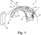
- FIG. 1 different views of a hearing aid device 2 according to the invention is illustrated in Fig. 1 .
- Fig. 1 illustrates schematically a cross-sectional view of a hearing aid device 2 according to the invention.
- the hearing aid device is a BTE hearing aid device 2 comprising a housing 4 with a microphone member 22, an amplifier 24 and a receiver 26.
- a hook 6 is mechanically attached to the housing 4.
- the hook 6 has an upper side 18, a lower side 16 and a distal end 28.
- the distal end 28 is configured to receive an ear mould (see Fig. 5 b) .
- the hook 6 is provided with a through-going bore 40 through which air-borne acoustic sound is transferred from the receiver 26 to the ear of the user via the ear mould.
- the antenna 20 extends along the upper side 18 of the hook 6.
- the antenna is embedded (e.g. by a moulding process) into the wall 124 of the hook 6.
- the antenna 20 is required in order to perform wireless communication with an external device 44 (e.g. a mobile phone).
- the hearing aid devices 2 may be configured to communicate wirelessly by using any wireless technology, however, it may be an advantage to apply a wireless technology standard for exchanging data over short distances such as Bluetooth applying short-wavelength radio transmissions in the ISM band from 2400-2480 MHz.
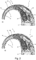
- Fig. 2 illustrates two schematically views of a hearing aid devices 2 according to the invention.
- Fig. 2 a is a cross-sectional view of a BTE hearing aid device 2 comprising a relative long antenna 20 that is embedded into wall 124 of the hook 6.
- the hearing aid device 2 corresponds basically to the one shown in Fig. 1 and it comprises a housing 4 with a microphone member 22, an amplifier 24, a receiver 26 and a hook 6 that is mechanically attached to the housing 4.
- the hook 6 has an upper side 18; a lower side 16 and a distal end 28 that is open and is configured to receive an ear mould (see Fig. 5 b) .
- the hook 6 is provided with a through-going bore 40 for transferring air-borne acoustic sound from the receiver 26 to the ear of the user via the ear mould.
- Fig. 2 b is a cross-sectional view of another BTE hearing aid device 2 comprising a relative short antenna 10 that is embedded into the wall 124 of the hook 6.
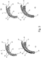
- Fig. 3 illustrates schematically cross-sectional views of four different hooks 6 according to the invention.
- the hooks 6 are configured to be used in BTE hearing aid devices 2 like the ones illustrated in Fig. 2 .
- the hooks 6 comprise an upper side 18 (that is concave in Fig. 3 ) and a lower side 16 (that is convex in Fig. 3 ).
- the hooks 6 have a proximal end 36 provided with a connection body 46 configured to be inserted into a housing of a BTE hearing aid like illustrated in Fig. 2 .
- the hooks 6 moreover comprise a distal end 28 configured to receive an ear mould (see Fig. 5 b) .
- each of the hooks 6 are provided with a through-going bore 40.
- Fig. 3 a illustrates a first hook 6 provided with a long, thin rod-shaped antenna 20 extending along the periphery of the upper side 18 of the hook 6.
- the antenna 20 comprises a protruding member 48 that protrudes from the proximal end 36 of the hook 6.
- the protruding member 48 is configured to be connected to the housing of a BTE hearing aid device.
- Fig. 3 b illustrates a second hook 6 provided with a short, flat antenna 10 that extends along the periphery of the upper side 18 of the hook 6.
- the antenna 20 comprises a protruding member 48 that protrudes from the proximal end 36 of the hook 6.
- the protruding member 48 is adapted to be connected to the housing of a BTE hearing aid device.
- Fig. 3 c illustrates a third hook 6 provided with a long, thin and flat antenna 20 that extends along the periphery of the upper side 18 of the hook 6.
- the antenna 20 comprises a protruding member 48 configured for connection with the housing of a BTE hearing aid device.
- Fig. 3 d illustrates a fourth hook 6 provided with a short rod-shaped antenna 10 that extends along the periphery of the upper side 18 of the hook 6.
- the antenna 20 has a protruding member 48 that protrudes from the proximal end 36 of the hook 6 and that is configured to be connected with the housing of a BTE hearing aid device.
- the antennas 10, 20 may be arranged within the hooks 6 during the manufacture of the hooks (e.g. by means of injection moulding). It is also possible to attach the antenna 10, 20 within the hook 6 afterwards e.g. by means of a mechanical attachment, gluing or by applying another suitable attachment method.
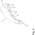
- Fig. 4 illustrates schematically a perspective view of a hook 6 of a hearing aid device according to the invention.
- the hook 6 is provided with a recess 56 configured to receive an antenna 20.
- the recess 56 extends from the distal end 28 of the hook 6 to the proximal end 35 of the hook 6.
- a basically cylindrical connection member 46 is provided at the proximal end 35 of the hook 6.
- An antenna 20 is indicated by a dotted line.
- Three ribs 58 are provided along the recess 56. The ribs 58 are configured to keep the antenna 20 in place within the recess 56.
- Fig. 5 a illustrates a perspective view of a BTE hearing aid device 2 according to the invention.
- the BTE hearing aid device 2 comprises a housing 4 and a hook 6 having a distal end 28 configured to receive an ear mould 66 (see Fig. 5 b) .
- An add on part 4.1 is shown connected to the housing 4.
- the add on part 4.1 may comprise a radio transceiver means or may comprise direct audio input connection means adapted to be connected to a wired audio source.
- the add on device may utilize the antenna of the hearing aid such that the add on device may be kept at a limited size.
- Fig. 5 b) illustrates a perspective view of the BTE hearing aid device 2 shown in Fig. 5 a) .
- a tube 60 is attached to the distal end 28 of the hook 6.
- the tube 60 is configured to transfer acoustic sound from the receiver within the housing 4 of the BTE hearing aid device 2.
- An ear mould 66 having a ventilation opening 64 and a sound outlet 62 is attached to the distal end of the tube 60. Air-borne acoustic sound from the receiver is transferred to ear of the user of the hearing aid device 2 through the sound outlet 62, when the ear mould 66 is arranged in the ear of the user.
- the antenna is not visible in Fig. 5 since it extends within the hook 6.
Landscapes
- Engineering & Computer Science (AREA)
- Computer Networks & Wireless Communication (AREA)
- Health & Medical Sciences (AREA)
- General Health & Medical Sciences (AREA)
- Neurosurgery (AREA)
- Otolaryngology (AREA)
- Physics & Mathematics (AREA)
- Acoustics & Sound (AREA)
- Signal Processing (AREA)
- Support Of Aerials (AREA)
- Details Of Aerials (AREA)
- Headphones And Earphones (AREA)
Description
- The present invention generally relates to a hearing aid device. The invention more particularly relates to a hearing aid device that is configured to communicate wirelessly with an external device.
- Recent hearing aid devices are adapted for communicating wirelessly with external devices. It is known to configure a hearing aid device to transmit a wireless signal to a corresponding hearing aid device (arranged in the other ear) in order to simultaneously change e.g. background settings of two hearings aid devices arranged in the both ears of a user.
-
US 2010/321269 A1 discloses a hearing aid comprising a casing and a sound tube providing both an ear hooking function. The receiver is located in the casing of the hearing aid. -
US 2013/223664 A1 discloses a hearing aid comprising an ear hook and an antenna located in the ear hook. The receiver is also located in said ear hook. - It is also known to use wireless technology standards for exchanging data over short distances by using short-wavelength radio transmissions, such as Bluetooth applying the ISM band from 2400-2480 MHz.
- When hearing aid device has to be configured to perform wireless communication there are a number of specific requirements to be considered, such as the size and position of the antenna.
- Thus, there is need for a hearing aid device that makes it possible to provide effective wireless communication with an external device.
- It is an object of the present invention to provide an effective way of arranging an antenna within a hearing aid device and to provide a hearing aid device capable of providing effective wireless communication with an external device.
- The object of the present invention can be achieved by a hearing aid device as defined in claim 1. Preferred embodiments are defined in the dependent sub claims and explained in the following description and illustrated in the accompanying drawings.
- The hearing aid device according to the invention is a hearing aid device configured to communicate wirelessly with an external device, where the hearing aid device comprises a housing with a microphone and an amplifier, where the hearing aid device further comprises an antenna and
a hook provided with a through-going bore configured to deliver air-borne sound acoustically from a receiver in the housing to an ear mould for dome via a tube connected to the hook, the tube configured to be attached to the distal end of the hook and the antenna extends along a portion of the hook and that the antenna is embedded into the wall of the hook. - Such hearing aid device makes it possible to provide effective wireless communication with an external device. Moreover it is possible to arrange the antenna within a hearing aid device in a manner that facilitates effective wireless communication with an external device.
- The hearing aid device according to the invention is a hearing aid device configured to communicate wirelessly with an external device. The external device may in principle be any suitable device e.g. a mobile phone, a computer, another hearing aid, a remote control, a wireless relay device adapted to advance an audio signal from another communication application, or the like.
- The hearing aid device may be configured to communicate wirelessly by using any wireless technology, however, it may be an advantage to use a wireless technology standard for exchanging data over short distances by using short-wavelength radio transmissions, e.g. Bluetooth applying the ISM band from 2400-2480 MHz.
- The hearing aid device comprises a housing (which also may be referred to as a casing) with a microphone and an amplifier.
- The hearing aid device may comprise several microphones and the microphone(s) may be of any suitable type.
- The amplifier may be of any suitable type.
- It may be preferred that the housing is configured to receive a battery for delivery of energy to the hearing aid device.
- The antenna may be any suitable type of antenna made in any suitable material and having any suitable form.
- The hearing aid device may be a behind-the-ear (BTE) hearing aid device by way of example.
- In the present context, a "hearing aid device" refers to a device, such as e.g. a hearing aid, a listening device or an active ear-protection device, which is adapted to improve, augment and/or protect the hearing capability of a user by receiving acoustic signals from the user's surroundings, generating corresponding audio signals, possibly modifying the audio signals and providing the possibly modified audio signals as audible signals to at least one of the user's ears.
- A "hearing aid device" further refers to a device such as an earphone or a headset adapted to receive audio signals electronically, possibly modifying the audio signals and providing the possibly modified audio signals as audible signals to at least one of the user's ears. Such audible signals are provided in the form of acoustic signals radiated into the user's outer ears.
- A hearing aid device may be configured to be worn in any known way, e.g. as a unit arranged behind the ear with a tube leading air-borne acoustic signals into the ear canal. A hearing device may comprise a single unit or several units communicating electronically with each other.
- More generally, a hearing aid device comprises an input transducer for receiving an acoustic signal from a user's surroundings and providing a corresponding input audio signal and/or a receiver for electronically receiving an input audio signal, a signal processing circuit for processing the input audio signal and an output means for providing an audible signal to the user in dependence on the processed audio signal. Some hearing aid devices may comprise multiple input transducers, e.g. for providing direction-dependent audio signal processing. In some hearing aid devices, the receiver may be a wireless receiver. In some hearing aid devices, the receiver may be e.g. an input amplifier for receiving a wired signal. In some hearing aid devices, an amplifier may constitute the signal processing circuit. In some hearing aid devices, the output means may comprise an output transducer, such as e.g. a loudspeaker for providing an air-borne acoustic signal.
- It is an advantage that the antenna extends along a portion of the hook and that the antenna is embedded into the wall of the hook. Hereby it is possible to provide a reliable antenna that is secured to the wall of the hook.
- It may be beneficial that the antenna comprises several separate antenna members that are electrically connected to each other to form one interconnected antenna.
- In this way it is possible to have an antenna that extends through several members that are configured to be attached to each other and to be detached from each other. This option provides great design freedom.
- The connections between adjacent antenna members may be of any suitable plug or type of connection
- It may be an advantage that the antenna is provided in a recess in the hook.
- Hereby a simple and reliable attachment of the antenna to the hook can be provided.
- It may be an advantage that the antenna is provided in a recess provided in the outer surface of the hook. Hereby the mounting of the antenna into the recess is eased.
- It may beneficial that the hearing aid device comprises a support arm configured to support and fixedly secure the antenna to the hook. Such construction is easy to use and provides optimum access for inspection of the antenna.
- It may be an advantage that the antenna is provided as a thin film.
- It may be preferred to provide the antenna with a coating, e.g. a protective coating.
- The invention will become more fully understood from the detailed description given herein below. The accompanying drawings are given by way of illustration only, and thus, they are not limitative of the present invention. In the accompanying drawings:
- Fig. 1
- shows schematically a cross-sectional view of a hearing aid device according to the invention;
- Fig. 2 a)
- shows a cross-sectional view of a BTE hearing aid device according to the invention;
- Fig. 2 a)
- shows a cross-sectional view of another BTE hearing aid device according to the invention;
- Fig. 3
- shows schematically cross-sectional views of four different hooks according to the invention;
- Fig. 4
- shows schematically a perspective view of a hook of a hearing aid device according to the invention;
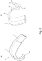
- Fig. 5 a)
- shows a perspective view of a BTE hearing aid device according to the invention;
- Fig. 5 b)
- shows another perspective view of the BTE hearing aid device shown in
Fig. 5 a) ; - Referring now in detail to the drawings for the purpose of illustrating preferred embodiments of the present invention, different views of a
hearing aid device 2 according to the invention is illustrated inFig. 1 . -
Fig. 1 illustrates schematically a cross-sectional view of ahearing aid device 2 according to the invention. The hearing aid device is a BTEhearing aid device 2 comprising ahousing 4 with amicrophone member 22, anamplifier 24 and areceiver 26. Ahook 6 is mechanically attached to thehousing 4. - The
hook 6 has anupper side 18, alower side 16 and adistal end 28. Thedistal end 28 is configured to receive an ear mould (seeFig. 5 b) . Thehook 6 is provided with a through-goingbore 40 through which air-borne acoustic sound is transferred from thereceiver 26 to the ear of the user via the ear mould. - The
antenna 20 extends along theupper side 18 of thehook 6. The antenna is embedded (e.g. by a moulding process) into thewall 124 of thehook 6. Theantenna 20 is required in order to perform wireless communication with an external device 44 (e.g. a mobile phone). - The
hearing aid devices 2 may be configured to communicate wirelessly by using any wireless technology, however, it may be an advantage to apply a wireless technology standard for exchanging data over short distances such as Bluetooth applying short-wavelength radio transmissions in the ISM band from 2400-2480 MHz. -
Fig. 2 illustrates two schematically views of ahearing aid devices 2 according to the invention.Fig. 2 a) is a cross-sectional view of a BTEhearing aid device 2 comprising a relativelong antenna 20 that is embedded intowall 124 of thehook 6. - The
hearing aid device 2 corresponds basically to the one shown inFig. 1 and it comprises ahousing 4 with amicrophone member 22, anamplifier 24, areceiver 26 and ahook 6 that is mechanically attached to thehousing 4. - The
hook 6 has anupper side 18; alower side 16 and adistal end 28 that is open and is configured to receive an ear mould (seeFig. 5 b) . Thehook 6 is provided with a through-goingbore 40 for transferring air-borne acoustic sound from thereceiver 26 to the ear of the user via the ear mould. -
Fig. 2 b) is a cross-sectional view of another BTEhearing aid device 2 comprising a relativeshort antenna 10 that is embedded into thewall 124 of thehook 6. The only difference between the twohearing aid devices 2 shown inFig. 2 a) and Fig. 2 b) is the length of theantennas -
Fig. 3 illustrates schematically cross-sectional views of fourdifferent hooks 6 according to the invention. Thehooks 6 are configured to be used in BTEhearing aid devices 2 like the ones illustrated inFig. 2 . - The
hooks 6 comprise an upper side 18 (that is concave inFig. 3 ) and a lower side 16 (that is convex inFig. 3 ). Thehooks 6 have aproximal end 36 provided with aconnection body 46 configured to be inserted into a housing of a BTE hearing aid like illustrated inFig. 2 . Thehooks 6 moreover comprise adistal end 28 configured to receive an ear mould (seeFig. 5 b) . Besides, each of thehooks 6 are provided with a through-goingbore 40. -
Fig. 3 a) illustrates afirst hook 6 provided with a long, thin rod-shapedantenna 20 extending along the periphery of theupper side 18 of thehook 6. Theantenna 20 comprises a protrudingmember 48 that protrudes from theproximal end 36 of thehook 6. The protrudingmember 48 is configured to be connected to the housing of a BTE hearing aid device. -
Fig. 3 b) illustrates asecond hook 6 provided with a short,flat antenna 10 that extends along the periphery of theupper side 18 of thehook 6. Theantenna 20 comprises a protrudingmember 48 that protrudes from theproximal end 36 of thehook 6. The protrudingmember 48 is adapted to be connected to the housing of a BTE hearing aid device. -
Fig. 3 c) illustrates athird hook 6 provided with a long, thin andflat antenna 20 that extends along the periphery of theupper side 18 of thehook 6. Theantenna 20 comprises a protrudingmember 48 configured for connection with the housing of a BTE hearing aid device. -
Fig. 3 d) illustrates afourth hook 6 provided with a short rod-shapedantenna 10 that extends along the periphery of theupper side 18 of thehook 6. Theantenna 20 has a protrudingmember 48 that protrudes from theproximal end 36 of thehook 6 and that is configured to be connected with the housing of a BTE hearing aid device. - The
antennas hooks 6 during the manufacture of the hooks (e.g. by means of injection moulding). It is also possible to attach theantenna hook 6 afterwards e.g. by means of a mechanical attachment, gluing or by applying another suitable attachment method. -
Fig. 4 illustrates schematically a perspective view of ahook 6 of a hearing aid device according to the invention. Thehook 6 is provided with arecess 56 configured to receive anantenna 20. Therecess 56 extends from thedistal end 28 of thehook 6 to the proximal end 35 of thehook 6. A basicallycylindrical connection member 46 is provided at the proximal end 35 of thehook 6. - An
antenna 20 is indicated by a dotted line. Threeribs 58 are provided along therecess 56. Theribs 58 are configured to keep theantenna 20 in place within therecess 56. -
Fig. 5 a) illustrates a perspective view of a BTEhearing aid device 2 according to the invention. The BTEhearing aid device 2 comprises ahousing 4 and ahook 6 having adistal end 28 configured to receive an ear mould 66 (seeFig. 5 b) . An add on part 4.1 is shown connected to thehousing 4. The add on part 4.1 may comprise a radio transceiver means or may comprise direct audio input connection means adapted to be connected to a wired audio source. The add on device may utilize the antenna of the hearing aid such that the add on device may be kept at a limited size. -
Fig. 5 b) illustrates a perspective view of the BTEhearing aid device 2 shown inFig. 5 a) . Atube 60 is attached to thedistal end 28 of thehook 6. Thetube 60 is configured to transfer acoustic sound from the receiver within thehousing 4 of the BTEhearing aid device 2. Anear mould 66 having aventilation opening 64 and asound outlet 62 is attached to the distal end of thetube 60. Air-borne acoustic sound from the receiver is transferred to ear of the user of thehearing aid device 2 through thesound outlet 62, when theear mould 66 is arranged in the ear of the user. - The antenna is not visible in
Fig. 5 since it extends within thehook 6. -
- 2 -
- Hearing aid device
- 4 -
- Housing
- 4.1 -
- add on device
- 6 -
- Hook
- 10 -
- Antenna
- 14 -
- Battery
- 16 -
- Lower side
- 18 -
- Upper side
- 20 -
- Antenna
- 22 -
- Microphone
- 24 -
- Amplifier
- 26 -
- Receiver
- 28 -
- End
- 36 -
- Proximal end
- 40 -
- Bore
- 44 -
- External device
- 46 -
- Connection body
- 48 -
- Protruding portion
- 50 -
- Ring member
- 52 -
- Connection member
- 54 -
- Coaxial sleeve
- 56 -
- Recess
- 58 -
- Rib
- 60 -
- Tube
- 62 -
- Sound outlet
- 64 -
- Ventilation opening
- 66 -
- Ear mould
- 124 -
- Wall
Claims (8)
- A hearing aid device (2) configured to communicate wirelessly with an external device (44) where the hearing aid device (2) comprises a housing (4) with a microphone (22) and an amplifier (24), where the hearing aid device (2) further comprises an antenna (10, 20) and:further comprising a hook (6) provided with a through-going bore configured to deliver air-borne sound acoustically from a receiver (26) in the housing (4) to an ear mould (66) or dome via a tube (60) connected to the hook,the tube (60) configured to be attached to the distal end (28) of the hook (6), whereinthe antenna (10, 20) extends along a portion of the hook (6) and that the antenna (20) is embedded into the wall (124) of the hook (6).
- A hearing aid device (2) according to claim 1, wherein the antenna (20) has a protruding member (48) that protrudes from the proximal end (36) of the hook (6) and that is configured to be connected with the housing (4).
- A hearing aid device (2) according to claim 1 or 2, wherein the antenna (10, 20) comprises several separate antenna members (20, 20', 20", 10, 10') that are electrically connected to each other to form one interconnected antenna (20, 20', 20", 10, 10').
- A hearing aid device (2) according to claim 3, wherein the housing (4) comprises at least one of the antenna members (10, 20)
- A hearing aid device (2) according to one of the preceding claims, wherein the antenna (10, 20) is provided in a recess (56) in the hook (6).
- A hearing aid device (2) according to one of the preceding claims, wherein the hearing aid device comprises several members that are configured to be attached to each other and to be detached from each other, wherein the antenna extends through several of these members.
- A hearing aid device (2) according to one of the preceding claims, wherein the hearing aid device (2) is configured to communicate using the Bluetooth protocol.
- A hearing aid device (2) according to one of the preceding claims, wherein the antenna (10, 20) is configured to operate at 2400 - 2480 MHZ.
Priority Applications (2)
| Application Number | Priority Date | Filing Date | Title |
|---|---|---|---|
| EP17161852.3A EP3200480B1 (en) | 2013-09-19 | 2013-09-19 | Hearing aid device with integrated antenna |
| DK17161852.3T DK3200480T3 (en) | 2013-09-19 | 2013-09-19 | HEARING DEVICE WITH INTEGRATED ANTENNA |
Applications Claiming Priority (2)
| Application Number | Priority Date | Filing Date | Title |
|---|---|---|---|
| EP17161852.3A EP3200480B1 (en) | 2013-09-19 | 2013-09-19 | Hearing aid device with integrated antenna |
| EP13185193.3A EP2852181B1 (en) | 2013-09-19 | 2013-09-19 | Hearing aid device with integrated antenna |
Related Parent Applications (2)
| Application Number | Title | Priority Date | Filing Date |
|---|---|---|---|
| EP13185193.3A Division-Into EP2852181B1 (en) | 2013-09-19 | 2013-09-19 | Hearing aid device with integrated antenna |
| EP13185193.3A Division EP2852181B1 (en) | 2013-09-19 | 2013-09-19 | Hearing aid device with integrated antenna |
Publications (2)
| Publication Number | Publication Date |
|---|---|
| EP3200480A1 EP3200480A1 (en) | 2017-08-02 |
| EP3200480B1 true EP3200480B1 (en) | 2020-03-11 |
Family
ID=49209281
Family Applications (2)
| Application Number | Title | Priority Date | Filing Date |
|---|---|---|---|
| EP17161852.3A Active EP3200480B1 (en) | 2013-09-19 | 2013-09-19 | Hearing aid device with integrated antenna |
| EP13185193.3A Not-in-force EP2852181B1 (en) | 2013-09-19 | 2013-09-19 | Hearing aid device with integrated antenna |
Family Applications After (1)
| Application Number | Title | Priority Date | Filing Date |
|---|---|---|---|
| EP13185193.3A Not-in-force EP2852181B1 (en) | 2013-09-19 | 2013-09-19 | Hearing aid device with integrated antenna |
Country Status (4)
| Country | Link |
|---|---|
| US (4) | US9491554B2 (en) |
| EP (2) | EP3200480B1 (en) |
| CN (1) | CN104469644B (en) |
| DK (2) | DK3200480T3 (en) |
Families Citing this family (19)
| Publication number | Priority date | Publication date | Assignee | Title |
|---|---|---|---|---|
| KR102092857B1 (en) * | 2013-10-25 | 2020-03-25 | 삼성전자주식회사 | Leaky-wave antenna for hearing device |
| KR102244609B1 (en) | 2015-04-28 | 2021-04-26 | 삼성전자주식회사 | Mounting structure of electronic device for shutting off power and case, electronic device therof |
| US10321248B2 (en) * | 2015-06-03 | 2019-06-11 | Gn Hearing A/S | Hearing device shell with guide structure |
| EP3101917B1 (en) * | 2015-06-03 | 2017-10-11 | GN Resound A/S | Hearing aid configuration detection |
| US9661426B2 (en) * | 2015-06-22 | 2017-05-23 | Gn Hearing A/S | Hearing aid having combined antennas |
| US20170188163A1 (en) * | 2015-12-28 | 2017-06-29 | Jay Rabel | Hearing assistance device earhook and sound tube antennas |
| US10412514B2 (en) * | 2016-04-22 | 2019-09-10 | Starkey Laboratories, Inc. | Hearing device antenna with optimized orientation |
| EP3267696A1 (en) * | 2016-07-08 | 2018-01-10 | Oticon Medical A/S | Hearing aid comprising a locking mechanism |
| DE102017207528A1 (en) * | 2017-05-04 | 2018-11-08 | Sivantos Pte. Ltd. | Module for installation in a hearing aid |
| USD870697S1 (en) * | 2017-08-01 | 2019-12-24 | Wei Zhang | Bluetooth headset |
| US10893349B2 (en) * | 2018-03-30 | 2021-01-12 | Audio-Technica U.S., Inc. | Wireless microphone comprising a plurality of antennas |
| US11082781B2 (en) * | 2019-08-08 | 2021-08-03 | Sonova Ag | Ear piece with active vent control |
| EP3806493B1 (en) * | 2019-10-11 | 2023-07-19 | GN Hearing A/S | A hearing device having a magnetic induction coil |
| CN110585596A (en) * | 2019-10-11 | 2019-12-20 | 苏州智听信息科技有限公司 | Artificial cochlea stabilizing device |
| EP3836568A1 (en) * | 2019-12-10 | 2021-06-16 | Oticon Medical A/S | Bone conduction hearing aid device having patch antenna with leads arranged betweeen antenna layers |
| TWI786486B (en) * | 2020-12-10 | 2022-12-11 | 仁寶電腦工業股份有限公司 | Hearing aid device |
| US20240089646A1 (en) * | 2021-01-27 | 2024-03-14 | New Audio LLC | Wireless earpiece with external antenna features and related technology |
| WO2023021357A1 (en) | 2021-08-16 | 2023-02-23 | Cochlear Limited | Devices with integrated concave coils |
| CN116456238B (en) * | 2023-03-28 | 2025-11-28 | 德乐迈科技(北京)有限公司 | Earphone with external antenna and audio playing method |
Family Cites Families (19)
| Publication number | Priority date | Publication date | Assignee | Title |
|---|---|---|---|---|
| US5761319A (en) * | 1996-07-16 | 1998-06-02 | Avr Communications Ltd. | Hearing instrument |
| US6748094B1 (en) | 2000-03-03 | 2004-06-08 | Advanced Bionics Corporation | Connector system for BTE hearing devices |
| US7570777B1 (en) * | 2004-01-13 | 2009-08-04 | Step Labs, Inc. | Earset assembly |
| US7443991B2 (en) * | 2004-03-31 | 2008-10-28 | Siemens Audiologische Technik Gmbh | ITE hearing aid for binaural hearing assistance |
| DE102005046169A1 (en) * | 2005-09-27 | 2007-04-05 | Siemens Audiologische Technik Gmbh | Hearing aid with an antenna |
| US7548211B2 (en) * | 2006-03-30 | 2009-06-16 | Phonak Ag | Wireless audio signal receiver device for a hearing instrument |
| US8094859B2 (en) * | 2006-12-14 | 2012-01-10 | Sharp Kabushiki Kaisha | Dipole antenna device, earphone antenna device, and wireless communication terminal device connected to the device |
| EP2147570A1 (en) * | 2007-05-24 | 2010-01-27 | Phonak AG | Hearing device with rf communication |
| US8934984B2 (en) * | 2007-05-31 | 2015-01-13 | Cochlear Limited | Behind-the-ear (BTE) prosthetic device with antenna |
| WO2009098858A1 (en) * | 2008-02-04 | 2009-08-13 | Panasonic Corporation | Behind-the-ear radio device |
| US9295848B2 (en) * | 2008-03-28 | 2016-03-29 | Cochlear Limited | Antenna for behind-the-ear (BTE) devices |
| FR2931076B1 (en) * | 2008-05-15 | 2010-06-25 | Neurelec | IMPLANTABLE SUB-CUTANE DEVICE |
| KR101017673B1 (en) * | 2008-07-18 | 2011-02-25 | 주식회사 에이스테크놀로지 | Built-in antenna for the headset |
| DK2229009T3 (en) * | 2009-03-09 | 2014-02-03 | Oticon As | Hearing aid |
| EP2468013B1 (en) * | 2009-08-17 | 2014-01-08 | Phonak AG | Attachment of a hook to a hearing device |
| EP2499841B1 (en) * | 2009-11-13 | 2015-09-23 | Advanced Bionics AG | Accessory adapter for cochlear implant system providing simultaneous t-mic and external audio input |
| CN202488708U (en) * | 2011-12-16 | 2012-10-10 | 江苏贝泰福医疗科技有限公司 | Digital hearing-aid |
| US9319807B2 (en) * | 2012-02-28 | 2016-04-19 | Cochlear Limited | Device with combined antenna and transducer |
| DK201270410A (en) * | 2012-07-06 | 2014-01-07 | Gn Resound As | BTE hearing aid with an antenna partition plane |
-
2013
- 2013-09-19 EP EP17161852.3A patent/EP3200480B1/en active Active
- 2013-09-19 DK DK17161852.3T patent/DK3200480T3/en active
- 2013-09-19 DK DK13185193.3T patent/DK2852181T3/en active
- 2013-09-19 EP EP13185193.3A patent/EP2852181B1/en not_active Not-in-force
-
2014
- 2014-09-19 CN CN201410484441.3A patent/CN104469644B/en active Active
- 2014-09-19 US US14/491,326 patent/US9491554B2/en active Active
-
2016
- 2016-10-06 US US15/286,715 patent/US10327079B2/en active Active
-
2019
- 2019-05-01 US US16/400,892 patent/US11012794B2/en active Active
-
2021
- 2021-04-13 US US17/229,387 patent/US11483668B2/en active Active
Non-Patent Citations (1)
| Title |
|---|
| None * |
Also Published As
| Publication number | Publication date |
|---|---|
| EP2852181B1 (en) | 2017-10-18 |
| DK3200480T3 (en) | 2020-04-27 |
| US11012794B2 (en) | 2021-05-18 |
| US20150078599A1 (en) | 2015-03-19 |
| US20210235205A1 (en) | 2021-07-29 |
| CN104469644A (en) | 2015-03-25 |
| DK2852181T3 (en) | 2017-12-11 |
| US20190261101A1 (en) | 2019-08-22 |
| EP3200480A1 (en) | 2017-08-02 |
| CN104469644B (en) | 2019-11-12 |
| US10327079B2 (en) | 2019-06-18 |
| US9491554B2 (en) | 2016-11-08 |
| US20170086000A1 (en) | 2017-03-23 |
| US11483668B2 (en) | 2022-10-25 |
| EP2852181A1 (en) | 2015-03-25 |
Similar Documents
| Publication | Publication Date | Title |
|---|---|---|
| US11483668B2 (en) | Hearing aid device with integrated antenna | |
| US10694276B2 (en) | In-ear headphone | |
| US10827289B2 (en) | Antenna unit | |
| WO2009098858A1 (en) | Behind-the-ear radio device | |
| US8903309B2 (en) | True stereo wireless headset and method | |
| CN104469584A (en) | Bluetooth earplugs | |
| EP3324644B1 (en) | A wireless hearing device with stabilizing guide unit between tragus and antitragus | |
| CN101933340A (en) | In-ear headphones and headsets | |
| EP4340388A1 (en) | An earphone and a method of performing a command by an earphone | |
| EP3226582A1 (en) | Hearing device comprising modular engagement means | |
| EP2036393B1 (en) | Device in a headset | |
| JP2019536387A (en) | Bidirectional communication system and method of using the same | |
| US11044564B2 (en) | Hearing systems and methods for operating a hearing system | |
| US11399244B2 (en) | Hearing instrument | |
| US20170325036A1 (en) | Hearing device | |
| US20050190937A1 (en) | Pocket hearing aid | |
| EP4362499A1 (en) | A hearing aid with improved suspension | |
| EP1674057B1 (en) | Hearing protection device and use of such a device | |
| CN115580801A (en) | Earphone and earphone box assembly | |
| KR101860523B1 (en) | A Hearing Device Having a Structure of a Separated Algorism Processing Module | |
| WO2020116253A1 (en) | Electroacoustic transducer and acoustic device | |
| EP4513898A1 (en) | An ear dome for a hearing device | |
| EP4615007A1 (en) | In-the-ear hearing aid with antenna |
Legal Events
| Date | Code | Title | Description |
|---|---|---|---|
| PUAI | Public reference made under article 153(3) epc to a published international application that has entered the european phase |
Free format text: ORIGINAL CODE: 0009012 |
|
| STAA | Information on the status of an ep patent application or granted ep patent |
Free format text: STATUS: THE APPLICATION HAS BEEN PUBLISHED |
|
| AC | Divisional application: reference to earlier application |
Ref document number: 2852181 Country of ref document: EP Kind code of ref document: P |
|
| AK | Designated contracting states |
Kind code of ref document: A1 Designated state(s): AL AT BE BG CH CY CZ DE DK EE ES FI FR GB GR HR HU IE IS IT LI LT LU LV MC MK MT NL NO PL PT RO RS SE SI SK SM TR |
|
| STAA | Information on the status of an ep patent application or granted ep patent |
Free format text: STATUS: REQUEST FOR EXAMINATION WAS MADE |
|
| STAA | Information on the status of an ep patent application or granted ep patent |
Free format text: STATUS: EXAMINATION IS IN PROGRESS |
|
| 17P | Request for examination filed |
Effective date: 20180202 |
|
| RBV | Designated contracting states (corrected) |
Designated state(s): AL AT BE BG CH CY CZ DE DK EE ES FI FR GB GR HR HU IE IS IT LI LT LU LV MC MK MT NL NO PL PT RO RS SE SI SK SM TR |
|
| 17Q | First examination report despatched |
Effective date: 20180306 |
|
| RIC1 | Information provided on ipc code assigned before grant |
Ipc: H01Q 1/40 20060101ALI20190528BHEP Ipc: H01Q 1/27 20060101ALI20190528BHEP Ipc: H04R 25/00 20060101AFI20190528BHEP |
|
| GRAP | Despatch of communication of intention to grant a patent |
Free format text: ORIGINAL CODE: EPIDOSNIGR1 |
|
| STAA | Information on the status of an ep patent application or granted ep patent |
Free format text: STATUS: GRANT OF PATENT IS INTENDED |
|
| INTG | Intention to grant announced |
Effective date: 20190731 |
|
| GRAS | Grant fee paid |
Free format text: ORIGINAL CODE: EPIDOSNIGR3 |
|
| GRAA | (expected) grant |
Free format text: ORIGINAL CODE: 0009210 |
|
| STAA | Information on the status of an ep patent application or granted ep patent |
Free format text: STATUS: THE PATENT HAS BEEN GRANTED |
|
| AC | Divisional application: reference to earlier application |
Ref document number: 2852181 Country of ref document: EP Kind code of ref document: P |
|
| AK | Designated contracting states |
Kind code of ref document: B1 Designated state(s): AL AT BE BG CH CY CZ DE DK EE ES FI FR GB GR HR HU IE IS IT LI LT LU LV MC MK MT NL NO PL PT RO RS SE SI SK SM TR |
|
| REG | Reference to a national code |
Ref country code: GB Ref legal event code: FG4D |
|
| REG | Reference to a national code |
Ref country code: CH Ref legal event code: EP |
|
| REG | Reference to a national code |
Ref country code: AT Ref legal event code: REF Ref document number: 1244665 Country of ref document: AT Kind code of ref document: T Effective date: 20200315 |
|
| REG | Reference to a national code |
Ref country code: IE Ref legal event code: FG4D |
|
| REG | Reference to a national code |
Ref country code: DE Ref legal event code: R096 Ref document number: 602013066856 Country of ref document: DE |
|
| REG | Reference to a national code |
Ref country code: DK Ref legal event code: T3 Effective date: 20200426 |
|
| PG25 | Lapsed in a contracting state [announced via postgrant information from national office to epo] |
Ref country code: RS Free format text: LAPSE BECAUSE OF FAILURE TO SUBMIT A TRANSLATION OF THE DESCRIPTION OR TO PAY THE FEE WITHIN THE PRESCRIBED TIME-LIMIT Effective date: 20200311 Ref country code: FI Free format text: LAPSE BECAUSE OF FAILURE TO SUBMIT A TRANSLATION OF THE DESCRIPTION OR TO PAY THE FEE WITHIN THE PRESCRIBED TIME-LIMIT Effective date: 20200311 Ref country code: NO Free format text: LAPSE BECAUSE OF FAILURE TO SUBMIT A TRANSLATION OF THE DESCRIPTION OR TO PAY THE FEE WITHIN THE PRESCRIBED TIME-LIMIT Effective date: 20200611 |
|
| REG | Reference to a national code |
Ref country code: NL Ref legal event code: MP Effective date: 20200311 |
|
| PG25 | Lapsed in a contracting state [announced via postgrant information from national office to epo] |
Ref country code: SE Free format text: LAPSE BECAUSE OF FAILURE TO SUBMIT A TRANSLATION OF THE DESCRIPTION OR TO PAY THE FEE WITHIN THE PRESCRIBED TIME-LIMIT Effective date: 20200311 Ref country code: LV Free format text: LAPSE BECAUSE OF FAILURE TO SUBMIT A TRANSLATION OF THE DESCRIPTION OR TO PAY THE FEE WITHIN THE PRESCRIBED TIME-LIMIT Effective date: 20200311 Ref country code: HR Free format text: LAPSE BECAUSE OF FAILURE TO SUBMIT A TRANSLATION OF THE DESCRIPTION OR TO PAY THE FEE WITHIN THE PRESCRIBED TIME-LIMIT Effective date: 20200311 Ref country code: BG Free format text: LAPSE BECAUSE OF FAILURE TO SUBMIT A TRANSLATION OF THE DESCRIPTION OR TO PAY THE FEE WITHIN THE PRESCRIBED TIME-LIMIT Effective date: 20200611 Ref country code: GR Free format text: LAPSE BECAUSE OF FAILURE TO SUBMIT A TRANSLATION OF THE DESCRIPTION OR TO PAY THE FEE WITHIN THE PRESCRIBED TIME-LIMIT Effective date: 20200612 |
|
| REG | Reference to a national code |
Ref country code: LT Ref legal event code: MG4D |
|
| PG25 | Lapsed in a contracting state [announced via postgrant information from national office to epo] |
Ref country code: NL Free format text: LAPSE BECAUSE OF FAILURE TO SUBMIT A TRANSLATION OF THE DESCRIPTION OR TO PAY THE FEE WITHIN THE PRESCRIBED TIME-LIMIT Effective date: 20200311 |
|
| PG25 | Lapsed in a contracting state [announced via postgrant information from national office to epo] |
Ref country code: RO Free format text: LAPSE BECAUSE OF FAILURE TO SUBMIT A TRANSLATION OF THE DESCRIPTION OR TO PAY THE FEE WITHIN THE PRESCRIBED TIME-LIMIT Effective date: 20200311 Ref country code: IS Free format text: LAPSE BECAUSE OF FAILURE TO SUBMIT A TRANSLATION OF THE DESCRIPTION OR TO PAY THE FEE WITHIN THE PRESCRIBED TIME-LIMIT Effective date: 20200711 Ref country code: SK Free format text: LAPSE BECAUSE OF FAILURE TO SUBMIT A TRANSLATION OF THE DESCRIPTION OR TO PAY THE FEE WITHIN THE PRESCRIBED TIME-LIMIT Effective date: 20200311 Ref country code: CZ Free format text: LAPSE BECAUSE OF FAILURE TO SUBMIT A TRANSLATION OF THE DESCRIPTION OR TO PAY THE FEE WITHIN THE PRESCRIBED TIME-LIMIT Effective date: 20200311 Ref country code: SM Free format text: LAPSE BECAUSE OF FAILURE TO SUBMIT A TRANSLATION OF THE DESCRIPTION OR TO PAY THE FEE WITHIN THE PRESCRIBED TIME-LIMIT Effective date: 20200311 Ref country code: EE Free format text: LAPSE BECAUSE OF FAILURE TO SUBMIT A TRANSLATION OF THE DESCRIPTION OR TO PAY THE FEE WITHIN THE PRESCRIBED TIME-LIMIT Effective date: 20200311 Ref country code: LT Free format text: LAPSE BECAUSE OF FAILURE TO SUBMIT A TRANSLATION OF THE DESCRIPTION OR TO PAY THE FEE WITHIN THE PRESCRIBED TIME-LIMIT Effective date: 20200311 Ref country code: PT Free format text: LAPSE BECAUSE OF FAILURE TO SUBMIT A TRANSLATION OF THE DESCRIPTION OR TO PAY THE FEE WITHIN THE PRESCRIBED TIME-LIMIT Effective date: 20200805 |
|
| REG | Reference to a national code |
Ref country code: AT Ref legal event code: MK05 Ref document number: 1244665 Country of ref document: AT Kind code of ref document: T Effective date: 20200311 |
|
| REG | Reference to a national code |
Ref country code: DE Ref legal event code: R097 Ref document number: 602013066856 Country of ref document: DE |
|
| PLBE | No opposition filed within time limit |
Free format text: ORIGINAL CODE: 0009261 |
|
| STAA | Information on the status of an ep patent application or granted ep patent |
Free format text: STATUS: NO OPPOSITION FILED WITHIN TIME LIMIT |
|
| PG25 | Lapsed in a contracting state [announced via postgrant information from national office to epo] |
Ref country code: AT Free format text: LAPSE BECAUSE OF FAILURE TO SUBMIT A TRANSLATION OF THE DESCRIPTION OR TO PAY THE FEE WITHIN THE PRESCRIBED TIME-LIMIT Effective date: 20200311 Ref country code: ES Free format text: LAPSE BECAUSE OF FAILURE TO SUBMIT A TRANSLATION OF THE DESCRIPTION OR TO PAY THE FEE WITHIN THE PRESCRIBED TIME-LIMIT Effective date: 20200311 Ref country code: IT Free format text: LAPSE BECAUSE OF FAILURE TO SUBMIT A TRANSLATION OF THE DESCRIPTION OR TO PAY THE FEE WITHIN THE PRESCRIBED TIME-LIMIT Effective date: 20200311 |
|
| 26N | No opposition filed |
Effective date: 20201214 |
|
| PG25 | Lapsed in a contracting state [announced via postgrant information from national office to epo] |
Ref country code: PL Free format text: LAPSE BECAUSE OF FAILURE TO SUBMIT A TRANSLATION OF THE DESCRIPTION OR TO PAY THE FEE WITHIN THE PRESCRIBED TIME-LIMIT Effective date: 20200311 Ref country code: SI Free format text: LAPSE BECAUSE OF FAILURE TO SUBMIT A TRANSLATION OF THE DESCRIPTION OR TO PAY THE FEE WITHIN THE PRESCRIBED TIME-LIMIT Effective date: 20200311 |
|
| PG25 | Lapsed in a contracting state [announced via postgrant information from national office to epo] |
Ref country code: MC Free format text: LAPSE BECAUSE OF FAILURE TO SUBMIT A TRANSLATION OF THE DESCRIPTION OR TO PAY THE FEE WITHIN THE PRESCRIBED TIME-LIMIT Effective date: 20200311 |
|
| REG | Reference to a national code |
Ref country code: BE Ref legal event code: MM Effective date: 20200930 |
|
| PG25 | Lapsed in a contracting state [announced via postgrant information from national office to epo] |
Ref country code: LU Free format text: LAPSE BECAUSE OF NON-PAYMENT OF DUE FEES Effective date: 20200919 |
|
| PG25 | Lapsed in a contracting state [announced via postgrant information from national office to epo] |
Ref country code: BE Free format text: LAPSE BECAUSE OF NON-PAYMENT OF DUE FEES Effective date: 20200930 Ref country code: IE Free format text: LAPSE BECAUSE OF NON-PAYMENT OF DUE FEES Effective date: 20200919 |
|
| PG25 | Lapsed in a contracting state [announced via postgrant information from national office to epo] |
Ref country code: TR Free format text: LAPSE BECAUSE OF FAILURE TO SUBMIT A TRANSLATION OF THE DESCRIPTION OR TO PAY THE FEE WITHIN THE PRESCRIBED TIME-LIMIT Effective date: 20200311 Ref country code: MT Free format text: LAPSE BECAUSE OF FAILURE TO SUBMIT A TRANSLATION OF THE DESCRIPTION OR TO PAY THE FEE WITHIN THE PRESCRIBED TIME-LIMIT Effective date: 20200311 Ref country code: CY Free format text: LAPSE BECAUSE OF FAILURE TO SUBMIT A TRANSLATION OF THE DESCRIPTION OR TO PAY THE FEE WITHIN THE PRESCRIBED TIME-LIMIT Effective date: 20200311 |
|
| PG25 | Lapsed in a contracting state [announced via postgrant information from national office to epo] |
Ref country code: MK Free format text: LAPSE BECAUSE OF FAILURE TO SUBMIT A TRANSLATION OF THE DESCRIPTION OR TO PAY THE FEE WITHIN THE PRESCRIBED TIME-LIMIT Effective date: 20200311 Ref country code: AL Free format text: LAPSE BECAUSE OF FAILURE TO SUBMIT A TRANSLATION OF THE DESCRIPTION OR TO PAY THE FEE WITHIN THE PRESCRIBED TIME-LIMIT Effective date: 20200311 |
|
| REG | Reference to a national code |
Ref country code: CH Ref legal event code: U11 Free format text: ST27 STATUS EVENT CODE: U-0-0-U10-U11 (AS PROVIDED BY THE NATIONAL OFFICE) Effective date: 20251001 |
|
| PGFP | Annual fee paid to national office [announced via postgrant information from national office to epo] |
Ref country code: DE Payment date: 20250828 Year of fee payment: 13 Ref country code: DK Payment date: 20250827 Year of fee payment: 13 |
|
| PGFP | Annual fee paid to national office [announced via postgrant information from national office to epo] |
Ref country code: GB Payment date: 20250828 Year of fee payment: 13 |
|
| PGFP | Annual fee paid to national office [announced via postgrant information from national office to epo] |
Ref country code: FR Payment date: 20250828 Year of fee payment: 13 |
|
| PGFP | Annual fee paid to national office [announced via postgrant information from national office to epo] |
Ref country code: CH Payment date: 20251001 Year of fee payment: 13 |