EP3200643B1 - Wimpernformer - Google Patents
Wimpernformer Download PDFInfo
- Publication number
- EP3200643B1 EP3200643B1 EP14853861.4A EP14853861A EP3200643B1 EP 3200643 B1 EP3200643 B1 EP 3200643B1 EP 14853861 A EP14853861 A EP 14853861A EP 3200643 B1 EP3200643 B1 EP 3200643B1
- Authority
- EP
- European Patent Office
- Prior art keywords
- eyelashes
- edge
- curler
- blade
- eyelash
- Prior art date
- Legal status (The legal status is an assumption and is not a legal conclusion. Google has not performed a legal analysis and makes no representation as to the accuracy of the status listed.)
- Active
Links
Images

Classifications
-
- A—HUMAN NECESSITIES
- A45—HAND OR TRAVELLING ARTICLES
- A45D—HAIRDRESSING OR SHAVING EQUIPMENT; EQUIPMENT FOR COSMETICS OR COSMETIC TREATMENTS, e.g. FOR MANICURING OR PEDICURING
- A45D2/00—Hair-curling or hair-waving appliances ; Appliances for hair dressing treatment not otherwise provided for
- A45D2/48—Eyelash curlers; Eyebrow curlers
Definitions
- the present invention relates to an eyelash curler.
- An eyelash curler is a device, usually hand-operated, for curling eyelashes for cosmetic purposes.
- EP0081020A1 , EP2292116A1 , US2005/061347A1 disclose eyelash curlers.
- an eyelash curler according to claim 1.
- the curler is configured such that the upper and lower sections can be, or are, urged towards each other to effect clamping of the eyelashes between the upper and lower sections.
- the upper and lower sections are interconnected at proximal ends thereof via a hinge about which they can pivot to effect the clamping and release from clamping of the eyelashes.
- the hinge may be a living hinge which is resiliently deformable.
- the curler is configured such that the scraping of the or each edge along the top side is in a direction from a proximal end of the eyelashes to a distal end of the eyelashes. It is, however, also possible that the curler may be configured such that the scraping of the or each edge along the top side is in a direction from a distal to a proximal end of the eyelashes.
- the eyelash curler is a handheld device.
- the or each edge is movable axially relative to the support portion, whereby the support portion remains substantially stationary with respect to the lashes as the or each edge is scraped along said top side.
- the upper section comprises a support, preferably in the form of an arm, from which the or each edge is supported movably so as to be able to be scraped along said top side.
- the lower section comprises a support, preferably in the form of an arm, from which the support portion is supported. Preferably, the support portion is fixed relative to the lower section support.
- the upper section has a said edge which can be moved from a start position to an end position, whereby it is scraped along said top side, and thereafter returned to said start position such that movement thereof from the start position to the end position, whereby it is scraped along said top side, is repeatable.
- the edge may thus be movable in a reciprocating manner to curl the eyelashes.
- the edge is defined by a blade which is movably coupled to the support of the upper section.
- the blade may be coupled to the upper section support through an axial slot in that support, so as to be movable back and forth along the slot.
- the eyelash curler includes an actuator operable by at least one digit, e.g. a finger or thumb of a person's hand, whereby the movement of the said edge from the start position to the end position and the return of the said edge to the start position is effected.
- the upper section has plural said edges which can be scraped one-after-another along said top side.
- the upper section comprises an element which is configured with said edges arranged circumferentially therearound at spaced apart positions and in substantially parallel relation, and which is mounted to the support of the upper section to be rotatable about an axis which is substantially parallel to the edges.
- said element is manually rotatable.
- the curler is configured such that the rotation can be effected by finger or thumb.
- the rotatable element takes the form of a wheel.
- the rotatable element comprises radially outwardly projecting blades distal ends of which define the edges.
- the element is rotatable in a direction such that each blade is drawn along said top side in a direction from a proximal end to a distal end of each of the eyelashes.
- the curler comprises an actuator engaged with the rotatable element to effect rotation thereof.
- the actuator forms part of the upper section.
- the actuator is mounted to said support of the upper section.
- the actuator is rotatable and engaged with said element in a manner such that rotation of the actuator imparts rotation to the element.
- the actuator and element are intermeshed such that rotation of the actuator effects rotation of the element.
- the actuator may comprise radially outwardly projecting fins or paddles arranged so as to mesh with the blades of said element.
- the curler according to this embodiment may be configured such that said element can be rotated by being engaged directly by one or more digits on a person's hand.
- the curler is configured such that a section, rather than the entirety, of the eyelashes along a given eyelid is held between the upper and lower sections.
- the or each blade may be defined by a fin or paddle.
- the edge is relatively sharp.
- the eyelash support portion comprises a bed arranged such that a bottom side of the clamped eyelashes rests thereagainst.
- the bed is defined by a surface that is curved about an axis which is generally parallel to the edge(s) and thus defines a concavity which receives the clamped eyelashes.
- a method of curling eyelashes according to claim 14, wherein the eyelashes are clamped between said edge(s) and the support portion of a curler as defined above and one or more said edges is drawn along the topside of the eyelashes.
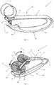
- FIG. 1 An eyelash curler 1 according to an embodiment of the present invention is illustrated in Figure 1 .
- the eyelash curler 1 is a handheld device which is manually operable to curl a person's eyelashes.
- the device 1 comprises opposed upper 10 and lower 20 sections and a living hinge 3 via which those sections are interconnected.
- Upper section 10 comprises an arm 12 projecting away from the living hinge 3, a distal end of the arm being configured with an axial slot 14 therethrough, and, received through the slot 14, an assembly comprising a downwardly projecting blade 16, in the form of a fin. defining an eyelash-engaging edge 17 which extends substantially perpendicular to the arm 12, and a ring member 18, attached at a lower end thereof to an upper end of the blade 16 via a narrow interconnection occupying the slot 14, the ring member 18 defining an actuator operable to draw the edge 17 along the top of a section of eyelashes to curl the eyelashes, as will be described in further detail later.
- the lower section 20 comprises an arm 22, which projects away from the living hinge 3, below and substantially parallel with the arm 12.
- the lower section 20 is configured, at a distal end of the arm 22, with an eyelash support portion, in the form of a bed 24 arranged to support an underside of the section of eyelashes as the blade 16 is drawn along them, the bed 24 being curved about an axis parallel to the edge 17 so as to be downwardly concave.
- the bed 24 provides a curved surface 25 against which the eyelashes rest during operation of the curler 1.
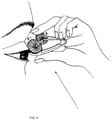
- the eyelash curler 1 referring to Figure 3 , is operated as follows.
- the person holds the curler 1 by its arms 12, 22, positioning it such that the person's eyelashes are received between the bed 24 and blade edge 17, and then urges the arms 12 and 22 towards each other, by pressing them between finger and thumb, so that the eyelashes are held, in a clamped manner, between the edge 17 and bed surface 25.
- the person can then again apply pressure to the arms 12 and 22, effecting clamping of the eyelashes between the blade 16 and bed 24, and draw the edge 17 along the topside of the eyelashes as previously described.
- the configuration and degree of curling can be controlled according to the number of cycles through which the curler 1 is put and the amount of clamping pressure the person imparts to the bed 24 and blade 16 (which pressure could be varied as the blade 16 moves from its start position to its end position).
- FIG. 2 An eyelash curler 1' according to a second preferred embodiment of the invention is shown in Figure 2 .
- the same reference numerals as have been used in respect of the first embodiment will be used to denote the same or corresponding features.
- the curler 1' like the curler 1, comprises upper 10 and lower 20 sections and a living hinge 3 via which those sections are interconnected.
- the section 20 in the curler 1' is substantially the same as the section 20 in the curler 1, comprising an arm 22 projecting from the living hinge 3 and being configured, at a distal end of the arm 22, with a bed 24 defining curved surface 25.
- the upper section 10 comprises an arm 12' which, like the arm 12, projects away from the hinge 3, above and in general alignment with the arm 22 below it, but, unlike the arm 12, is configured with laterally spaced apart arm sections 11.
- the upper section 10 includes a wheel 13 which comprises a hub (not shown) and several blades 16, defined by respective fins, which are fixed at proximal ends thereof to the hub and project radially outwardly therefrom whereby distal ends thereof define respective eyelash-engaging edges 17 which are arranged in substantially parallel relation at spaced apart positions circumferentially around the wheel 13.
- Distal ends of the arm sections 11 are configured with laterally inwardly projecting stub shafts (not shown) which are received in opposite ends of the hub such that the wheel 13 is rotatably supported from the support defined by the arm sections 11 and stub shafts.
- Each arm section 11 is formed with an elbow such that a distal end section thereof extends towards the distal end of the lower section 20, whereby the wheel 13 is positioned adjacent the bed 24.
- the upper section 10 additionally comprises an actuator wheel 15 which, like the wheel 13, comprises a hub (not shown) and several blades/fins 19 fixed at proximal ends thereof to the hub and projecting radially outwardly therefrom whereby distal ends thereof define respective edges which are arranged in substantially parallel spaced apart positions circumferentially around the wheel 15.
- the wheels 13 and 15 are arranged such that distal ends of the blades/fins 16, 19 thereof, within a region generally between the rotational axes of the wheels 13, 15, are in overlapping relation, whereby the wheels 13, 15 are meshed. Accordingly, rotation of the wheel 19, which may be effected by the person's finger or thumb, effects rotation of the wheel 17.
- the person holds the curler 1' by its arms 12', 22, positioning it such that that person's eyelashes are received between the bed 24 and wheel 13, and then urges the arms 12' and 22 towards each other, by pressing them between finger and thumb, so that the eyelashes are held, in a clamped manner, between the bed surface 25 and edges 17 of the wheels 13 which are orientated so as to lie adjacent the bed 24.
- each of the curlers 1 and 1' curls eyelashes according to essentially the same principle as that via which drawing a transversely orientated blade along a strip of pliable or flexible material, such as paper or ribbon, causes that strip to curl. More particularly, the structural characteristics of the topside of the eyelashes are altered by the edge 17, such that the topside of each eyelash contracts and the eyelash thus bends upwardly.
- Each of the devices 1 and 1' may be formed from plastic and/or metal.
- a suitable blade may be movably coupled to the upper arm by any one of numerous alternative means, and, in relation to the second embodiment, it will be appreciated that there may be provided, without departure from the invention, numerous alternative means for imparting rotation to the wheel 13, such as an actuator wheel and a belt via which the actuator wheel is coupled to the wheel 13.
- the wheel 13 could be replaced by a drum-type wheel configured with teeth or cogs defining the edges 17 in which case the wheel could itself be replaced by a drum-type wheel also formed with cogs, which mesh with the cogs on the driven wheel.
- the wheel 15 could be omitted, so that rotation of the wheel 13 is instead effected by direct finger or thumb engagement therewith.
- the curlers 1 and 1' are configured to work on only a section of eyelashes on an eyelid at a given time (and to be thereafter advanced sideways along the eyelid to a subsequent section as to work on that section), also possible are embodiments of the invention in which all of the eyelashes on the eyelid are worked on, and thus curled, simultaneously.
Landscapes
- Hair Curling (AREA)
- Orthopedics, Nursing, And Contraception (AREA)
Claims (14)
- Wimpernformer (1, 1'), aufweisend einen oberen Teil (10), der mindestens eine Kante (17) aufweist, und einen unteren Teil (20), der einen Wimpernträgerabschnitt (24) aufweist, wobei der Former betätigbar ist, um Wimpern zwischen der mindestens einen Kante und dem Trägerabschnitt zu klemmen, wobei die mindestens eine Kante sich transversal zu den Wimpern erstreckt und deren Oberseite greift, dadurch gekennzeichnet, dass:die mindestens eine Kante durch eine Klinge (16) definiert ist, die derart bewegbar ist, dass, während die Wimpern geklemmt bleiben, die mindestens eine Kante im Wesentlichen in der Richtung, in der sich die Wimpern erstrecken, entlang der Oberseite streicht, wodurch die Wimpern aufwärts geformt werden;die Klinge relativ zu dem Trägerabschnitt axial verschiebbar ist, wobei der Trägerabschnitt im Wesentlichen stationär bezüglich der Wimpern bleiben kann, während die mindestens eine Kante entlang der Oberseite streicht; undder Wimpernträgerabschnitt ein Bett aufweist, das so angeordnet ist, dass eine Unterseite der geklemmten Wimpern daran anliegt.
- Wimpernformer (1, 1') nach Anspruch 1, wobei der obere (10) und untere (20) Teil an ihren proximalen Enden über ein Gelenk (3) miteinander verbunden sind, um das sie sich drehen können, um das Klemmen und das Lösen aus der Klemmung der Wimpern zu bewirken.
- Wimpernformer (1, 1') nach einem der vorstehenden Ansprüche, der so konfiguriert ist, dass die Klinge (16) bewegbar ist, wodurch das Streichen der mindestens einen Kante (17) entlang der Oberseite in einer Richtung von einem proximalen Ende der Wimpern zu einem distalen Ende der Wimpern ist.
- Wimpernformer (1, 1') nach einem der vorstehenden Ansprüche, der eine von Hand haltbare Vorrichtung ist.
- Wimpernformer (1, 1') nach einem der vorstehenden Ansprüche, wobei der obere Teil einen Träger (12) aufweist, mit dem die Klinge beweglich gekoppelt ist, wodurch die mindestens eine Kante entlang der Oberseite streichen kann.
- Wimpernformer (1) nach Anspruch 5, wobei die Klinge (16) durch einen in dem Träger angeordneten axialen Schlitz (14) mit dem Träger (12) gekoppelt ist, um so entlang des Schlitzes vor und zurück bewegbar zu sein.
- Wimpernformer (1, 1') nach Anspruch 5 oder 6, wobei der Träger (12) in Form eines Arms ist, und wobei der untere Teil (20) einen Träger (22) in Form eines Arms aufweist, von dem der Wimpernträgerabschnitt (24) getragen wird.
- Wimpernformer (1, 1') nach einem der vorstehenden Ansprüche, wobei die Klinge (16) von einer Startposition in eine Endposition bewegbar ist, wodurch die mindestens eine Kante (17) entlang der Oberseite streicht, und danach in die Startposition zurückkehrbar ist, so dass seine Bewegung von der Startposition in die Endposition, wodurch die mindestens eine Kante (17) entlang der Oberseite streicht, wiederholbar ist.
- Wimpernformer (1, 1') nach Anspruch 8, mit einem Aktuator (18, 15), der mit mindestens einem Finger betätigbar ist, um das Blatt (16) von der Startposition in die Endposition zu bewegen.
- Wimpernformer (1, 1') nach Anspruch 9, wobei der Aktuator (18, 15) desweiteren mit dem mindestens einen Finger betätigbar ist, um die Klinge (16) von der Endposition in die Startposition zu bewegen.
- Wimpernformer (1) nach einem der vorstehenden Ansprüche, wobei die mindestens eine Kante (17) hin und her bewegbar ist, um die Wimpern zu formen.
- Wimpernformer (1, 1') nach einem der vorstehenden Ansprüche, wobei das Bett durch eine Oberfläche (25) definiert ist, die um eine Achse gebogen ist, die allgemein parallel zu der mindestens einen Kante (17) ist und somit eine Konkavität definiert, die die geklemmten Wimpern aufnimmt.
- Wimpernformer nach Anspruch 1, wobei der obere Teil (10) mehrere Kanten (17) hat, die nacheinander entlang der Oberseite gezogen werden können, und wobei der obere Teil (10) ein Element aufweist, das mit den Kanten, die in voneinander beabstandeten Positionen und im Wesentlichen parallel zueinander um das Element herum angeordnet sind, konfiguriert ist, und das an dem Träger des oberen Teils (10) angebracht ist, um so um eine Achse drehbar zu sein, die im Wesentlichen parallel zu den Kanten (17) ist.
- Verfahren zum Formen von Wimpern, wobei die Wimpern zwischen der mindestens einen Kante (17) und dem Trägerabschnitt (24) eines Formers (1, 1') nach einem der vorstehenden Ansprüche geklemmt werden und die Unterseite der geklemmten Wimpern an dem Bett anliegt, und wobei das Blatt relativ zu dem Trägerabschnitt axial verschoben wird, so dass die mindestens eine Kante (17) entlang der Oberseite der Wimpern streicht, wobei der Trägerabschnitt bezüglich der Wimpern im Wesentlichen stationär bleibt, während die mindestens eine Kante entlang der Oberseite streicht.
Applications Claiming Priority (2)
| Application Number | Priority Date | Filing Date | Title |
|---|---|---|---|
| AU2013904008A AU2013904008A0 (en) | 2013-10-18 | Eyelash curler | |
| PCT/AU2014/050263 WO2015054743A1 (en) | 2013-10-18 | 2014-10-01 | Eyelash curler |
Publications (3)
| Publication Number | Publication Date |
|---|---|
| EP3200643A1 EP3200643A1 (de) | 2017-08-09 |
| EP3200643A4 EP3200643A4 (de) | 2018-05-23 |
| EP3200643B1 true EP3200643B1 (de) | 2020-07-22 |
Family
ID=52827464
Family Applications (1)
| Application Number | Title | Priority Date | Filing Date |
|---|---|---|---|
| EP14853861.4A Active EP3200643B1 (de) | 2013-10-18 | 2014-10-01 | Wimpernformer |
Country Status (11)
| Country | Link |
|---|---|
| US (2) | US11540608B2 (de) |
| EP (1) | EP3200643B1 (de) |
| KR (1) | KR102113708B1 (de) |
| CN (1) | CN107404987B (de) |
| AU (1) | AU2014336972B2 (de) |
| CA (1) | CA3000745C (de) |
| DK (1) | DK3200643T3 (de) |
| ES (1) | ES2822589T3 (de) |
| PT (1) | PT3200643T (de) |
| SG (1) | SG11201703879TA (de) |
| WO (1) | WO2015054743A1 (de) |
Families Citing this family (5)
| Publication number | Priority date | Publication date | Assignee | Title |
|---|---|---|---|---|
| US20220087407A1 (en) * | 2020-09-18 | 2022-03-24 | Laurie Swircz | Finger operated hair brushing tool |
| FR3124689B1 (fr) * | 2021-07-01 | 2024-01-19 | Oreal | Anneau recourbe-cils et appareil pour un produit cosmétique comportant ce dernier |
| WO2022249979A1 (en) * | 2021-05-27 | 2022-12-01 | L'oreal | Ring curler and apparatus for a cosmetic product including the same |
| JP2022182005A (ja) * | 2021-05-27 | 2022-12-08 | ロレアル | リングカーラーおよびリングカーラーを含む化粧品のための用具 |
| CN114916761B (zh) * | 2022-04-19 | 2024-05-10 | 杰丽斯(广东)日用品有限公司 | 一种具有保护功能的睫毛烫卷夹 |
Family Cites Families (30)
| Publication number | Priority date | Publication date | Assignee | Title |
|---|---|---|---|---|
| US1847401A (en) * | 1931-08-17 | 1932-03-01 | Klein Richard | Hair curling device |
| US2635611A (en) | 1951-04-24 | 1953-04-21 | Ada C Marcellus | Eyelash curler and mascara applicator and remover |
| US3547135A (en) * | 1968-07-03 | 1970-12-15 | Grooming Developers Inc | Tool for applying false eyelashes |
| US3722519A (en) * | 1968-08-21 | 1973-03-27 | N Epstein | False eyelash applicator |
| US3556113A (en) * | 1968-10-25 | 1971-01-19 | Roland W Frieder | Applicator for artificial eyelashes |
| US3640290A (en) * | 1970-08-28 | 1972-02-08 | Kathlene Theis | Apparatus for curling eye lashes |
| CH635238A5 (fr) * | 1980-02-13 | 1983-03-31 | Jose Giordano | Embout pour seche-cheveux. |
| EP0081020A1 (de) * | 1981-12-08 | 1983-06-15 | Margaret E. Nist | Wimperwölber |
| US5086793A (en) * | 1990-11-13 | 1992-02-11 | Maybe Holding Co. | Adjustable mascara applicator |
| US5307826A (en) * | 1992-03-30 | 1994-05-03 | Ilya Iosilevich | Automatic mascara dispensing eyelash curler |
| US5377700A (en) * | 1993-07-30 | 1995-01-03 | Harris; Ilise H. | Eyelash curler |
| USD395733S (en) * | 1996-02-09 | 1998-06-30 | Green Bell Co., Ltd. | Eyelash curler |
| FR2779041B1 (fr) * | 1998-05-29 | 2000-08-25 | Oreal | Dispositif pour le conditionnement et l'application d'une composition sur les fibres keratiniques |
| JP2000197514A (ja) | 1999-01-07 | 2000-07-18 | Toru Nakatani | 睫毛の化粧液塗布を兼ねたロ―ラ―式睫毛カ―ラ― |
| US6145514A (en) * | 1999-08-31 | 2000-11-14 | Clay; Mary A. | Interactive mascara brush 2 |
| US6789551B2 (en) * | 2001-05-08 | 2004-09-14 | Irina Iosilevich | Eyelash separating, curling and coloring apparatus |
| US7628559B2 (en) * | 2005-06-06 | 2009-12-08 | Techpack International | Rotating applicator and distributor of a product, typically a cosmetic product, comprising the said applicator |
| KR200338830Y1 (ko) * | 2003-09-22 | 2004-01-16 | 신우유니온(주) | 속눈썹 성형기구 |
| US20080035167A1 (en) * | 2004-02-20 | 2008-02-14 | Dickson Industrial Co., Ltd. | Hair Styling Apparatus |
| US8529147B2 (en) * | 2004-07-30 | 2013-09-10 | L'oreal | Applicator and a packaging and applicator device including such an applicator |
| US20060042647A1 (en) * | 2004-08-30 | 2006-03-02 | Sarah Vogel | Method and system for mascara application |
| FR2876556B1 (fr) * | 2004-10-15 | 2007-02-09 | Oreal | Kit pour le maquillage des fibres keratiniques |
| USD515242S1 (en) * | 2005-03-28 | 2006-02-14 | Yong Hoon Cho | Eyelash curler |
| KR100922764B1 (ko) * | 2007-08-29 | 2009-10-21 | 서정주 | 롤형 속눈썹 성형구 |
| US8079373B2 (en) * | 2007-09-18 | 2011-12-20 | The Proctor & Gamble Company | Applicator with helical applicator surface |
| EP2292116A1 (de) * | 2009-09-03 | 2011-03-09 | MEI-CHI-NA HSINYEN Co., Ltd. | Wimpernzangenvorrichtung |
| USD631605S1 (en) * | 2010-01-29 | 2011-01-25 | Yong Hoon Cho | Mechanical eyelash curler |
| JP5769147B2 (ja) | 2011-01-12 | 2015-08-26 | 亜紀子 古川 | まつ毛カール器 |
| CN205030680U (zh) * | 2015-08-19 | 2016-02-17 | 江西魅丝蔻化妆用品有限公司 | 一种带有修剪功能的睫毛夹 |
| US20170231368A1 (en) * | 2016-02-12 | 2017-08-17 | Maria A. NAVARRO | Mascara applicator for simultaneously curling and applying mascara to eyelashes and a storage system |
-
2014
- 2014-10-01 DK DK14853861.4T patent/DK3200643T3/da active
- 2014-10-01 WO PCT/AU2014/050263 patent/WO2015054743A1/en not_active Ceased
- 2014-10-01 KR KR1020177012178A patent/KR102113708B1/ko active Active
- 2014-10-01 EP EP14853861.4A patent/EP3200643B1/de active Active
- 2014-10-01 CN CN201480083713.7A patent/CN107404987B/zh active Active
- 2014-10-01 SG SG11201703879TA patent/SG11201703879TA/en unknown
- 2014-10-01 AU AU2014336972A patent/AU2014336972B2/en active Active
- 2014-10-01 PT PT148538614T patent/PT3200643T/pt unknown
- 2014-10-01 CA CA3000745A patent/CA3000745C/en active Active
- 2014-10-01 ES ES14853861T patent/ES2822589T3/es active Active
- 2014-10-01 US US15/516,239 patent/US11540608B2/en active Active
-
2022
- 2022-12-12 US US18/079,166 patent/US12239197B2/en active Active
Non-Patent Citations (1)
| Title |
|---|
| None * |
Also Published As
| Publication number | Publication date |
|---|---|
| CN107404987B (zh) | 2020-11-20 |
| PT3200643T (pt) | 2020-10-13 |
| EP3200643A4 (de) | 2018-05-23 |
| KR20170126849A (ko) | 2017-11-20 |
| CN107404987A (zh) | 2017-11-28 |
| AU2014336972B2 (en) | 2019-07-04 |
| KR102113708B1 (ko) | 2020-05-22 |
| ES2822589T3 (es) | 2021-05-04 |
| CA3000745C (en) | 2021-06-01 |
| US20230107201A1 (en) | 2023-04-06 |
| US12239197B2 (en) | 2025-03-04 |
| CA3000745A1 (en) | 2015-04-23 |
| DK3200643T3 (da) | 2020-10-19 |
| EP3200643A1 (de) | 2017-08-09 |
| US20170295902A1 (en) | 2017-10-19 |
| WO2015054743A1 (en) | 2015-04-23 |
| SG11201703879TA (en) | 2017-06-29 |
| US11540608B2 (en) | 2023-01-03 |
| AU2014336972A1 (en) | 2017-05-25 |
Similar Documents
| Publication | Publication Date | Title |
|---|---|---|
| US12239197B2 (en) | Method of curling eyelashes | |
| JP6764598B2 (ja) | 流体状またはペースト状製品をケラチン繊維に塗布する塗布用具 | |
| CN104703504B (zh) | 脱毛器 | |
| RU2663382C1 (ru) | Устройство для ухода за волосами и регулирования процесса нанесения средства | |
| CN104797161A (zh) | 毛发成型装置及其使用步骤 | |
| HK1236772B (en) | Eyelash curler | |
| HK1236772A1 (en) | Eyelash curler | |
| EP3183991B1 (de) | Lockenwickler und verfahren zur verwendung davon | |
| HK107895A (en) | Hair removal apparatus with brush | |
| US20250127273A1 (en) | Device, components, and kits for applying hair compositions and the manufacture and use thereof | |
| KR101306209B1 (ko) | 가발용 헤어클립 | |
| US20140345638A1 (en) | Hair treating apparatus and method of using the apparatus | |
| US2411252A (en) | Beautician's comb | |
| JP3222383U (ja) | ハンドヘルドのヘアスタイリングデバイス | |
| CN210248818U (zh) | 理发设备 | |
| CN108348057A (zh) | 具有优化的梳的拉直器类型的理发设备 | |
| CN105682506A (zh) | 包括造型工具和收集装置的组件 | |
| RU2297313C2 (ru) | Способ заточки многолезвийных безопасных бритв типа "масн" | |
| EP3387944B1 (de) | Vorrichtung zum kreieren von unterschiedlichen frisuren | |
| JP4115469B2 (ja) | ヘアーブラシ | |
| JP3018482U (ja) | カット用櫛歯器具 | |
| KR20130015752A (ko) | 가변형 파마 롯드 | |
| TWM477816U (zh) | 具可轉動之夾片的電動捲髮棒 | |
| JP2013176520A (ja) | ブラシ具 | |
| EP2156928A1 (de) | Haarschneidemaschine |
Legal Events
| Date | Code | Title | Description |
|---|---|---|---|
| STAA | Information on the status of an ep patent application or granted ep patent |
Free format text: STATUS: THE INTERNATIONAL PUBLICATION HAS BEEN MADE |
|
| PUAI | Public reference made under article 153(3) epc to a published international application that has entered the european phase |
Free format text: ORIGINAL CODE: 0009012 |
|
| STAA | Information on the status of an ep patent application or granted ep patent |
Free format text: STATUS: REQUEST FOR EXAMINATION WAS MADE |
|
| 17P | Request for examination filed |
Effective date: 20170501 |
|
| AK | Designated contracting states |
Kind code of ref document: A1 Designated state(s): AL AT BE BG CH CY CZ DE DK EE ES FI FR GB GR HR HU IE IS IT LI LT LU LV MC MK MT NL NO PL PT RO RS SE SI SK SM TR |
|
| AX | Request for extension of the european patent |
Extension state: BA ME |
|
| DAX | Request for extension of the european patent (deleted) | ||
| REG | Reference to a national code |
Ref country code: HK Ref legal event code: DE Ref document number: 1236772 Country of ref document: HK |
|
| A4 | Supplementary search report drawn up and despatched |
Effective date: 20180425 |
|
| RIC1 | Information provided on ipc code assigned before grant |
Ipc: A45D 2/48 20060101AFI20180419BHEP |
|
| GRAP | Despatch of communication of intention to grant a patent |
Free format text: ORIGINAL CODE: EPIDOSNIGR1 |
|
| STAA | Information on the status of an ep patent application or granted ep patent |
Free format text: STATUS: GRANT OF PATENT IS INTENDED |
|
| INTG | Intention to grant announced |
Effective date: 20200214 |
|
| GRAS | Grant fee paid |
Free format text: ORIGINAL CODE: EPIDOSNIGR3 |
|
| GRAA | (expected) grant |
Free format text: ORIGINAL CODE: 0009210 |
|
| STAA | Information on the status of an ep patent application or granted ep patent |
Free format text: STATUS: THE PATENT HAS BEEN GRANTED |
|
| AK | Designated contracting states |
Kind code of ref document: B1 Designated state(s): AL AT BE BG CH CY CZ DE DK EE ES FI FR GB GR HR HU IE IS IT LI LT LU LV MC MK MT NL NO PL PT RO RS SE SI SK SM TR |
|
| REG | Reference to a national code |
Ref country code: GB Ref legal event code: FG4D |
|
| REG | Reference to a national code |
Ref country code: CH Ref legal event code: EP |
|
| REG | Reference to a national code |
Ref country code: DE Ref legal event code: R096 Ref document number: 602014068117 Country of ref document: DE |
|
| REG | Reference to a national code |
Ref country code: AT Ref legal event code: REF Ref document number: 1292530 Country of ref document: AT Kind code of ref document: T Effective date: 20200815 |
|
| REG | Reference to a national code |
Ref country code: IE Ref legal event code: FG4D |
|
| REG | Reference to a national code |
Ref country code: PT Ref legal event code: SC4A Ref document number: 3200643 Country of ref document: PT Date of ref document: 20201013 Kind code of ref document: T Free format text: AVAILABILITY OF NATIONAL TRANSLATION Effective date: 20201007 |
|
| REG | Reference to a national code |
Ref country code: CH Ref legal event code: NV Representative=s name: DENNEMEYER AG, CH |
|
| REG | Reference to a national code |
Ref country code: DK Ref legal event code: T3 Effective date: 20201014 |
|
| REG | Reference to a national code |
Ref country code: NO Ref legal event code: T2 Effective date: 20200722 |
|
| REG | Reference to a national code |
Ref country code: SE Ref legal event code: TRGR |
|
| REG | Reference to a national code |
Ref country code: NL Ref legal event code: FP |
|
| REG | Reference to a national code |
Ref country code: LT Ref legal event code: MG4D |
|
| REG | Reference to a national code |
Ref country code: GR Ref legal event code: EP Ref document number: 20200402811 Country of ref document: GR Effective date: 20201116 |
|
| PG25 | Lapsed in a contracting state [announced via postgrant information from national office to epo] |
Ref country code: FI Free format text: LAPSE BECAUSE OF FAILURE TO SUBMIT A TRANSLATION OF THE DESCRIPTION OR TO PAY THE FEE WITHIN THE PRESCRIBED TIME-LIMIT Effective date: 20200722 Ref country code: LT Free format text: LAPSE BECAUSE OF FAILURE TO SUBMIT A TRANSLATION OF THE DESCRIPTION OR TO PAY THE FEE WITHIN THE PRESCRIBED TIME-LIMIT Effective date: 20200722 Ref country code: HR Free format text: LAPSE BECAUSE OF FAILURE TO SUBMIT A TRANSLATION OF THE DESCRIPTION OR TO PAY THE FEE WITHIN THE PRESCRIBED TIME-LIMIT Effective date: 20200722 Ref country code: BG Free format text: LAPSE BECAUSE OF FAILURE TO SUBMIT A TRANSLATION OF THE DESCRIPTION OR TO PAY THE FEE WITHIN THE PRESCRIBED TIME-LIMIT Effective date: 20201022 |
|
| PG25 | Lapsed in a contracting state [announced via postgrant information from national office to epo] |
Ref country code: RS Free format text: LAPSE BECAUSE OF FAILURE TO SUBMIT A TRANSLATION OF THE DESCRIPTION OR TO PAY THE FEE WITHIN THE PRESCRIBED TIME-LIMIT Effective date: 20200722 Ref country code: LV Free format text: LAPSE BECAUSE OF FAILURE TO SUBMIT A TRANSLATION OF THE DESCRIPTION OR TO PAY THE FEE WITHIN THE PRESCRIBED TIME-LIMIT Effective date: 20200722 Ref country code: PL Free format text: LAPSE BECAUSE OF FAILURE TO SUBMIT A TRANSLATION OF THE DESCRIPTION OR TO PAY THE FEE WITHIN THE PRESCRIBED TIME-LIMIT Effective date: 20200722 Ref country code: IS Free format text: LAPSE BECAUSE OF FAILURE TO SUBMIT A TRANSLATION OF THE DESCRIPTION OR TO PAY THE FEE WITHIN THE PRESCRIBED TIME-LIMIT Effective date: 20201122 |
|
| REG | Reference to a national code |
Ref country code: DE Ref legal event code: R097 Ref document number: 602014068117 Country of ref document: DE |
|
| PG25 | Lapsed in a contracting state [announced via postgrant information from national office to epo] |
Ref country code: CZ Free format text: LAPSE BECAUSE OF FAILURE TO SUBMIT A TRANSLATION OF THE DESCRIPTION OR TO PAY THE FEE WITHIN THE PRESCRIBED TIME-LIMIT Effective date: 20200722 Ref country code: SM Free format text: LAPSE BECAUSE OF FAILURE TO SUBMIT A TRANSLATION OF THE DESCRIPTION OR TO PAY THE FEE WITHIN THE PRESCRIBED TIME-LIMIT Effective date: 20200722 Ref country code: RO Free format text: LAPSE BECAUSE OF FAILURE TO SUBMIT A TRANSLATION OF THE DESCRIPTION OR TO PAY THE FEE WITHIN THE PRESCRIBED TIME-LIMIT Effective date: 20200722 Ref country code: EE Free format text: LAPSE BECAUSE OF FAILURE TO SUBMIT A TRANSLATION OF THE DESCRIPTION OR TO PAY THE FEE WITHIN THE PRESCRIBED TIME-LIMIT Effective date: 20200722 |
|
| REG | Reference to a national code |
Ref country code: ES Ref legal event code: FG2A Ref document number: 2822589 Country of ref document: ES Kind code of ref document: T3 Effective date: 20210504 |
|
| PLBE | No opposition filed within time limit |
Free format text: ORIGINAL CODE: 0009261 |
|
| STAA | Information on the status of an ep patent application or granted ep patent |
Free format text: STATUS: NO OPPOSITION FILED WITHIN TIME LIMIT |
|
| PG25 | Lapsed in a contracting state [announced via postgrant information from national office to epo] |
Ref country code: AL Free format text: LAPSE BECAUSE OF FAILURE TO SUBMIT A TRANSLATION OF THE DESCRIPTION OR TO PAY THE FEE WITHIN THE PRESCRIBED TIME-LIMIT Effective date: 20200722 |
|
| 26N | No opposition filed |
Effective date: 20210423 |
|
| PG25 | Lapsed in a contracting state [announced via postgrant information from national office to epo] |
Ref country code: SK Free format text: LAPSE BECAUSE OF FAILURE TO SUBMIT A TRANSLATION OF THE DESCRIPTION OR TO PAY THE FEE WITHIN THE PRESCRIBED TIME-LIMIT Effective date: 20200722 |
|
| PG25 | Lapsed in a contracting state [announced via postgrant information from national office to epo] |
Ref country code: SI Free format text: LAPSE BECAUSE OF FAILURE TO SUBMIT A TRANSLATION OF THE DESCRIPTION OR TO PAY THE FEE WITHIN THE PRESCRIBED TIME-LIMIT Effective date: 20200722 |
|
| PG25 | Lapsed in a contracting state [announced via postgrant information from national office to epo] |
Ref country code: MT Free format text: LAPSE BECAUSE OF FAILURE TO SUBMIT A TRANSLATION OF THE DESCRIPTION OR TO PAY THE FEE WITHIN THE PRESCRIBED TIME-LIMIT Effective date: 20200722 Ref country code: CY Free format text: LAPSE BECAUSE OF FAILURE TO SUBMIT A TRANSLATION OF THE DESCRIPTION OR TO PAY THE FEE WITHIN THE PRESCRIBED TIME-LIMIT Effective date: 20200722 |
|
| PG25 | Lapsed in a contracting state [announced via postgrant information from national office to epo] |
Ref country code: MK Free format text: LAPSE BECAUSE OF FAILURE TO SUBMIT A TRANSLATION OF THE DESCRIPTION OR TO PAY THE FEE WITHIN THE PRESCRIBED TIME-LIMIT Effective date: 20200722 |
|
| REG | Reference to a national code |
Ref country code: AT Ref legal event code: UEP Ref document number: 1292530 Country of ref document: AT Kind code of ref document: T Effective date: 20200722 |
|
| PGFP | Annual fee paid to national office [announced via postgrant information from national office to epo] |
Ref country code: PT Payment date: 20250918 Year of fee payment: 12 |
|
| PGFP | Annual fee paid to national office [announced via postgrant information from national office to epo] |
Ref country code: TR Payment date: 20250923 Year of fee payment: 12 |
|
| REG | Reference to a national code |
Ref country code: CH Ref legal event code: U11 Free format text: ST27 STATUS EVENT CODE: U-0-0-U10-U11 (AS PROVIDED BY THE NATIONAL OFFICE) Effective date: 20251101 |
|
| PGFP | Annual fee paid to national office [announced via postgrant information from national office to epo] |
Ref country code: NL Payment date: 20251021 Year of fee payment: 12 Ref country code: LU Payment date: 20251022 Year of fee payment: 12 |
|
| PGFP | Annual fee paid to national office [announced via postgrant information from national office to epo] |
Ref country code: DE Payment date: 20251021 Year of fee payment: 12 |
|
| PGFP | Annual fee paid to national office [announced via postgrant information from national office to epo] |
Ref country code: GB Payment date: 20251024 Year of fee payment: 12 |
|
| PGFP | Annual fee paid to national office [announced via postgrant information from national office to epo] |
Ref country code: MC Payment date: 20251023 Year of fee payment: 12 Ref country code: NO Payment date: 20251024 Year of fee payment: 12 |
|
| PGFP | Annual fee paid to national office [announced via postgrant information from national office to epo] |
Ref country code: AT Payment date: 20251022 Year of fee payment: 12 |
|
| PGFP | Annual fee paid to national office [announced via postgrant information from national office to epo] |
Ref country code: DK Payment date: 20251027 Year of fee payment: 12 Ref country code: IT Payment date: 20251024 Year of fee payment: 12 |
|
| PGFP | Annual fee paid to national office [announced via postgrant information from national office to epo] |
Ref country code: FR Payment date: 20251030 Year of fee payment: 12 |
|
| PGFP | Annual fee paid to national office [announced via postgrant information from national office to epo] |
Ref country code: BE Payment date: 20251021 Year of fee payment: 12 Ref country code: GR Payment date: 20251022 Year of fee payment: 12 |
|
| PGFP | Annual fee paid to national office [announced via postgrant information from national office to epo] |
Ref country code: CH Payment date: 20251101 Year of fee payment: 12 Ref country code: SE Payment date: 20251021 Year of fee payment: 12 |
|
| PGFP | Annual fee paid to national office [announced via postgrant information from national office to epo] |
Ref country code: IE Payment date: 20251024 Year of fee payment: 12 |
|
| PGFP | Annual fee paid to national office [announced via postgrant information from national office to epo] |
Ref country code: ES Payment date: 20251210 Year of fee payment: 12 |