EP3200875B1 - Dispositif pour la transmission d'un signal à l'oeil - Google Patents
Dispositif pour la transmission d'un signal à l'oeil Download PDFInfo
- Publication number
- EP3200875B1 EP3200875B1 EP15810728.4A EP15810728A EP3200875B1 EP 3200875 B1 EP3200875 B1 EP 3200875B1 EP 15810728 A EP15810728 A EP 15810728A EP 3200875 B1 EP3200875 B1 EP 3200875B1
- Authority
- EP
- European Patent Office
- Prior art keywords
- emitter
- rod
- shaped housing
- detector
- portable device
- Prior art date
- Legal status (The legal status is an assumption and is not a legal conclusion. Google has not performed a legal analysis and makes no representation as to the accuracy of the status listed.)
- Not-in-force
Links
- 230000003287 optical effect Effects 0.000 claims description 16
- 230000008054 signal transmission Effects 0.000 claims description 6
- 239000011521 glass Substances 0.000 description 6
- 230000005855 radiation Effects 0.000 description 6
- 208000012672 seasonal affective disease Diseases 0.000 description 6
- 230000000694 effects Effects 0.000 description 5
- 210000003128 head Anatomy 0.000 description 4
- 208000024891 symptom Diseases 0.000 description 4
- 230000008901 benefit Effects 0.000 description 3
- 208000001456 Jet Lag Syndrome Diseases 0.000 description 2
- YJPIGAIKUZMOQA-UHFFFAOYSA-N Melatonin Natural products COC1=CC=C2N(C(C)=O)C=C(CCN)C2=C1 YJPIGAIKUZMOQA-UHFFFAOYSA-N 0.000 description 2
- 206010036618 Premenstrual syndrome Diseases 0.000 description 2
- 230000004913 activation Effects 0.000 description 2
- 230000008859 change Effects 0.000 description 2
- 230000003203 everyday effect Effects 0.000 description 2
- 230000004424 eye movement Effects 0.000 description 2
- DRLFMBDRBRZALE-UHFFFAOYSA-N melatonin Chemical compound COC1=CC=C2NC=C(CCNC(C)=O)C2=C1 DRLFMBDRBRZALE-UHFFFAOYSA-N 0.000 description 2
- 229960003987 melatonin Drugs 0.000 description 2
- 230000002093 peripheral effect Effects 0.000 description 2
- 238000001126 phototherapy Methods 0.000 description 2
- 210000001747 pupil Anatomy 0.000 description 2
- 238000004088 simulation Methods 0.000 description 2
- 230000003595 spectral effect Effects 0.000 description 2
- 230000032258 transport Effects 0.000 description 2
- 208000019901 Anxiety disease Diseases 0.000 description 1
- 208000019888 Circadian rhythm sleep disease Diseases 0.000 description 1
- 206010010144 Completed suicide Diseases 0.000 description 1
- 206010012374 Depressed mood Diseases 0.000 description 1
- 208000020401 Depressive disease Diseases 0.000 description 1
- 206010054089 Depressive symptom Diseases 0.000 description 1
- 208000003098 Ganglion Cysts Diseases 0.000 description 1
- 208000019022 Mood disease Diseases 0.000 description 1
- 208000005400 Synovial Cyst Diseases 0.000 description 1
- 230000003213 activating effect Effects 0.000 description 1
- 230000006978 adaptation Effects 0.000 description 1
- 230000002411 adverse Effects 0.000 description 1
- 230000036506 anxiety Effects 0.000 description 1
- 238000005452 bending Methods 0.000 description 1
- 239000011248 coating agent Substances 0.000 description 1
- 238000000576 coating method Methods 0.000 description 1
- 239000003086 colorant Substances 0.000 description 1
- 235000009508 confectionery Nutrition 0.000 description 1
- 238000010276 construction Methods 0.000 description 1
- 230000007812 deficiency Effects 0.000 description 1
- 208000037265 diseases, disorders, signs and symptoms Diseases 0.000 description 1
- 208000035475 disorder Diseases 0.000 description 1
- 238000006073 displacement reaction Methods 0.000 description 1
- 230000004886 head movement Effects 0.000 description 1
- 206010021654 increased appetite Diseases 0.000 description 1
- 208000033915 jet lag type circadian rhythm sleep disease Diseases 0.000 description 1
- 230000007246 mechanism Effects 0.000 description 1
- 238000000034 method Methods 0.000 description 1
- 239000002985 plastic film Substances 0.000 description 1
- 229920006255 plastic film Polymers 0.000 description 1
- BASFCYQUMIYNBI-UHFFFAOYSA-N platinum Chemical compound [Pt] BASFCYQUMIYNBI-UHFFFAOYSA-N 0.000 description 1
- 230000008569 process Effects 0.000 description 1
- 210000001525 retina Anatomy 0.000 description 1
- 230000028327 secretion Effects 0.000 description 1
- 238000007493 shaping process Methods 0.000 description 1
- 230000004617 sleep duration Effects 0.000 description 1
- 239000007787 solid Substances 0.000 description 1
- 208000011580 syndromic disease Diseases 0.000 description 1
- 230000001225 therapeutic effect Effects 0.000 description 1
- 238000002560 therapeutic procedure Methods 0.000 description 1
- 230000004584 weight gain Effects 0.000 description 1
- 235000019786 weight gain Nutrition 0.000 description 1
Images




Classifications
-
- A—HUMAN NECESSITIES
- A61—MEDICAL OR VETERINARY SCIENCE; HYGIENE
- A61N—ELECTROTHERAPY; MAGNETOTHERAPY; RADIATION THERAPY; ULTRASOUND THERAPY
- A61N5/00—Radiation therapy
- A61N5/06—Radiation therapy using light
- A61N5/0613—Apparatus adapted for a specific treatment
- A61N5/0618—Psychological treatment
-
- A—HUMAN NECESSITIES
- A61—MEDICAL OR VETERINARY SCIENCE; HYGIENE
- A61M—DEVICES FOR INTRODUCING MEDIA INTO, OR ONTO, THE BODY; DEVICES FOR TRANSDUCING BODY MEDIA OR FOR TAKING MEDIA FROM THE BODY; DEVICES FOR PRODUCING OR ENDING SLEEP OR STUPOR
- A61M21/00—Other devices or methods to cause a change in the state of consciousness; Devices for producing or ending sleep by mechanical, optical, or acoustical means, e.g. for hypnosis
-
- A—HUMAN NECESSITIES
- A61—MEDICAL OR VETERINARY SCIENCE; HYGIENE
- A61N—ELECTROTHERAPY; MAGNETOTHERAPY; RADIATION THERAPY; ULTRASOUND THERAPY
- A61N5/00—Radiation therapy
- A61N5/06—Radiation therapy using light
-
- A—HUMAN NECESSITIES
- A61—MEDICAL OR VETERINARY SCIENCE; HYGIENE
- A61N—ELECTROTHERAPY; MAGNETOTHERAPY; RADIATION THERAPY; ULTRASOUND THERAPY
- A61N5/00—Radiation therapy
- A61N5/06—Radiation therapy using light
- A61N5/0613—Apparatus adapted for a specific treatment
- A61N5/062—Photodynamic therapy, i.e. excitation of an agent
-
- A—HUMAN NECESSITIES
- A61—MEDICAL OR VETERINARY SCIENCE; HYGIENE
- A61M—DEVICES FOR INTRODUCING MEDIA INTO, OR ONTO, THE BODY; DEVICES FOR TRANSDUCING BODY MEDIA OR FOR TAKING MEDIA FROM THE BODY; DEVICES FOR PRODUCING OR ENDING SLEEP OR STUPOR
- A61M21/00—Other devices or methods to cause a change in the state of consciousness; Devices for producing or ending sleep by mechanical, optical, or acoustical means, e.g. for hypnosis
- A61M2021/0005—Other devices or methods to cause a change in the state of consciousness; Devices for producing or ending sleep by mechanical, optical, or acoustical means, e.g. for hypnosis by the use of a particular sense, or stimulus
- A61M2021/0044—Other devices or methods to cause a change in the state of consciousness; Devices for producing or ending sleep by mechanical, optical, or acoustical means, e.g. for hypnosis by the use of a particular sense, or stimulus by the sight sense
-
- A—HUMAN NECESSITIES
- A61—MEDICAL OR VETERINARY SCIENCE; HYGIENE
- A61M—DEVICES FOR INTRODUCING MEDIA INTO, OR ONTO, THE BODY; DEVICES FOR TRANSDUCING BODY MEDIA OR FOR TAKING MEDIA FROM THE BODY; DEVICES FOR PRODUCING OR ENDING SLEEP OR STUPOR
- A61M21/00—Other devices or methods to cause a change in the state of consciousness; Devices for producing or ending sleep by mechanical, optical, or acoustical means, e.g. for hypnosis
- A61M2021/0005—Other devices or methods to cause a change in the state of consciousness; Devices for producing or ending sleep by mechanical, optical, or acoustical means, e.g. for hypnosis by the use of a particular sense, or stimulus
- A61M2021/0083—Other devices or methods to cause a change in the state of consciousness; Devices for producing or ending sleep by mechanical, optical, or acoustical means, e.g. for hypnosis by the use of a particular sense, or stimulus especially for waking up
-
- A—HUMAN NECESSITIES
- A61—MEDICAL OR VETERINARY SCIENCE; HYGIENE
- A61M—DEVICES FOR INTRODUCING MEDIA INTO, OR ONTO, THE BODY; DEVICES FOR TRANSDUCING BODY MEDIA OR FOR TAKING MEDIA FROM THE BODY; DEVICES FOR PRODUCING OR ENDING SLEEP OR STUPOR
- A61M2205/00—General characteristics of the apparatus
- A61M2205/05—General characteristics of the apparatus combined with other kinds of therapy
-
- A—HUMAN NECESSITIES
- A61—MEDICAL OR VETERINARY SCIENCE; HYGIENE
- A61M—DEVICES FOR INTRODUCING MEDIA INTO, OR ONTO, THE BODY; DEVICES FOR TRANSDUCING BODY MEDIA OR FOR TAKING MEDIA FROM THE BODY; DEVICES FOR PRODUCING OR ENDING SLEEP OR STUPOR
- A61M2205/00—General characteristics of the apparatus
- A61M2205/33—Controlling, regulating or measuring
-
- A—HUMAN NECESSITIES
- A61—MEDICAL OR VETERINARY SCIENCE; HYGIENE
- A61M—DEVICES FOR INTRODUCING MEDIA INTO, OR ONTO, THE BODY; DEVICES FOR TRANSDUCING BODY MEDIA OR FOR TAKING MEDIA FROM THE BODY; DEVICES FOR PRODUCING OR ENDING SLEEP OR STUPOR
- A61M2205/00—General characteristics of the apparatus
- A61M2205/60—General characteristics of the apparatus with identification means
- A61M2205/6054—Magnetic identification systems
-
- A—HUMAN NECESSITIES
- A61—MEDICAL OR VETERINARY SCIENCE; HYGIENE
- A61M—DEVICES FOR INTRODUCING MEDIA INTO, OR ONTO, THE BODY; DEVICES FOR TRANSDUCING BODY MEDIA OR FOR TAKING MEDIA FROM THE BODY; DEVICES FOR PRODUCING OR ENDING SLEEP OR STUPOR
- A61M2205/00—General characteristics of the apparatus
- A61M2205/82—Internal energy supply devices
- A61M2205/8206—Internal energy supply devices battery-operated
-
- A—HUMAN NECESSITIES
- A61—MEDICAL OR VETERINARY SCIENCE; HYGIENE
- A61N—ELECTROTHERAPY; MAGNETOTHERAPY; RADIATION THERAPY; ULTRASOUND THERAPY
- A61N5/00—Radiation therapy
- A61N5/06—Radiation therapy using light
- A61N2005/0635—Radiation therapy using light characterised by the body area to be irradiated
- A61N2005/0643—Applicators, probes irradiating specific body areas in close proximity
- A61N2005/0645—Applicators worn by the patient
- A61N2005/0647—Applicators worn by the patient the applicator adapted to be worn on the head
- A61N2005/0648—Applicators worn by the patient the applicator adapted to be worn on the head the light being directed to the eyes
-
- A—HUMAN NECESSITIES
- A61—MEDICAL OR VETERINARY SCIENCE; HYGIENE
- A61N—ELECTROTHERAPY; MAGNETOTHERAPY; RADIATION THERAPY; ULTRASOUND THERAPY
- A61N5/00—Radiation therapy
- A61N5/06—Radiation therapy using light
- A61N2005/0658—Radiation therapy using light characterised by the wavelength of light used
- A61N2005/0662—Visible light
- A61N2005/0663—Coloured light
Definitions
- the invention relates to a portable device for the optical signal transmission to and from the human eye according to the preamble of claim 1.
- Such a device is intended in particular to serve light therapy.
- Numerous disorders of human condition are due to lack of light, especially in the blue frequency range.
- One of these mood disorders is known as "winter depression”.
- winter depression or Seasonal Affective Disorder (SAD) which is a depressive disorder, occurs in the autumn and winter months, with depressive symptoms, such as a depressed mood, reducing energy levels and anxiety, atypical symptoms such as increased sleep duration, increased appetite for sweets, weight gain, increased suicide rate, increased accident frequency, etc. added.
- SAD Seasonal Affective Disorder
- These symptoms are due to the fact that in the normal case special ganglion cells in the retina react to blue light and suppress the secretion of melatonin. If this blue light component is missing due to little sky light in winter, various symptoms of illness such as the SAD syndrome can occur.
- Blue light has been proven to be therapeutically effective and not only for seasonal depression, but also generally for energy and light deficiency, jet lag, or premenstrual syndrome (PMS).
- Claim 1 relates to a portable device for the optical signal transmission from and to the human eye with at least one emitter and / or electromagnetic wave detector, a power supply for the respective at least one emitter and / or detector and a control unit connected to the at least one emitter and / or detector is connected, is proposed in the erfingdungswel that in each case at least one emitter and / or detector of electromagnetic waves are arranged at the two end portions of a rod-shaped housing having a holding clamp in its central region, and the power supply for the respective at least an emitter and / or detector and the control unit, which is connected to the at least one emitter and / or detector, are arranged within the rod-shaped housing.
- the device according to the invention is placed in the position of use in the nose root area of the user, where it can be clamped by means of the retaining clip either directly on the nose, or on the middle web of a pair of spectacles. Due to the small dimensions and low weight of the device according to the invention, only small forces occur during head movements, so that the device is held sufficiently securely on the head by the holding clamp.
- the retaining clip may also have a rubbery coating or the like to improve the clamping fit.
- the clamping legs of the retaining clip to adapt to the respective nose shape may be adjustable in their distance from each other.
- At least one emitter and / or detector of electromagnetic waves is arranged at the two end regions of the rod-shaped housing, which in the position of use is respectively directed in the direction of the user's eyes.
- said emitter are light sources for emitting light in the visible spectral range, which emit the generated light directly into the respective eye of the user.
- blue LEDs can be used, which are suitable for light therapy purposes and are already equipped with a corresponding focusing lens.
- RGB LEDs can also be used, which can also emit the therapeutic blue light, but in addition also have red and green spectral ranges and thus can generate any light colors together with the blue light.
- the emitter is conventionally understood to be an active emitter, that is to say an emitter which generates and emits electromagnetic waves instead of just reflecting them.
- the generation of the electromagnetic waves and their emission from the rod-shaped housing also take place locally separated, such as using a arranged within the rod-shaped housing light wave generator optically arranged with the emitter in the end regions, which generated within the rod-shaped housing light from the Disconnect rod-shaped housing is connected.
- a display such as an LED display, in the following considered as an emitter, which is used for purposes of biofeedback, for example.
- the detector may be, for example, a brightness sensor or a camera in order to measure the brightness of the ambient light and, depending on the measured brightness, to be able to control the intensity of the light emitted by the emitter.
- the detector may, however, also be a sensor for the eye movements or changes in the pupil of the user in order to obtain conclusions for a therapeutically optimized activation of the emitter.
- the simple structure of the device according to the invention is particularly suitable for individual adaptation to the respective user.
- the rod-shaped housing is rotatable relative to the retaining clip about its longitudinal axis.
- the angle of the optical axis of the emitter and / or detector can be adjusted to a horizontal plane.
- the respective at least one emitter and / or detector is rotatable or pivotable relative to the rod-shaped housing about an axis of rotation perpendicular to the longitudinal axis of the rod-shaped housing. In this way, the angle of the optical axis of the emitter and / or detector can be adjusted to a vertical plane.
- the rod-shaped housing is adjustable in length in order to adjust it to different eye distances can.
- the at least one emitter is a light source or light source group.
- a Light source group has several advantages. For example, the light intensity of the individual light sources can be reduced and the total light intensity distributed over a larger area in order to avoid a dazzling effect.
- an adjustment to different eye distances can be made by controlling individual light sources without requiring length adjustment of the rod-shaped housing.
- the rod-shaped housing can be connected via a wireless connection with an external device.
- the control unit can be connected to an external device, preferably a mobile telephone, by means of a wireless connection in order to outsource computing power to the external device and to enable simple graphical user guidance, for example for selecting color variants, light emission sequences or a user-defined, timed light emission.
- the status of the device according to the invention can also be displayed on the external device, e.g. the state of charge of the power supply.
- the device according to the invention can in this way also become the object of correspondingly specialized application software of mobile devices ("apps").
- Fresnel lenses can be arranged in the end regions of the rod-shaped housing in order to shape the emission profile of light sources, wherein the emitter can also be displaceable relative to its associated Fresnel lens in order to generate additional emission profiles.
- the rod-shaped housing may be provided with a slip-on sleeve having optical elements for shaping the emission angle and / or brightness of the emitter.
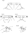
- the shows Fig. 1 a perspective view of an embodiment of the device according to the invention in the position of use, wherein the rod-shaped housing 1 is fixed by means of the retaining clip 2 on the nose of the user.
- the retaining clip 2 is designed in the form of two preferably resilient clamping legs 2a, 2b.
- an emitter 3 and / or detector is arranged in each case. In the exemplary embodiment shown, it is about a respective light source that emit visible light into the eyes of the user.
- the Fig. 2 shows a view of the embodiment of the device according to the invention according to Fig. 1 from the user's perspective and the Fig.
- each of the two emitters 3 is associated with an eye of the user and the main beam direction of the emitter 3 is to be aligned so that the best possible radiation of the Light takes place in the respective associated eye 19 of the user.
- the main beam directions are in the Fig. 3 indicated by arrows.
- the two clamping legs 2a, 2b of the retaining clip 2 are adjustable in their distance from each other, as shown in the Fig. 4 will be shown.
- the Fig. 4a and 4b show views, each with a different distance of the clamping legs 2a, 2b of the holding clamp 2 as seen by the user.
- the rod-shaped housing 1 can be made rotatable relative to the retaining clip 2 about the longitudinal axis of the rod-shaped housing 1 as shown in FIG Fig. 5 will be shown.
- the Fig. 5a and 5b show lateral views of this embodiment of the device according to the invention at different rotational position of the rod-shaped housing 1 relative to the retaining clip 2, wherein the straight arrows indicate the main beam direction of an emitter 3, and the curved peels the directions of rotation of the retaining clip 2 relative to the rod-shaped housing first
- the device according to the invention can also be attached to a pair of spectacles 5, as shown in FIG 6 and 7 will be shown.
- the retaining clip 2 may be designed accordingly, for example in the form of a retaining clip, as in the Fig. 6b is apparent. Since a minimum clamping force is required for the secure attachment to the glasses 5 in any case, a similar to a headband design as a holding clamp 2 is understood below.
- the Fig. 6a shows a view of such an embodiment as seen by the user and the Fig. 6b a side view.
- Fig. 7 is a perspective view of the attached to a pair of glasses 5 embodiment according to the Fig. 6 seen.
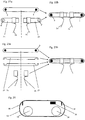
- a possible construction of a device according to the invention is explained.
- a power supply 6 is arranged, which is conductively connected to charging contacts 7, which are located respectively at the two ends of the rod-shaped housing 1.
- a control unit 8 for the emitter 3 and / or detector is provided within the rod-shaped housing 1, wherein in the embodiment shown, each of the two emitters 3 is driven with its own control unit 8.
- an emitter 3 is arranged in each case, in the embodiment shown in each case an LED light.
- a magnetic sensor 17 may be provided within the rod-shaped housing 1, the function of which will be explained below.
- the emitter 3 and / or detector may each be connected via a circuit board 22 to the power supply 6 and their respective associated control unit 8, which may be designed to be flexible as well.
- the flexible design also has about the advantage that the emission angle of the emitter 3 can be changed, as based on the Fig. 9 is explained.
- the Fig. 9a and 9b show detail views of two emission positions of a terminal arranged emitter 3 on a flexible board 22, wherein depending on the bending position of the board 22, the angle of the Main beam direction of the respective emitter 3 can be changed relative to a vertical plane.
- the main beam direction of the emitter 3 can also be changed by optical means.
- the Fig. 10 shows an example using a Fresnel lens 23, which is arranged in the two end regions of the rod-shaped housing 1 in the emission region of the relevant emitter 3.
- the 10a and 10b in this case show detailed views of two emission positions of an end arranged emitter 3, which is arranged relative to its associated Fresnel lens 23 slidably.
- the position of the emitter 3 can be factory set, or be made using external displacement mechanisms.
- FIG. 11 Another possibility for changing the main beam directions of the emitter 3 is in the Fig. 11 shown.
- the Fig. 11a-11c show detail views of different angles of radiation of three emitters 3, which are designed in the form of a light source group and are arranged at the ends, by driving different emitters 3 of the light source group.
- the different control of the light source group takes place via the control unit 8.
- the different main beam direction results from a different positioning of the selected emitter 3 of the light source group relative to a radiating opening 4 in the rod-shaped housing 1, which is arranged in the emission region of the emitter 3.
- the Fig. 12 shows one to Fig. 10 comparable embodiment, wherein different radiation angles of an end arranged emitter 3 are accomplished due to different rotational positions of a sleeve-shaped Fresnel lens 23, wherein the sleeve-shaped Fresnel lens 23 is rotatable about the longitudinal axis of the rod-shaped housing 1.
- the twistability is evident in the Fig. 12c can be seen, this embodiment according to the Fig. 12a and 12b seen in the longitudinal direction of the rod-shaped housing 1 shows.
- the curved arrows indicate the directions of rotation of the sleeve-shaped Fresnel lens 23, which is manufactured in its peripheral region with different optical properties.
- the main radiation direction of the emitted light is different be oriented as indicated by the curved arrows in the Fig. 12a and 12b is indicated.
- the emitters 3 arranged at the end are in each case designed to be pivotable relative to the rod-shaped housing 1, wherein the pivot axis is oriented perpendicular to the longitudinal axis of the rod-shaped housing 1.
- the main beam directions of the emitter 3 are indicated by rectilinear arrows and the pivoting direction by curved arrows.
- Fig. 14 is a view of a further embodiment of the device according to the invention shown with two emitter 3 each designed as a light source groups.
- an adjustment to different eye distances can be made by activating one of the light sources of each light source group or on the other hand reducing the intensity of each emitter 3 if all the emitters 3 of a light source group are activated. In the latter case, a dazzling effect on the user can be avoided.
- the device according to the invention is also suitable as a carrier for additional components whose arrangement near the eye can be advantageous and support the operation of the emitters 3 and / or detectors.
- the Fig. 15 shows, for example, an embodiment of the device according to the invention with additional cameras 9 and a brightness sensor 10.
- the cameras 9 can be used, for example, to detect eye movements or changes in the pupils of the user.
- the brightness sensor 10 detects the ambient light intensity and optionally reduces the intensity of the emitter 3 so as not to exceed a predetermined total light intensity on the eyes of the user.
- the external device 11 may be a mobile phone, for example act, which can be connected by means of a wireless connection to a user interface of the rod-shaped housing 1.
- the Fig. 17 shows a further application of the device according to the invention, in which the rod-shaped housing 1 is provided with two filter discs 12 attachable on both sides.
- These filter disks 12 may be, for example, color-tinted plastic films which have an orange color, for example, in order to filter out blue light coming from the outside. This achieves the opposite effect of the blue light, namely activation of the melatonin, whereby adverse effects of "jet lag" can be avoided.
- the Fig. 18 shows a possible course of the brightness of the light of the emitter 3 as a function of time, it being understood that after the device is put into operation, for example, a gradual increase in light brightness and a change in light color from incipient red to orange and yellow to the final blue light or blue - white light can take place to simulate a sunrise. Similarly, when the device is turned off, this process may be reversed to simulate a sunset. The simulation of a sunrise or sunset can be accomplished, for example, with several different colored emitters 3 (red, green and blue).
- the Fig. 19 represents a further embodiment of the device according to the invention with an optical Aufsteckhülse 20.
- the Aufsteckhülse 20 is pushed in the embodiment shown in the direction of the longitudinal axis of the rod-shaped housing 1 from the outside and covered in the deferred state, the radiation opening 4 of the respective emitter 3.
- the slip-on 20 changes while the emission of the emitter 3, by acting as a diffuser or the solid angle of the emitted light of the emitter 3 in question expands.
- FIG. 20 shown by the rod-shaped housing 1 is designed to be adjustable in length.
- the Figs. 20a and 20b show two different length positions of the rod-shaped housing 1, which can be realized approximately by a pull-out in the direction of the arrows shown.
- FIG. 21 A particularly slim and elegant design is in the Fig. 21 represented, in which the end arranged emitter 3 and / or detectors on thin side members 24 of the rod-shaped housing 1 are arranged.
- the rod-shaped housing 1 has a central region, on which the holding clamp 2 is fastened, as well as two end regions, which are designed in the form of the two side supports 24.
- This embodiment is particularly suitable for length adjustment of the entire arrangement by the side support 24 of the rod-shaped housing 1 relative to the central region and are pushed out.
- Fig. 22 a further embodiment of the device according to the invention is shown, in which the rod-shaped housing 1 can be provided with on both sides on its end portions in the longitudinal direction of the rod-shaped housing 1 attachable sleeves 21.
- the Fig. 22a shows the rod-shaped housing 1 and the sheaths 21 in the disassembled state
- the Fig. 22b the embodiment according to the Fig. 22a in the assembled state.
- the sheaths 21 each have an emission opening 4 ', which is aligned with the emission opening 4 of the rod-shaped housing 1 in the mounted state.
- the sheaths 21 furthermore each carry one of the clamping legs 2a, 2b, so that they form the retaining clip 2 in the mounted state.
- This embodiment has the advantage that the sheaths 21 can be replaced when worn or damaged and protect the rod-shaped housing 1.
- the Fig. 23a shows a further embodiment of the device according to the invention with attachable sleeves 21 in the disassembled state
- the Fig. 23b the embodiment according to the Fig. 23a in the assembled state.
- the sheath 21 is constructed in the form of two clamping body, which receive the rod-shaped housing 1 in the transverse direction between them.
- mounting sleeves for one clamping leg 2a, 2b can be pushed onto the mounted shell 21, which in turn form the retaining clip 2 in the mounted state.
- the Fig. 24-26 show an embodiment of a storage and loading container 13 for the device according to the invention.
- the storage and loading container 13 is provided with current sources 14 which are in a conductive connection with charging contacts 15.
- the current sources 14 may be designed as charging batteries.
- the current sources 14 can also be embodied as a rechargeable battery which can be recharged via its own charging electronics, for example via a micro USB connection.
- the charging contacts 7 of the rod-shaped housing 1 see Fig. 8
- the charging contacts 15 of the rod-shaped housing 1 in electrical contact with the charging contacts 15 as soon as the device according to the invention has been inserted into the storage and loading container 13.
- the storage and loading container 13 may be provided with a magnet 16, which comes to rest when the housing 1 is close to the magnetic sensor 17, which is arranged inside the rod-shaped housing 1.
- the control unit 8 located within the rod-shaped housing 1 can thus detect whether the device according to the invention has been inserted into the storage and loading container 13 and subsequently open a charging circuit for the power supply 6.
- the device according to the invention can also detect whether it has been removed from the storage and loading container 13 and start with a lighting cycle or terminate it as soon as it has been inserted into the storage and loading container 13.
- the Fig. 26 shows the storage and loading container 13 according to the Fig. 24 and 25 with inserted device according to the invention with the lid 18 of the storage and loading container 13.
- the storage and loading container 13 can be made very compact and can therefore be easily and inconspicuously carried by the user at any time.
- FIGS. 27 and 28 show a further embodiment of a storage and loading container 13 for the device according to the invention, wherein the Fig. 27 the storage and loading container 13 with inserted device according to the invention and the Fig. 28 the storage and loading container 13 according to the Fig. 27 in the open state without the device according to the invention represents.
- This embodiment of the storage and loading container 13 also has two charging contacts 15, wherein a charging contact 15 is arranged in an attachable charging sleeve 4, which is attachable to a central part of the storage and loading container 13.
- a further sleeve 25 can be plugged, which protects about a micro USB port.
- a current source 14 is provided, which is in conductive connection with the charging contacts 15.
- the charging contacts 7 of the rod-shaped housing 1 are in an electrical contact to the charging contacts 15.
- the storage and loading container 13 may be provided with a magnet 16 (in the FIGS. 27 and 28 not apparent), which comes to rest when the housing 1 is close to the magnetic sensor 17 which is arranged inside the rod-shaped housing 1.
- the control unit 8 located within the rod-shaped housing 1 can thus in turn detect whether the device according to the invention has been inserted into the storage and loading container 13 and subsequently open a charging circuit for the power supply 6.
- the portable device according to the invention can thus be made very compact, and also very practical storage and loading containers 13 are proposed.
- the invention provides a portable device for the optical signal transmission from and to the human eye ready, which can be worn inconspicuously close to the head with high wearing comfort and in particular enables a simultaneous wearing of the device with standard glasses. Furthermore, the handling, storage and transport of such devices are greatly facilitated.
Landscapes
- Health & Medical Sciences (AREA)
- Engineering & Computer Science (AREA)
- Biomedical Technology (AREA)
- Life Sciences & Earth Sciences (AREA)
- Public Health (AREA)
- Animal Behavior & Ethology (AREA)
- Veterinary Medicine (AREA)
- General Health & Medical Sciences (AREA)
- Nuclear Medicine, Radiotherapy & Molecular Imaging (AREA)
- Radiology & Medical Imaging (AREA)
- Pathology (AREA)
- Psychology (AREA)
- Psychiatry (AREA)
- Social Psychology (AREA)
- Hospice & Palliative Care (AREA)
- Developmental Disabilities (AREA)
- Child & Adolescent Psychology (AREA)
- Hematology (AREA)
- Anesthesiology (AREA)
- Heart & Thoracic Surgery (AREA)
- Acoustics & Sound (AREA)
- Physics & Mathematics (AREA)
- Biophysics (AREA)
- Eyeglasses (AREA)
- Arrangement Of Elements, Cooling, Sealing, Or The Like Of Lighting Devices (AREA)
- Eye Examination Apparatus (AREA)
- Optical Communication System (AREA)
Claims (8)
- Dispositif portatif pour la transmission optique de signaux en provenance et en direction de l'oeil humain avec au moins un émetteur (3) et/ou un détecteur d'ondes électromagnétiques, une alimentation électrique pour chaque au moins un émetteur (3) et/ou détecteur et une unité de commande (8) reliée à l'au moins un émetteur (3) et/ou détecteur, caractérisé en ce qu'il comporte un boîtier en forme de barre (1) dont les deux parties d'extrémité portent chacune au moins un émetteur (3) et/ou détecteur d'ondes électromagnétiques et qui présente dans sa partie médiane une pince de fixation (2), l'alimentation électrique de chaque au moins un émetteur (3) et/ou détecteur et l'unité de commande (8) qui est reliée à l'au moins un émetteur (3) et/ou détecteur étant disposées à l'intérieur du boîtier en forme de barre (1).
- Dispositif portatif selon la revendication 1, caractérisé en ce que le boîtier en forme de barre (1) est capable de rotation autour de son axe longitudinal par rapport à la pince de fixation (2).
- Dispositif portatif selon la revendication 1 ou 2, caractérisé en ce que chaque au moins un émetteur (3) et/ou détecteur est capable de rotation ou de pivotement par rapport au boîtier en forme de barre (1) autour d'un axe de rotation perpendiculaire à l'axe longitudinal du boîtier en forme de barre (1).
- Dispositif portatif selon l'une des revendications 1 à 3, caractérisé en ce que le boîtier en forme de barre (1) est ajustable en longueur.
- Dispositif portatif selon l'une des revendications 1 à 4, caractérisé en ce que l'au moins un émetteur (3) est une source lumineuse ou un groupe de sources lumineuses.
- Dispositif portatif selon la revendication 5, caractérisé en ce que les sources lumineuses d'un groupe de sources lumineuses peuvent être commandées séparément les unes des autres par l'unité de commande (8).
- Dispositif portatif selon l'une des revendications 1 à 6, caractérisé en ce que le boîtier en forme de barre (1) peut être relié par une liaison sans fil à un appareil externe (11).
- Dispositif portatif selon l'une des revendications 1 à 7, caractérisé en ce que le boîtier en forme de barre (1) est muni d'une douille emboîtable (20) qui contient les éléments optiques servant à former l'angle de rayonnement et/ou la luminosité de l'émetteur (3).
Applications Claiming Priority (2)
| Application Number | Priority Date | Filing Date | Title |
|---|---|---|---|
| ATA50694/2014A AT516326B1 (de) | 2014-09-29 | 2014-09-29 | Vorrichtung zur Signalübermittlung zum Auge |
| PCT/AT2015/050224 WO2016049669A1 (fr) | 2014-09-29 | 2015-09-09 | Dispositif pour la transmission d'un signal à l'œil |
Publications (2)
| Publication Number | Publication Date |
|---|---|
| EP3200875A1 EP3200875A1 (fr) | 2017-08-09 |
| EP3200875B1 true EP3200875B1 (fr) | 2018-06-27 |
Family
ID=54850298
Family Applications (1)
| Application Number | Title | Priority Date | Filing Date |
|---|---|---|---|
| EP15810728.4A Not-in-force EP3200875B1 (fr) | 2014-09-29 | 2015-09-09 | Dispositif pour la transmission d'un signal à l'oeil |
Country Status (8)
| Country | Link |
|---|---|
| US (1) | US9901748B2 (fr) |
| EP (1) | EP3200875B1 (fr) |
| CN (1) | CN107106863B (fr) |
| AT (1) | AT516326B1 (fr) |
| CA (1) | CA2961653C (fr) |
| DK (1) | DK3200875T3 (fr) |
| RU (1) | RU2716615C2 (fr) |
| WO (1) | WO2016049669A1 (fr) |
Cited By (1)
| Publication number | Priority date | Publication date | Assignee | Title |
|---|---|---|---|---|
| EP4513254A1 (fr) * | 2023-08-19 | 2025-02-26 | MOMES GmbH | Lumière émissive plaquette de nez |
Families Citing this family (12)
| Publication number | Priority date | Publication date | Assignee | Title |
|---|---|---|---|---|
| US10449326B2 (en) * | 2016-03-03 | 2019-10-22 | Headwaters R & D Inc | Audio tone programmed hygienic and therapeutic sleep and wake eye mask having remotely controlled sunrise and sunset multimodes |
| WO2018210636A1 (fr) * | 2017-05-15 | 2018-11-22 | Philips Lighting Holding B.V. | Système d'éclairage qui maintient des niveaux de lux mélanopique au niveau de l'œil indépendamment de la distance par rapport à l'utilisateur |
| WO2019028222A1 (fr) * | 2017-08-02 | 2019-02-07 | Multi Radiance Medical | Système et procédé pour diriger la lumière dans l'œil d'un patient |
| US11638833B2 (en) | 2017-08-02 | 2023-05-02 | Multi Radiance Medical | Reducing light polution in photobiomodulation therapy of a patients eye |
| EA202091244A1 (ru) * | 2017-11-17 | 2020-08-25 | Проджект Леа, Ллк | Устройство подсветки тела |
| WO2020064348A1 (fr) * | 2018-09-26 | 2020-04-02 | Osram Gmbh | Actionneur destiné à fournir une courbe d'éclairage |
| US11458328B2 (en) | 2018-10-22 | 2022-10-04 | Joovv, Inc. | Photobiomodulation therapy device accessories |
| US10478635B1 (en) | 2018-10-22 | 2019-11-19 | Joovv, Inc. | Photobiomodulation therapy systems and methods |
| DE102019108678A1 (de) * | 2019-04-03 | 2020-10-08 | Carl Zeiss Ag | Vorrichtung zur Energieversorgung eines aktiven Augenimplantats |
| USD963873S1 (en) | 2020-09-21 | 2022-09-13 | Joovv, Inc. | Floor stand for a photobiomodulation therapy device |
| USD1004789S1 (en) | 2020-09-21 | 2023-11-14 | Joovv, Inc. | Photobiomodulation therapy device |
| USD1047162S1 (en) | 2020-09-21 | 2024-10-15 | Joovv, Inc. | Photobiomodulation therapy device |
Family Cites Families (25)
| Publication number | Priority date | Publication date | Assignee | Title |
|---|---|---|---|---|
| FR2687322A1 (fr) | 1992-02-18 | 1993-08-20 | Darras Jean Claude | Appareil de traitement d'un sujet par illumination. |
| US5805267A (en) * | 1996-06-13 | 1998-09-08 | Goldman; Neil | Interactive light field for programmed non-visual stimulation and monitoring |
| DE10301867A1 (de) * | 2003-01-17 | 2004-07-29 | Günther, Andreas | Lichttherapievorrichtung |
| TW200602017A (en) * | 2004-07-08 | 2006-01-16 | Cwi Lighting Design Inc | LED phototherapeutic eyeglasses |
| DE102004048982A1 (de) * | 2004-10-01 | 2006-04-06 | Markus Klose | Augenvorsatz für ein Stimulationsgerät zum Stimulieren des Zentralnervensystems und der Gehirnströme eines Menschen |
| ATE479468T1 (de) * | 2007-04-18 | 2010-09-15 | Valkee Oy | Tragbare vorrichtung |
| JP2010527728A (ja) * | 2007-05-31 | 2010-08-19 | コーニンクレッカ フィリップス エレクトロニクス エヌ ヴィ | 光刺激及び生理的刺激をもたらす方法及びシステム |
| WO2009118066A1 (fr) | 2008-03-22 | 2009-10-01 | Turbolite Vertriebs Gmbh | Dispositif pour stabiliser et modifier les rythmes biologiques et pour traiter les arythmies |
| EP2384224B1 (fr) * | 2008-12-30 | 2015-09-09 | Koninklijke Philips N.V. | Système pour appliquer une photothérapie à un sujet |
| US20110125230A1 (en) * | 2009-11-23 | 2011-05-26 | Ronald Charles Friedman | Portable Light Therapy Devices |
| US8715328B2 (en) * | 2009-12-02 | 2014-05-06 | Ernesto Gerardo | Monocular light source positioning device and method for stimulating photoneuronic response |
| US9994228B2 (en) * | 2010-05-14 | 2018-06-12 | Iarmourholdings, Inc. | Systems and methods for controlling a vehicle or device in response to a measured human response to a provocative environment |
| EP2621587A4 (fr) * | 2010-09-29 | 2014-06-25 | Yumalite Inc | Dispositif de luminothérapie monté sur la tête |
| US9248309B2 (en) * | 2011-02-04 | 2016-02-02 | Johnson & Johnson Vision Care, Inc. | Light therapy system including spectacle frames and contact lenses |
| US20120203310A1 (en) * | 2011-02-04 | 2012-08-09 | Pugh Randall B | Spectacles for light therapy |
| EP2923638B1 (fr) * | 2011-03-18 | 2019-02-20 | SensoMotoric Instruments Gesellschaft für innovative Sensorik mbH | Dispositif et système de mesure optique |
| AU2012335699B2 (en) * | 2011-11-08 | 2017-06-15 | Biophotas, Inc. | Shapeable light therapy device and method |
| GB201203005D0 (en) | 2012-02-22 | 2012-04-04 | Polyphotonix Ltd | Medical apparatus and method |
| GB2506337B (en) * | 2012-07-29 | 2014-07-16 | Birju Patel | Head torch |
| US20160008568A1 (en) * | 2013-02-20 | 2016-01-14 | Sarah Beth Attia | Relaxation apparatus and method |
| US20150209597A1 (en) * | 2013-12-04 | 2015-07-30 | Michael E. Haarlander | Phototherapy eyeglass device |
| JP6270674B2 (ja) * | 2014-02-27 | 2018-01-31 | シチズン時計株式会社 | 投影装置 |
| US20160106950A1 (en) * | 2014-10-19 | 2016-04-21 | Curzio Vasapollo | Forehead-wearable light stimulator having one or more light pipes |
| US9889271B2 (en) * | 2015-01-05 | 2018-02-13 | Inteliclinic Inc. | System, apparatus and method for treating sleep disorder symptoms |
| NZ773822A (en) * | 2015-03-16 | 2022-07-29 | Magic Leap Inc | Methods and systems for diagnosing and treating health ailments |
-
2014
- 2014-09-29 AT ATA50694/2014A patent/AT516326B1/de not_active IP Right Cessation
-
2015
- 2015-09-09 EP EP15810728.4A patent/EP3200875B1/fr not_active Not-in-force
- 2015-09-09 DK DK15810728.4T patent/DK3200875T3/en active
- 2015-09-09 WO PCT/AT2015/050224 patent/WO2016049669A1/fr not_active Ceased
- 2015-09-09 RU RU2017108983A patent/RU2716615C2/ru active
- 2015-09-09 CA CA2961653A patent/CA2961653C/fr not_active Expired - Fee Related
- 2015-09-09 CN CN201580055006.1A patent/CN107106863B/zh not_active Expired - Fee Related
- 2015-09-09 US US15/512,124 patent/US9901748B2/en not_active Expired - Fee Related
Non-Patent Citations (1)
| Title |
|---|
| None * |
Cited By (1)
| Publication number | Priority date | Publication date | Assignee | Title |
|---|---|---|---|---|
| EP4513254A1 (fr) * | 2023-08-19 | 2025-02-26 | MOMES GmbH | Lumière émissive plaquette de nez |
Also Published As
| Publication number | Publication date |
|---|---|
| AT516326B1 (de) | 2016-07-15 |
| RU2017108983A (ru) | 2018-11-05 |
| RU2017108983A3 (fr) | 2019-03-21 |
| US20170274222A1 (en) | 2017-09-28 |
| DK3200875T3 (en) | 2018-10-01 |
| WO2016049669A1 (fr) | 2016-04-07 |
| CA2961653C (fr) | 2021-06-22 |
| RU2716615C2 (ru) | 2020-03-13 |
| CA2961653A1 (fr) | 2016-04-07 |
| CN107106863B (zh) | 2020-04-14 |
| CN107106863A (zh) | 2017-08-29 |
| AT516326A1 (de) | 2016-04-15 |
| US9901748B2 (en) | 2018-02-27 |
| EP3200875A1 (fr) | 2017-08-09 |
Similar Documents
| Publication | Publication Date | Title |
|---|---|---|
| EP3200875B1 (fr) | Dispositif pour la transmission d'un signal à l'oeil | |
| EP2804668B1 (fr) | Dispositif de neurostimulation | |
| EP4357842A2 (fr) | Appareil d'éclairage portable, dispositif de charge pour un appareil d'éclairage portable et système de commande pour un appareil d'éclairage portable | |
| US10857379B2 (en) | Diagnostic and treatment kit | |
| WO2004064922A1 (fr) | Dispositif de luminotherapie | |
| EP1642609B1 (fr) | Adaptateur pour les yeux à usage avec un dispositif de stimulation | |
| US20250076685A1 (en) | Portable light apparatus | |
| EP3874913B1 (fr) | Procédé pour faire fonctionner un corps d'éblouissement électronique et corps d'éblouissement électronique | |
| AT515197B1 (de) | Tragbare Vorrichtung zur Lichtemission | |
| EP2257338B1 (fr) | Dispositif pour stabiliser et modifier les rythmes biologiques et pour traiter les arythmies | |
| US20230330386A1 (en) | Light therapy glasses | |
| DE1622984A1 (de) | Fuer Augenuntersuchungen verwendbare Vorrichtung | |
| AT515923B1 (de) | Brillenbügel zur augengerichteten Lichtemission | |
| WO2020064348A1 (fr) | Actionneur destiné à fournir une courbe d'éclairage | |
| AT518153B1 (de) | Brille zur augengerichteten Lichtemission |
Legal Events
| Date | Code | Title | Description |
|---|---|---|---|
| PUAI | Public reference made under article 153(3) epc to a published international application that has entered the european phase |
Free format text: ORIGINAL CODE: 0009012 |
|
| 17P | Request for examination filed |
Effective date: 20170315 |
|
| AK | Designated contracting states |
Kind code of ref document: A1 Designated state(s): AL AT BE BG CH CY CZ DE DK EE ES FI FR GB GR HR HU IE IS IT LI LT LU LV MC MK MT NL NO PL PT RO RS SE SI SK SM TR |
|
| AX | Request for extension of the european patent |
Extension state: BA ME |
|
| DAV | Request for validation of the european patent (deleted) | ||
| DAX | Request for extension of the european patent (deleted) | ||
| GRAP | Despatch of communication of intention to grant a patent |
Free format text: ORIGINAL CODE: EPIDOSNIGR1 |
|
| INTG | Intention to grant announced |
Effective date: 20180206 |
|
| RIN1 | Information on inventor provided before grant (corrected) |
Inventor name: WALLERBERGER, MARK Inventor name: GEYER, MICHAEL |
|
| GRAS | Grant fee paid |
Free format text: ORIGINAL CODE: EPIDOSNIGR3 |
|
| GRAA | (expected) grant |
Free format text: ORIGINAL CODE: 0009210 |
|
| AK | Designated contracting states |
Kind code of ref document: B1 Designated state(s): AL AT BE BG CH CY CZ DE DK EE ES FI FR GB GR HR HU IE IS IT LI LT LU LV MC MK MT NL NO PL PT RO RS SE SI SK SM TR |
|
| REG | Reference to a national code |
Ref country code: GB Ref legal event code: FG4D Free format text: NOT ENGLISH |
|
| REG | Reference to a national code |
Ref country code: AT Ref legal event code: REF Ref document number: 1011759 Country of ref document: AT Kind code of ref document: T Effective date: 20180715 |
|
| REG | Reference to a national code |
Ref country code: IE Ref legal event code: FG4D Free format text: LANGUAGE OF EP DOCUMENT: GERMAN |
|
| REG | Reference to a national code |
Ref country code: DE Ref legal event code: R096 Ref document number: 502015004881 Country of ref document: DE |
|
| REG | Reference to a national code |
Ref country code: FR Ref legal event code: PLFP Year of fee payment: 4 |
|
| REG | Reference to a national code |
Ref country code: NL Ref legal event code: FP |
|
| REG | Reference to a national code |
Ref country code: CH Ref legal event code: NV Representative=s name: PATENTANWAELTE SCHAAD, BALASS, MENZL AND PARTN, CH |
|
| REG | Reference to a national code |
Ref country code: DK Ref legal event code: T3 Effective date: 20180924 |
|
| REG | Reference to a national code |
Ref country code: SE Ref legal event code: TRGR |
|
| REG | Reference to a national code |
Ref country code: NO Ref legal event code: T2 Effective date: 20180627 |
|
| PG25 | Lapsed in a contracting state [announced via postgrant information from national office to epo] |
Ref country code: BG Free format text: LAPSE BECAUSE OF FAILURE TO SUBMIT A TRANSLATION OF THE DESCRIPTION OR TO PAY THE FEE WITHIN THE PRESCRIBED TIME-LIMIT Effective date: 20180927 Ref country code: LT Free format text: LAPSE BECAUSE OF FAILURE TO SUBMIT A TRANSLATION OF THE DESCRIPTION OR TO PAY THE FEE WITHIN THE PRESCRIBED TIME-LIMIT Effective date: 20180627 |
|
| REG | Reference to a national code |
Ref country code: LT Ref legal event code: MG4D |
|
| PG25 | Lapsed in a contracting state [announced via postgrant information from national office to epo] |
Ref country code: GR Free format text: LAPSE BECAUSE OF FAILURE TO SUBMIT A TRANSLATION OF THE DESCRIPTION OR TO PAY THE FEE WITHIN THE PRESCRIBED TIME-LIMIT Effective date: 20180928 Ref country code: HR Free format text: LAPSE BECAUSE OF FAILURE TO SUBMIT A TRANSLATION OF THE DESCRIPTION OR TO PAY THE FEE WITHIN THE PRESCRIBED TIME-LIMIT Effective date: 20180627 Ref country code: LV Free format text: LAPSE BECAUSE OF FAILURE TO SUBMIT A TRANSLATION OF THE DESCRIPTION OR TO PAY THE FEE WITHIN THE PRESCRIBED TIME-LIMIT Effective date: 20180627 Ref country code: RS Free format text: LAPSE BECAUSE OF FAILURE TO SUBMIT A TRANSLATION OF THE DESCRIPTION OR TO PAY THE FEE WITHIN THE PRESCRIBED TIME-LIMIT Effective date: 20180627 |
|
| PG25 | Lapsed in a contracting state [announced via postgrant information from national office to epo] |
Ref country code: RO Free format text: LAPSE BECAUSE OF FAILURE TO SUBMIT A TRANSLATION OF THE DESCRIPTION OR TO PAY THE FEE WITHIN THE PRESCRIBED TIME-LIMIT Effective date: 20180627 Ref country code: CZ Free format text: LAPSE BECAUSE OF FAILURE TO SUBMIT A TRANSLATION OF THE DESCRIPTION OR TO PAY THE FEE WITHIN THE PRESCRIBED TIME-LIMIT Effective date: 20180627 Ref country code: PL Free format text: LAPSE BECAUSE OF FAILURE TO SUBMIT A TRANSLATION OF THE DESCRIPTION OR TO PAY THE FEE WITHIN THE PRESCRIBED TIME-LIMIT Effective date: 20180627 Ref country code: EE Free format text: LAPSE BECAUSE OF FAILURE TO SUBMIT A TRANSLATION OF THE DESCRIPTION OR TO PAY THE FEE WITHIN THE PRESCRIBED TIME-LIMIT Effective date: 20180627 Ref country code: IS Free format text: LAPSE BECAUSE OF FAILURE TO SUBMIT A TRANSLATION OF THE DESCRIPTION OR TO PAY THE FEE WITHIN THE PRESCRIBED TIME-LIMIT Effective date: 20181027 Ref country code: SK Free format text: LAPSE BECAUSE OF FAILURE TO SUBMIT A TRANSLATION OF THE DESCRIPTION OR TO PAY THE FEE WITHIN THE PRESCRIBED TIME-LIMIT Effective date: 20180627 |
|
| PG25 | Lapsed in a contracting state [announced via postgrant information from national office to epo] |
Ref country code: ES Free format text: LAPSE BECAUSE OF FAILURE TO SUBMIT A TRANSLATION OF THE DESCRIPTION OR TO PAY THE FEE WITHIN THE PRESCRIBED TIME-LIMIT Effective date: 20180627 Ref country code: IT Free format text: LAPSE BECAUSE OF FAILURE TO SUBMIT A TRANSLATION OF THE DESCRIPTION OR TO PAY THE FEE WITHIN THE PRESCRIBED TIME-LIMIT Effective date: 20180627 Ref country code: SM Free format text: LAPSE BECAUSE OF FAILURE TO SUBMIT A TRANSLATION OF THE DESCRIPTION OR TO PAY THE FEE WITHIN THE PRESCRIBED TIME-LIMIT Effective date: 20180627 |
|
| REG | Reference to a national code |
Ref country code: DE Ref legal event code: R097 Ref document number: 502015004881 Country of ref document: DE |
|
| PG25 | Lapsed in a contracting state [announced via postgrant information from national office to epo] |
Ref country code: MC Free format text: LAPSE BECAUSE OF FAILURE TO SUBMIT A TRANSLATION OF THE DESCRIPTION OR TO PAY THE FEE WITHIN THE PRESCRIBED TIME-LIMIT Effective date: 20180627 |
|
| PLBE | No opposition filed within time limit |
Free format text: ORIGINAL CODE: 0009261 |
|
| STAA | Information on the status of an ep patent application or granted ep patent |
Free format text: STATUS: NO OPPOSITION FILED WITHIN TIME LIMIT |
|
| 26N | No opposition filed |
Effective date: 20190328 |
|
| REG | Reference to a national code |
Ref country code: BE Ref legal event code: MM Effective date: 20180930 |
|
| REG | Reference to a national code |
Ref country code: IE Ref legal event code: MM4A |
|
| PG25 | Lapsed in a contracting state [announced via postgrant information from national office to epo] |
Ref country code: LU Free format text: LAPSE BECAUSE OF NON-PAYMENT OF DUE FEES Effective date: 20180909 |
|
| PG25 | Lapsed in a contracting state [announced via postgrant information from national office to epo] |
Ref country code: IE Free format text: LAPSE BECAUSE OF NON-PAYMENT OF DUE FEES Effective date: 20180909 |
|
| PG25 | Lapsed in a contracting state [announced via postgrant information from national office to epo] |
Ref country code: BE Free format text: LAPSE BECAUSE OF NON-PAYMENT OF DUE FEES Effective date: 20180930 Ref country code: SI Free format text: LAPSE BECAUSE OF FAILURE TO SUBMIT A TRANSLATION OF THE DESCRIPTION OR TO PAY THE FEE WITHIN THE PRESCRIBED TIME-LIMIT Effective date: 20180627 |
|
| PG25 | Lapsed in a contracting state [announced via postgrant information from national office to epo] |
Ref country code: AL Free format text: LAPSE BECAUSE OF FAILURE TO SUBMIT A TRANSLATION OF THE DESCRIPTION OR TO PAY THE FEE WITHIN THE PRESCRIBED TIME-LIMIT Effective date: 20180627 |
|
| PG25 | Lapsed in a contracting state [announced via postgrant information from national office to epo] |
Ref country code: MT Free format text: LAPSE BECAUSE OF FAILURE TO SUBMIT A TRANSLATION OF THE DESCRIPTION OR TO PAY THE FEE WITHIN THE PRESCRIBED TIME-LIMIT Effective date: 20180627 |
|
| PGFP | Annual fee paid to national office [announced via postgrant information from national office to epo] |
Ref country code: CH Payment date: 20190903 Year of fee payment: 5 |
|
| PG25 | Lapsed in a contracting state [announced via postgrant information from national office to epo] |
Ref country code: TR Free format text: LAPSE BECAUSE OF FAILURE TO SUBMIT A TRANSLATION OF THE DESCRIPTION OR TO PAY THE FEE WITHIN THE PRESCRIBED TIME-LIMIT Effective date: 20180627 |
|
| PG25 | Lapsed in a contracting state [announced via postgrant information from national office to epo] |
Ref country code: PT Free format text: LAPSE BECAUSE OF FAILURE TO SUBMIT A TRANSLATION OF THE DESCRIPTION OR TO PAY THE FEE WITHIN THE PRESCRIBED TIME-LIMIT Effective date: 20180627 |
|
| PG25 | Lapsed in a contracting state [announced via postgrant information from national office to epo] |
Ref country code: HU Free format text: LAPSE BECAUSE OF FAILURE TO SUBMIT A TRANSLATION OF THE DESCRIPTION OR TO PAY THE FEE WITHIN THE PRESCRIBED TIME-LIMIT; INVALID AB INITIO Effective date: 20150909 Ref country code: CY Free format text: LAPSE BECAUSE OF FAILURE TO SUBMIT A TRANSLATION OF THE DESCRIPTION OR TO PAY THE FEE WITHIN THE PRESCRIBED TIME-LIMIT Effective date: 20180627 Ref country code: MK Free format text: LAPSE BECAUSE OF NON-PAYMENT OF DUE FEES Effective date: 20180627 |
|
| PGFP | Annual fee paid to national office [announced via postgrant information from national office to epo] |
Ref country code: FR Payment date: 20200910 Year of fee payment: 6 Ref country code: GB Payment date: 20200925 Year of fee payment: 6 Ref country code: DK Payment date: 20200922 Year of fee payment: 6 Ref country code: FI Payment date: 20200918 Year of fee payment: 6 Ref country code: NL Payment date: 20200918 Year of fee payment: 6 Ref country code: NO Payment date: 20200922 Year of fee payment: 6 |
|
| PGFP | Annual fee paid to national office [announced via postgrant information from national office to epo] |
Ref country code: SE Payment date: 20200925 Year of fee payment: 6 |
|
| REG | Reference to a national code |
Ref country code: CH Ref legal event code: PL |
|
| PG25 | Lapsed in a contracting state [announced via postgrant information from national office to epo] |
Ref country code: LI Free format text: LAPSE BECAUSE OF NON-PAYMENT OF DUE FEES Effective date: 20200930 Ref country code: CH Free format text: LAPSE BECAUSE OF NON-PAYMENT OF DUE FEES Effective date: 20200930 |
|
| REG | Reference to a national code |
Ref country code: AT Ref legal event code: MM01 Ref document number: 1011759 Country of ref document: AT Kind code of ref document: T Effective date: 20200909 |
|
| PGFP | Annual fee paid to national office [announced via postgrant information from national office to epo] |
Ref country code: DE Payment date: 20210928 Year of fee payment: 7 |
|
| PG25 | Lapsed in a contracting state [announced via postgrant information from national office to epo] |
Ref country code: AT Free format text: LAPSE BECAUSE OF NON-PAYMENT OF DUE FEES Effective date: 20200909 |
|
| REG | Reference to a national code |
Ref country code: FI Ref legal event code: MAE |
|
| REG | Reference to a national code |
Ref country code: NO Ref legal event code: MMEP |
|
| PG25 | Lapsed in a contracting state [announced via postgrant information from national office to epo] |
Ref country code: FI Free format text: LAPSE BECAUSE OF NON-PAYMENT OF DUE FEES Effective date: 20210909 |
|
| REG | Reference to a national code |
Ref country code: DK Ref legal event code: EBP Effective date: 20210930 |
|
| REG | Reference to a national code |
Ref country code: SE Ref legal event code: EUG |
|
| REG | Reference to a national code |
Ref country code: NL Ref legal event code: MM Effective date: 20211001 |
|
| GBPC | Gb: european patent ceased through non-payment of renewal fee |
Effective date: 20210909 |
|
| PG25 | Lapsed in a contracting state [announced via postgrant information from national office to epo] |
Ref country code: NL Free format text: LAPSE BECAUSE OF NON-PAYMENT OF DUE FEES Effective date: 20211001 |
|
| PG25 | Lapsed in a contracting state [announced via postgrant information from national office to epo] |
Ref country code: SE Free format text: LAPSE BECAUSE OF NON-PAYMENT OF DUE FEES Effective date: 20210910 Ref country code: NO Free format text: LAPSE BECAUSE OF NON-PAYMENT OF DUE FEES Effective date: 20210930 Ref country code: GB Free format text: LAPSE BECAUSE OF NON-PAYMENT OF DUE FEES Effective date: 20210909 Ref country code: FR Free format text: LAPSE BECAUSE OF NON-PAYMENT OF DUE FEES Effective date: 20210930 |
|
| PG25 | Lapsed in a contracting state [announced via postgrant information from national office to epo] |
Ref country code: DK Free format text: LAPSE BECAUSE OF NON-PAYMENT OF DUE FEES Effective date: 20210930 |
|
| REG | Reference to a national code |
Ref country code: DE Ref legal event code: R119 Ref document number: 502015004881 Country of ref document: DE |
|
| PG25 | Lapsed in a contracting state [announced via postgrant information from national office to epo] |
Ref country code: DE Free format text: LAPSE BECAUSE OF NON-PAYMENT OF DUE FEES Effective date: 20230401 |