EP3201027B1 - Brechbare anordnung einer länglichen dünnen lippe in einer relativ schmalen länglichen nut und anwendung davon zur montage einer luftführung auf einer düse - Google Patents
Brechbare anordnung einer länglichen dünnen lippe in einer relativ schmalen länglichen nut und anwendung davon zur montage einer luftführung auf einer düse Download PDFInfo
- Publication number
- EP3201027B1 EP3201027B1 EP15788129.3A EP15788129A EP3201027B1 EP 3201027 B1 EP3201027 B1 EP 3201027B1 EP 15788129 A EP15788129 A EP 15788129A EP 3201027 B1 EP3201027 B1 EP 3201027B1
- Authority
- EP
- European Patent Office
- Prior art keywords
- elongate
- assembly
- thin lip
- lip
- notch
- Prior art date
- Legal status (The legal status is an assumption and is not a legal conclusion. Google has not performed a legal analysis and makes no representation as to the accuracy of the status listed.)
- Active
Links
Images

Classifications
-
- B—PERFORMING OPERATIONS; TRANSPORTING
- B60—VEHICLES IN GENERAL
- B60K—ARRANGEMENT OR MOUNTING OF PROPULSION UNITS OR OF TRANSMISSIONS IN VEHICLES; ARRANGEMENT OR MOUNTING OF PLURAL DIVERSE PRIME-MOVERS IN VEHICLES; AUXILIARY DRIVES FOR VEHICLES; INSTRUMENTATION OR DASHBOARDS FOR VEHICLES; ARRANGEMENTS IN CONNECTION WITH COOLING, AIR INTAKE, GAS EXHAUST OR FUEL SUPPLY OF PROPULSION UNITS IN VEHICLES
- B60K11/00—Arrangement in connection with cooling of propulsion units
- B60K11/02—Arrangement in connection with cooling of propulsion units with liquid cooling
- B60K11/04—Arrangement or mounting of radiators, radiator shutters, or radiator blinds
-
- B—PERFORMING OPERATIONS; TRANSPORTING
- B60—VEHICLES IN GENERAL
- B60K—ARRANGEMENT OR MOUNTING OF PROPULSION UNITS OR OF TRANSMISSIONS IN VEHICLES; ARRANGEMENT OR MOUNTING OF PLURAL DIVERSE PRIME-MOVERS IN VEHICLES; AUXILIARY DRIVES FOR VEHICLES; INSTRUMENTATION OR DASHBOARDS FOR VEHICLES; ARRANGEMENTS IN CONNECTION WITH COOLING, AIR INTAKE, GAS EXHAUST OR FUEL SUPPLY OF PROPULSION UNITS IN VEHICLES
- B60K11/00—Arrangement in connection with cooling of propulsion units
- B60K11/08—Air inlets for cooling; Shutters or blinds therefor
-
- B—PERFORMING OPERATIONS; TRANSPORTING
- B60—VEHICLES IN GENERAL
- B60Y—INDEXING SCHEME RELATING TO ASPECTS CROSS-CUTTING VEHICLE TECHNOLOGY
- B60Y2306/00—Other features of vehicle sub-units
- B60Y2306/01—Reducing damages in case of crash, e.g. by improving battery protection
Definitions
- the present invention relates to a fusible assembly of a relatively thin elongate lip in a relatively narrow elongate slot, and its application to the assembly of an air guide on a nozzle.
- the first element having at least one wall terminating in a relatively thin elongate lip or blade which must be closely received in an elongate slot formed in the second element.
- the upper and lower walls of an air guide comprises at the top and bottom horizontal parallel walls on which parallel plates attached by a long side to the wall form thin elongated slots open on three sides;
- the air guide comprises in the upper and lower part two elongate lips with straight edges which must be introduced into the narrow parallel slots of the nozzle; as a result of this interlocking, the air guide is finally fixed on the nozzle by means of appropriate complementary clipping elements.
- a shock it happens that the lip remains locked in the slot, degrading the absorption of shock in this area. This can be penalizing in the context of "RCAR" shocks used for the classification of a vehicle by insurance.
- the document JP 2007 326431 A discloses an assembly of a first member with a second member, formed by assembling an elongated thin lip belonging to the second member in a narrow slot of the first member.
- the object of the invention is to provide an assembly of a relatively thin elongated lip in a relatively narrow three-sided elongated slot, which has an improved shock absorption capability.
- the invention achieves its goal by assembling a first member with a second member, formed by assembling an elongated thin lip belonging to the second member in a narrow slot an elongated plate formed by the three sides of an elongate flat plate fixed parallel to a flat wall of the first element, characterized in that the elongated thin lip has, in the direction of the first element, a free edge having at least one primer notch of rupture and in that the elongated slot comprises, opposite said at least one notch, a rib arranged to come into contact with the bottom of said notch during an advance of the elongated thin lip towards said first element beyond a predetermined assembly position to cause tearing of said elongate thin lip.
- the predetermined assembly position may be a normal nesting position of the lip in the slot, ie before any shock.
- the assembly is the assembly of an air guide on a fan nozzle in a motor vehicle.
- front, rear, upper, lower refer to the front and rear directions of the vehicle, when the intake system is mounted on the vehicle.
- the X axes, Y, Z respectively correspond to the longitudinal (front to back), transverse and vertical axis of the vehicle.
- substantially horizontal, longitudinal or vertical means a direction / plane forming an angle of not more than ⁇ 20 °, or not more than 10 ° or not more than 5 °, with a direction / a horizontal, longitudinal plane or vertical.
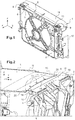
- the assembly according to the invention aims to fit an air guide 1 (second element) on the nozzle 2 (first element) of a motor-fan unit.
- the nozzle 2 is in the form of a rectangular rigid frame extending vertically and transversely to the longitudinal front-rear direction of the vehicle.
- This frame has in particular two horizontal walls respectively high and low, of which only the upper horizontal wall 4 is visible in the figures.
- an elongated parallel rectangular plate 6 attaches to the wall 4 by a foot 5 along the long side of the plate 6; the other three sides of the plate 6 (another large side 8 and two small sides 9) form the open edges (or free edges) of a horizontal slit 10 open towards the front (i.e. air guide 1) and laterally.
- the term "side” is understood here as a peripheral edge of the plate 6.
- the air guide 1 is in the form of a rectangular frame comprising essentially two high and low horizontal walls, of which only the high horizontal wall 11 is visible in the figures, connected by vertical sides 12.
- the horizontal walls 11 end towards the rear by a rear lip 13, directed towards the nozzle 2, and which must fit relatively tightly in the respective slots of said nozzle 2.
- the lip 13 and the slot 10 located in the upper part of the assembly are shown, but the invention also applies to the lip and the slot located in the lower part.
- the lip 13 has on one free edge 14 in the direction of the nozzle 2 one or more incipient fracture notches 15 and the elongated slot 10 has, next to each notch 15, a rib 16 arranged in such a manner that to come into contact with the bottom of the corresponding notch 15 during an advance of the lip 13 towards the nozzle 2 beyond a predetermined assembly position, corresponding to the position of the figure 4 .
- the plate 6 has been removed to make visible the notches 15 and the ribs 16.
- the assembly comprises five notches 15 each associated with a rib 16. These notches 15 have a V-shape.
- the invention is however not limited to a particular number of notches / ribs, nor to a particular form of notch 15. In particular, the shape of the notches could be rounded.
- Each notch 15 may also be made in an area 17 of the lip 13 having a thickness less than that of the remainder of the lip 13, as shown in FIG. figure 3 .
- the thickness may for example be reduced by 50 to 80% in these areas 17.
- the lip 13 may have a tapered shape towards its free edge 14. In other words, the thickness of the lip 13 decreases continuously from the air guide 1 to the free edge 14.
- the ribs 16 may extend substantially perpendicular to the free edge 14 of the lip 13, namely substantially in the direction of engagement of the air guide 1 in the nozzle 2 (here in the longitudinal direction X). These ribs 16 extend substantially perpendicular to the wall 4 of the nozzle 2. Here, they are integral with the foot of attachment 5. These ribs 16 may also have a tapered shape towards the lip 13, ie a decreasing thickness of continuously, in order to promote the tearing of the lip 13.
- each rib 16 is at least partially engaged within the corresponding notch 15.
- each rib 16 will thus come into contact with the bottom of the notch 15 associated and it is understood that the beginning of the tearing of the lip 13 can be controlled by appropriately selecting the distance between the rib 16 and the bottom of the associated notch 15 in the normal interlocking position. in other words, before any shock.
- the assembly according to the invention can be arranged to facilitate the assembly of the lip 13 inside the slot 10 during assembly of the air guide 1 on the nozzle 2.
- the front corners 18 of the plate 6 may be "horny", that is to say, raised upwardly along a "fold” 19 arranged diagonally ( figure 2 ).
- the horizontal slit 10 has a substantially constant thickness throughout its entire extent, except in the areas formed by these corners 18 where the thickness of the slot increases in the direction of the angle.
- the lip 13 is further curvilinear and concave rearwards, so that it forms, in the direction of the nozzle 2, an edge 14 in an elliptical arc ending laterally with two forward lateral points 20.
- the assembler When presenting one in front of the other the air guide 1 and the nozzle 2 ( figure 2 ), the assembler places the tips 20 of the curvilinear edge 14 opposite the zones of increased thickness formed by the raised corners 18, which is quite easy, so that by continuing the approach movement of an element towards the other, these tips 20 can come against the lower surface of said raised corners 18 and be progressively guided by said surface to the nominal thickness areas of the slot 10.
- the curvilinear shape of the edge 14 allows the rest of the lip 13 to advance without difficulty, gradually, to get into the slot 10.
- one or more guide elements integral with the long side 8 of the plate 6 and extending in the extension of the plate 6 away of the wall 4 of the nozzle 2 away from it.
- the ribs 16 may form wedging ribs for better retention of the lip 13 of the air guide 1 inside the slot 10.
- These ribs 16 may in particular be arranged to cooperate with the lip 13 during its introduction into the slot 10 so as to guide it to the bottom of the latter and to wedge perpendicularly to the flat wall 4 when fully inserted into the slot 10.
- they may have a height more and more elevation of the edge of the slot towards the bottom of the slot, guiding the lip 13 inside the slot 10. It will be noted that only the portion of the rib 16 extending over the entire height separating the plate 6 from the wall 4 can then penetrate into the notch 15 and cause the tearing of the lip 13.
Landscapes
- Engineering & Computer Science (AREA)
- Chemical & Material Sciences (AREA)
- Combustion & Propulsion (AREA)
- Transportation (AREA)
- Mechanical Engineering (AREA)
- Structures Of Non-Positive Displacement Pumps (AREA)
Claims (10)
- Zusammenbau eines ersten Elements (2) mit einem zweiten Element (1), hergestellt durch das Einfügen einer zum zweiten Element (1) gehörenden länglichen dünnen Lippe (13) in einen länglichen schmalen Schlitz (10), der von den drei Seiten einer länglichen ebenen Platte (6) geformt wird, die parallel an einer ebenen Wand (4) des ersten Elements (2) befestigt ist, dadurch gekennzeichnet, dass die längliche dünne Lippe (13) in Richtung des ersten Elements (2) einen freien Rand (14) hat, der mindestens eine Sollbruchstellenkerbe (15) aufweist, und dass der längliche Schlitz (10) gegenüber der mindestens einen Kerbe (15) eine Rippe (16) aufweist, die so eingerichtet ist, dass sie bei einem Vorschub der länglichen dünnen Lippe (13) zum ersten Element (1) über eine vorbestimmte Zusammenbaustellung hinaus mit dem Boden der Kerbe (15) in Kontakt kommt, um ein Reißen der länglichen dünnen Lippe hervorzurufen.
- Zusammenbau nach Anspruch 1, dadurch gekennzeichnet, dass jede Rippe (16) zumindest zum Teil in eine entsprechende Kerbe (15) eingeführt wird, wenn die längliche dünne Lippe (13) in der vorbestimmten Zusammenbaustellung ins Innere des Schlitzes (10) eingefügt wird.
- Zusammenbau nach einem der Ansprüche 1 oder 2, dadurch gekennzeichnet, dass die Rippe (16) sich zwischen der länglichen ebenen Platte (6) und der ebenen Wand (4) im Wesentlichen lotrecht zum freien Rand (14) der länglichen dünnen Lippe (13) erstreckt.
- Zusammenbau nach einem der Ansprüche 1 bis 3, dadurch gekennzeichnet, dass jede Kerbe (15) in einem Bereich (17) der länglichen dünnen Lippe (13) hergestellt wird, der eine geringere Dicke als der Rest der länglichen dünnen Lippe (13) aufweist.
- Zusammenbau nach Anspruch 4, dadurch gekennzeichnet, dass der Bereich (17) eine Dicke von 50 bis 80% der Dicke der länglichen dünnen Lippe (13) aufweist.
- Zusammenbau nach einem der Ansprüche 1 bis 5, dadurch gekennzeichnet, dass die Dicke der länglichen dünnen Lippe (13) ausgehend vom zweiten Element (1) zum freien Rand (14) der länglichen dünnen Lippe (13) kontinuierlich abnimmt.
- Zusammenbau nach einem der Ansprüche 1 bis 6, dadurch gekennzeichnet, dass die Dicke einer Rippe (16) in Richtung der gegenüber befindlichen Kerbe (15) kontinuierlich kontinuierlich abnimmt.
- Zusammenbau nach einem der Ansprüche 1 bis 7, dadurch gekennzeichnet, dass er eine Vielzahl von Kerben (15) und Rippen (16) aufweist, die einander gegenüber angeordnet sind.
- Zusammenbau nach einem der Ansprüche 1 bis 8, dadurch gekennzeichnet, dass die Kerbe (15) im Wesentlichen eine V-Form aufweist.
- Zusammenbau nach einem der Ansprüche 1 bis 9, dadurch gekennzeichnet, dass es sich um den Einbau eines Luftleiters (1) auf eine Lüfterdüse (2) in einem Kraftfahrzeug handelt.
Applications Claiming Priority (2)
| Application Number | Priority Date | Filing Date | Title |
|---|---|---|---|
| FR1459486A FR3026797B1 (fr) | 2014-10-03 | 2014-10-03 | Assemblage fusible d'une levre mince allongee dans une fente allongee relativement etroite, et son application a l'assemblage d'un guide-air sur une buse |
| PCT/FR2015/052638 WO2016051101A1 (fr) | 2014-10-03 | 2015-10-02 | Assemblage fusible d'une levre mince allongee dans une fente allongee relativement etroite et son application a l'assemblage d'un guide-air sur une buse |
Publications (2)
| Publication Number | Publication Date |
|---|---|
| EP3201027A1 EP3201027A1 (de) | 2017-08-09 |
| EP3201027B1 true EP3201027B1 (de) | 2019-12-04 |
Family
ID=51987368
Family Applications (1)
| Application Number | Title | Priority Date | Filing Date |
|---|---|---|---|
| EP15788129.3A Active EP3201027B1 (de) | 2014-10-03 | 2015-10-02 | Brechbare anordnung einer länglichen dünnen lippe in einer relativ schmalen länglichen nut und anwendung davon zur montage einer luftführung auf einer düse |
Country Status (3)
| Country | Link |
|---|---|
| EP (1) | EP3201027B1 (de) |
| FR (1) | FR3026797B1 (de) |
| WO (1) | WO2016051101A1 (de) |
Families Citing this family (1)
| Publication number | Priority date | Publication date | Assignee | Title |
|---|---|---|---|---|
| FR3091498B1 (fr) * | 2019-01-04 | 2020-12-18 | Renault Sas | Guide d’air d’une face avant d’un vehicule automobile |
Family Cites Families (5)
| Publication number | Priority date | Publication date | Assignee | Title |
|---|---|---|---|---|
| DE19849760A1 (de) * | 1998-10-28 | 2000-05-11 | Norsk Hydro As | Vorrichtung zum Absorbieren von Bewegungsenergie im Falle eines Aufpralls |
| JP2004284438A (ja) * | 2003-03-20 | 2004-10-14 | Toyota Motor Corp | 車体前部の導風構造 |
| JP2007326431A (ja) * | 2006-06-07 | 2007-12-20 | Denso Corp | シールダクト |
| FR2969729B1 (fr) * | 2010-12-24 | 2013-02-08 | Eads Europ Aeronautic Defence | Piece structurale a capacite de dissipation d'energie |
| FR3002602B1 (fr) * | 2013-02-26 | 2015-02-27 | Renault Sa | Assemblage d'une levre mince allongee dans une fente etroite allongee et application a l'assemblage d'un guide-air sur une buse |
-
2014
- 2014-10-03 FR FR1459486A patent/FR3026797B1/fr not_active Expired - Fee Related
-
2015
- 2015-10-02 EP EP15788129.3A patent/EP3201027B1/de active Active
- 2015-10-02 WO PCT/FR2015/052638 patent/WO2016051101A1/fr not_active Ceased
Non-Patent Citations (1)
| Title |
|---|
| None * |
Also Published As
| Publication number | Publication date |
|---|---|
| FR3026797B1 (fr) | 2017-05-12 |
| FR3026797A1 (fr) | 2016-04-08 |
| WO2016051101A1 (fr) | 2016-04-07 |
| EP3201027A1 (de) | 2017-08-09 |
Similar Documents
| Publication | Publication Date | Title |
|---|---|---|
| EP3144199B1 (de) | Vorrichtung zur erhöhung von komfort, insbesondere für ein schienenfahrzeug, umfassend einen herausnehmbaren tisch | |
| EP3824197B1 (de) | Befestigungsvorrichtung für zwei flache elemente | |
| EP0878343A1 (de) | Sitzschiene für Kraftfahrzeugsitze | |
| FR2945064A1 (fr) | Dispositif a lames brise-vue equipe de moyens de retenue des lames et lame correspondante | |
| EP3592631B1 (de) | Anordnung zum halten eines gepäckraumbehälters an der vorderseite einer kraftfahrzeugkarosseriestruktur | |
| EP2445748B1 (de) | Befestigungsvorrichtung eines sitzteiles am fussboden eines fahrzeuges | |
| EP3996954B1 (de) | Vorrichtung zur befestigung eines seitlichen randprofilteils einer kraftfahrzeugtür | |
| EP2961998B1 (de) | Anordnung eines länglichen dünnen lippe in einem länglichen enger schlitz und verwendung zur montage einer luftführung auf einer zarge | |
| WO2016051101A1 (fr) | Assemblage fusible d'une levre mince allongee dans une fente allongee relativement etroite et son application a l'assemblage d'un guide-air sur une buse | |
| EP3677463B1 (de) | Luftführung einer frontseite eines kraftfahrzeugs | |
| EP3126209B1 (de) | Verstärkte kraftfahrzeug struktur | |
| WO2017153649A1 (fr) | Embase de retroviseur extérieur de véhicule automobile avec crochet de fixation provisoire | |
| EP1094695B1 (de) | Pfosten für ein Metallgerippe, insbesondere für ein Rahmengestell eines Schaltschrankes | |
| EP3927602B1 (de) | Verkleidungseinrichtung eines fahrzeuges | |
| EP4371819A1 (de) | Ausrüstung eines kraftfahrzeugs | |
| EP2189599B1 (de) | Stulpschiene für ein Schloss, Schloss mit Stulpschiene und Schiebetür mir einem solchen Schloss | |
| EP3074641B1 (de) | Verbindung einer führung mit einer länglichen lippe in einem länglichen schlitz und anwendung auf eine verbindung einer luftführung mit einer düse | |
| EP3360442A1 (de) | Anordnungssystem mit einem element und einem gegenelement | |
| EP2501876B1 (de) | Aus einem satz montagefertiger separater teile geformtes geländer | |
| FR3132115A3 (fr) | Système de clôture, comprenant au moins un panneau treillis et au moins une lame occultante | |
| EP4397826A1 (de) | Sichtschutz zum anbringen an einer geschweissten gitterplatte | |
| WO2017178724A1 (fr) | Agencement d'un bouclier et d'un element de carrosserie d'un vehicule automobile, notamment d'un element de carrosserie en tole | |
| FR3003288A1 (fr) | Poteau de cloture pour le montage simplifie d'un panneau de cloture | |
| FR3104091A1 (fr) | Agencement de garnitures d’habillage destinées à être montées de manière juxtaposée au voisinage d’une portion de joint d’étanchéité | |
| FR3041316A1 (fr) | Structure de caisse d'un vehicule automobile comprenant un renfort de parclose. |
Legal Events
| Date | Code | Title | Description |
|---|---|---|---|
| STAA | Information on the status of an ep patent application or granted ep patent |
Free format text: STATUS: THE INTERNATIONAL PUBLICATION HAS BEEN MADE |
|
| PUAI | Public reference made under article 153(3) epc to a published international application that has entered the european phase |
Free format text: ORIGINAL CODE: 0009012 |
|
| STAA | Information on the status of an ep patent application or granted ep patent |
Free format text: STATUS: REQUEST FOR EXAMINATION WAS MADE |
|
| 17P | Request for examination filed |
Effective date: 20170323 |
|
| AK | Designated contracting states |
Kind code of ref document: A1 Designated state(s): AL AT BE BG CH CY CZ DE DK EE ES FI FR GB GR HR HU IE IS IT LI LT LU LV MC MK MT NL NO PL PT RO RS SE SI SK SM TR |
|
| AX | Request for extension of the european patent |
Extension state: BA ME |
|
| DAV | Request for validation of the european patent (deleted) | ||
| DAX | Request for extension of the european patent (deleted) | ||
| GRAP | Despatch of communication of intention to grant a patent |
Free format text: ORIGINAL CODE: EPIDOSNIGR1 |
|
| STAA | Information on the status of an ep patent application or granted ep patent |
Free format text: STATUS: GRANT OF PATENT IS INTENDED |
|
| INTG | Intention to grant announced |
Effective date: 20190509 |
|
| GRAS | Grant fee paid |
Free format text: ORIGINAL CODE: EPIDOSNIGR3 |
|
| GRAA | (expected) grant |
Free format text: ORIGINAL CODE: 0009210 |
|
| STAA | Information on the status of an ep patent application or granted ep patent |
Free format text: STATUS: THE PATENT HAS BEEN GRANTED |
|
| AK | Designated contracting states |
Kind code of ref document: B1 Designated state(s): AL AT BE BG CH CY CZ DE DK EE ES FI FR GB GR HR HU IE IS IT LI LT LU LV MC MK MT NL NO PL PT RO RS SE SI SK SM TR |
|
| REG | Reference to a national code |
Ref country code: GB Ref legal event code: FG4D Free format text: NOT ENGLISH |
|
| REG | Reference to a national code |
Ref country code: CH Ref legal event code: EP |
|
| REG | Reference to a national code |
Ref country code: AT Ref legal event code: REF Ref document number: 1208948 Country of ref document: AT Kind code of ref document: T Effective date: 20191215 |
|
| REG | Reference to a national code |
Ref country code: DE Ref legal event code: R096 Ref document number: 602015043078 Country of ref document: DE |
|
| REG | Reference to a national code |
Ref country code: IE Ref legal event code: FG4D Free format text: LANGUAGE OF EP DOCUMENT: FRENCH |
|
| REG | Reference to a national code |
Ref country code: NL Ref legal event code: MP Effective date: 20191204 |
|
| REG | Reference to a national code |
Ref country code: LT Ref legal event code: MG4D |
|
| PG25 | Lapsed in a contracting state [announced via postgrant information from national office to epo] |
Ref country code: BG Free format text: LAPSE BECAUSE OF FAILURE TO SUBMIT A TRANSLATION OF THE DESCRIPTION OR TO PAY THE FEE WITHIN THE PRESCRIBED TIME-LIMIT Effective date: 20200304 Ref country code: FI Free format text: LAPSE BECAUSE OF FAILURE TO SUBMIT A TRANSLATION OF THE DESCRIPTION OR TO PAY THE FEE WITHIN THE PRESCRIBED TIME-LIMIT Effective date: 20191204 Ref country code: LT Free format text: LAPSE BECAUSE OF FAILURE TO SUBMIT A TRANSLATION OF THE DESCRIPTION OR TO PAY THE FEE WITHIN THE PRESCRIBED TIME-LIMIT Effective date: 20191204 Ref country code: GR Free format text: LAPSE BECAUSE OF FAILURE TO SUBMIT A TRANSLATION OF THE DESCRIPTION OR TO PAY THE FEE WITHIN THE PRESCRIBED TIME-LIMIT Effective date: 20200305 Ref country code: NO Free format text: LAPSE BECAUSE OF FAILURE TO SUBMIT A TRANSLATION OF THE DESCRIPTION OR TO PAY THE FEE WITHIN THE PRESCRIBED TIME-LIMIT Effective date: 20200304 Ref country code: LV Free format text: LAPSE BECAUSE OF FAILURE TO SUBMIT A TRANSLATION OF THE DESCRIPTION OR TO PAY THE FEE WITHIN THE PRESCRIBED TIME-LIMIT Effective date: 20191204 Ref country code: SE Free format text: LAPSE BECAUSE OF FAILURE TO SUBMIT A TRANSLATION OF THE DESCRIPTION OR TO PAY THE FEE WITHIN THE PRESCRIBED TIME-LIMIT Effective date: 20191204 |
|
| PG25 | Lapsed in a contracting state [announced via postgrant information from national office to epo] |
Ref country code: RS Free format text: LAPSE BECAUSE OF FAILURE TO SUBMIT A TRANSLATION OF THE DESCRIPTION OR TO PAY THE FEE WITHIN THE PRESCRIBED TIME-LIMIT Effective date: 20191204 Ref country code: HR Free format text: LAPSE BECAUSE OF FAILURE TO SUBMIT A TRANSLATION OF THE DESCRIPTION OR TO PAY THE FEE WITHIN THE PRESCRIBED TIME-LIMIT Effective date: 20191204 |
|
| PG25 | Lapsed in a contracting state [announced via postgrant information from national office to epo] |
Ref country code: AL Free format text: LAPSE BECAUSE OF FAILURE TO SUBMIT A TRANSLATION OF THE DESCRIPTION OR TO PAY THE FEE WITHIN THE PRESCRIBED TIME-LIMIT Effective date: 20191204 |
|
| PG25 | Lapsed in a contracting state [announced via postgrant information from national office to epo] |
Ref country code: RO Free format text: LAPSE BECAUSE OF FAILURE TO SUBMIT A TRANSLATION OF THE DESCRIPTION OR TO PAY THE FEE WITHIN THE PRESCRIBED TIME-LIMIT Effective date: 20191204 Ref country code: CZ Free format text: LAPSE BECAUSE OF FAILURE TO SUBMIT A TRANSLATION OF THE DESCRIPTION OR TO PAY THE FEE WITHIN THE PRESCRIBED TIME-LIMIT Effective date: 20191204 Ref country code: ES Free format text: LAPSE BECAUSE OF FAILURE TO SUBMIT A TRANSLATION OF THE DESCRIPTION OR TO PAY THE FEE WITHIN THE PRESCRIBED TIME-LIMIT Effective date: 20191204 Ref country code: NL Free format text: LAPSE BECAUSE OF FAILURE TO SUBMIT A TRANSLATION OF THE DESCRIPTION OR TO PAY THE FEE WITHIN THE PRESCRIBED TIME-LIMIT Effective date: 20191204 Ref country code: PT Free format text: LAPSE BECAUSE OF FAILURE TO SUBMIT A TRANSLATION OF THE DESCRIPTION OR TO PAY THE FEE WITHIN THE PRESCRIBED TIME-LIMIT Effective date: 20200429 Ref country code: EE Free format text: LAPSE BECAUSE OF FAILURE TO SUBMIT A TRANSLATION OF THE DESCRIPTION OR TO PAY THE FEE WITHIN THE PRESCRIBED TIME-LIMIT Effective date: 20191204 |
|
| PG25 | Lapsed in a contracting state [announced via postgrant information from national office to epo] |
Ref country code: IS Free format text: LAPSE BECAUSE OF FAILURE TO SUBMIT A TRANSLATION OF THE DESCRIPTION OR TO PAY THE FEE WITHIN THE PRESCRIBED TIME-LIMIT Effective date: 20200404 Ref country code: SK Free format text: LAPSE BECAUSE OF FAILURE TO SUBMIT A TRANSLATION OF THE DESCRIPTION OR TO PAY THE FEE WITHIN THE PRESCRIBED TIME-LIMIT Effective date: 20191204 Ref country code: SM Free format text: LAPSE BECAUSE OF FAILURE TO SUBMIT A TRANSLATION OF THE DESCRIPTION OR TO PAY THE FEE WITHIN THE PRESCRIBED TIME-LIMIT Effective date: 20191204 |
|
| REG | Reference to a national code |
Ref country code: DE Ref legal event code: R097 Ref document number: 602015043078 Country of ref document: DE |
|
| REG | Reference to a national code |
Ref country code: AT Ref legal event code: MK05 Ref document number: 1208948 Country of ref document: AT Kind code of ref document: T Effective date: 20191204 |
|
| PLBE | No opposition filed within time limit |
Free format text: ORIGINAL CODE: 0009261 |
|
| STAA | Information on the status of an ep patent application or granted ep patent |
Free format text: STATUS: NO OPPOSITION FILED WITHIN TIME LIMIT |
|
| PG25 | Lapsed in a contracting state [announced via postgrant information from national office to epo] |
Ref country code: DK Free format text: LAPSE BECAUSE OF FAILURE TO SUBMIT A TRANSLATION OF THE DESCRIPTION OR TO PAY THE FEE WITHIN THE PRESCRIBED TIME-LIMIT Effective date: 20191204 |
|
| 26N | No opposition filed |
Effective date: 20200907 |
|
| PG25 | Lapsed in a contracting state [announced via postgrant information from national office to epo] |
Ref country code: SI Free format text: LAPSE BECAUSE OF FAILURE TO SUBMIT A TRANSLATION OF THE DESCRIPTION OR TO PAY THE FEE WITHIN THE PRESCRIBED TIME-LIMIT Effective date: 20191204 Ref country code: AT Free format text: LAPSE BECAUSE OF FAILURE TO SUBMIT A TRANSLATION OF THE DESCRIPTION OR TO PAY THE FEE WITHIN THE PRESCRIBED TIME-LIMIT Effective date: 20191204 Ref country code: PL Free format text: LAPSE BECAUSE OF FAILURE TO SUBMIT A TRANSLATION OF THE DESCRIPTION OR TO PAY THE FEE WITHIN THE PRESCRIBED TIME-LIMIT Effective date: 20191204 |
|
| PG25 | Lapsed in a contracting state [announced via postgrant information from national office to epo] |
Ref country code: IT Free format text: LAPSE BECAUSE OF FAILURE TO SUBMIT A TRANSLATION OF THE DESCRIPTION OR TO PAY THE FEE WITHIN THE PRESCRIBED TIME-LIMIT Effective date: 20191204 |
|
| REG | Reference to a national code |
Ref country code: CH Ref legal event code: PL |
|
| PG25 | Lapsed in a contracting state [announced via postgrant information from national office to epo] |
Ref country code: MC Free format text: LAPSE BECAUSE OF FAILURE TO SUBMIT A TRANSLATION OF THE DESCRIPTION OR TO PAY THE FEE WITHIN THE PRESCRIBED TIME-LIMIT Effective date: 20191204 Ref country code: LU Free format text: LAPSE BECAUSE OF NON-PAYMENT OF DUE FEES Effective date: 20201002 |
|
| REG | Reference to a national code |
Ref country code: BE Ref legal event code: MM Effective date: 20201031 |
|
| PG25 | Lapsed in a contracting state [announced via postgrant information from national office to epo] |
Ref country code: LI Free format text: LAPSE BECAUSE OF NON-PAYMENT OF DUE FEES Effective date: 20201031 Ref country code: CH Free format text: LAPSE BECAUSE OF NON-PAYMENT OF DUE FEES Effective date: 20201031 Ref country code: BE Free format text: LAPSE BECAUSE OF NON-PAYMENT OF DUE FEES Effective date: 20201031 |
|
| PG25 | Lapsed in a contracting state [announced via postgrant information from national office to epo] |
Ref country code: IE Free format text: LAPSE BECAUSE OF NON-PAYMENT OF DUE FEES Effective date: 20201002 |
|
| PG25 | Lapsed in a contracting state [announced via postgrant information from national office to epo] |
Ref country code: TR Free format text: LAPSE BECAUSE OF FAILURE TO SUBMIT A TRANSLATION OF THE DESCRIPTION OR TO PAY THE FEE WITHIN THE PRESCRIBED TIME-LIMIT Effective date: 20191204 Ref country code: MT Free format text: LAPSE BECAUSE OF FAILURE TO SUBMIT A TRANSLATION OF THE DESCRIPTION OR TO PAY THE FEE WITHIN THE PRESCRIBED TIME-LIMIT Effective date: 20191204 Ref country code: CY Free format text: LAPSE BECAUSE OF FAILURE TO SUBMIT A TRANSLATION OF THE DESCRIPTION OR TO PAY THE FEE WITHIN THE PRESCRIBED TIME-LIMIT Effective date: 20191204 |
|
| PG25 | Lapsed in a contracting state [announced via postgrant information from national office to epo] |
Ref country code: MK Free format text: LAPSE BECAUSE OF FAILURE TO SUBMIT A TRANSLATION OF THE DESCRIPTION OR TO PAY THE FEE WITHIN THE PRESCRIBED TIME-LIMIT Effective date: 20191204 |
|
| P01 | Opt-out of the competence of the unified patent court (upc) registered |
Effective date: 20230608 |
|
| PGFP | Annual fee paid to national office [announced via postgrant information from national office to epo] |
Ref country code: DE Payment date: 20251021 Year of fee payment: 11 |
|
| PGFP | Annual fee paid to national office [announced via postgrant information from national office to epo] |
Ref country code: GB Payment date: 20251024 Year of fee payment: 11 |
|
| PGFP | Annual fee paid to national office [announced via postgrant information from national office to epo] |
Ref country code: FR Payment date: 20251030 Year of fee payment: 11 |