EP3201061B1 - System zur warnung vor arbeitsblockübergriffen - Google Patents
System zur warnung vor arbeitsblockübergriffen Download PDFInfo
- Publication number
- EP3201061B1 EP3201061B1 EP15845620.2A EP15845620A EP3201061B1 EP 3201061 B1 EP3201061 B1 EP 3201061B1 EP 15845620 A EP15845620 A EP 15845620A EP 3201061 B1 EP3201061 B1 EP 3201061B1
- Authority
- EP
- European Patent Office
- Prior art keywords
- unit
- work block
- work
- encroachment
- rail vehicle
- Prior art date
- Legal status (The legal status is an assumption and is not a legal conclusion. Google has not performed a legal analysis and makes no representation as to the accuracy of the status listed.)
- Active
Links
Images




Classifications
-
- B—PERFORMING OPERATIONS; TRANSPORTING
- B61—RAILWAYS
- B61L—GUIDING RAILWAY TRAFFIC; ENSURING THE SAFETY OF RAILWAY TRAFFIC
- B61L23/00—Control, warning or like safety means along the route or between vehicles or trains
- B61L23/34—Control, warning or like safety means along the route or between vehicles or trains for indicating the distance between vehicles or trains by the transmission of signals therebetween
-
- B—PERFORMING OPERATIONS; TRANSPORTING
- B61—RAILWAYS
- B61L—GUIDING RAILWAY TRAFFIC; ENSURING THE SAFETY OF RAILWAY TRAFFIC
- B61L23/00—Control, warning or like safety means along the route or between vehicles or trains
- B61L23/06—Control, warning or like safety means along the route or between vehicles or trains for warning men working on the route
-
- B—PERFORMING OPERATIONS; TRANSPORTING
- B60—VEHICLES IN GENERAL
- B60Q—ARRANGEMENT OF SIGNALLING OR LIGHTING DEVICES, THE MOUNTING OR SUPPORTING THEREOF OR CIRCUITS THEREFOR, FOR VEHICLES IN GENERAL
- B60Q9/00—Arrangement or adaptation of signal devices not provided for in one of main groups B60Q1/00 - B60Q7/00, e.g. haptic signalling
- B60Q9/008—Arrangement or adaptation of signal devices not provided for in one of main groups B60Q1/00 - B60Q7/00, e.g. haptic signalling for anti-collision purposes
-
- B—PERFORMING OPERATIONS; TRANSPORTING
- B61—RAILWAYS
- B61L—GUIDING RAILWAY TRAFFIC; ENSURING THE SAFETY OF RAILWAY TRAFFIC
- B61L25/00—Recording or indicating positions or identities of vehicles or trains or setting of track apparatus
- B61L25/02—Indicating or recording positions or identities of vehicles or trains
- B61L25/026—Relative localisation, e.g. using odometer
-
- B—PERFORMING OPERATIONS; TRANSPORTING
- B61—RAILWAYS
- B61L—GUIDING RAILWAY TRAFFIC; ENSURING THE SAFETY OF RAILWAY TRAFFIC
- B61L25/00—Recording or indicating positions or identities of vehicles or trains or setting of track apparatus
- B61L25/02—Indicating or recording positions or identities of vehicles or trains
- B61L25/028—Determination of vehicle position and orientation within a train consist, e.g. serialisation
-
- B—PERFORMING OPERATIONS; TRANSPORTING
- B61—RAILWAYS
- B61L—GUIDING RAILWAY TRAFFIC; ENSURING THE SAFETY OF RAILWAY TRAFFIC
- B61L25/00—Recording or indicating positions or identities of vehicles or trains or setting of track apparatus
- B61L25/02—Indicating or recording positions or identities of vehicles or trains
- B61L25/04—Indicating or recording train identities
-
- G—PHYSICS
- G08—SIGNALLING
- G08B—SIGNALLING SYSTEMS, e.g. PERSONAL CALLING SYSTEMS; ORDER TELEGRAPHS; ALARM SYSTEMS
- G08B21/00—Alarms responsive to a single specified undesired or abnormal condition and not otherwise provided for
- G08B21/02—Alarms for ensuring the safety of persons
-
- B—PERFORMING OPERATIONS; TRANSPORTING
- B61—RAILWAYS
- B61L—GUIDING RAILWAY TRAFFIC; ENSURING THE SAFETY OF RAILWAY TRAFFIC
- B61L2205/00—Communication or navigation systems for railway traffic
- B61L2205/04—Satellite based navigation systems, e.g. global positioning system [GPS]
Definitions
- Railroads are generally constructed of a pair of elongated, substantially parallel rails, which are coupled to a plurality of laterally extending ties via metal tie plates and spikes and/or spring clip fasteners. After construction railroads may require regular maintenance. When maintaining a railroad, workers are expected to stay within a certain work area and refrain from encroaching other undesignated work areas.
- JP2012/210868 discloses a safety system in which an alarm is raised from a portable receiver when there is actually a fear of contact.
- Work zone information for a route, a position and the like of a work zone where the portable receiver is carried is registered in the portable receiver and an in-vehicle transmitting-receiving device mounted on a vehicle sets vehicle state information from the position, the speed and the like of the vehicle and route information, and transmits the vehicle state information to the portable receiver.
- the portable receiver determines whether an alarm is necessary or not on the basis of the vehicle state information received from the in-vehicle transmitting-receiving device and the registered work zone information.
- the present disclosure generally relates to providing protection for rail workers working in a mobile or fixed work block using a work block encroachment warning system.
- a collision avoidance unit also referred to herein as a vehicle (V)-aware unit
- V vehicle
- work block limit encroachment unit mounted on a railroad may make up an exemplary work block encroachment warning system.
- the present invention provides a work block limit encroachment unit, deployed at about a boundary limit of a work block on a railroad, comprising: one or more transceivers configured to wirelessly communicate with a collision avoidance unit located in a rail vehicle that is moving towards the work block; and a processor configured to determine, based on the communication with the collision avoidance unit, a distance between the work block limit encroachment unit and the rail vehicle, characterised in that the work block encroachment unit further comprises a magnet mounting arrangement configured to magnetically couple to a running rail. Further features of the work block limit encroachment unit are set out in claims 2 to 7.
- a work block limit encroachment unit comprises a magnet configured to magnetically couple to the web of a running rail, a transceiver configured to wirelessly communicate with a V-aware unit, and a processor configured to determine, based on the communication, a distance between the work block limit encroachment unit and the rail vehicle.
- a work block limit encroachment unit may identify a violation of safety rules when the distance drops below a predetermined threshold, and may issue visual and/or audio warnings to nearby rail workers.
- a V-aware unit may communicate with a work block limit encroachment unit in order to determine and display a distance to the encroachment unit and other vehicles equipped with V-aware units.
- a V-aware unit may alarm a vehicle operator before the vehicle encroaches an undesignated work block or exits a designated work block.
- At least one of the V-aware unit and the encroachment unit may store data logs that record violation events. Rule violations may be reported to a control center as well.
- the present disclosure may provide a safer procedure for track access in order for rail workers to perform track maintenance or repair during revenue hours or with test trains or maintenance vehicles operating during repair.
- the present invention also provides a work block encroachment warning system for railroad use comprising: a work block limit encroachment unit in accordance with the present invention coupled to a running rail; and a collision avoidance unit configured to be installed on a rail vehicle, the collision avoidance unit comprising: one or more transceivers configured to communicate with the work block limit encroachment unit; and a processor coupled to the one or more transceivers and configured to recognize, based on the communication, a boundary limit of a work block associated with the work block limit encroachment unit. Further features of the work block encroachment system are set out in claims 9 to 14.
- the present invention also provides a method for promoting railroad safety via rail communications, the method comprising: magnetically coupling a first unit, associated with a work block, to a running rail; and wirelessly communicating, between the first unit and a second unit located in a rail vehicle, to determine a distance between the first unit and the second unit and identify a violation of work block safety rule by the rail vehicle based on the determined distance. Further features of the method are set out in claims 16 to 20.
- FIGURE 1 is a schematic diagram illustrating a railroad section 100 in which exemplary embodiments of work block encroachment warning systems are deployed.
- the railroad section 100 may comprise one or more work blocks such as Work Blocks 1-4.
- Various rail vehicles e.g., vehicles 110, 112, 114, 116, and 118, which may be trains and/or maintenance vehicles
- personnel e.g., workers 120, 122, and 124
- Each rail vehicle may be equipped with a purpose-built Vehicle (V)-aware unit 130.
- V Vehicle
- a plurality of purpose-built work block limit encroachment units (in short as encroachment units) 140 may be deployed on a running rail in the rail section 100, each at (or close to) a work block boundary.
- the V-aware units 130 and the encroachment units 140 together make up the work block encroachment warning systems disclosed herein.
- FIGURE 2 provides a close-up view of an exemplary embodiment of a work block encroachment warning system 150, which may be used in a work block such as any of the Work Blocks 1-4 shown in FIGURE 1 .
- a work block sometimes referred to work area or work zone, may be a section of a railroad authorized or designated for rail-related activities such as construction and/or maintenance works.
- a work block may have any suitable length, e.g., ranging from hundreds of feet to tens of miles.
- a work block may or may not have another work block adjacent to it.
- the Work Blocks 1-4 may or may not be contiguous. Sometimes there may be only one work block for a stretch of railroad, and the rest is undesignated areas.
- the system 150 comprises a V-aware unit 130 and one or more encroachment units 140 (e.g., two encroachment units denoted as 140a and 140b in FIGURE 2 ).
- the V-aware unit 130 may be installed on a vehicle 152, which may represent any of the vehicles 110-118 in FIGURE 1 .
- the V-aware unit 130 and the encroachment units 140 are not necessarily in the same work block (e.g., when a vehicle 152 is outside the work block).
- An encroachment unit 140 may be mounted as a wayside unit on a first rail 102, a second rail 104, or both.
- the encroachment units 140 may be magnetically and removably coupled to the web of the rail 102, with a first encroachment unit 140a located near the start of the work block, and a second encroachment unit 140b located near the end of the work block.
- An encroachment unit 140 may be attached to either side (on an inner side or an outer side) of the web of the rail 102.
- the encroachment unit 140 as shown in FIGURE 2 may comprise at least one visual alarm 142, a display 144, a magnet mounting arrangement 146, and an audio alarm 148.
- Magnetic coupling is enabled by the magnet mounting arrangement 146, which may comprise one or more magnets of any suitable size and/or shape.
- the magnet mounting arrangement 146 comprises a plurality of magnets arranged in an array. Magnetic coupling has advantages over traditional clamp-type devices, which may require digging into ballast when placing a clamp around the rails.
- workers may finish their work at a first location, and a designated worker who is in charge of the warning system 150 can retrieve the encroachment unit 140 from its original location, remove it from the track by pulling it away from the web of the rail 102 and breaking the magnetic contact of the magnet mounting arrangement 146 with the rail 102. The worker may then carry the encroachment unit 140 down the track to a new second location where it may be magnetically attached to another section of rail.
- the warning system 150 can be quickly and easily moved from one location to another by an individual designated worker. The reduction of on-track time for workers may promote safety.
- An encroachment unit 140 may communicate with a V-ware unit 130 to identify violations of work block safety rules.
- the encroachment unit 140 may be configured to provide warnings to rail vehicles as they are exiting the boundary limit of a designated work block, or as they are encroaching an unauthorized work block.
- an encroachment unit 140 may further comprise specially configured circuitry, processing capability, software programs, as well as one or more transceivers (transmitter and/or receiver) for communications with other devices.
- a wireless transceiver in the encroachment unit 140 may communicate with a nearby V-aware unit 130 over a chirping radio link at about 2.4 Gigahertz (GHz).
- the encroachment unit 140 may determine a distance between them, and display such distance (with a warning symbol when applicable) on the display 144.
- the V-aware unit 130 may also determine a distance between the vehicle 152 and the encroachment unit 140.
- Chirp signals may take any form as long as a rough distance may be calculated or estimated based on the signals. The two units may calculate the distance independently, or one unit may calculate the distance and send it to the other. Either way, an operator of the vehicle 152 may tell how far the vehicle 152 is from a work block associated with the encroachment unit 140.
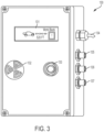
- FIGURE 3 provides a close-up view of an exemplary embodiment of a V-aware unit 130.
- the V-aware unit 130 may be a device that communicates with an encroachment unit to recognize a boundary limit of a work block.
- the V-aware unit 130 may comprise, on the outside, a display 131, an audible alarm 132, a program setting button 133, a power connection 134, a GPS connection 135, a rear antenna connection 136, and a front antenna connection 137.
- the V-aware unit 130 may further comprise internal components, such as processors, memories, transceivers, etc., that work with the external components.
- the display 131 may show a warning message to an operator.
- a volume of the audible alarm 132 may be configured higher or lower by turning the audible alarm 132.
- the audible alarm 132 may be a standard off-the-shelf piezo audible alarm with a baffle, which may be turned to increase or decrease volume. Audible alarming may also be turned on and off.
- the button 133 may be used to set, change, or program various settings of the V-aware unit 130.
- the power connection 134 may be wired to vehicle power, e.g., between 18 and 75 direct current (DC) volts, that is provided when the vehicle engine is started or the vehicle electronics are started.
- vehicle power e.g., between 18 and 75 direct current (DC) volts
- the V-aware unit 130 may have any suitable number of transceivers coupled to any suitable number of antennas.
- the two antenna connections 136 and 137 may be connected to coaxial cables, which in turn are connected to two antennas.
- the V-aware unit 130 may be used to mitigate potential accidents by informing the rail vehicle operator of potential safety rule violations.
- the V-aware unit 130 may be mounted inside the cab of multiple vehicles.
- the V-aware unit 130 may be installed where the display 131 is in clear view of the operator, or at any other appropriate position.
- a V-aware unit 130 located in the vehicle 114 may identify a safety rule violation based on a distance between the vehicle 114 and an encroachment unit located at about the boundary of Work Block 2 and Work Block 3.
- the display 131 of the V-aware unit 130 may show, in real time, a distance between the vehicle 114 and the closest encroachment unit 140.
- a calculated distance may be updated, intermittently or in real time, as the vehicle becomes closer to, or further away from, the closest encroachment unit 140.
- the V-aware unit 130 may calculate and display the distance between itself and an encroachment unit that is getting closer and closer.
- the display 131 may simultaneously display multiple distances (e.g., distances to a rear encroachment unit and to a front encroachment unit).
- a V-aware unit 130 may be used to determine distances between vehicles.
- the V-aware unit 130 on the vehicle 114 may be a first V-aware unit that may communicate with a second V-aware unit installed on another vehicle 116.
- the first V-aware unit may determine and display a distance between the rail vehicle 114 and the vehicle 116 based on the communications between them.
- the display 131 on the vehicle 114 may indicate a distance between itself and the closest vehicle either to the rear (e.g., the vehicle 112) or to the front (e.g., the vehicle 116).
- a V-aware unit 130 may be installed at a fixed location on the vehicle 114, and an encroachment unit 140 may be attached at a fixed position relative to a boundary limit of a work block (e.g., at the start of Work Block 3), determining distances between these objects may have equivalent forms. For example, if a distance between the V-aware unit 130 and the encroachment unit 140 is known, one may easily determine a distance between the vehicle 114 and the start of Work Block 3. A calculated distance may be adjusted depending on where the V-aware unit 130 is located on the vehicle 114, depending on a length of the vehicle 114, or depending on whether the rail vehicle 114 has equipment mounted or coupled to its front or rear that extends the length of the vehicle 114.
- the V-aware unit 130 may also issue visual alerts and/or audible alerts to the host operator when the vehicle 114 is approaching an end limit of a work block or another vehicle.
- Distances at which alarms are issued may be flexibly configured, such as 1000, 800, 600, 300, 200, 100, 75, 50, and 25 feet.
- the alarming distance may depend on a speed of the vehicle 114, which may be determined using a GPS module. For example, at higher speeds, the vehicle 114 may require a longer alarming distance to give sufficient time for the operator to act.
- a distance between a V-aware unit 130 and an encroachment unit 140 drops to or below a certain pre-determined threshold (e.g., 300 feet at high speeds, or 24 feet at low speeds).
- a certain pre-determined threshold e.g. 300 feet at high speeds, or 24 feet at low speeds
- alarming mechanisms may be triggered.
- the audible alarm 132 may sound continuously, informing the vehicle operator of a potential collision hazard.
- a V-aware unit 130 or an encroachment unit 140 may record and keep data logs.
- a violation of a safety rule by the rail vehicle may be identified by the V-aware unit 130, or the encroachment unit 140, or both.
- a memory device may store a data log at least when there is a violation of a safety rule.
- Stored data log may comprise information that indicates (1) a timestamp (e.g., date and time) of the violation, (2) an identification (ID) of the rail vehicle, and/or (3) the distance between the work block limit encroachment unit and the rail vehicle as determined at a time of the violation.
- the identification of the rail vehicle may be recorded in any suitable form as long as the rule-violating vehicle or its category can be identified.
- the date and time of each event may be saved in an onboard memory of the V-aware unit 130. Additional events may be logged when the operator presses a button or makes changes to configuration settings. Further, data logging may be continuous or triggered by violation events. Exemplary events that trigger data logging may include distance threshold (proximity of 1000', 600', 300', 75', 50', and 25'), configuration changes, and button presses by the operator. A unit may log the timestamp at which any of these events had occurred, along with information about the event itself.
- data that records the violation may be reported to an Operations Control Center ("OCC"), a command vehicle, or a supervisor that may be located away from the work site.
- OCC Operations Control Center
- Data may be transmitted wirelessly over GPS or cellular links. In dark territories where there are no GPS or cellular links, data may be transmitted to an OCC via radio communication links (e.g., at about 400 MHz).
- the unit may, alternatively or additionally, have transceivers that work near (at and close to) various frequencies such as 430 MHz, 220 MHz, 900 MHz, 2.4 GHz, global positioning system (GPS) frequencies, and cellular frequencies.
- GPS global positioning system
- Both a V-aware unit 130 or an encroachment unit 140 may be configured to have GPS antennas to communicate with an OCC. Rule violations may be reported to the OCC or a shift supervisor by the V-aware unit 130, or the encroachment unit 140, or both.
- the V-aware unit 130 may report the violation of a safety rule by sending out data that indicates a timestamp of the violation, an identification of the rail vehicle, and the distance between the work block limit encroachment unit and the rail vehicle as determined at a time of the violation. Reporting may take any suitable form, e.g., as an email or a text message.
- the encroachment unit 140 may issue a warning to nearby rail workers (e.g., the visual alarm 142 flashing a visible flash light and/or the audible alarm 148 sounding a loud alarm) in order to instruct them to get off the track.
- the encroachment unit 140 may also send a warning signal to one or more personal alert devices carried by the rail workers.
- Personal alert devices such as 121, 123, and 125 may each have an audible alarm and a LED warning light.
- the personal alert devices may be positioned on each of the workers in the vicinity of the track, thus warning them of the presence of an encroaching vehicle, which the workers might not otherwise notice due to their concentration on their work or due to the high volume of noise that may be occurring in the workers' vicinity.
- rail personnel including onsite workers and supervisors at an operations control center may adapt procedural changes. Note that the procedures and processes are given for example only, thus they may be modified (e.g., some steps omitted and some added) within the principles described herein.
- Mobile or fixed work zone personnel responsibilities may include using a V-aware unit, work block limit encroachment unit, portable warning horn and lights, and/or personal alert device in work blocks for various (e.g., all) types of track work.
- V-aware unit work block limit encroachment unit
- portable warning horn and lights portable warning horn and lights
- personal alert device in work blocks for various (e.g., all) types of track work.
- a shift supervisor may authorize and assemble work maintenance crew to perform track work.
- the supervisor may select (or elect himself as) a qualified person of the work crew as the designated work crew coordinator to manage activities with the OCC and to provide on-track safety for all members of the work crew. Only a designated qualified person may request and initiate a track work area and should comply with safety procedures, policies, and standards in order to ensure optimum safety to all personnel.
- work crew coordinator responsibilities may include the following:
- each individual crew member is responsible for following all on-track safety rules. All crew members may be required to adhere to all agency safety guidelines and personal protective equipment (PPE) requirements.
- PPE personal protective equipment
- responsibilities of operating a rail vehicle may include the following:
- OCC employee responsibilities may include the following:
- shift supervisor responsibilities may include the following:
- all crew members may be required to adhere to all agency safety guidelines and PPE requirements. Crew members shall not be permitted in the work block until given permission by the designated qualified person. All crew members may establish and maintain voice communication with designated flagger(s)/watchperson(s) /lookout(s). All crew members shall adhere to all designated safety personnel and warning devices and leave the work space when required. All crew members may be required to record any unauthorized violation of their work zone(s).
- the OCC prior to admitting maintenance vehicle(s) to mainline tracks, the OCC shall ensure that all vehicles are equipped with the work block/collision avoidance unit.
- the OCC may determine whether multiple maintenance vehicles may travel as one consistent unit or individually to the work zone. If maintenance vehicles are traveling as one consistent unit, OCC may inform the vehicle operators (e.g., absolute block, distance between vehicles, etc.) of the traveling procedures.
- the OCC may ensure that work crews already in the work zone(s) are notified of vehicle movement, and that required work crew members have their personal alert devices turned on.
- the present disclosure also describes a standard operating procedure for implementation and removal of a work block encroachment warning system for track crews.
- isolating individual work areas within a single work block may ensure safe working conditions for track workers from maintenance vehicles and potential human error.
- work block limit encroachment units may be used whenever there is a defined work area within a work block.
- a designated qualified person shall install the required work block limit encroachment units.
- Work block limit encroachment units may be installed at the end limit of each work area within the work block.
- the designated qualified person may establish contact with OCC and request track access by the following procedure:
- the designated qualified person shall turn on and install the work block limit encroachment units.
- the designated qualified person shall maintain communications with OCC and the work crew throughout the maintenance operation.
- removal of the work block encroachment units may follow certain procedures. Prior to removing the work block limit encroachment units the designated qualified person may establish contact with OCC and ask permission to remove work block limit encroachment units. Once OCC grants permission, the designated qualified person shall then remove the work block limit encroachment units and notify OCC when clear of the right of way.
- FIGURE 4 is a flowchart illustrating a process 400 for promoting railroad safety via rail communications.
- the process 400 may be implemented in a work block limit encroachment warning system (e.g., the system 150), which may comprise a first unit mounted on the railroad (e.g., the encroachment unit 140 located on a starting boundary of Work Block 3) and a second unit located in a rail vehicle (e.g., the V-aware unit 130 installed on the rail vehicle 114).
- the process 400 may be performed by various devices and personnel, and may not exhaustively list all steps necessary to use the system 150.
- a designated work crew coordinator may request permission from a control center to install an encroachment unit near a boundary limit of a work block.
- the encroachment unit may be magnetically coupled to one rail.
- the designated work crew coordinator may test the encroachment unit to confirm that it is turned on and operational.
- the encroachment unit may wirelessly communicate (e.g., using chirp signals over 2.4 GHz radio link) with a V-aware unit located on a moving vehicle.
- a distance between the encroachment unit and the V-aware unit may be determined based on at least some of the chirp signals. In an embodiment, when the distance drops to or below a threshold, a violation of work block safety rule by the moving rail vehicle is identified.
- the V-aware unit may display a warning message to an operator of the rail vehicle upon identification of the violation, wherein the warning message indicates the distance between the encroachment unit and the V-aware unit.
- the operator may elect to slow down or stop the rail vehicle after the operator sees the warning message. Audio alarms may also be sounded to alert the operator.
- the encroachment unit may issue at least one of visible warning, audible warning, and data signal warning receivable by personal alert devices to nearby rail workers.
- a data log may be recorded, by the encroachment unit, or by the V-aware unit, or both, when the violation of work block safety rule occurs.
- the data log comprises information that indicates a time of the violation, an identification of the rail vehicle, and a distance between the first unit and the second unit at the time of the violation.
- the violation may be reported to a control center, a command vehicle, or a supervisor, by sending the information.
- the designated work crew coordinator may remove the first unit with permission from the control center. After unit removal, the designated work crew coordinator may verify with the control center that the work zone has been marked as clear.
- FIGURE 5 is a schematic diagram illustrating a general-purpose computing device 500 that may represent various units or systems disclosed herein.
- the computing device 500 may be used as part of any of the V-aware units 130 and any of the encroachment units 140.
- the computing device 500 may comprise a processor 502 (which may be referred to as a central processor unit or CPU), one or more memory devices (e.g., including secondary storage 504, read only memory (ROM) 506, and random access memory (RAM) 508), one or more transceivers 510. Although illustrated as a single processor, the processor 502 is not so limited and may comprise multiple processors.
- the processor 502 may be a unit capable of data processing, such as one or more CPU chips, cores (e.g., a multi-core processor), field-programmable gate arrays (FPGAs), application specific integrated circuits (ASICs), digital signal processors (DSPs), or combinations thereof.
- the processor 502 may be implemented using hardware (e.g., circuitry) alone or a combination of software and hardware.
- the secondary storage 504 may be used for non-volatile storage of data and as an over-flow data storage device if the RAM 508 is not large enough to hold all working data.
- the secondary storage 504 may be used to store programs that are loaded into the RAM 508 when such programs are selected for execution.
- the ROM 506 may be used to store instructions and perhaps data that are read during program execution.
- the ROM 506 is a non-volatile memory device that typically has a small memory capacity relative to the larger memory capacity of the secondary storage 504.
- the RAM 508 is used to store volatile data and perhaps to store instructions. Access to both the ROM 506 and the RAM 508 is typically faster than to the secondary storage 504.
- a transceiver 510 may serve as an output and/or input device of the computing device 500. For example, if the transceiver 510 is acting as a transmitter, it may transmit data out of the computing device 500. If the transceiver 510 is acting as a receiver, it may receive data into the computing device 500.
- the transceiver 510 may work with cables or act as wireless antennas.
- the transceiver 510 may take the form of modems, Ethernet cards, universal serial bus (USB) interface cards, serial interfaces, wireless transceiver cards such as code division multiple access (CDMA), global system for mobile communications (GSM), long-term evolution (LTE), worldwide interoperability for microwave access (WiMAX), GPS, and/or other air interface protocol radio transceiver cards, and other well-known devices capable of wireless communications.
- the transceiver 510 may enable the processor 502 to communicate with other devices via radio, GPS, or cellular interfaces.
- I/O devices 512 may include output devices such as a screen display or speaker and input devices such as buttons and dial pads.
- a design that is still subject to frequent change may be preferred to be implemented in software, because re-spinning a hardware implementation is more expensive than re-spinning a software design.
- a design that is stable that will be produced in large volume may be preferred to be implemented in hardware, for example in an ASIC, because for large production runs the hardware implementation may be less expensive than the software implementation.
- a design may be developed and tested in a software form and later transformed, by well-known design rules, to an equivalent hardware implementation in an ASIC that hardwires the instructions of the software.
- a machine controlled by a new ASIC is a particular machine or apparatus, likewise a computer that has been programmed and/or loaded with executable instructions may be viewed as a particular machine or apparatus.
Landscapes
- Engineering & Computer Science (AREA)
- Mechanical Engineering (AREA)
- Business, Economics & Management (AREA)
- Emergency Management (AREA)
- Physics & Mathematics (AREA)
- General Physics & Mathematics (AREA)
- Human Computer Interaction (AREA)
- Train Traffic Observation, Control, And Security (AREA)
Claims (20)
- Arbeitsblockgrenzüberschreitungseinheit (140), die etwa an einer Randgrenze eines Arbeitsblocks an einer Bahnstrecke (100) eingesetzt ist, umfassend:einen oder mehrere Sendeempfänger, die dazu konfiguriert sind, drahtlos mit einer Kollisionsvermeidungseinheit (130) zu kommunizieren, die sich in einem Schienenfahrzeug (152) befindet, das sich in Richtung des Arbeitsblocks bewegt; undeinen Prozessor, der dazu konfiguriert ist, auf Grundlage der Kommunikation mit der Kollisionsvermeidungseinheit (130) einen Abstand zwischen der Einheit (140) für die Arbeitsblockgrenzüberschreitung und dem Schienenfahrzeug (152) zu bestimmen,dadurch gekennzeichnet, dass die Arbeitsblocküberschreitungseinheit (140) ferner eine Magnetmontageanordnung (146) umfasst, die dazu konfiguriert ist, magnetisch an eine Fahrschiene (102, 104) gekoppelt zu werden.
- Arbeitsblockgrenzüberschreitungseinheit nach Anspruch 1, wobei die Kommunikation mit der Kollisionsvermeidungseinheit (130) Senden und Empfangen von Chirp-Signalen in einem Funkfrequenzband etwa nahe 2,4 GHz umfasst und wobei der Abstand zwischen der Arbeitsblockgrenzüberschreitungseinheit (140) und dem Schienenfahrzeug (152) auf Grundlage der Chirp-Signale bestimmt wird.
- Arbeitsblockgrenzüberschreitungseinheit nach Anspruch 1, ferner umfassend mindestens eine von visuellen und akustischen Alarmkomponenten (142, 148), die dazu konfiguriert ist, eine Warnung an einen oder mehrere in der Nähe befindliche Schienenarbeiter auszugeben, wenn der Abstand zwischen der Arbeitsblockgrenzüberschreitungseinheit (140) und dem Schienenfahrzeug (152) auf oder unter einen vorab bestimmten Schwellenwert fällt.
- Arbeitsblockgrenzüberschreitungseinheit nach Anspruch 1, wobei der eine oder die mehreren Sendeempfänger ferner dazu konfiguriert sind, wenn der Abstand zwischen der Arbeitsblockgrenzüberschreitungseinheit (140) und dem Schienenfahrzeug (152) auf oder unter einen vorab bestimmten Schwellenwert fällt, Schienenarbeiter durch Übertragen von Signalen, die durch persönliche Alarmvorrichtungen, die von den Schienenarbeitern mitgeführt werden, empfangbar sind, zu warnen.
- Arbeitsblockgrenzüberschreitungseinheit nach Anspruch 1, ferner umfassend eine Speichervorrichtung, die dazu konfiguriert ist, zumindest dann ein Datenprotokoll zu speichern, wenn der Abstand zwischen der Arbeitsblockgrenzüberschreitungseinheit (140) und dem Schienenfahrzeug (152) auf oder unter einen vorab bestimmten Schwellenwert fällt, wodurch ein Verstoß gegen eine Sicherheitsregel durch einen Führer des Schienenfahrzeugs (152) angegeben wird, wobei das gespeicherte Datenprotokoll Informationen umfasst, die einen Zeitstempel des Verstoßes und eine Identifizierung des Schienenfahrzeugs (152) angeben.
- Arbeitsblockgrenzüberschreitungseinheit nach Anspruch 1, wobei ein Eintreten des Falls, dass der Abstand zwischen der Arbeitsblockgrenzüberschreitungseinheit (140) und dem Schienenfahrzeug (152) auf oder unter einen Schwellenwert fällt, einen Verstoß gegen eine Sicherheitsregel durch das Schienenfahrzeug (152) angibt und wobei der eine oder die mehreren Sendeempfänger ferner dazu konfiguriert sind, den Verstoß gegen die Sicherheitsregel durch Aussenden von Daten zu melden, die Folgendes angeben:einen Zeitstempel des Verstoßes;eine Identifizierung des Schienenfahrzeugs (152); undden Abstand zwischen der Arbeitsblockgrenzüberschreitungseinheit (140) und dem Schienenfahrzeug (152), wie zum Zeitpunkt des Verstoßes bestimmt.
- Arbeitsblockgrenzüberschreitungseinheit nach Anspruch 6, wobei die Daten, die den Verstoß identifizieren, über eine Funkkommunikationsverbindung an eine Betriebszentrale (operations control center - OCC) gesendet werden.
- System (150) zur Warnung vor Arbeitsblocküberschreitungen zur Verwendung im Eisenbahnbereich, umfassend:eine Arbeitsblockgrenzüberschreitungseinheit (140) gemäß Anspruch 1, die an eine Fahrschiene (102, 104) gekoppelt ist; undeine Kollisionsvermeidungseinheit (130), die dazu konfiguriert ist, an einem Schienenfahrzeug (152) angebracht zu sein, wobei die Kollisionsvermeidungseinheit (130) Folgendes umfasst:einen oder mehrere Sendeempfänger (510), die dazu konfiguriert sind, mit der Arbeitsblockgrenzüberschreitungseinheit (140) zu kommunizieren; undeinen Prozessor (502), der an den einen oder die mehreren Sendeempfänger (510) gekoppelt ist und dazu konfiguriert ist, auf Grundlage der Kommunikation eine Randgrenze eines Arbeitsblocks zu erkennen, die der Arbeitsblockgrenzüberschreitungseinheit (140) zugeordnet ist.
- System zur Warnung vor Arbeitsblocküberschreitungen nach Anspruch 8, wobei die Kommunikation mit der Arbeitsblockgrenzüberschreitungseinheit (140) Empfangen von Chirp-Signalen in einem Funkfrequenzband etwa nahe 2,4 GHz umfasst und wobei der Prozessor (502) ferner dazu konfiguriert ist, auf Grundlage der Chirp-Signale allgemein einen Abstand zwischen der Arbeitsblockgrenzüberschreitungseinheit (140) und dem Schienenfahrzeug (152) zur Erkennung der Randgrenze des Arbeitsblocks zu berechnen.
- System zur Warnung vor Arbeitsblocküberschreitungen nach Anspruch 8, wobei die Kollisionsvermeidungseinheit (130) ferner Folgendes umfasst:eine Anzeige (131), die dazu konfiguriert ist, den Abstand zwischen der Arbeitsblockgrenzüberschreitungseinheit (140) und dem Schienenfahrzeug (152) einem Führer des Schienenfahrzeugs (152) anzuzeigen; undmindestens eine von visuellen und akustischen Alarmkomponenten (132), die dazu konfiguriert ist, eine Warnung an den Führer auszugeben, wenn der Abstand zwischen der Arbeitsblockgrenzüberschreitungseinheit (140) und dem Schienenfahrzeug (152) auf oder unter einen vorab bestimmten Schwellenwert fällt.
- System zur Warnung vor Arbeitsblocküberschreitungen nach Anspruch 8, wobei die Arbeitsblockgrenzüberschreitungseinheit (140) über magnetische Kopplung entfernbar an einer Außenseite eines Stegs der Schiene befestigt ist und wobei die Arbeitsblockgrenzüberschreitungseinheit (140) dazu konfiguriert ist, eine Warnung an persönliche Alarmvorrichtungen auszugeben, die von Arbeitern in dem Arbeitsblock mitgeführt werden, wenn ein Abstand zwischen dem Schienenfahrzeug (152) und der Randgrenze des Arbeitsblocks unter einen vorab festgelegten Schwellenwert fällt.
- System zur Warnung vor Arbeitsblocküberschreitungen nach Anspruch 8, ferner umfassend eine Speichervorrichtung (504, 506, 508), die mit dem Prozessor (510) gekoppelt ist und dazu konfiguriert ist, ein Datenprotokoll zu speichern, wobei das Datenprotokoll Informationen umfasst, die eine oder mehrere Verstöße gegen die Regel durch das Schienenfahrzeug (152) identifizieren und wobei die Informationen einen Zeitstempel des Verstoßes gegen die Regel und einen Abstand zwischen dem Schienenfahrzeug (152) und der Randgrenze eines Arbeitsblocks zu einem Zeitpunkt des Verstoßes angeben.
- System zur Warnung vor Arbeitsblocküberschreitungen nach Anspruch 12, wobei der eine oder die mehreren Sendeempfänger (510) ferner dazu konfiguriert sind, die Informationen, die einen oder mehrere Verstöße gegen die Regel identifizieren, an eine Betriebszentrale (OCC) zu übertragen.
- System zur Warnung vor Arbeitsblocküberschreitungen nach Anspruch 8, wobei die Kollisionsvermeidungseinheit (130) eine erste Kollisionsvermeidungseinheit ist, die an einem ersten Schienenfahrzeug (114) angebracht ist und die ferner zu Folgendem konfiguriert ist:Kommunizieren mit einer zweiten Kollisionsvermeidungseinheit, die an einem zwischen Schienenfahrzeug (116) angebracht ist;Anzeigen eines Abstands zwischen dem ersten Schienenfahrzeug (114) und dem zweiten Schienenfahrzeug (116) auf Grundlage der Kommunikation mit der zweiten Kollisionsvermeidungseinheit durch einen Bildschirm an der ersten Kollisionsvermeidungseinheit.
- Verfahren zum Fördern der Eisenbahnsicherheit über Schienenkommunikation, wobei das Verfahren Folgendes umfasst:magnetisches Koppeln einer ersten Einheit, die einem Arbeitsblock zugeordnet ist, an eine Fahrschiene; unddrahtloses Kommunizieren zwischen der ersten Einheit und einer zweiten Einheit, die sich in einem Schienenfahrzeug befindet, um einen Abstand zwischen der ersten Einheit und der zweiten Einheit zu bestimmen und einen Verstoß gegen eine Arbeitsblocksicherheitsregel durch das Schienenfahrzeug auf Grundlage des bestimmten Abstands zu bestimmen.
- Verfahren nach Anspruch 15, wobei die erste Einheit etwa an einem Ende des Arbeitsblocks positioniert ist, wobei sich das Schienenfahrzeug dem Ende des Arbeitsblocks von außerhalb des Arbeitsblocks nähert, wobei die Kommunikation zwischen der ersten Einheit und der zweiten Einheit Senden und Empfangen von Chirp-Signalen in einem Funkfrequenzband etwa nahe 2,4 GHz zwischen der ersten Einheit und der zweiten Einheit umfasst, wobei das Verfahren ferner Bestimmen eines Abstands zwischen der ersten Einheit und der zweiten Einheit auf Grundlage der Chirp-Signale umfasst und wobei der Verstoß gegen die Arbeitsblocksicherheitsregel identifiziert wird, wenn der Abstand zwischen der ersten Einheit und der zweiten Einheit auf oder unter einen Schwellenwert fällt.
- Verfahren nach Anspruch 16, ferner umfassend:Anzeigen einer Warnmeldung für einen Führer des Schienenfahrzeugs auf einer Anzeige der zweiten Einheit bei Identifizierung des Verstoßes, wobei die Warnmeldung den Abstand zwischen der ersten Einheit und der zweiten Einheit angibt; undAnhalten des Schienenfahrzeugs durch den Führer nach dem Anzeigen der Warnmeldung.
- Verfahren nach Anspruch 15, ferner umfassend Ausgeben zumindest einer visuellen Warnung, akustischen Warnung und einer Datensignalwarnung, die von persönlichen Alarmvorrichtungen empfangbar sind, an in der Nähe befindliche Schienenarbeiter, damit die Schienenarbeiter die Schienen verlassen, wobei das Ausgeben von Warnungen furch die erste Einheit bei der Identifizierung des Verstoßes durchgeführt wird.
- Verfahren nach Anspruch 15, ferner umfassend:Aufzeichnen eines Datenprotokolls, zumindest wenn der Verstoß gegen die Arbeitsblocksicherheitsregel auftritt, wobei das Datenprotokoll Informationen umfasst, die einen Zeitpunkt des Verstoßes, eine Identifizierung des Schienenfahrzeugs und einen Abstand zwischen der ersten Einheit und der zweiten Einheit zum Zeitpunkt des Verstoßes angeben; undMelden des Verstoßes an eine Betriebszentrale durch Senden der Informationen.
- Verfahren nach Anspruch 15, ferner umfassend:vor dem Betreten des Arbeitsblocks durch Schienenarbeiter, Anfordern einer Erlaubnis von einer Betriebszentrale zur Anbringung der ersten Einheit durch einen festgelegten Koordinator des Arbeitsteams;Testen der ersten Einheit durch den festgelegten Koordinator des Arbeitsteams, um zu bestätigen, dass die erste Einheit eingeschaltet und betriebsbereit ist;während oder nach Schienenarbeiten in dem Arbeitsblock Melden des Verstoßes gegen die Arbeitsblocksicherheitsregel an die Betriebszentrale durch mindestens eines der folgenden Personalmitglieder: den festgelegten Koordinator des Arbeitsteams, die Schienenarbeiter und einen Führer des Schienenfahrzeugs; undnach der Schienenarbeit in dem Arbeitsblock Entfernen der ersten Einheit durch den festgelegten Koordinator des Arbeitsteams mit Erlaubnis von der Betriebszentrale.
Priority Applications (1)
| Application Number | Priority Date | Filing Date | Title |
|---|---|---|---|
| EP24163063.1A EP4410633A3 (de) | 2014-10-03 | 2015-10-02 | System zur warnung vor arbeitsblockübergriff |
Applications Claiming Priority (2)
| Application Number | Priority Date | Filing Date | Title |
|---|---|---|---|
| US201462071817P | 2014-10-03 | 2014-10-03 | |
| PCT/US2015/053697 WO2016054492A1 (en) | 2014-10-03 | 2015-10-02 | Work block encroachment warning system |
Related Child Applications (1)
| Application Number | Title | Priority Date | Filing Date |
|---|---|---|---|
| EP24163063.1A Division EP4410633A3 (de) | 2014-10-03 | 2015-10-02 | System zur warnung vor arbeitsblockübergriff |
Publications (4)
| Publication Number | Publication Date |
|---|---|
| EP3201061A1 EP3201061A1 (de) | 2017-08-09 |
| EP3201061A4 EP3201061A4 (de) | 2018-06-27 |
| EP3201061C0 EP3201061C0 (de) | 2024-03-13 |
| EP3201061B1 true EP3201061B1 (de) | 2024-03-13 |
Family
ID=55631595
Family Applications (2)
| Application Number | Title | Priority Date | Filing Date |
|---|---|---|---|
| EP15845620.2A Active EP3201061B1 (de) | 2014-10-03 | 2015-10-02 | System zur warnung vor arbeitsblockübergriffen |
| EP24163063.1A Pending EP4410633A3 (de) | 2014-10-03 | 2015-10-02 | System zur warnung vor arbeitsblockübergriff |
Family Applications After (1)
| Application Number | Title | Priority Date | Filing Date |
|---|---|---|---|
| EP24163063.1A Pending EP4410633A3 (de) | 2014-10-03 | 2015-10-02 | System zur warnung vor arbeitsblockübergriff |
Country Status (7)
| Country | Link |
|---|---|
| US (4) | US9902411B2 (de) |
| EP (2) | EP3201061B1 (de) |
| AU (1) | AU2015327990B2 (de) |
| CA (1) | CA2962820A1 (de) |
| MX (1) | MX381496B (de) |
| RU (1) | RU2017115558A (de) |
| WO (1) | WO2016054492A1 (de) |
Families Citing this family (17)
| Publication number | Priority date | Publication date | Assignee | Title |
|---|---|---|---|---|
| AU2015327990B2 (en) * | 2014-10-03 | 2020-09-24 | Harsco Technologies LLC | Work block encroachment warning system |
| US11492027B2 (en) * | 2015-03-23 | 2022-11-08 | Metrom Rail, Llc | Methods and systems for worker protection system with ultra-wideband (UWB) based anchor network |
| WO2017015110A1 (en) | 2015-07-17 | 2017-01-26 | Harsco Technologies LLC | Rail warning system and method |
| US10106079B2 (en) * | 2015-09-24 | 2018-10-23 | Miller Felpax | System and method for fault tolerant roadway worker safety system |
| US10518792B2 (en) * | 2015-09-24 | 2019-12-31 | Miller Felpax Corporation | Roadway worker safety system and methods of warning |
| DE102015218965A1 (de) * | 2015-09-30 | 2017-03-30 | Siemens Aktiengesellschaft | Sicherungsverfahren und Sicherungssystem für ein Gleisstreckennetz |
| DE102015218987A1 (de) * | 2015-09-30 | 2017-03-30 | Siemens Aktiengesellschaft | Sicherungsverfahren für ein Gleisstreckennetz |
| US20180099684A1 (en) * | 2016-10-10 | 2018-04-12 | Westinghouse Air Brake Technologies Corporation | System, method, and apparatus for verifying railroad work zone instructions |
| US11639188B2 (en) * | 2016-10-10 | 2023-05-02 | Westinghouse Air Brake Technologies Corporation | Work zone instruction verification system |
| US20200111360A1 (en) * | 2018-10-04 | 2020-04-09 | Harsco Technologies LLC | Train detector for embedded rail |
| US10789838B2 (en) * | 2018-10-11 | 2020-09-29 | Toyota Research Institute, Inc. | Dynamically updating ultra-wide band road markers |
| US10841777B1 (en) * | 2018-11-15 | 2020-11-17 | Robert Steven ALLEN | Professional qualification tracking and management system and method |
| US11170642B2 (en) | 2019-03-28 | 2021-11-09 | Stc, Inc. | Systems and methods for pacing a mass transit vehicle |
| NL2024146B1 (en) * | 2019-11-01 | 2021-07-19 | Build Connected B V | Precise placement of a sensor device on a rail track |
| US12600390B2 (en) | 2021-08-03 | 2026-04-14 | Miller Felpax Corporation | Railyard train detection and early warning system |
| CN115497288A (zh) * | 2022-09-06 | 2022-12-20 | 玺大建设工程有限公司 | 一种高速公路养护施工智慧管理预警方法、装置及系统 |
| WO2024072674A1 (en) * | 2022-09-26 | 2024-04-04 | Miller Felpax Corporation | Early warning system for shove track protection |
Citations (1)
| Publication number | Priority date | Publication date | Assignee | Title |
|---|---|---|---|---|
| US6471162B1 (en) * | 1991-02-04 | 2002-10-29 | Eva Signal Corporation | Railroad maintenance-of-way personnel warning system apparatus and method therefor |
Family Cites Families (17)
| Publication number | Priority date | Publication date | Assignee | Title |
|---|---|---|---|---|
| DE4428784A1 (de) | 1994-08-13 | 1996-02-15 | Ee Signals Gmbh & Co Kg | Verfahren zur Erfassung von Gefahrenquellen |
| US7075427B1 (en) | 1996-01-12 | 2006-07-11 | Eva Signal Corporation | Traffic warning system |
| US5924651A (en) | 1997-03-26 | 1999-07-20 | Penza; George Gregory | Tactile and audible warning system for railroad workers |
| US6232887B1 (en) | 1998-04-29 | 2001-05-15 | Joseph E. Carson | Warning systems |
| US6145792A (en) * | 1998-04-29 | 2000-11-14 | Penza; George Gregory | Railroad worker warning system for train conductors |
| RU2357886C2 (ru) * | 2003-05-22 | 2009-06-10 | Дженерал Электрик Компани | Способ и система управления локомотивами |
| DE102004053163A1 (de) * | 2003-11-26 | 2005-06-30 | Ee-Signals Gmbh & Co. Kg | Individual-Warngerät eines Rottenwarnsystems |
| US7624952B1 (en) * | 2006-04-04 | 2009-12-01 | Bartek Peter M | Safety system for railroad personnel |
| JP5292161B2 (ja) | 2008-05-27 | 2013-09-18 | 公益財団法人鉄道総合技術研究所 | レール用部材取付治具 |
| DE102008046565A1 (de) | 2008-09-10 | 2010-03-18 | Siemens Aktiengesellschaft | Vorrichtung und Verfahren zur Detektion eines Zuges |
| US8344877B2 (en) | 2009-07-07 | 2013-01-01 | Bombardier Transportation Gmbh | Track worker safety system |
| JP5868607B2 (ja) * | 2011-03-31 | 2016-02-24 | 東日本旅客鉄道株式会社 | 鉄道用警報発生システム |
| US8812227B2 (en) | 2011-05-19 | 2014-08-19 | Metrom Rail, Llc | Collision avoidance system for rail line vehicles |
| US9047781B2 (en) | 2011-05-31 | 2015-06-02 | Georgia Tech Research Corporation | Safety zone detection, enforcement and alarm system and related methods |
| US9542852B2 (en) * | 2011-10-14 | 2017-01-10 | Stc, Inc. | Mass transit safety notification system and device |
| US20130300551A1 (en) * | 2012-05-10 | 2013-11-14 | Steven J. Weber | Object proximity system |
| AU2015327990B2 (en) * | 2014-10-03 | 2020-09-24 | Harsco Technologies LLC | Work block encroachment warning system |
-
2015
- 2015-10-02 AU AU2015327990A patent/AU2015327990B2/en active Active
- 2015-10-02 RU RU2017115558A patent/RU2017115558A/ru not_active Application Discontinuation
- 2015-10-02 MX MX2017004326A patent/MX381496B/es unknown
- 2015-10-02 US US14/873,609 patent/US9902411B2/en active Active
- 2015-10-02 WO PCT/US2015/053697 patent/WO2016054492A1/en not_active Ceased
- 2015-10-02 CA CA2962820A patent/CA2962820A1/en active Pending
- 2015-10-02 EP EP15845620.2A patent/EP3201061B1/de active Active
- 2015-10-02 EP EP24163063.1A patent/EP4410633A3/de active Pending
-
2017
- 2017-10-30 US US15/797,330 patent/US10752272B2/en active Active
-
2020
- 2020-08-24 US US16/947,908 patent/US11708099B2/en active Active
-
2023
- 2023-07-24 US US18/357,897 patent/US20240199098A1/en active Pending
Patent Citations (1)
| Publication number | Priority date | Publication date | Assignee | Title |
|---|---|---|---|---|
| US6471162B1 (en) * | 1991-02-04 | 2002-10-29 | Eva Signal Corporation | Railroad maintenance-of-way personnel warning system apparatus and method therefor |
Also Published As
| Publication number | Publication date |
|---|---|
| EP4410633A3 (de) | 2024-09-11 |
| CA2962820A1 (en) | 2016-04-07 |
| US9902411B2 (en) | 2018-02-27 |
| EP3201061A1 (de) | 2017-08-09 |
| MX2017004326A (es) | 2017-11-15 |
| US20240199098A1 (en) | 2024-06-20 |
| US10752272B2 (en) | 2020-08-25 |
| EP4410633A2 (de) | 2024-08-07 |
| US20160096539A1 (en) | 2016-04-07 |
| EP3201061C0 (de) | 2024-03-13 |
| US11708099B2 (en) | 2023-07-25 |
| RU2017115558A (ru) | 2018-11-08 |
| US20210070331A1 (en) | 2021-03-11 |
| AU2015327990B2 (en) | 2020-09-24 |
| EP3201061A4 (de) | 2018-06-27 |
| RU2017115558A3 (de) | 2019-05-07 |
| MX381496B (es) | 2025-03-12 |
| AU2015327990A1 (en) | 2017-04-20 |
| US20180043913A1 (en) | 2018-02-15 |
| WO2016054492A1 (en) | 2016-04-07 |
Similar Documents
| Publication | Publication Date | Title |
|---|---|---|
| US20240199098A1 (en) | Work block encroachment warning system | |
| US10814892B2 (en) | V-aware end of train device | |
| AU2021202756B2 (en) | Failsafe rail mounted shunt device | |
| US10029716B2 (en) | Mass transit safety notification system and device | |
| US20080169939A1 (en) | Early warning control system for vehicular crossing safety | |
| CA2852234C (en) | Mass transit safety notification system and device | |
| US8630758B2 (en) | Method and apparatus for safety protocol verification, control and management | |
| KR101709098B1 (ko) | 열차 운행 정보 제공 시스템 및 방법 | |
| US12515720B2 (en) | Signal box controlled crew warning system | |
| JP6448931B2 (ja) | 衝突防止システム | |
| EP4249347A1 (de) | System zur warnung von gleisarbeitern vor sich auf einem nachbargleis nährenden zügen | |
| KR102194619B1 (ko) | 경광등 알림 시스템 | |
| KR20160007996A (ko) | 철도선로 방호구간 운영시스템 및 방법 | |
| TR201514352A2 (tr) | Demiryolu araçları için yaklaşım algılama ve bir çeşit uyarı sistemi | |
| CZ27499U1 (cs) | Zařízení pro zvýšení pasivní bezpečnosti na železničních přejezdech zabezpečených výstražným světelným zařízením |
Legal Events
| Date | Code | Title | Description |
|---|---|---|---|
| STAA | Information on the status of an ep patent application or granted ep patent |
Free format text: STATUS: THE INTERNATIONAL PUBLICATION HAS BEEN MADE |
|
| PUAI | Public reference made under article 153(3) epc to a published international application that has entered the european phase |
Free format text: ORIGINAL CODE: 0009012 |
|
| STAA | Information on the status of an ep patent application or granted ep patent |
Free format text: STATUS: REQUEST FOR EXAMINATION WAS MADE |
|
| 17P | Request for examination filed |
Effective date: 20170405 |
|
| AK | Designated contracting states |
Kind code of ref document: A1 Designated state(s): AL AT BE BG CH CY CZ DE DK EE ES FI FR GB GR HR HU IE IS IT LI LT LU LV MC MK MT NL NO PL PT RO RS SE SI SK SM TR |
|
| AX | Request for extension of the european patent |
Extension state: BA ME |
|
| DAV | Request for validation of the european patent (deleted) | ||
| DAX | Request for extension of the european patent (deleted) | ||
| A4 | Supplementary search report drawn up and despatched |
Effective date: 20180530 |
|
| RIC1 | Information provided on ipc code assigned before grant |
Ipc: B61L 25/02 20060101ALI20180522BHEP Ipc: B61L 23/06 20060101AFI20180522BHEP |
|
| STAA | Information on the status of an ep patent application or granted ep patent |
Free format text: STATUS: EXAMINATION IS IN PROGRESS |
|
| 17Q | First examination report despatched |
Effective date: 20210317 |
|
| GRAP | Despatch of communication of intention to grant a patent |
Free format text: ORIGINAL CODE: EPIDOSNIGR1 |
|
| STAA | Information on the status of an ep patent application or granted ep patent |
Free format text: STATUS: GRANT OF PATENT IS INTENDED |
|
| INTG | Intention to grant announced |
Effective date: 20230926 |
|
| GRAS | Grant fee paid |
Free format text: ORIGINAL CODE: EPIDOSNIGR3 |
|
| GRAA | (expected) grant |
Free format text: ORIGINAL CODE: 0009210 |
|
| STAA | Information on the status of an ep patent application or granted ep patent |
Free format text: STATUS: THE PATENT HAS BEEN GRANTED |
|
| AK | Designated contracting states |
Kind code of ref document: B1 Designated state(s): AL AT BE BG CH CY CZ DE DK EE ES FI FR GB GR HR HU IE IS IT LI LT LU LV MC MK MT NL NO PL PT RO RS SE SI SK SM TR |
|
| REG | Reference to a national code |
Ref country code: GB Ref legal event code: FG4D |
|
| REG | Reference to a national code |
Ref country code: CH Ref legal event code: EP |
|
| REG | Reference to a national code |
Ref country code: DE Ref legal event code: R096 Ref document number: 602015087939 Country of ref document: DE |
|
| REG | Reference to a national code |
Ref country code: IE Ref legal event code: FG4D |
|
| U01 | Request for unitary effect filed |
Effective date: 20240412 |
|
| U07 | Unitary effect registered |
Designated state(s): AT BE BG DE DK EE FI FR IT LT LU LV MT NL PT SE SI Effective date: 20240429 |
|
| PG25 | Lapsed in a contracting state [announced via postgrant information from national office to epo] |
Ref country code: GR Free format text: LAPSE BECAUSE OF FAILURE TO SUBMIT A TRANSLATION OF THE DESCRIPTION OR TO PAY THE FEE WITHIN THE PRESCRIBED TIME-LIMIT Effective date: 20240614 |
|
| PG25 | Lapsed in a contracting state [announced via postgrant information from national office to epo] |
Ref country code: RS Free format text: LAPSE BECAUSE OF FAILURE TO SUBMIT A TRANSLATION OF THE DESCRIPTION OR TO PAY THE FEE WITHIN THE PRESCRIBED TIME-LIMIT Effective date: 20240613 Ref country code: HR Free format text: LAPSE BECAUSE OF FAILURE TO SUBMIT A TRANSLATION OF THE DESCRIPTION OR TO PAY THE FEE WITHIN THE PRESCRIBED TIME-LIMIT Effective date: 20240313 |
|
| PG25 | Lapsed in a contracting state [announced via postgrant information from national office to epo] |
Ref country code: ES Free format text: LAPSE BECAUSE OF FAILURE TO SUBMIT A TRANSLATION OF THE DESCRIPTION OR TO PAY THE FEE WITHIN THE PRESCRIBED TIME-LIMIT Effective date: 20240313 |
|
| PG25 | Lapsed in a contracting state [announced via postgrant information from national office to epo] |
Ref country code: RS Free format text: LAPSE BECAUSE OF FAILURE TO SUBMIT A TRANSLATION OF THE DESCRIPTION OR TO PAY THE FEE WITHIN THE PRESCRIBED TIME-LIMIT Effective date: 20240613 Ref country code: NO Free format text: LAPSE BECAUSE OF FAILURE TO SUBMIT A TRANSLATION OF THE DESCRIPTION OR TO PAY THE FEE WITHIN THE PRESCRIBED TIME-LIMIT Effective date: 20240613 Ref country code: HR Free format text: LAPSE BECAUSE OF FAILURE TO SUBMIT A TRANSLATION OF THE DESCRIPTION OR TO PAY THE FEE WITHIN THE PRESCRIBED TIME-LIMIT Effective date: 20240313 Ref country code: GR Free format text: LAPSE BECAUSE OF FAILURE TO SUBMIT A TRANSLATION OF THE DESCRIPTION OR TO PAY THE FEE WITHIN THE PRESCRIBED TIME-LIMIT Effective date: 20240614 Ref country code: ES Free format text: LAPSE BECAUSE OF FAILURE TO SUBMIT A TRANSLATION OF THE DESCRIPTION OR TO PAY THE FEE WITHIN THE PRESCRIBED TIME-LIMIT Effective date: 20240313 |
|
| PG25 | Lapsed in a contracting state [announced via postgrant information from national office to epo] |
Ref country code: IS Free format text: LAPSE BECAUSE OF FAILURE TO SUBMIT A TRANSLATION OF THE DESCRIPTION OR TO PAY THE FEE WITHIN THE PRESCRIBED TIME-LIMIT Effective date: 20240713 |
|
| PG25 | Lapsed in a contracting state [announced via postgrant information from national office to epo] |
Ref country code: SM Free format text: LAPSE BECAUSE OF FAILURE TO SUBMIT A TRANSLATION OF THE DESCRIPTION OR TO PAY THE FEE WITHIN THE PRESCRIBED TIME-LIMIT Effective date: 20240313 |
|
| PG25 | Lapsed in a contracting state [announced via postgrant information from national office to epo] |
Ref country code: CZ Free format text: LAPSE BECAUSE OF FAILURE TO SUBMIT A TRANSLATION OF THE DESCRIPTION OR TO PAY THE FEE WITHIN THE PRESCRIBED TIME-LIMIT Effective date: 20240313 |
|
| PG25 | Lapsed in a contracting state [announced via postgrant information from national office to epo] |
Ref country code: PL Free format text: LAPSE BECAUSE OF FAILURE TO SUBMIT A TRANSLATION OF THE DESCRIPTION OR TO PAY THE FEE WITHIN THE PRESCRIBED TIME-LIMIT Effective date: 20240313 |
|
| PG25 | Lapsed in a contracting state [announced via postgrant information from national office to epo] |
Ref country code: SK Free format text: LAPSE BECAUSE OF FAILURE TO SUBMIT A TRANSLATION OF THE DESCRIPTION OR TO PAY THE FEE WITHIN THE PRESCRIBED TIME-LIMIT Effective date: 20240313 |
|
| PG25 | Lapsed in a contracting state [announced via postgrant information from national office to epo] |
Ref country code: SM Free format text: LAPSE BECAUSE OF FAILURE TO SUBMIT A TRANSLATION OF THE DESCRIPTION OR TO PAY THE FEE WITHIN THE PRESCRIBED TIME-LIMIT Effective date: 20240313 Ref country code: SK Free format text: LAPSE BECAUSE OF FAILURE TO SUBMIT A TRANSLATION OF THE DESCRIPTION OR TO PAY THE FEE WITHIN THE PRESCRIBED TIME-LIMIT Effective date: 20240313 Ref country code: RO Free format text: LAPSE BECAUSE OF FAILURE TO SUBMIT A TRANSLATION OF THE DESCRIPTION OR TO PAY THE FEE WITHIN THE PRESCRIBED TIME-LIMIT Effective date: 20240313 Ref country code: PL Free format text: LAPSE BECAUSE OF FAILURE TO SUBMIT A TRANSLATION OF THE DESCRIPTION OR TO PAY THE FEE WITHIN THE PRESCRIBED TIME-LIMIT Effective date: 20240313 Ref country code: IS Free format text: LAPSE BECAUSE OF FAILURE TO SUBMIT A TRANSLATION OF THE DESCRIPTION OR TO PAY THE FEE WITHIN THE PRESCRIBED TIME-LIMIT Effective date: 20240713 Ref country code: CZ Free format text: LAPSE BECAUSE OF FAILURE TO SUBMIT A TRANSLATION OF THE DESCRIPTION OR TO PAY THE FEE WITHIN THE PRESCRIBED TIME-LIMIT Effective date: 20240313 |
|
| REG | Reference to a national code |
Ref country code: DE Ref legal event code: R097 Ref document number: 602015087939 Country of ref document: DE |
|
| PLBE | No opposition filed within time limit |
Free format text: ORIGINAL CODE: 0009261 |
|
| STAA | Information on the status of an ep patent application or granted ep patent |
Free format text: STATUS: NO OPPOSITION FILED WITHIN TIME LIMIT |
|
| U21 | Renewal fee for the european patent with unitary effect paid with additional fee |
Year of fee payment: 10 Effective date: 20241227 |
|
| 26N | No opposition filed |
Effective date: 20241216 |
|
| REG | Reference to a national code |
Ref country code: CH Ref legal event code: PL |
|
| GBPC | Gb: european patent ceased through non-payment of renewal fee |
Effective date: 20241002 |
|
| PG25 | Lapsed in a contracting state [announced via postgrant information from national office to epo] |
Ref country code: MC Free format text: LAPSE BECAUSE OF FAILURE TO SUBMIT A TRANSLATION OF THE DESCRIPTION OR TO PAY THE FEE WITHIN THE PRESCRIBED TIME-LIMIT Effective date: 20240313 |
|
| PG25 | Lapsed in a contracting state [announced via postgrant information from national office to epo] |
Ref country code: GB Free format text: LAPSE BECAUSE OF NON-PAYMENT OF DUE FEES Effective date: 20241002 |
|
| PG25 | Lapsed in a contracting state [announced via postgrant information from national office to epo] |
Ref country code: CH Free format text: LAPSE BECAUSE OF NON-PAYMENT OF DUE FEES Effective date: 20241031 |
|
| PG25 | Lapsed in a contracting state [announced via postgrant information from national office to epo] |
Ref country code: IE Free format text: LAPSE BECAUSE OF NON-PAYMENT OF DUE FEES Effective date: 20241002 |
|
| U20 | Renewal fee for the european patent with unitary effect paid |
Year of fee payment: 11 Effective date: 20251027 |
|
| PG25 | Lapsed in a contracting state [announced via postgrant information from national office to epo] |
Ref country code: CY Free format text: LAPSE BECAUSE OF FAILURE TO SUBMIT A TRANSLATION OF THE DESCRIPTION OR TO PAY THE FEE WITHIN THE PRESCRIBED TIME-LIMIT; INVALID AB INITIO Effective date: 20151002 |
|
| PG25 | Lapsed in a contracting state [announced via postgrant information from national office to epo] |
Ref country code: HU Free format text: LAPSE BECAUSE OF FAILURE TO SUBMIT A TRANSLATION OF THE DESCRIPTION OR TO PAY THE FEE WITHIN THE PRESCRIBED TIME-LIMIT; INVALID AB INITIO Effective date: 20151002 |