EP3201089B1 - Intelligente fahrgastserviceeinheit - Google Patents
Intelligente fahrgastserviceeinheit Download PDFInfo
- Publication number
- EP3201089B1 EP3201089B1 EP15846009.7A EP15846009A EP3201089B1 EP 3201089 B1 EP3201089 B1 EP 3201089B1 EP 15846009 A EP15846009 A EP 15846009A EP 3201089 B1 EP3201089 B1 EP 3201089B1
- Authority
- EP
- European Patent Office
- Prior art keywords
- service unit
- passenger service
- speaker
- passenger
- power
- Prior art date
- Legal status (The legal status is an assumption and is not a legal conclusion. Google has not performed a legal analysis and makes no representation as to the accuracy of the status listed.)
- Active
Links
Images


Classifications
-
- H—ELECTRICITY
- H04—ELECTRIC COMMUNICATION TECHNIQUE
- H04R—LOUDSPEAKERS, MICROPHONES, GRAMOPHONE PICK-UPS OR LIKE ACOUSTIC ELECTROMECHANICAL TRANSDUCERS; ELECTRIC HEARING AIDS; PUBLIC ADDRESS SYSTEMS
- H04R1/00—Details of transducers, loudspeakers or microphones
- H04R1/02—Casings; Cabinets ; Supports therefor; Mountings therein
- H04R1/028—Casings; Cabinets ; Supports therefor; Mountings therein associated with devices performing functions other than acoustics, e.g. electric candles
-
- B—PERFORMING OPERATIONS; TRANSPORTING
- B64—AIRCRAFT; AVIATION; COSMONAUTICS
- B64D—EQUIPMENT FOR FITTING IN OR TO AIRCRAFT; FLIGHT SUITS; PARACHUTES; ARRANGEMENT OR MOUNTING OF POWER PLANTS OR PROPULSION TRANSMISSIONS IN AIRCRAFT
- B64D11/00—Passenger or crew accommodation; Flight-deck installations not otherwise provided for
- B64D11/0015—Arrangements for entertainment or communications, e.g. radio, television
- B64D11/00155—Individual entertainment or communication system remote controls therefor, located in or connected to seat components, e.g. to seat back or arm rest
-
- F—MECHANICAL ENGINEERING; LIGHTING; HEATING; WEAPONS; BLASTING
- F21—LIGHTING
- F21V—FUNCTIONAL FEATURES OR DETAILS OF LIGHTING DEVICES OR SYSTEMS THEREOF; STRUCTURAL COMBINATIONS OF LIGHTING DEVICES WITH OTHER ARTICLES, NOT OTHERWISE PROVIDED FOR
- F21V33/00—Structural combinations of lighting devices with other articles, not otherwise provided for
- F21V33/0004—Personal or domestic articles
- F21V33/0052—Audio or video equipment, e.g. televisions, telephones, cameras or computers; Remote control devices therefor
- F21V33/0056—Audio equipment, e.g. music instruments, radios or speakers
-
- H—ELECTRICITY
- H04—ELECTRIC COMMUNICATION TECHNIQUE
- H04R—LOUDSPEAKERS, MICROPHONES, GRAMOPHONE PICK-UPS OR LIKE ACOUSTIC ELECTROMECHANICAL TRANSDUCERS; ELECTRIC HEARING AIDS; PUBLIC ADDRESS SYSTEMS
- H04R1/00—Details of transducers, loudspeakers or microphones
- H04R1/20—Arrangements for obtaining desired frequency or directional characteristics
- H04R1/22—Arrangements for obtaining desired frequency or directional characteristics for obtaining desired frequency characteristic only
- H04R1/28—Transducer mountings or enclosures modified by provision of mechanical or acoustic impedances, e.g. resonator, damping means
-
- B—PERFORMING OPERATIONS; TRANSPORTING
- B64—AIRCRAFT; AVIATION; COSMONAUTICS
- B64D—EQUIPMENT FOR FITTING IN OR TO AIRCRAFT; FLIGHT SUITS; PARACHUTES; ARRANGEMENT OR MOUNTING OF POWER PLANTS OR PROPULSION TRANSMISSIONS IN AIRCRAFT
- B64D11/00—Passenger or crew accommodation; Flight-deck installations not otherwise provided for
- B64D2011/0053—Cabin passenger reading lights
-
- B—PERFORMING OPERATIONS; TRANSPORTING
- B64—AIRCRAFT; AVIATION; COSMONAUTICS
- B64D—EQUIPMENT FOR FITTING IN OR TO AIRCRAFT; FLIGHT SUITS; PARACHUTES; ARRANGEMENT OR MOUNTING OF POWER PLANTS OR PROPULSION TRANSMISSIONS IN AIRCRAFT
- B64D45/00—Aircraft indicators or protectors not otherwise provided for
- B64D2045/007—Indicators or signs in the cabin, e.g. exit signs or seat numbering
-
- B—PERFORMING OPERATIONS; TRANSPORTING
- B64—AIRCRAFT; AVIATION; COSMONAUTICS
- B64D—EQUIPMENT FOR FITTING IN OR TO AIRCRAFT; FLIGHT SUITS; PARACHUTES; ARRANGEMENT OR MOUNTING OF POWER PLANTS OR PROPULSION TRANSMISSIONS IN AIRCRAFT
- B64D2231/00—Emergency oxygen systems
- B64D2231/02—Supply or distribution systems
- B64D2231/025—Oxygen masks; Mask storages; Features related to mask deployment
-
- H—ELECTRICITY
- H04—ELECTRIC COMMUNICATION TECHNIQUE
- H04R—LOUDSPEAKERS, MICROPHONES, GRAMOPHONE PICK-UPS OR LIKE ACOUSTIC ELECTROMECHANICAL TRANSDUCERS; ELECTRIC HEARING AIDS; PUBLIC ADDRESS SYSTEMS
- H04R2499/00—Aspects covered by H04R or H04S not otherwise provided for in their subgroups
- H04R2499/10—General applications
- H04R2499/13—Acoustic transducers and sound field adaptation in vehicles
-
- Y—GENERAL TAGGING OF NEW TECHNOLOGICAL DEVELOPMENTS; GENERAL TAGGING OF CROSS-SECTIONAL TECHNOLOGIES SPANNING OVER SEVERAL SECTIONS OF THE IPC; TECHNICAL SUBJECTS COVERED BY FORMER USPC CROSS-REFERENCE ART COLLECTIONS [XRACs] AND DIGESTS
- Y02—TECHNOLOGIES OR APPLICATIONS FOR MITIGATION OR ADAPTATION AGAINST CLIMATE CHANGE
- Y02T—CLIMATE CHANGE MITIGATION TECHNOLOGIES RELATED TO TRANSPORTATION
- Y02T50/00—Aeronautics or air transport
- Y02T50/40—Weight reduction
Definitions
- a passenger service unit is a unit provided on a vehicle that allows interaction between the vehicle's service providers and passengers, and provides necessary hardware/software for providing various passenger services. In an aircraft, this unit is typically located above a passenger's seat. In general, it is desirable to make PSUs highly functional, yet at the same time, keeping them simple, inexpensive, and lightweight.
- US 6,393,343 B1 and US 2012/0230530 A1 disclose passenger service units for aircraft.
- the passenger service unit comprises a plurality of service functions implemented on the basis of functional electronic units. These service functions are for example LED reading lights with switching knobs, loudspeaker, projection display.
- the functional electronic units are accommodated without cabling on a common circuit board.
- the passenger service units in an aircraft are equipped with a passenger interface and supply adapter.
- Each adapter includes an individual processor which is programmable independently of the aircraft central control through a programming input.
- the programmable interface permits controlling passenger service components in the passenger cabin such as lamps in a cabin lighting system, a public address system, and so forth, directly by the interface independently of the aircraft central control.
- the interface with its own individual processor and memory is connected through a databus to the aircraft central control, for example, for remote programming of the interface and for reporting the module's activities to the aircraft central control.
- the interface reduces the memory capacity requirements for the aircraft central control and permits the individual programming of each passenger service unit also independently of any other passenger service unit thereby avoiding retesting of the entire cabin system when for example only one passenger service unit is reprogrammed.
- the present invention refers to a passenger service unit for an aircraft as defined in claim 1.
- a PSU architecture design that incorporates features to convert input power (115 VAC/28 VDC) to supply control voltage and switching capability from digital communication signals to PSU components.
- This panel is mounted overhead in the aircraft and houses the passenger speaker, reading lights, attendant call lights, oxygen supply, and pulse oxygen controller.
- the Integrated PSU concept reduces part count and consolidates components such as heat-sinks, bezels, housings and wire harnesses.
- the architecture developed varies from the existing architecture design in that the PSU would also house the electrical components necessary to reduce electrical wiring throughout the aircraft and reduce the need for multiple overhead equipment units (OEUs), or separate power conversion and control modules throughout the aircraft.
- OFEUs overhead equipment units
- a passenger service unit for a vehicle (as described herein, the vehicle is an aircraft, but could be any vehicle with a PSU) with an intelligent design that forms a part of an integrated cabin system.
- PSU passenger service unit
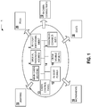
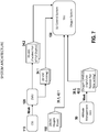
- FIG. 1 is a block diagram showing an overview of an integrated cabin system 1.
- the cabin systems comprise various elements that are able to communicate with one another over a common network 14. These elements include main cabin lighting 2, a passenger address system 4, in-flight entertainment (IFE) 6, passenger connectivity 8, crew mobile devices 10, in-seat power 12, and a control panel 13. These interact with or support a lighting system 15 that provides dynamic cabin lighting that creates an immersive experience for the passengers, monuments 16, such as galley inserts, lavatories, closets, dividers, entryways, and potable and waste water.
- the seat systems 18 integrate the IFE and passenger overhead unit (POU) power, actuation, reading lights, and controls.
- In-cabin connectivity 19 is provided for passengers, such as WiFi, Internet and IFE delivery, and entertainment content.
- the integrated cabin system includes the PSUs 20, which incorporate an attendant call, digital signage, displays, reading lights, etc.
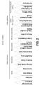
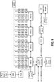
- Figure 2 provides a further breakdown of certain aircraft cabin components illustrated in Figure 1 .
- the aircraft cabin may be broken down into two primary elements: cabin interior and cabin system.
- the cabin interior which includes seats, structures, and monuments
- the seats may be broken down into first, business, and economy classes.
- the structures include PSUs, stow bins and closets, and sidewalls/flooring.
- the monuments include galley and galley inserts, lavatory lighting & waste control.
- the IFE & connectivity may be broken down into content & transactions, IFE servers and WAPs, and tables & embedded displays.
- the cabin management may include zone management, PA, and interphone, cabin and seat power, and lighting & attendant controls.
- the environmental & safety may include oxygen delivery, air conditioning & humidification, and fire suppression.
- the aircraft modification shown on the left-hand side of Figure 2 is overarching, and refers to modification of the aircraft as a whole.
- An OEM attains a type certificate (TC) from the FAA that grants regulatory authorization to fly the aircraft. All modifications done to the aircraft after original type certification are approved via amended type certificate (by the OEM) or Supplemental Type Certificate (STC) which is open for parties other than the OEM.
- TC type certificate
- STC Supplemental Type Certificate
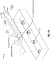
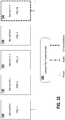
- FIG 3A illustrates an embodiment of a wiring architecture for PSUs 20 in which a group of PSUs 20 are shown. In the design shown, there are four PSUs 20 per OEU 100.
- the wiring allows cabin pressure to be monitored at each oxygen control module.
- the initiator sequencing is managed by a built-in test (BIT) power wire assert between the control modules in the column (of seats running fore and aft, and center column, on a twin aisle aircraft (left and right columns on a single aisle aircraft.
- BIT built-in test
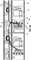
- FIG 3B is a more detailed diagram of the OEU shown in Figure 3A and illustrates the composition of the PSUs 20 and associated wiring.
- the PSUs 20 can include a programmable active display (information sign) 21 that is readily viewable by a seated passenger and displays things such as "fasten seat belt” and “no personal electronic devices (PEDs)", a dynamic seat row marker 23 that is readily viewable from a vehicle aisle, an oxygen system 24 (with masks and associated deployment hardware), a call button 26, task lights 28, and first 30 and second 32 cable bundle connectors for connecting, respectively, first 34 and second 36 cable bundles to the PSU 20. There is also a third connector 33 for connecting the oxygen system cable bundle 38 to the oxygen system 24.
- a programmable active display information sign
- PEDs personal electronic devices
- the wiring requirements include a total of forty-eight wires, broken down as follows: OEU Drops 34: an eight-wire bundle • two for power (115 VAC) • six for data (RS-485 in/out) OEU Feeds 36: a common thirty-six wire bundle • twenty for reading lights • eight for ordinance • eight for attendant call Oxygen Power 38: a four-wire bundle • main power (28VDC, 5A) • backup power (28VDC, 5A) • BIT power (28VDC, 2.5A) • common
- FIGs 4A and 4B illustrate an embodiment similar to that shown in Figures 3A and 3B , but also includes an oxygen system that has an altitude input module.
- the oxygen cable bundle 38 adds two additional wires to accommodate controller area network (CAN) (high/low) bus communications over which the altitude data can be sent and enabling health management.
- CAN controller area network
- the wiring requirements include a total of fifty wires, broken down as follows: OEU 34: Drops an eight-wire bundle • two for power (115 VAC) • six for data (RS-485 in/out) OEU Feeds 36: a common thirty-six wire bundle • twenty for reading lights • eight for ordinance • eight for attendant call Oxygen Power 38: a six -wire bundle • main power (28VDC, 5A) • backup power (28VDC, 5A) • BIT power (28VDC, 2.5A) • common • CAN (high/low)
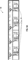
- Figures 5A and 5B illustrate a more integrated embodiment in which a single wire bundle 42 connects to the PSU 20 via a single connector 35.
- this may be a thirteen-wire bundle in which: SU Drops 34': a thirteen-wire bundle • three for 02 power (main, backup, and return) • two for 02 CAN (high/low) • two for SU power (inc. 02 BIT) • six for SU data (RS-485 in/out)
- FIG. 7 is an example block diagram layout according to an embodiment.
- the cabin services system (CSS) 110 is connected to a zone management unit (ZMU) 120 via some form of network .
- the ZMU 120 interfaces to the smart service unit (SSU) 130 providing power 34.1 (e.g., 28 VDC) and data communication 34.2 (e.g., RS-485) lines.
- Oxygen power 150 e.g., 28 VDC
- the altitude management unit 50 can be connected to the oxygen CANBUS interface via a network, and this interface is connected to the SSU 130 via cable bundle 38.2.
- Figure 8 is an example block diagram layout similar to Figure 7 , where a single cable bundle 42 is provided to the SSU 130 (the cable branching occurs at other locations within the aircraft).
- the SSU 130 reduces visual clutter for the passenger and provides a targeted delivery of information to the passenger, as is illustrated in the embodiments according to Figures G-K.
- the integrated systems permit PSU lighting scenes to be coordinated with the cabin scenes. They also permit a comprehensive onboard diagnostics and health management ability.
- the enhanced cabin crew communications provide a new tool to streamline cabin services.
- Figure 32 shows a networked interconnection between a number of service units 130 and the central service unit power/control 140 having interfaces to power, audio, and communications of the aircraft.
- Figure 9 is a block diagram illustrating an organization of the PSUs into zone management areas, each controlled by a zone management unit. It illustrates how the smart PSU elements can be integrated into an existing airplane system architecture. Everything connected with the leftmost lines on the PSU is existing. The components connected with the rightmost lines on the PSUs relate to the new "smart" PSU.
- FIG 10 is a block diagram illustrating both the PSU controller 20.1 and the oxygen controller 24.1.
- the PSU controller 20.1 contains a power supply that may take either AC (e.g., 115 VAC @ 400 Hz) or DC (e.g., 28 VDC) and convert it into DC voltage usable by the PSU controller.
- the PSU Controller contains a micro-controller with a communications interface for, e.g., RS-485 and a token-in, token-out communications. It also has I/O for the reading lights 28, attendant call, non-smoking display, fasten seatbelt display, seat row marker display, and the speaker.
- the oxygen controller 24.1 comprises a power supply converter and a micro-controller that interfaces with the oxygen system equipment 24.2.
- Figure 11 is a block diagram for the lighting controller 15.1, also including a power supply and micro-controller.
- the micro-controller interfaces to the reading lights 28.
- it shows the PSU controller interfacing to these lights.
- the lighting controller is a part of the PSU interface, and includes a zone management unit interface for RS-485 and token communications.
- Figure 10 shows the PSU controller including both lighting and oxygen system control.
- Figure 11 shows the lighting portion only, with slightly more detail.
- FIG 12 is a block diagram illustrating the oxygen controller 24.1 in a no controller area network (CAN) configuration.
- the local electronics are powered by a power supply and provide an interface to LED flow indicators and the PSU door latch that opens the door to allow oxygen masks to drop.
- the local electronics also comprise an interface to the oxygen cylinder initiator that begins the flow of high pressure oxygen into a regulator.
- the regulator controls the correct amount of oxygen flow.
- the local electronics comprise interfaces to breath sensors, control valves for the regulated oxygen, a pressure/temperature transducer, and a cabin pressure transducer.
- the breath sensor and control valve interfaces with the passenger mask to ensure proper flow of oxygen to the user.
- FIG 13 is a block diagram illustrating the oxygen controller 24.1 using a remote power distribution unit (RPDU) and CAN configuration.
- RPDU remote power distribution unit
- RDC remote data concentrator
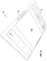
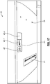
- Figure 14 is a pictorial bottom perspective view of an embodiment of a PSU 20 shown in its mounted position.
- the active display 21 shows a current seatbelt and seating status, along with a seat row marker 23 and reading/task lights 28.
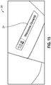
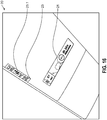
- Figure 15 is a pictorial view showing the active display 21 of the PSU 20, e.g., during a boarding phase of the flight, indicating an amount of time until departure.
- the smooth surface contour features present reduced visual clutter to the user and allow many different languages (including seat-row individualized languages) to be easily presented to passengers.
- Figure 16 shows the PSU 20 during a cruising portion of the flight, where a passenger has activated a do-not-disturb status 23.1. The remaining flight time is indicated in the active display 21, as well as a possible indication of the aircraft's position.
- Figure 17 provides an illustration in which the active display 21 provides attendant call feedback along with the particular seat it relates to, and an additional status portion 23.2 provides an illustration of a passenger preference (e.g., type of meal).
- the seat row marker 23 can light up in different colors to indicate some form of status (e.g., to help the flight attendant navigate the cabin during meal service).
- Figure 18 shows the PSU 130 during an arrival/deplaning phase, with a welcome message showing in the active display 21 and local weather information showing in the status portion 23.1 of the row marker 23.
- the PSU displays 21, 23 are connected to a centralized server unit that provides relevant status. Updates can be triggered periodically or as a result of a change of a situation, such as the passenger providing some input or some predefined point in the flight being reached.
- the PSU displays 21, 23 can be programmed to provide passengers information about the destination as well as transfer and luggage claim information and directions.
- FIG 19 is an exploded perspective view that illustrates the use of a flexible printed circuit board (flex PCB) 29 as a basis for a lighting unit containing light emitting diode (LED) lights 28.
- the flex PCB 29 is designed in a manner that keeps the components in a relatively tight packing space and on a single PCB, yet significantly thermally isolates the LEDs from the circuitry by the use of a U-shaped channel 29c that segregates the PCB 29 into an LED potion 29a, and a control circuitry portion 29b.
- the LED comprises an LED extension portion 29al that extends laterally and comprises the LED 29a2 itself.
- the control circuitry portion 29b comprises a connector that provides the PCB 29 power and control signals, and circuitry for communicating and controlling the LEDs.
- Figure 20 is an exploded side view of the LED lights 28 with flex PCB 29.
- design solutions include: variations on a traditional architecture, a centralized architecture, a centralized architecture with integrated speaker, and a centralized rib or group architecture. These architectures provides LED based lighting solutions that leverage traditional as well as modular line replaceable unit (LRU) task/reading light technologies and solutions.
- LRU modular line replaceable unit
- all of the lights may be individual LRUs and hence are vertically integrated components or they may alternatively leverage modular technology methods for all lighting applications.
- the modular approach has significant merits including enabling increased commonality of subassemblies, greater flexibility in manufacturing, easy removal/installation on the assembly line or in the field. Additionally, these lights can have all of the benefits of new LED technology including: smooth on/off transitions and optional dimming; multiple color temperatures, color rendering index (CRI) and dispersion angle options; and improved reliability and mean time between failure/mean time between unit replacement (MTBF/MTBUR).
- the variations on the traditional architecture can support an existing style OEU 100 and/or PSU 20, power and control feeds or other controllers that individually interface to each PSU/LRU. This requires a separate power run for each light, sign, marker, etc. Signals are discrete and may include some form of communications (TIA-485 or CANbus).
- the LED task/reading lights and other LEDs lights can be designed to support an 11. 4 VAC/VDC - 30 VAC/VDC input range or other input range as required.
- Each LRU may require its own power supply to interface with the power bus.
- An optional 115 VAC, 400 Hz style task/reading light can be provided and would require a separate power supply that may be incorporated in external electronics.
- Figure 21 is a bottom pictorial view illustrating placement of the various PSU 20 components, along with example dimensions for the PSU.
- the task lights 28 occupy a leftmost position
- the oxygen canister 24.2a a rightmost position.
- the oxygen masks 24.2b (above the panel) are located to the left of the oxygen canister 24.2a
- the lighted sign/display 21, speaker 27, and call light 28a are located to the left of the masks 24.2b.
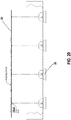
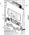
- Figure 22 is a pictorial perspective bottom view of the modified traditional embodiment in which the PSU has a generally flat bottom surface with the exception of the display 21, which may protrude from the bottom surface for easier viewing.
- This design shows the location of an oxygen mask door panel 24.3 and an oxygen canister 24.2 located at one end of the PSU 20.
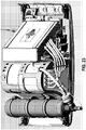
- Figure 22 is a detailed perspective top view illustrating a configuration of the various PSU components.
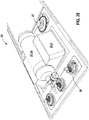
- Figure 26 illustrates a design using the centralized architecture.
- the lights for this approach leverage the same technologies deployed in the architecture discussed above while eliminating redundant power and control circuitry.
- this integrated architecture offloads all power supply functionality, control logic, and optionally oxygen system functionality onto one PC board, the power/logic module 20.1.
- This power/logic module can be centrally located in the PSU 20 or located at one side, as illustrated in Figure 26 , and allows for a single point of entry for power, control, and audio.
- the advantages for this configuration include:
- the unified and centralized architecture also enables BIT/BITE simplicity and can leverage a common microcontroller leading to a streamlined RTCA/DO-178/254 documentation process, as applicable.
- the PSU panel is designed to have a simplified modular construction that lends itself readily to kit design components and helps to reduce the part count.
- the modules may comprise a lighting module/panel portion 28 (e.g., a 2, 3, 4, or n number of lights to conform to a particular vehicle configuration), an oxygen module 24 that comprises the oxygen bottle/canister 24.2a, masks 24.2b, and related hardware, and a sign module 21 that displays signs (seatbelt, etc.) to the user.
- a lighting module/panel portion 28 e.g., a 2, 3, 4, or n number of lights to conform to a particular vehicle configuration
- an oxygen module 24 that comprises the oxygen bottle/canister 24.2a, masks 24.2b, and related hardware
- a sign module 21 that displays signs (seatbelt, etc.) to the user.
- the panel may be designed to have a smooth bottom surface when viewed from the bottom (customer view) (see Figures 14 , 17 , 18 ). In an embodiment, it has a monolithic construction or at least is manufactured to have a surface that is contiguous. In an embodiment, the contiguous surface has a large planar portion.
- the sign module portion has a translucent or semi-transparent cover (such a cover could cover the entire lower portion of the panel) so that the illuminated signs can be visible through the cover, but the cover can hide or reduce visibility of components that the customers should not see. This can be achieved by specific positioning of the lighting and other components, the use of a masked coating, which blocks the translucent cover in all areas other than the sign areas. In this way, electronics, masks, oxygen bottles, etc. are not visible to the customers during normal use.
- the PSU panel may be designed so that it utilizes a drop hinge or an articulated hinge. This permits the panel to drop away when oxygen masks need to be deployed, yet at the same time retains a clean and uncluttered appearance during normal operation of the vehicle.
- the oxygen bottle/canister 24.2a can be turned 90 degrees with respect to the other electronic components and orientation with respect to the seats (the axial direction of the cylindrical canister is perpendicular to the viewing direction of the seat locations) to make maximum use of available space.
- the axial direction is parallel to the viewing direction).
- a bottle mount 24.4 may be provided on the mask housing. This can permit a maximum storage situation when the masks are packed, while at the same time capable of being deployed.
- Figure 27 illustrates an architecture that utilizes a centralized power and control system within each SU along with a vertically integrated task/light and speaker.
- Known vehicle speakers typically are old large paper cone type speakers, which require large amplifiers. Such speakers are not tuned for optimal sound quality.
- the speaker cone is heavy and not ideal for high frequency response, which is important for intelligible audio, and such speakers take up space on the PSU 20 (where real estate is valuable).
- the speaker takes up a large volume above it (meaning other things cannot be mounted in this volume).
- New LED technology is much more efficient than traditional incandescent or fluorescent lighting. LEDs themselves, along with drive circuitry, can be shared with circuitry used to drive the speaker which frees up space in the real estate formerly occupied by both the light and the speaker.
- the speaker is vertically integrated into the reading light so that they can share a common housing.
- a speaker of this size has a higher frequency response because the cone is smaller and lighter than older traditional vehicle speaker designs. This is horn loaded and is tuned to treble, which helps with voice intelligibility, giving a nice clean sound.
- This speaker can use a small point-of-load amplifier, as opposed to a large amplifier that would be needed to drive the larger traditional speakers.
- the small amplifier can receive audio data or digital data, and in either case can be uniquely adjusted for each user. If a digital signal is used, the digital signal processing (DSP) and further processing/enhancements of the audio can be done. Such processing can include equalization and phase correction (to the extent that others' speaker outputs may be undesirably combined with the current speaker).
- DSP digital signal processing
- Such processing can include equalization and phase correction (to the extent that others' speaker outputs may be undesirably combined with the current speaker).
- the small speakers being directional means that a passenger typically will not hear their neighbor's speaker, and will not get multiple phases of their sound (delay).
- This approach would have the same features, benefits and technologies deployed in the systems described above as well as providing added value and functionality by incorporating high a quality speaker into the task/reading light assembly.
- the value this provides includes: weight savings, and space savings for other PSU and oxygen system components.
- the speaker may be located in the back of the light where the heat sink was previously located. It can pass the sound through a throat, and thus it forms a horn that directionalizes the sound.
- the reading light assembly is levitated within the throat of that horn, and the speaker sound feeds through it.
- Figure 27 illustrates an embodiment of this design, an integrated speaker/task light 200 is provided, which saves space on the PSU 20.
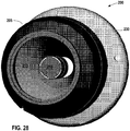
- Figure 28 is a bottom perspective view of the integrated unit 200 illustrating a housing 205 which may be of a truncated spherical form, an LED light module 210, a speaker horn 215, and a mount 230.
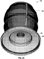
- Figure 29 is a top perspective view of the integrated unit 200 showing, in addition, the speaker 220.
- Figure 30 is a cross-sectional side view of the integrated unit 200, additionally showing the location of the speaker/light electronics 225.
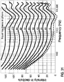
- “Horn tuning” can be used to directivity and sound pressure level (SPL) in the upper-mid to high frequency range (5k - 20k Hz) which improves intelligibility within the audible range.
- Free air architecture allows the PSU to act as an enclosure for low frequency extension. Further tuning can be accomplished via the offloaded amplifier circuit for enhancing audio perception.
- this integrated design is advantageous in that it is weight neutral with respect to existing task/reading lights, and creates an overall net weight reduction per PSU due to elimination of the PSU speaker.
- the speaker provides a superior sound quality, directivity, control, and minimization of distortion. Through the use of tunable sound filters, click/pop suppression and soft clipping can be provided in either analog or digital form.
- the speaker may not be required for all task/reading lights and/or PSU panels. In one embodiment, alternating assemblies can be utilized which may lead to further ship set weight savings.
- the vertically integrated task light and speaker may be used with any of the proposed architectures discussed above.
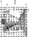
- Figure 32 illustrates a centralized rib or group architecture that utilizes a centralized power and control system outside of each SU.
- this approach leverages the same technologies and applicable features and benefits of the architectures described above. Additionally, this architecture offers even more synergy and possible part count reduction by eliminating redundant circuitry via offloading the power/logic module 140 to a separate assembly that feeds a group of PSU's 130. Costs can be potentially lowered by a reduction in overall 115 VAC, 400 Hz shipside power supply count/capacity that typically require a larger front end for power factor correction and harmonic distortion reduction. This has traditionally been a major cost/weight driver for individual power supplies.
- the architecture is scalable and may be integrated into existing aircraft subsystems.
- the lighting elements may be individual LRUs and are either vertically integrated LED based components or are LED driven fiber optic end nodes that can also be designed in a modular fashion thus enabling increased commonality and flexibility.
- fiber optic/light pipes and associated driver engines can be utilized to transmit light to task/reading, ordinance, call lights, etc. This offloads all LED's and their associated electronics/heat sources to a single LRU.
- This multiplexed light engine could have its own passive thermal management and power supply with multiple collimated fiber outputs that can have a range of several feet. Reliability is enhanced by virtue of commonality and reduced part numbers/count. Power and control to this LRU is a single feed for multiple SU's. Communications may be daisy chained via a TIA-485 architecture or a similar multi-drop topology.
Landscapes
- Engineering & Computer Science (AREA)
- Multimedia (AREA)
- Aviation & Aerospace Engineering (AREA)
- Physics & Mathematics (AREA)
- Acoustics & Sound (AREA)
- Signal Processing (AREA)
- General Engineering & Computer Science (AREA)
- Health & Medical Sciences (AREA)
- Otolaryngology (AREA)
- Circuit Arrangement For Electric Light Sources In General (AREA)
- Non-Portable Lighting Devices Or Systems Thereof (AREA)
Claims (10)
- Passagierserviceeinheit (20) für eine Flugzeugkabine, umfassend:einen Befestigungsmechanismus zum Befestigen der Passagierserviceeinheit (20) über mindestens einem Sitz;eine dynamische Sitzreihenmarkierung (23), die dazu eingerichtet ist, eine Sitzposition anzuzeigen, und einen Statusabschnitt, der einen Passagierstatus oder einen Reiseaspekt anzeigt, der von einem Flugzeuggang aus leicht sichtbar ist und während einer Reise änderbar ist;ein programmierbares aktives Display, das vom Sitz aus leicht sichtbar ist und dem Passagier entsprechend der Reise änderbare Informationen über die Reise bereitstellt;ein Sauerstoffversorgungsmodul (24), umfassend einen Sauerstoffkanister (24.2a) und eine Mehrzahl von Sauerstoffmasken (24.2b);ein Beleuchtungsmodul (28), das eine Mehrzahl von LED-Leseleuchten umfasst;mindestens einen Lautsprecher (220) umfassend einen Schalltrichter (215), das einen kreisförmigem Querschnitt aufweist; undein Stromversorgungs-/Logikmodul (20.1) zum Steuern des Beleuchtungsmoduls (28) und des mindestens einen Lautsprechers (220), wobei das Stromversorgungs-/Logikmodul (20.1) umfasst:eine Stromversorgung, die dazu angepasst ist, den zugeführten Wechsel- oder Gleichstrom in Gleichspannung umzuwandeln, die von dem Stromversorgungs-/Logikmodul (20.1) verwendet werden kann, undeine gemeinsame Datenkommunikationsschnittstelle zur Kommunikation mit einem Kabinenmanagementsystem; undwobei ein erster Lautsprecher (200) von dem mindestens einen Lautsprecher (200) vertikal in eine erste LED-Leseleuchte der Mehrzahl von LED-Leseleuchten integriert ist, wobei eine LED zum Beleuchten der ersten LED-Leseleuchte zumindest teilweise von dem Schalltrichter (215) des ersten Lautsprechers umgeben ist, und wobei sich der erste Lautsprecher (200) und die erste LED-Leseleuchte ein gemeinsames Gehäuse teilen.
- Passagierserviceeinheit nach Anspruch 1, umfassend eine flexible Leiterplatte (29), die einen Steuerschaltungsabschnitt (29b) und einen LED-Abschnitt (29a) aufweist, der eine Mehrzahl von LEDs zum Beleuchten der Mehrzahl von LED-Leseleuchten enthält.
- Passagierserviceeinheit nach Anspruch 1, wobei der mindestens eine Lautsprecher drei Lautsprecher umfasst, die jeweils in eine jeweilige LED-Leseleuchte der Mehrzahl von Leseleuchten integriert sind.
- Passagierserviceeinheit nach Anspruch 1, wobei der erste Lautsprecher auf einen Passagier gerichtet ist, der positioniert ist, um die erste LED-Leseleuchte verwenden zu können.
- Passagierserviceeinheit nach Anspruch 1, wobei die dynamische Sitzreihenmarkierung (23) ausgelegt ist, um eine Mahlzeitpräferenz eines Passagiers auszuweisen, der unter der Passagierserviceeinheit sitzt.
- Passagierserviceeinheit nach Anspruch 1, wobei das programmierbare aktive Display ausgelegt ist, um Gepäckausgabeinformationen anzuzeigen.
- Passagierserviceeinheit nach irgendeinem der Ansprüche 1 bis 6, wobei der Sauerstoffkanister (24.2a) des Sauerstoffversorgungsmoduls (24) senkrecht zu einer Längsachse der Passagierserviceeinheit (20) befestigt ist.
- Passagierserviceeinheit nach irgendeinem der Ansprüche 1 bis 7, weiterhin umfassend eine durchscheinende Abdeckung, die über dem Schildermodul (21) angeordnet ist.
- Passagierserviceeinheit nach Anspruch 8, wobei die durchscheinende Abdeckung ein Abschnitt einer Abdeckung ist, die über einen gesamten unteren Abschnitt der Passagierserviceeinheit angeordnet ist.
- Passagierserviceeinheit nach Anspruch 1, weiterhin umfassend einen einzelnen Konnektor (35) für ein einzelnes Leitungsbündel (42), der von einer externen Quelle in die Passagierserviceeinheit eintritt, wobei das einzelne Leitungsbündel (42) die gemeinsame Datenkommunikationsschnittstelle und eine Stromversorgung für die Passagierserviceeinheit umfasst.
Applications Claiming Priority (4)
| Application Number | Priority Date | Filing Date | Title |
|---|---|---|---|
| US201462057133P | 2014-09-29 | 2014-09-29 | |
| US201562133123P | 2015-03-13 | 2015-03-13 | |
| US201562173855P | 2015-06-10 | 2015-06-10 | |
| PCT/US2015/053022 WO2016054097A1 (en) | 2014-09-29 | 2015-09-29 | Smart passenger service unit |
Publications (3)
| Publication Number | Publication Date |
|---|---|
| EP3201089A1 EP3201089A1 (de) | 2017-08-09 |
| EP3201089A4 EP3201089A4 (de) | 2018-09-05 |
| EP3201089B1 true EP3201089B1 (de) | 2021-04-07 |
Family
ID=55583669
Family Applications (1)
| Application Number | Title | Priority Date | Filing Date |
|---|---|---|---|
| EP15846009.7A Active EP3201089B1 (de) | 2014-09-29 | 2015-09-29 | Intelligente fahrgastserviceeinheit |
Country Status (4)
| Country | Link |
|---|---|
| US (1) | US10219059B2 (de) |
| EP (1) | EP3201089B1 (de) |
| CN (1) | CN107108034B (de) |
| WO (1) | WO2016054097A1 (de) |
Families Citing this family (23)
| Publication number | Priority date | Publication date | Assignee | Title |
|---|---|---|---|---|
| WO2016054097A1 (en) * | 2014-09-29 | 2016-04-07 | B/E Aerospace, Inc. | Smart passenger service unit |
| US9742898B2 (en) * | 2015-08-31 | 2017-08-22 | The Boeing Company | Mobile cabin panel |
| US10239617B2 (en) * | 2015-09-11 | 2019-03-26 | The Boeing Company | Oxygen box for a limited maintenance access area above a ceiling panel of an aircraft cabin |
| US10097950B2 (en) * | 2015-11-06 | 2018-10-09 | Systems And Software Enterprises, Llc | Method of associating locations with devices |
| WO2017087566A1 (en) * | 2015-11-16 | 2017-05-26 | Civiq Smartscapes, Llc | Techniques and systems for servicing a personal communication structure (pcs) |
| US10214287B2 (en) * | 2016-02-26 | 2019-02-26 | The Boeing Company | Vehicle cabin wayfinding assembly |
| EP3235545B1 (de) * | 2016-04-22 | 2018-10-03 | Airbus Operations GmbH | Sauerstoffversorgungsanlage mit integrierter testausrüstung |
| US10200110B2 (en) * | 2016-06-30 | 2019-02-05 | Ge Aviation Systems Llc | Aviation protocol conversion |
| US10513335B2 (en) * | 2016-10-07 | 2019-12-24 | The Boeing Company | Systems and methods for providing electrical signals to electrical devices within an interior cabin of a vehicle |
| US10118701B2 (en) * | 2017-03-08 | 2018-11-06 | B/E Aerospace, Inc. | Aircraft cabin LED lighting system and lighting assembly |
| US10800543B2 (en) * | 2017-03-30 | 2020-10-13 | Safran Seats Usa Llc | Passenger communication system |
| CN107270213A (zh) * | 2017-05-05 | 2017-10-20 | 中国商用飞机有限责任公司 | 一种内饰集成式应急照明装置 |
| DE102017009880B4 (de) * | 2017-10-24 | 2023-03-02 | Diehl Aerospace Gmbh | Adresszuteilung an PSUs, Serviceanordnung und Passagierkabine |
| GB2595198B (en) | 2018-02-07 | 2023-06-14 | Ifpl Group Ltd | Apparatus for device charging |
| US10906646B2 (en) * | 2018-05-11 | 2021-02-02 | B/E Aerospace, Inc. | Integrated passenger service unit (PSU) |
| WO2020024335A1 (zh) * | 2018-08-03 | 2020-02-06 | 李宗谕 | 民用飞机客舱内供电方法 |
| US20200164233A1 (en) * | 2018-11-28 | 2020-05-28 | Zodiac Cabin Controls Gmbh | Oxygen system with electronic flow indication |
| CN110636060B (zh) * | 2019-09-19 | 2021-03-23 | 西北工业大学 | 一种民用飞机可靠实时无线语音传输方法 |
| US11615542B2 (en) * | 2019-11-14 | 2023-03-28 | Panasonic Avionics Corporation | Automatic perspective correction for in-flight entertainment (IFE) monitors |
| CN111049549A (zh) * | 2019-11-28 | 2020-04-21 | 太仓市同维电子有限公司 | 一种具有bite功能的民用机载wifi系统 |
| US11655032B2 (en) * | 2020-03-19 | 2023-05-23 | B/E Aerospace, Inc. | Systems and methods for efficient boarding of passenger vehicles |
| US11490484B1 (en) | 2021-10-15 | 2022-11-01 | Aircraft Lighting International Inc. | Retrofit light-emitting diode lamp and circuit thereof |
| EP4414265A1 (de) * | 2023-02-08 | 2024-08-14 | B/E Aerospace, Inc. | Exekutiver und in vip-sitz integrierter luftionisator |
Citations (2)
| Publication number | Priority date | Publication date | Assignee | Title |
|---|---|---|---|---|
| US20080298045A1 (en) * | 2005-06-17 | 2008-12-04 | Doug Wright | Recessed light fixture and speaker combination |
| US20160090192A1 (en) * | 2014-09-29 | 2016-03-31 | B/E Aerospace, Inc. | Smart passenger service unit |
Family Cites Families (26)
| Publication number | Priority date | Publication date | Assignee | Title |
|---|---|---|---|---|
| US4158400A (en) | 1978-05-15 | 1979-06-19 | Vice Charles L | Sound reproducing system |
| US6393343B1 (en) * | 1997-03-13 | 2002-05-21 | Airbus Deutschland Gmbh | Passenger service unit and an aircraft cabin systems control with such service units |
| US5980057A (en) * | 1997-11-10 | 1999-11-09 | Recoton Corporation | Speaker light unit connected to conventional electrical light socket |
| US6371637B1 (en) | 1999-02-26 | 2002-04-16 | Radiantz, Inc. | Compact, flexible, LED array |
| US6177887B1 (en) * | 1999-07-06 | 2001-01-23 | George A. Jerome | Multi-passenger vehicle catering and entertainment system |
| DE60330153D1 (de) | 2002-07-16 | 2009-12-31 | Odelo Gmbh | Weiss-led-scheinwerfer |
| KR100576866B1 (ko) | 2004-06-16 | 2006-05-10 | 삼성전기주식회사 | 발광다이오드 및 그 제조방법 |
| US6998538B1 (en) * | 2004-07-30 | 2006-02-14 | Ulectra Corporation | Integrated power and data insulated electrical cable having a metallic outer jacket |
| US7692099B2 (en) | 2005-09-19 | 2010-04-06 | Telefonix, Inc. | Flexible and lightweight seat-to-seat cabin cable system and method of manufacturing same |
| US20070107277A1 (en) * | 2005-11-14 | 2007-05-17 | The Boeing Company | Seat identification system |
| DE102007052671B4 (de) * | 2007-11-05 | 2012-11-08 | Airbus Operations Gmbh | Anzeigemodul zum Anzeigen von passagierspezifischen Anzeigeinformationen |
| US8240875B2 (en) | 2008-06-25 | 2012-08-14 | Cree, Inc. | Solid state linear array modules for general illumination |
| US20160053977A1 (en) | 2008-09-24 | 2016-02-25 | B/E Aerospace, Inc. | Flexible led lighting element |
| US20100188778A1 (en) | 2009-01-29 | 2010-07-29 | Castagna Joseph T | Disk Drive Assembly Having Flexible Support for Flexible Printed Circuit Board |
| US8300869B2 (en) * | 2009-04-02 | 2012-10-30 | Mitek Corp., Inc. | Lighting and audio communication system |
| WO2011082998A1 (de) * | 2009-12-15 | 2011-07-14 | Airbus Operations Gmbh | Versorgungsmodul für personentransportfahrzeuge |
| KR101671389B1 (ko) * | 2010-03-05 | 2016-11-01 | 삼성전자 주식회사 | 가변 대역 폭 적응 노치 필터, 및 가변 대역 폭 적응 노치 필터를 이용하여 하울링을 제거하는 방법 및 장치 |
| DE102010018502A1 (de) | 2010-04-28 | 2011-11-03 | Airbus Operations Gmbh | Versorgungssystem zur Versorgung von Passagieren in einem Passagierraum eines Fahrzeugs |
| DE102011013368B4 (de) * | 2011-03-08 | 2024-02-01 | Diehl Aerospace Gmbh | Passagier-Serviceeinheit, Passagier-Servicekanal sowie Verkehrsmittel |
| US20120307487A1 (en) * | 2011-06-01 | 2012-12-06 | B/E Aerospace, Inc. | Vehicle LED Reading Light Grouping System and Method |
| US9756733B2 (en) | 2011-10-04 | 2017-09-05 | Apple Inc. | Display and multi-layer printed circuit board with shared flexible substrate |
| US9079528B2 (en) * | 2012-02-14 | 2015-07-14 | C&D Zodiac, Inc. | PSU pod assembly and method for using same |
| US20130340749A1 (en) * | 2012-06-22 | 2013-12-26 | Wolfgang Rittner | Passenger reading light integrated in psu/emergency oxygen device |
| US8806543B1 (en) * | 2013-03-05 | 2014-08-12 | The Boeing Company | In-flight passenger information system |
| US9335034B2 (en) | 2013-09-27 | 2016-05-10 | Osram Sylvania Inc | Flexible circuit board for electronic applications, light source containing same, and method of making |
| US9487296B2 (en) * | 2013-09-30 | 2016-11-08 | Peco Manufacturing Co., Inc. | Passenger service unit and related systems |
-
2015
- 2015-09-29 WO PCT/US2015/053022 patent/WO2016054097A1/en not_active Ceased
- 2015-09-29 CN CN201580059348.0A patent/CN107108034B/zh active Active
- 2015-09-29 EP EP15846009.7A patent/EP3201089B1/de active Active
- 2015-09-29 US US14/869,651 patent/US10219059B2/en active Active
Patent Citations (2)
| Publication number | Priority date | Publication date | Assignee | Title |
|---|---|---|---|---|
| US20080298045A1 (en) * | 2005-06-17 | 2008-12-04 | Doug Wright | Recessed light fixture and speaker combination |
| US20160090192A1 (en) * | 2014-09-29 | 2016-03-31 | B/E Aerospace, Inc. | Smart passenger service unit |
Also Published As
| Publication number | Publication date |
|---|---|
| EP3201089A1 (de) | 2017-08-09 |
| CN107108034A (zh) | 2017-08-29 |
| WO2016054097A1 (en) | 2016-04-07 |
| EP3201089A4 (de) | 2018-09-05 |
| US10219059B2 (en) | 2019-02-26 |
| US20160090192A1 (en) | 2016-03-31 |
| CN107108034B (zh) | 2021-03-09 |
Similar Documents
| Publication | Publication Date | Title |
|---|---|---|
| EP3201089B1 (de) | Intelligente fahrgastserviceeinheit | |
| US10715911B2 (en) | Smart passenger service unit | |
| US7036889B2 (en) | Aircraft passenger seat and in-flight entertainment integrated electronics | |
| US9499270B2 (en) | Supply module for passenger transport vehicles | |
| CN102770346B (zh) | 用于在座椅处提供集成用户接口系统的系统和方法 | |
| US8128027B2 (en) | Plug-n-play power system for an accessory in an aircraft | |
| US6824104B2 (en) | Under floor remote seat cluster and integrated housing system for aircraft passenger entertainment systems and the like | |
| US20070057121A1 (en) | Simplified power system for a cabin services system for an aircraft | |
| US20120191297A1 (en) | Simplified cabin services system for an aircraft | |
| US8485703B2 (en) | Aircraft cabin lighting system and kit therefor | |
| US20080104642A1 (en) | Cabin management and entertainment system | |
| US20120230530A1 (en) | Passenger service unit, passenger service channel and means of transport | |
| ATE259075T1 (de) | Datenverwaltungssystem fuer ein flugzeug | |
| JP2005531267A (ja) | 航空機通信配信システム | |
| US10644785B2 (en) | Wireless distribution of aircraft data and/or avionics parameters and/or control commands between a standardized aircraft interface point and other systems, e.g., passenger entertainment systems | |
| US11203441B2 (en) | Monitoring system for the cabin of an aircraft, data distribution apparatus and aircraft | |
| US12528598B2 (en) | Programmable lighting methods and systems for a removable peripheral bar | |
| EP3241748B1 (de) | Sitzmodul mit einem drahtloskommunikationsmodul, fahrzeugsitz mit sitzmodul, flugzeug und verfahren zum betätigen eines sitzmoduls | |
| US9481463B2 (en) | Panel and system for aircraft cabin management | |
| US9359083B2 (en) | Rotorcraft fitted with a mounting structure for jointly mounting a control panel and avionics rack previously fitted with a unitary cabling assembly | |
| US7971221B2 (en) | Overhead video system for an aircraft | |
| JP2011041257A (ja) | 客室制御システム検証方法 | |
| RU2473117C2 (ru) | Интеллектуальная информационная система для пассажирского салона самолета | |
| FR2887051A1 (fr) | Systeme de commande et d'alimentation electrique pour sieges d'avion |
Legal Events
| Date | Code | Title | Description |
|---|---|---|---|
| STAA | Information on the status of an ep patent application or granted ep patent |
Free format text: STATUS: THE INTERNATIONAL PUBLICATION HAS BEEN MADE |
|
| PUAI | Public reference made under article 153(3) epc to a published international application that has entered the european phase |
Free format text: ORIGINAL CODE: 0009012 |
|
| STAA | Information on the status of an ep patent application or granted ep patent |
Free format text: STATUS: REQUEST FOR EXAMINATION WAS MADE |
|
| 17P | Request for examination filed |
Effective date: 20170427 |
|
| AK | Designated contracting states |
Kind code of ref document: A1 Designated state(s): AL AT BE BG CH CY CZ DE DK EE ES FI FR GB GR HR HU IE IS IT LI LT LU LV MC MK MT NL NO PL PT RO RS SE SI SK SM TR |
|
| AX | Request for extension of the european patent |
Extension state: BA ME |
|
| DAV | Request for validation of the european patent (deleted) | ||
| DAX | Request for extension of the european patent (deleted) | ||
| RIN1 | Information on inventor provided before grant (corrected) |
Inventor name: TODZIA, JONATHAN Inventor name: JOHANNESSEN, ERIC Inventor name: LASALA, DONALD Inventor name: BARKER, JOHN TERENCE Inventor name: LINTON, ROBERT Inventor name: MOSS, RONNIE R. Inventor name: DUNN, MATTHEW Inventor name: GAMBESKI, GANNON T. Inventor name: SAM, LUIS Inventor name: PECK, JESSE RICHARD |
|
| A4 | Supplementary search report drawn up and despatched |
Effective date: 20180808 |
|
| RIC1 | Information provided on ipc code assigned before grant |
Ipc: B64D 11/00 20060101AFI20180802BHEP Ipc: F21V 33/00 20060101ALI20180802BHEP |
|
| STAA | Information on the status of an ep patent application or granted ep patent |
Free format text: STATUS: EXAMINATION IS IN PROGRESS |
|
| 17Q | First examination report despatched |
Effective date: 20180917 |
|
| RIC1 | Information provided on ipc code assigned before grant |
Ipc: B64D 11/00 20060101AFI20180912BHEP Ipc: F21V 33/00 20060101ALI20180912BHEP |
|
| GRAP | Despatch of communication of intention to grant a patent |
Free format text: ORIGINAL CODE: EPIDOSNIGR1 |
|
| STAA | Information on the status of an ep patent application or granted ep patent |
Free format text: STATUS: GRANT OF PATENT IS INTENDED |
|
| INTG | Intention to grant announced |
Effective date: 20201022 |
|
| GRAS | Grant fee paid |
Free format text: ORIGINAL CODE: EPIDOSNIGR3 |
|
| GRAA | (expected) grant |
Free format text: ORIGINAL CODE: 0009210 |
|
| STAA | Information on the status of an ep patent application or granted ep patent |
Free format text: STATUS: THE PATENT HAS BEEN GRANTED |
|
| AK | Designated contracting states |
Kind code of ref document: B1 Designated state(s): AL AT BE BG CH CY CZ DE DK EE ES FI FR GB GR HR HU IE IS IT LI LT LU LV MC MK MT NL NO PL PT RO RS SE SI SK SM TR |
|
| REG | Reference to a national code |
Ref country code: GB Ref legal event code: FG4D |
|
| REG | Reference to a national code |
Ref country code: AT Ref legal event code: REF Ref document number: 1379386 Country of ref document: AT Kind code of ref document: T Effective date: 20210415 Ref country code: CH Ref legal event code: EP |
|
| REG | Reference to a national code |
Ref country code: DE Ref legal event code: R096 Ref document number: 602015067901 Country of ref document: DE |
|
| REG | Reference to a national code |
Ref country code: IE Ref legal event code: FG4D |
|
| REG | Reference to a national code |
Ref country code: LT Ref legal event code: MG9D |
|
| REG | Reference to a national code |
Ref country code: NL Ref legal event code: MP Effective date: 20210407 Ref country code: AT Ref legal event code: MK05 Ref document number: 1379386 Country of ref document: AT Kind code of ref document: T Effective date: 20210407 |
|
| PG25 | Lapsed in a contracting state [announced via postgrant information from national office to epo] |
Ref country code: FI Free format text: LAPSE BECAUSE OF FAILURE TO SUBMIT A TRANSLATION OF THE DESCRIPTION OR TO PAY THE FEE WITHIN THE PRESCRIBED TIME-LIMIT Effective date: 20210407 Ref country code: NL Free format text: LAPSE BECAUSE OF FAILURE TO SUBMIT A TRANSLATION OF THE DESCRIPTION OR TO PAY THE FEE WITHIN THE PRESCRIBED TIME-LIMIT Effective date: 20210407 Ref country code: LT Free format text: LAPSE BECAUSE OF FAILURE TO SUBMIT A TRANSLATION OF THE DESCRIPTION OR TO PAY THE FEE WITHIN THE PRESCRIBED TIME-LIMIT Effective date: 20210407 Ref country code: BG Free format text: LAPSE BECAUSE OF FAILURE TO SUBMIT A TRANSLATION OF THE DESCRIPTION OR TO PAY THE FEE WITHIN THE PRESCRIBED TIME-LIMIT Effective date: 20210707 Ref country code: AT Free format text: LAPSE BECAUSE OF FAILURE TO SUBMIT A TRANSLATION OF THE DESCRIPTION OR TO PAY THE FEE WITHIN THE PRESCRIBED TIME-LIMIT Effective date: 20210407 Ref country code: HR Free format text: LAPSE BECAUSE OF FAILURE TO SUBMIT A TRANSLATION OF THE DESCRIPTION OR TO PAY THE FEE WITHIN THE PRESCRIBED TIME-LIMIT Effective date: 20210407 |
|
| PG25 | Lapsed in a contracting state [announced via postgrant information from national office to epo] |
Ref country code: IS Free format text: LAPSE BECAUSE OF FAILURE TO SUBMIT A TRANSLATION OF THE DESCRIPTION OR TO PAY THE FEE WITHIN THE PRESCRIBED TIME-LIMIT Effective date: 20210807 Ref country code: LV Free format text: LAPSE BECAUSE OF FAILURE TO SUBMIT A TRANSLATION OF THE DESCRIPTION OR TO PAY THE FEE WITHIN THE PRESCRIBED TIME-LIMIT Effective date: 20210407 Ref country code: GR Free format text: LAPSE BECAUSE OF FAILURE TO SUBMIT A TRANSLATION OF THE DESCRIPTION OR TO PAY THE FEE WITHIN THE PRESCRIBED TIME-LIMIT Effective date: 20210708 Ref country code: NO Free format text: LAPSE BECAUSE OF FAILURE TO SUBMIT A TRANSLATION OF THE DESCRIPTION OR TO PAY THE FEE WITHIN THE PRESCRIBED TIME-LIMIT Effective date: 20210707 Ref country code: PT Free format text: LAPSE BECAUSE OF FAILURE TO SUBMIT A TRANSLATION OF THE DESCRIPTION OR TO PAY THE FEE WITHIN THE PRESCRIBED TIME-LIMIT Effective date: 20210809 Ref country code: PL Free format text: LAPSE BECAUSE OF FAILURE TO SUBMIT A TRANSLATION OF THE DESCRIPTION OR TO PAY THE FEE WITHIN THE PRESCRIBED TIME-LIMIT Effective date: 20210407 Ref country code: SE Free format text: LAPSE BECAUSE OF FAILURE TO SUBMIT A TRANSLATION OF THE DESCRIPTION OR TO PAY THE FEE WITHIN THE PRESCRIBED TIME-LIMIT Effective date: 20210407 Ref country code: RS Free format text: LAPSE BECAUSE OF FAILURE TO SUBMIT A TRANSLATION OF THE DESCRIPTION OR TO PAY THE FEE WITHIN THE PRESCRIBED TIME-LIMIT Effective date: 20210407 |
|
| REG | Reference to a national code |
Ref country code: DE Ref legal event code: R097 Ref document number: 602015067901 Country of ref document: DE |
|
| PG25 | Lapsed in a contracting state [announced via postgrant information from national office to epo] |
Ref country code: SK Free format text: LAPSE BECAUSE OF FAILURE TO SUBMIT A TRANSLATION OF THE DESCRIPTION OR TO PAY THE FEE WITHIN THE PRESCRIBED TIME-LIMIT Effective date: 20210407 Ref country code: SM Free format text: LAPSE BECAUSE OF FAILURE TO SUBMIT A TRANSLATION OF THE DESCRIPTION OR TO PAY THE FEE WITHIN THE PRESCRIBED TIME-LIMIT Effective date: 20210407 Ref country code: DK Free format text: LAPSE BECAUSE OF FAILURE TO SUBMIT A TRANSLATION OF THE DESCRIPTION OR TO PAY THE FEE WITHIN THE PRESCRIBED TIME-LIMIT Effective date: 20210407 Ref country code: CZ Free format text: LAPSE BECAUSE OF FAILURE TO SUBMIT A TRANSLATION OF THE DESCRIPTION OR TO PAY THE FEE WITHIN THE PRESCRIBED TIME-LIMIT Effective date: 20210407 Ref country code: EE Free format text: LAPSE BECAUSE OF FAILURE TO SUBMIT A TRANSLATION OF THE DESCRIPTION OR TO PAY THE FEE WITHIN THE PRESCRIBED TIME-LIMIT Effective date: 20210407 Ref country code: ES Free format text: LAPSE BECAUSE OF FAILURE TO SUBMIT A TRANSLATION OF THE DESCRIPTION OR TO PAY THE FEE WITHIN THE PRESCRIBED TIME-LIMIT Effective date: 20210407 Ref country code: RO Free format text: LAPSE BECAUSE OF FAILURE TO SUBMIT A TRANSLATION OF THE DESCRIPTION OR TO PAY THE FEE WITHIN THE PRESCRIBED TIME-LIMIT Effective date: 20210407 |
|
| PLBE | No opposition filed within time limit |
Free format text: ORIGINAL CODE: 0009261 |
|
| STAA | Information on the status of an ep patent application or granted ep patent |
Free format text: STATUS: NO OPPOSITION FILED WITHIN TIME LIMIT |
|
| 26N | No opposition filed |
Effective date: 20220110 |
|
| REG | Reference to a national code |
Ref country code: CH Ref legal event code: PL |
|
| REG | Reference to a national code |
Ref country code: BE Ref legal event code: MM Effective date: 20210930 |
|
| PG25 | Lapsed in a contracting state [announced via postgrant information from national office to epo] |
Ref country code: IS Free format text: LAPSE BECAUSE OF FAILURE TO SUBMIT A TRANSLATION OF THE DESCRIPTION OR TO PAY THE FEE WITHIN THE PRESCRIBED TIME-LIMIT Effective date: 20210807 Ref country code: MC Free format text: LAPSE BECAUSE OF FAILURE TO SUBMIT A TRANSLATION OF THE DESCRIPTION OR TO PAY THE FEE WITHIN THE PRESCRIBED TIME-LIMIT Effective date: 20210407 Ref country code: AL Free format text: LAPSE BECAUSE OF FAILURE TO SUBMIT A TRANSLATION OF THE DESCRIPTION OR TO PAY THE FEE WITHIN THE PRESCRIBED TIME-LIMIT Effective date: 20210407 |
|
| PG25 | Lapsed in a contracting state [announced via postgrant information from national office to epo] |
Ref country code: LU Free format text: LAPSE BECAUSE OF NON-PAYMENT OF DUE FEES Effective date: 20210929 Ref country code: IT Free format text: LAPSE BECAUSE OF FAILURE TO SUBMIT A TRANSLATION OF THE DESCRIPTION OR TO PAY THE FEE WITHIN THE PRESCRIBED TIME-LIMIT Effective date: 20210407 Ref country code: IE Free format text: LAPSE BECAUSE OF NON-PAYMENT OF DUE FEES Effective date: 20210929 Ref country code: BE Free format text: LAPSE BECAUSE OF NON-PAYMENT OF DUE FEES Effective date: 20210930 |
|
| PG25 | Lapsed in a contracting state [announced via postgrant information from national office to epo] |
Ref country code: LI Free format text: LAPSE BECAUSE OF NON-PAYMENT OF DUE FEES Effective date: 20210930 Ref country code: CH Free format text: LAPSE BECAUSE OF NON-PAYMENT OF DUE FEES Effective date: 20210930 |
|
| PG25 | Lapsed in a contracting state [announced via postgrant information from national office to epo] |
Ref country code: HU Free format text: LAPSE BECAUSE OF FAILURE TO SUBMIT A TRANSLATION OF THE DESCRIPTION OR TO PAY THE FEE WITHIN THE PRESCRIBED TIME-LIMIT; INVALID AB INITIO Effective date: 20150929 |
|
| PG25 | Lapsed in a contracting state [announced via postgrant information from national office to epo] |
Ref country code: CY Free format text: LAPSE BECAUSE OF FAILURE TO SUBMIT A TRANSLATION OF THE DESCRIPTION OR TO PAY THE FEE WITHIN THE PRESCRIBED TIME-LIMIT Effective date: 20210407 |
|
| PG25 | Lapsed in a contracting state [announced via postgrant information from national office to epo] |
Ref country code: MK Free format text: LAPSE BECAUSE OF FAILURE TO SUBMIT A TRANSLATION OF THE DESCRIPTION OR TO PAY THE FEE WITHIN THE PRESCRIBED TIME-LIMIT Effective date: 20210407 |
|
| PG25 | Lapsed in a contracting state [announced via postgrant information from national office to epo] |
Ref country code: TR Free format text: LAPSE BECAUSE OF FAILURE TO SUBMIT A TRANSLATION OF THE DESCRIPTION OR TO PAY THE FEE WITHIN THE PRESCRIBED TIME-LIMIT Effective date: 20210407 |
|
| PG25 | Lapsed in a contracting state [announced via postgrant information from national office to epo] |
Ref country code: MT Free format text: LAPSE BECAUSE OF FAILURE TO SUBMIT A TRANSLATION OF THE DESCRIPTION OR TO PAY THE FEE WITHIN THE PRESCRIBED TIME-LIMIT Effective date: 20210407 |
|
| PGFP | Annual fee paid to national office [announced via postgrant information from national office to epo] |
Ref country code: DE Payment date: 20250820 Year of fee payment: 11 |
|
| PGFP | Annual fee paid to national office [announced via postgrant information from national office to epo] |
Ref country code: GB Payment date: 20250822 Year of fee payment: 11 |
|
| PGFP | Annual fee paid to national office [announced via postgrant information from national office to epo] |
Ref country code: FR Payment date: 20250820 Year of fee payment: 11 |
|
| P01 | Opt-out of the competence of the unified patent court (upc) registered |
Free format text: CASE NUMBER: UPC_APP_0016897_3201089/2025 Effective date: 20251210 |