EP3201436B1 - Appareil et procédé d'obtention d'un échantillon fluidique dans un puits - Google Patents
Appareil et procédé d'obtention d'un échantillon fluidique dans un puits Download PDFInfo
- Publication number
- EP3201436B1 EP3201436B1 EP15846896.7A EP15846896A EP3201436B1 EP 3201436 B1 EP3201436 B1 EP 3201436B1 EP 15846896 A EP15846896 A EP 15846896A EP 3201436 B1 EP3201436 B1 EP 3201436B1
- Authority
- EP
- European Patent Office
- Prior art keywords
- piston
- chamber
- fluid
- well
- cylinder
- Prior art date
- Legal status (The legal status is an assumption and is not a legal conclusion. Google has not performed a legal analysis and makes no representation as to the accuracy of the status listed.)
- Active
Links
Images



Classifications
-
- E—FIXED CONSTRUCTIONS
- E21—EARTH OR ROCK DRILLING; MINING
- E21B—EARTH OR ROCK DRILLING; OBTAINING OIL, GAS, WATER, SOLUBLE OR MELTABLE MATERIALS OR A SLURRY OF MINERALS FROM WELLS
- E21B49/00—Testing the nature of borehole walls; Formation testing; Methods or apparatus for obtaining samples of soil or well fluids, specially adapted to earth drilling or wells
- E21B49/08—Obtaining fluid samples or testing fluids, in boreholes or wells
- E21B49/081—Obtaining fluid samples or testing fluids, in boreholes or wells with down-hole means for trapping a fluid sample
- E21B49/0815—Sampling valve actuated by tubing pressure changes
-
- E—FIXED CONSTRUCTIONS
- E21—EARTH OR ROCK DRILLING; MINING
- E21B—EARTH OR ROCK DRILLING; OBTAINING OIL, GAS, WATER, SOLUBLE OR MELTABLE MATERIALS OR A SLURRY OF MINERALS FROM WELLS
- E21B49/00—Testing the nature of borehole walls; Formation testing; Methods or apparatus for obtaining samples of soil or well fluids, specially adapted to earth drilling or wells
- E21B49/08—Obtaining fluid samples or testing fluids, in boreholes or wells
-
- G—PHYSICS
- G01—MEASURING; TESTING
- G01N—INVESTIGATING OR ANALYSING MATERIALS BY DETERMINING THEIR CHEMICAL OR PHYSICAL PROPERTIES
- G01N1/00—Sampling; Preparing specimens for investigation
- G01N1/02—Devices for withdrawing samples
- G01N1/10—Devices for withdrawing samples in the liquid or fluent state
-
- G—PHYSICS
- G01—MEASURING; TESTING
- G01N—INVESTIGATING OR ANALYSING MATERIALS BY DETERMINING THEIR CHEMICAL OR PHYSICAL PROPERTIES
- G01N1/00—Sampling; Preparing specimens for investigation
- G01N1/02—Devices for withdrawing samples
- G01N1/10—Devices for withdrawing samples in the liquid or fluent state
- G01N1/20—Devices for withdrawing samples in the liquid or fluent state for flowing or falling materials
- G01N1/2035—Devices for withdrawing samples in the liquid or fluent state for flowing or falling materials by deviating part of a fluid stream, e.g. by drawing-off or tapping
-
- G—PHYSICS
- G01—MEASURING; TESTING
- G01N—INVESTIGATING OR ANALYSING MATERIALS BY DETERMINING THEIR CHEMICAL OR PHYSICAL PROPERTIES
- G01N30/00—Investigating or analysing materials by separation into components using adsorption, absorption or similar phenomena or using ion-exchange, e.g. chromatography or field flow fractionation
- G01N30/02—Column chromatography
- G01N30/04—Preparation or injection of sample to be analysed
- G01N30/16—Injection
- G01N30/20—Injection using a sampling valve
-
- E—FIXED CONSTRUCTIONS
- E21—EARTH OR ROCK DRILLING; MINING
- E21B—EARTH OR ROCK DRILLING; OBTAINING OIL, GAS, WATER, SOLUBLE OR MELTABLE MATERIALS OR A SLURRY OF MINERALS FROM WELLS
- E21B49/00—Testing the nature of borehole walls; Formation testing; Methods or apparatus for obtaining samples of soil or well fluids, specially adapted to earth drilling or wells
- E21B49/08—Obtaining fluid samples or testing fluids, in boreholes or wells
- E21B49/087—Well testing, e.g. testing for reservoir productivity or formation parameters
- E21B49/0875—Well testing, e.g. testing for reservoir productivity or formation parameters determining specific fluid parameters
-
- G—PHYSICS
- G01—MEASURING; TESTING
- G01N—INVESTIGATING OR ANALYSING MATERIALS BY DETERMINING THEIR CHEMICAL OR PHYSICAL PROPERTIES
- G01N1/00—Sampling; Preparing specimens for investigation
- G01N1/02—Devices for withdrawing samples
- G01N1/10—Devices for withdrawing samples in the liquid or fluent state
- G01N1/20—Devices for withdrawing samples in the liquid or fluent state for flowing or falling materials
- G01N1/2035—Devices for withdrawing samples in the liquid or fluent state for flowing or falling materials by deviating part of a fluid stream, e.g. by drawing-off or tapping
- G01N2001/205—Devices for withdrawing samples in the liquid or fluent state for flowing or falling materials by deviating part of a fluid stream, e.g. by drawing-off or tapping using a valve
- G01N2001/2057—Sample chamber in a valve/piston
Definitions
- the present invention relates to an apparatus and a method for sampling a fluid in a petroleum well. It relates more particularly to an apparatus and a method for bringing a well-fluid sample in a well into or through a sampling device which is in fluid communication with the apparatus, the apparatus comprising:
- the well-fluid sample may be a sample that is taken in connection with a drilling operation, a test production or a production well, or in connection with a shutdown of a production well.
- the sampling device may be a sample container for collecting a fluid sample, a measuring device including at least one sensor, or a combination of these.
- the fluid sample is thus brought into or through the sampling device.
- the term through will be used in what follows, also for the cases in which the sample is brought into the sampling device.
- the at least one sensor of the measuring device may comprise, but is not restricted to, a chromatograph of the gas-chromatograph, liquid-chromatograph, or ion-chromatograph type, or any combination of these, an optical device based on IR light or UV light, an atomic-absorption device, a mass spectrometer, a density sensor, a permeability sensor, a pH-measuring unit, a pressure sensor, a temperature sensor or a combination of two or more thereof.
- a chromatograph of the gas-chromatograph liquid-chromatograph, or ion-chromatograph type, or any combination of these
- an optical device based on IR light or UV light
- an atomic-absorption device e.g., atomic-absorption device
- a mass spectrometer e.g., a mass spectrometer
- a density sensor e.g., a permeability sensor
- pH-measuring unit e.g., a pH-measuring unit
- the publication US 4739654 discloses a chromatograph in which a formation fluid is brought into a chromatograph sample chamber. The formation fluid in said sample chamber is then driven through a chromatograph.
- the publication US 8146415 B2 discloses a downhole measuring apparatus such as a gas chromatograph.
- a fluid sample is driven through the measuring apparatus from an inlet portion upstream of the measuring apparatus to an outlet portion downstream of the measuring apparatus.
- the outlet portion may be in fluid communication with a flow-control device which, in one embodiment, comprises a piston-and-cylinder arrangement.
- a dump chamber is provided, which is arranged to receive the fluid sample which has been driven through the measuring apparatus.
- the publication US 2011/0277984 discloses a data-gathering device for a well pipe.
- the data-gathering device is connected to the well pipe and is arranged for the in-situ gathering of formation data from the borehole wall of a well in an open borehole.
- the data-gathering device includes a movable measuring probe with a measuring sensor, the measuring probe being arranged to be movable at least out from the well pipe to establish contact with the borehole wall.
- the measuring probe is moved by means of an activation device.
- the data-gathering device includes at least one suction chamber which is hydraulically connected to the measuring probe, and which is arranged to carry out non-motorized suction of contaminations from the borehole wall before the gathering of formation data is initiated.
- the suction chamber is connected to a release means for controlled activation of said suction.
- the measuring probe, the activation device and the suction chamber are arranged hydraulically isolated from the inside of the well pipe.
- the publication US 6437326 B1 discloses fibre-optic measuring of a well fluid.
- the measuring takes place through an optical window which separates the fibre from a fluid chamber.
- the fluid chamber includes a floating piston which separates the well fluid from a control fluid. By influencing the pressure of the control fluid, the piston is moved so that the optical window is exposed to one of the well fluid or the control fluid.
- the publication US 5303775 discloses a method and an apparatus for providing a sample of a phase-intact pore fluid from an underground formation for subsequent analysis, by means of an instrument for formation testing.
- the apparatus includes a replaceable sampling tank with an internal fluid chamber.
- a balanced pressure condition is established between said internal fluid chamber of said sample tank and the fluid in the borehole at the formation depth.
- the pore fluid is transferred from said formation to the sample container by bidirectional pumping of the pore fluid while the pressure of the pore fluid is controlled within a predetermined pressure range to prevent phase separation of the pore fluid.
- US 2002/0084072 discloses how a formation-fluid sample from a well is carried into and stored in a sample chamber by the control of inlet and outlet valves. The sample chamber containing the sample is then brought out of the well so that the sample can be analysed.
- NO 20120163 belonging to the present applicant discloses an apparatus and a method for collecting a reservoir sample in a well, wherein the reservoir sample is brought into a tracer sample chamber.
- WO 2013/147616 discloses an apparatus for bringing a well-fluid sample past a sensor and into a sample chamber.
- the apparatus includes a piston arrangement which is displaceably arranged in an actuator cylinder and the sample chamber.
- the invention has for its object to remedy or reduce at least one of the drawbacks of the prior art or at least provide a useful alternative to the prior art.
- an apparatus for bringing a well-fluid sample in a well through a sampling device which is in fluid communication with the apparatus comprising:
- the piston rod is configured to bring about a 1:1 movement of the second piston and the first piston.
- the volume of the dump chamber is influenced into increasing when the driving fluid is allowed to displace the second piston towards the first cylinder housing.
- the well fluid sample will, as mentioned, be sucked through the sampling device which is in fluid communication with the dump chamber.
- the holding device is thus a control device.
- the purpose of the control device is to provide a selectively releasable holding or braking device so that the second piston and thereby the first piston as well, are prevented from being moved before it is desirable to have the well-fluid sample carried into or through the sampling device.
- the control device which will be referred to as a holding device in what follows, may typically be a valve as will be explained in what follows.
- the holding device may be a selectively releasable mechanical holding device which is configured to lock the assembly of the second piston, the piston rod and the first piston, thus the piston arrangement, in an initial position in which the volume of the dump chamber is at a minimum, i.e. in a position in which the second piston is at a maximum distance from the first cylinder housing.
- the well fluid entering the apparatus from the well is thus a driving fluid for the piston arrangement.
- the area of a piston face of the first piston may be larger than the area of the piston face of the second piston.
- the piston faces are meant, here, the faces of the pistons that are facing away from each other.
- the area of the piston face of the first piston may be smaller than the area of the piston face of the second piston.
- the area of the piston face of the first piston may be equal to the area of the piston face of the second piston.
- the first cylinder housing may be provided with an end plug.
- the end plug, a piston face of the first piston and a portion of the first cylinder housing define a first cylinder-housing chamber which is arranged to accommodate a pressurized fluid, wherein the holding device is a valve arranged for selectively bleeding off the pressurized fluid.
- the pressurized fluid must be bled off towards a pressure which is lower than the well pressure, for example into a vacuum container or to a place in the well with a lower well pressure, such as to the surface of the well.
- the second piston may be in continuous fluid communication with the well fluid.
- continuous is meant, in this connection, that the well fluid is allowed to flow towards the piston as soon as the apparatus is run into the well, when the apparatus is in its position of application, that is.
- the second cylinder housing may be provided with an end plug, wherein the end plug, the piston face of the second piston and a portion of the second cylinder housing define a second cylinder-housing chamber which is provided with the holding device which may be in the form of a valve which, in its active position, shuts off fluid communication of well fluid into the second cylinder-housing chamber and, in its inactive position, allows fluid communication of well fluid into the second cylinder-housing chamber.
- the first piston may thus be in continuous fluid communication with the well fluid. Having to bring a pressurized fluid into the first cylinder-housing chamber before the apparatus is run into the well is thereby avoided.
- control means may include a locking means arranged in association with the second cylinder housing and configured for selective, releasable engagement with at least one of the piston rod and the second piston when the second piston is at the greatest possible distance from the first cylinder housing.
- the piston rod may have a cross-sectional area which is smaller than the area of a piston face of the first piston and the area of a piston face of the second piston, and a chamber wall with an opening complementarily adapted to the piston rod provides a partition between the dump chamber and a partition-wall chamber defined by a portion of the piston rod, the second cylinder housing and the second piston.
- At least the first cylinder housing may be provided with an end plug, wherein the end plug, the piston face of the first piston and a portion of the first cylinder housing define a first cylinder-housing chamber which is arranged to accommodate a pressurized fluid
- the holding device is a valve arranged for the selective bleed-off of the pressurized fluid, the valve, in its active position, shutting off fluid communication of the pressurized fluid out of the first cylinder-housing chamber and, in its inactive position, allowing fluid communication of the pressurized fluid out of the first cylinder-housing chamber, and a pressure in the partition-wall chamber is lower than atmospheric pressure at least when a volume of the dump chamber is at a minimum.
- said pressure in the partition-wall chamber will also be referred to as underpressure.
- the piston arrangement comprises the second piston, the piston rod and the first piston.
- the second cylinder housing may be provided with an end plug to control the inflow of well fluid into the second cylinder-housing chamber.
- Such an end plug is provided with a holding device in the form of a valve and a fluid channel allowing selective fluid communication between the well and the second cylinder-housing chamber.
- the valve In its active position, the valve will shut off fluid communication of well fluid into the second cylinder-housing chamber and, in its inactive position, allow fluid communication of well fluid into the second cylinder-housing chamber.
- the apparatus may thus be provided with two valve devices. In one embodiment, the valve devices may be controlled independently of each other.
- a system for collecting a well sample from a well comprising the apparatus according to the first aspect of the invention and a sampling device comprising a measuring device provided with at least one sensor.
- the measuring device may typically include a chromatograph of a kind mentioned initially.
- the measuring device may include one or more other sensors of the kinds mentioned initially.
- the sampling device may comprise a sample container which is arranged to isolate a well-fluid sample so that it can be brought out of the well for subsequent analyses.
- Such a sample container may be a tracer sample chamber which, by means of valves, is arranged to isolate a fluid sample which is drawn from the well by means of the dump chamber, and the sampling device, the valves and a fluid line upstream of the tracer sample chamber are provided with an internal surface which consists of a material which is practically non-reactive in relation to substances that are carried from the well into the tracer sample chamber, so that trace elements that have been carried into the tracer sample chamber can be brought out of the tracer sample chamber when the well-fluid sample is analysed.
- Such a tracer sample chamber is suitable for collecting well-fluid samples which are analysed for, inter alia, trace elements which occur naturally in the reservoir fluid.
- trace elements may occur in very small concentrations and are typically measured in ppb (parts per billion).
- ppb parts per billion
- the sample container will be referred to as the trace-element sample chamber. It will be understood that a tracer sample camber is also suitable when collecting a "standard" well-fluid sample that is to be analysed for other than that for trace elements.
- the sampling device may include a measuring device which is placed upstream of a tracer sample chamber.
- the tracer sample chamber is arranged to be isolated from the measuring device and from the dump chamber which is placed downstream of both the measuring device and the tracer sample chamber.
- the valves are placed at an inlet portion and at an outlet portion of the tracer sample chamber.
- the valves are arranged to be controllable between an open position and a closed position and are of a kind known per se.
- the tracer sample chamber includes a portion of a fluid line extending between an outlet portion of the sampling device or the measuring device and the dump chamber.
- a well-fluid sample through a sampling device in a well by means of the apparatus according to the first aspect of the invention, the method comprising:
- the method may further comprise stopping the movement of the piston arrangement by reactivating the holding device which includes a valve, so that well fluid is no longer sucked via the sampling device and into the dump chamber.
- Such a stopping of the movement of the piston arrangement may be temporary.
- the dump chamber may be arranged with said smallest possible volume before the apparatus is run into the well.
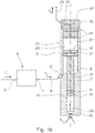
- the reference numeral 1 indicates an apparatus according to the present invention.
- the apparatus 1 includes a first hydraulic piston 11 movably arranged in a first cylinder housing 13 and a second hydraulic piston 15 movably arranged in a second cylinder housing 17.
- the first hydraulic piston 11 is mechanically connected to the second hydraulic piston 15 by means of a piston rod 19.
- the piston rod 19 is thus a connecting means between the first hydraulic piston 11 and the second hydraulic piston 15.
- the apparatus 1 is in fluid communication with a sampling device 3 which is provided with an inlet portion 5 and an outlet portion 7.
- the inlet portion 5 is in fluid communication with a well fluid
- the outlet portion 7 is in fluid communication, via a fluid line 8, with a dump chamber 9 in the apparatus 1.
- the fluid line 8 is connected to the apparatus 1 by means of a coupling device 8' which is attached, for example by means of a threaded connection, to a cut-out in the second cylinder housing 17.
- the cut-out is in fluid communication with the dump chamber 9 as indicated in the figures.
- the sampling device 3 may be a measuring device 3 comprising at least one sensor.
- the sampling device 3 may be a sample chamber, for example a tracer sample chamber.
- the sampling device 3 may include both a measuring device and a tracer sample chamber.
- the sampling device 3 includes the measuring device with the at least one sensor, whereas the tracer sample chamber is arranged in, for example defined by, a portion of the fluid line 8.
- the sampling device 3 is a tracer sample chamber
- this is provided with valves (not shown) arranged for example at the inlet portion 5 and the outlet portion 7.
- the fluid line 8 is provided with valves (not shown) arranged at the outlet portion 7 and at the coupling device 8', for example.
- the sampling device 3 is a measuring device comprising at least one sensor.
- the apparatus 1 according to the invention could just as well be used for a sampling device including a sample container such as said tracer sample chamber, or a combination of the measuring device and the sample container.
- the point of the invention is that the well-fluid sample is sucked into and through the sampling device 3 by means of the apparatus 1 according to the present invention.
- the dump chamber 9 is defined by the first piston 11, the first cylinder housing 13 and the portion of the piston rod 19 that is in the first cylinder housing 13 at any time.
- each of the pistons 11, 15 is provided with a seal 11' and 15', respectively.
- the area of a piston face 12 of the first piston 11 is larger than the area of a piston face 16 of the second piston 15.
- the piston rod 19 has a cross-sectional area which is equal to the cross-sectional area (and the piston face 16) of the second piston 15.
- the first cylinder housing 13 is provided with an end plug 21 attached to it by means of a threaded connection.
- the end plug 21 is provided with seals 21' to be able to form a fluid-tight connection between the first cylinder housing 13 and the end plug 21.
- the end plug 21, piston face 12 of the first piston 11 and the portion of the cylinder housing 13 which at all times is defined by said piston face 12 and an end face 21" of the end plug 21, define a first hydraulic chamber 23.
- the first hydraulic chamber 23 is arranged to accommodate a pressurized fluid such as a hydraulic liquid.
- the hydraulic liquid is carried into the chamber 23 via the end plug 21.
- the end plug 21 is further provided with a holding device in the form of a valve 25 which is arranged to be controllable both ways between an open position and a closed position.
- the control of the valve 25 can be performed by means of means that will be well known to a person skilled in the art.
- the valve 25 is in fluid communication with the first hydraulic chamber 23 via a fluid channel 27 and in fluid communication with a receiving unit, not shown, for hydraulic liquid from the hydraulic chamber 23 via an outlet line 29.
- the receiving unit may be, for example, a container, not shown, having a pressure, when filled with the fluid from the hydraulic chamber 23, lower than an ambient pressure in the well.
- the receiving unit may for example be somewhere higher up in the well or outside the well so that the fluid may selectively be bled off from the hydraulic chamber 23.
- valve 25 The purpose of the valve 25 is thus to allow the hydraulic liquid to be bled off from the hydraulic chamber 23.
- the second cylinder housing 17 is provided with an opening 31 for communication of well fluid between the well and the second cylinder housing 17.
- a second hydraulic chamber 33 is thus defined by the piston face 16 of the second piston 15, the portion of the cylinder housing 17 which at all times is defined by said piston face 16, and the opening 31.
- the opening 31 is a bore through a lower end portion of the second cylinder housing 17.
- the well fluid will be carried towards the piston face 16 of the second piston 15.
- the piston 15 will exert an upward force as is shown in the figures.
- the pressure of the fluid in the first hydraulic chamber 23 must be of such a magnitude that a downward force exerted by the first piston 11 is larger than the opposite force in consequence of the pressure of the well fluid in the second hydraulic chamber 33.
- the necessary pressure that will have to be supplied to the first hydraulic chamber 23 depends on the maximum well pressure to which the apparatus 1 is exposed to in the relevant situation of application.
- fluid at the desired pressure will be supplied to the hydraulic chamber 23 of the apparatus 1 before the apparatus 1 is run into the well.
- the hydraulic chamber 23 is pressurized as the apparatus 1 is being run into the well.
- this requires fluid communication with the surface or a pump/valve device from a possible container which is arranged to be selectively put into fluid communication with the chamber 23.
- a pump/valve device will complicate the apparatus 1 and is thus a less attractive solution.
- Figure 1a shows the apparatus 1 in its position of application just after the valve 25 in the end plug 21 has been brought from the closed position to the open position.
- the valve 25 is of a kind known per se, which is arranged to be remotely operated, for example from a vessel connected to the well.
- pressurized fluid from the first hydraulic chamber 23 will be bled off via the fluid channel 27 and the outlet line 29 and further to the receiving unit not shown.
- the fluid flow out of the first hydraulic chamber 23 is indicated by an arrow F b .
- the sampling device 3 is a measuring device comprising at least one sensor
- the flow of "exhaust fluid", i.e. fluid that has passed the measuring device 3 is illustrated by an arrow F e .
- the exhaust-fluid flow F e may be identical to F i .
- the measuring device 3 is of the gas-chromatograph type, for example, F e will be a mixture of the well-fluid flow F i and a carrier gas which is supplied from a carrier-gas container, not shown, which is in fluid communication with the measuring device 3, as will be known to a person skilled in the art.
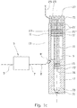
- Figure 1b shows the apparatus of figure 1a after the piston arrangement 15, 19, 11 has moved about half the stroke length in the cylinder housings 17, 13.
- the piston arrangement 15, 19, 11 will be moved upwards as long as the bleed-off of the fluid pressure in the first hydraulic chamber 23 is maintained, i.e. as long as the valve 25 is open and as long as the downward force from the first piston 11 is smaller than the opposite force from the second piston 15.
- valve 25 When the desired measurement has been achieved, the valve 25 is closed. By opening the valve 25 again after a certain time, either with the apparatus 1 in the same position in the well or after the apparatus 1 has been moved to another position, for example higher or lower in the well, another measurement can be carried out. Such “stepped” measurements may be repeated one or more times until the dump chamber 9 has reached its maximum volume as shown in figure 1c where the fluid flows F b , F w , F i and F e have ceased.
- the sampling device 3 comprises a measuring device with at least one sensor, it may be very important that the fluid flow F i into and through the at least one sensor of the measuring device 3 takes place at a controlled, stable flow rate.
- Such a controlled, stable flow rate is achieved by controlling the degree of opening of the valve 25.
- opening valve means that the position of the valve is not necessarily in its fully open position, but in a position different from fully closed, so that the desired flow rate of the fluid flow F i into and through the measuring device 3 is achieved.
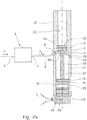
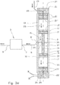
- Figures 2a-2c show an alternative embodiment of the apparatus shown in figure 1a-1c .
- the area of the piston face 12 of the first piston 11 is smaller than the area of the piston face 16 of the second piston 15.
- the piston rod 19 has a cross-sectional area which is smaller than the cross-sectional areas (and the piston faces 12, 16) of both the first piston 11 and the second piston 15.
- a chamber wall 35 provides a partition between the dump chamber 9 and a partition-wall chamber 37 which is further defined by a portion of the piston rod 19, the second cylinder housing 17 and the second piston 15.
- the chamber wall 35 is provided with an opening 39 which is complementarily adapted to the piston rod 19 and arranged coaxially with it.
- annular grooves are arranged for receiving a set of seals 41 (two shown in the figures) in order to provide, together with the piston rod 19, fluid-sealing between the partition-wall chamber 37 and the dump chamber 9.
- a substantial difference between the apparatus 1 shown in figures 1a-1c and the apparatus 1 shown in figures 2a-2c is that the latter does not need a closable first hydraulic chamber 23 which, in the embodiment shown in figures 1a-1c , initially contains a fluid at a pressure sufficient to counteract the movement of the piston arrangement 15, 19, 11.
- the first hydraulic chamber 23 may thus, but need not, be open towards the well as shown.
- an end portion of the second cylinder housing 17 is provided with an end plug 22 which bears many similarities to the end plug 21 shown in figures 1a-1c .
- the fluid flow F w is from the well, via the valve 26 and the fluid channel 28 and to the second hydraulic chamber 33.
- the apparatus 1 according to the exemplary embodiment shown in figures 2a-2c is run into the well with the piston arrangement 15, 19, 11 in the position shown in figure 2a .
- This means that the partition-wall chamber 37 is filled with a fluid, such as air or a liquid or a mixture thereof.
- a draining device in the form of a valve 43 is arranged in a fluid-communication channel in the second cylinder housing 17, near the chamber wall 35.
- valve 43 The purpose of the valve 43 is to allow the fluid present in the partition-wall chamber 37 to be bled off as the volume of said chamber 37 is being reduced in consequence of the fluid flow F w into the second hydraulic chamber 33 and consequent upward movement of the piston 15. In the embodiment shown, the fluid is bled off towards the well.
- the valve 43 thus enables a full movement of the piston arrangement 15, 19, 11 from the position which is shown in figure 2a to the position which is shown in figure 2c .
- the valve 43 is a one-way valve, but it is also conceivable for it to be a controllable valve. However, a controllable valve may complicate the apparatus 1 and is therefore not the primarily preferred solution.
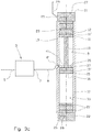
- Figures 3a-3c show yet another alternative embodiment of the apparatus 1 shown in figures 1a-1c and figures 2a-2c .
- the area of the piston face 12 of the first piston 11 is equal to the area of the piston face 16 of the second piston 15.
- the piston rod 19 has a cross-sectional area which is smaller than the cross-sectional area (and the piston faces 12, 16) of the first piston 11 and thus also that of the second piston 15.
- the apparatus 1 is provided with an end plug 21 and a valve 25 arranged in association with the first hydraulic chamber 23, in a manner corresponding to that shown in figures 1a-1c . Further, the apparatus 1 is provided with a second end plug 22 and a valve 26 arranged in association with the second hydraulic chamber 33, in a manner corresponding to that shown in figures 2a-2c .
- the latter end plug 22 and valve 26 are, in terms of operation, of the embodiment shown in figures 3a-3c .
- the pistons 11, 15 do not need to be of the same size.
- the piston arrangement 15, 19, 11 with associated cylinder housings 17, 13 shown in figures 2a-2c could be used also for the arrangement shown in figures 3a-3c .
- the volume in the partition-wall chamber 37 mentioned above will increase.
- the partition-wall chamber 37 is fluid-tight in consequence of seals 41 in the chamber wall 35 and the seal 15' in the second piston 15.
- an underpressure will form in the partition-wall chamber 37.
- the underpressure will act against an internal piston face 16' of the second piston 15 and thus exert an upward force which acts against the force from the first piston 12 in consequence of the pressurized fluid in the first hydraulic chamber 23.
- fluid must be evacuated from the dump chamber 9.
- the valve 26 In the embodiment shown, in which an end plug 22 is arranged in association with the second hydraulic chamber 33 as well, the valve 26 must be in an open position so that fluid is also allowed to evacuate from the second hydraulic chamber 33.
- Figure 3d shows the fluid flows through the apparatus 1 during said "charging”.
- valve 43 shown in figures 2a-2c may be superfluous in the embodiment shown in figures 3a-3c provided the "charging" is carried out from the position that is shown in figure 3c in which the second piston abuts against the chamber wall 35.
- An advantage of arranging an end plug 22 with an associated valve 26 in association with the second hydraulic chamber 33 as well, is that the well fluid F w may selectively be prevented from entering the chamber 33, for example while the apparatus 1 is being run into the well.
- the fluid in the first hydraulic chamber 23 may be supplied at a pressure which is sufficient to overcome the underpressure in the partition-wall chamber 37.
- the valve 26 may be used as a means of at least contributing to the control of the movement of the piston arrangement 15, 19, 11.
- the valve 26 controlling the inflow of well fluid into the second hydraulic chamber 33 while, at the same time, the valve 25, which controls the bleed-off of the pressurized fluid in the first hydraulic chamber 23, is at least partially open, the fluid pressure in the second hydraulic chamber 33 may be controlled into being positive, contributing to an upward movement of the piston arrangement 15, 19, 11, that is, or negative, reducing or braking an upward movement of the piston arrangement 15, 19, 11, that is.
- valve 25 associated with the first hydraulic chamber 23 may be fully or partially closed, and that the rate of motion of the piston arrangement 15, 19, 11 and thereby the rate of volume change in the dump chamber 9 is controlled by means of the valve 26 controlling the inflow of well fluid into the second hydraulic chamber 33. A pressure increase will then occur in the first hydraulic chamber 23.
Landscapes
- Life Sciences & Earth Sciences (AREA)
- Engineering & Computer Science (AREA)
- Mining & Mineral Resources (AREA)
- Geology (AREA)
- Physics & Mathematics (AREA)
- Geochemistry & Mineralogy (AREA)
- General Life Sciences & Earth Sciences (AREA)
- Fluid Mechanics (AREA)
- Environmental & Geological Engineering (AREA)
- Biochemistry (AREA)
- Pathology (AREA)
- Immunology (AREA)
- General Physics & Mathematics (AREA)
- General Health & Medical Sciences (AREA)
- Analytical Chemistry (AREA)
- Chemical & Material Sciences (AREA)
- Health & Medical Sciences (AREA)
- Hydrology & Water Resources (AREA)
- Sampling And Sample Adjustment (AREA)
- Fluid-Pressure Circuits (AREA)
Claims (16)
- Appareil (1) destiné à amener un échantillon de fluide de puits dans un puits à travers un dispositif d'échantillonnage (3), lequel présente une communication de fluide avec l'appareil (1), l'appareil (1) comprenant :- une chambre de basculement (9) pour recevoir l'échantillon de fluide de puits ;- un premier piston hydraulique (11) agencé dans un premier logement de cylindre (13) ;- un second piston hydraulique (15) agencé dans un second logement de cylindre (17) ;- une tige de piston (19) pour relier par voie mécanique le premier piston (11) au second piston (15) afin de former un agencement de piston (11, 15, 19), caractérisé en ce que la chambre de basculement (9) est définie par le premier piston (11) et une portion du premier logement de cylindre (13), et en ce que l'appareil (1) comprend en outre au moins un dispositif de maintien (25; 26), lequel est agencé de manière à commuter entre une position active, où l'agencement de piston (11, 15, 19) est maintenu fixe contre le déplacement, et une position inactive, où un déplacement de l'agencement de piston (11, 15, 19) par rapport aux logements de cylindre (13, 17) est permis, ledit déplacement de l'agencement de piston (11, 15, 19) étant provoqué au moyen d'un fluide de puits, lequel présente une communication de fluide avec le second piston hydraulique (15), de sorte que le déplacement provoque une augmentation d'un volume de la chambre de basculement (9) lorsque le dispositif de maintien (25; 26) se trouve dans sa position inactive.
- Appareil (1) selon la revendication 1, dans lequel l'aire d'une face de piston (12) du premier piston (11) est plus grande que l'aire de la face de piston (16) du second piston (15).
- Appareil selon la revendication 1 ou 2, dans lequel le premier logement de cylindre (13) est doté d'un bouchon terminal (21), dans lequel le bouchon terminal (21), une face de piston (12) du premier piston (11) et une portion du premier logement de cylindre (13) définissent une première chambre de logement de cylindre (23), laquelle est agencée pour loger un fluide sous pression, et dans lequel le dispositif de maintien (25; 26) est une soupape (25) agencée pour purger de manière sélective le fluide sous pression.
- Appareil (1) selon l'une quelconque des revendications précédentes, dans lequel le second piston (15) présente une communication de fluide continue avec le fluide de puits lorsque l'appareil se trouve dans sa position d'application.
- Appareil (1) selon la revendication 1, dans lequel l'aire d'une face de piston (12) du premier piston (11) est plus petite que l'aire de la face de piston (16) du second piston (15) ; dans lequel en particulier, le second logement de cylindre (17) est doté d'un bouchon terminal (22) ; dans lequel le bouchon terminal (22), la face de piston (16) du second piston (15) et une portion du second logement de cylindre (17) définissent une seconde chambre de logement de cylindre (33), laquelle est dotée du dispositif de maintien sous la forme d'une soupape (26), laquelle dans sa position active, coupe la communication de fluide du fluide de puits jusque dans la seconde chambre de logement de cylindre (33), et dans sa position inactive, permet une communication de fluide du fluide de puits jusque dans la seconde chambre de logement de cylindre (33).
- Appareil (1) selon la revendication 1, dans lequel la tige de piston (19) présente une section transversale, laquelle est plus petite que l'aire d'une face de piston (12) du premier piston (11) et que l'aire d'une face de piston (16) du second piston (15), et dans lequel une paroi de chambre (35) dotée d'une ouverture adaptée de manière complémentaire à la tige de piston (19) fournit une cloison entre la chambre de basculement (9) et une chambre à cloison de séparation (37) définie par une portion de la tige de piston (19), le second logement de cylindre (17), et le second piston (15).
- Appareil (1) selon la revendication 6, dans lequel au moins le premier logement de cylindre (13) est doté d'un bouchon terminal (21) ; dans lequel le bouchon terminal (21), la face de piston (12) du premier piston (11) et une portion du premier logement de cylindre (13) définissent une première chambre de logement de cylindre (23), laquelle est agencée de manière à loger un fluide sous pression, et dans lequel le dispositif de maintien (25 ; 26) est une soupape (25) agencée pour purger de manière sélective le fluide sous pression ; la soupape (25), dans sa position active, coupe la communication de fluide du fluide sous pression sortant de la première chambre de logement de cylindre (23), et dans sa position inactive, permet une communication de fluide du fluide sous pression hors de la première chambre de logement de cylindre (23), et dans lequel une pression dans la chambre à cloison de séparation (37) est inférieure à une pression atmosphérique au moins lorsqu'un volume dans la chambre de basculement (9) est sur un minimum, et dans lequel en particulier, une seconde chambre de logement de cylindre (33) définie par la face de second piston (16) et le second logement de cylindre (17) est agencée de manière à recevoir le fluide de puits, et dans lequel plus particulièrement, le second logement de cylindre (17) est doté d'un bouchon terminal (22), lequel est doté d'un dispositif de maintien (25; 26) sous la forme d'une soupape (26) afin de commander le débit entrant du fluide de puits jusque dans la seconde chambre de logement de cylindre (33), la soupape (26), dans sa position active, coupant la communication de fluide du fluide de puits jusque dans la seconde chambre de logement de cylindre (33), et dans sa position inactive, permettant une communication de fluide du fluide de puits jusque dans la seconde chambre de logement de cylindre (33).
- Système destiné à collecter un échantillon de puits à partir d'un puits, dans lequel le système inclut l'appareil (1) selon l'une quelconque des revendications précédentes et un dispositif d'échantillonnage (3) comprenant un dispositif de mesure doté d'au moins un capteur.
- Système selon la revendication 8, dans lequel le capteur inclut un chromatographe sélectionné parmi le groupe consistant en un chromatographe en phase gazeuse, un chromatographe en phase liquide, et un chromatographe à échange d'ions, ou une combinaison de ceux-ci.
- Système destiné à collecter un échantillon de puits, à partir d'un puits, le système incluant l'appareil (1) selon l'une quelconque des revendication 1 à 8, dans lequel le dispositif d'échantillonnage (3) comprend une chambre d'échantillon de traçage, laquelle est agencée pour isoler, au moyen de soupapes, un échantillon de fluide, lequel est extrait du puits au moyen de la chambre de basculement (9), et dans lequel le dispositif d'échantillonnage (3), les soupapes et une ligne de fluide en amont de la chambre d'échantillon de traçage sont dotés d'une surface interne, laquelle consiste en un matériau en grande partie non réactif quant à des substance transportées à partir du puits jusque dans la chambre d'échantillon de traçage, de sorte que des éléments traceurs amenés jusque dans la chambre d'échantillon de traçage peuvent être sortis de la chambre d'échantillon de traçage lorsque l'échantillon de fluide de puits est analysé.
- Système selon la revendication 8 ou 9, en combinaison avec la revendication 10, dans lequel le dispositif de mesure est placé en amont de la chambre d'échantillon de traçage, et dans lequel la chambre d'échantillon de traçage est agencée pour être isolée du dispositif de mesure et de la chambre de basculement au moyen de soupapes, et dans lequel, en particulier, la chambre d'échantillon de traçage inclut une portion d'une ligne de fluide (8) s'étendant entre une portion de sortie (7) du dispositif d'échantillonnage (3) et la chambre de basculement (9).
- Appareil (1) selon la revendication 1, dans lequel le dispositif de maintien est un dispositif de maintien mécanique pouvant être relâché, lequel dans sa position active, est configuré pour verrouiller l'agencement de piston (11, 15, 19) sur une position initiale, où le volume de la chambre de basculement (9) est sur un minimum.
- Procédé destiné à destiné à amener un échantillon de fluide de puits à travers un dispositif d'échantillonnage (3) dans un puits au moyen de l'appareil (1) selon la revendication 1, caractérisé en ce que le procédé comprend les étapes consistant à :agencer la chambre de basculement (9) avec un volume le plus petit possible, puis activer le dispositif de maintien (25; 26) de l'appareil (1) ;amener l'appareil (1) conjointement avec le dispositif d'échantillonnage (3) sur un endroit souhaité dans le puits, etlancer le déplacement de l'agencement de piston (15, 19, 11) en désactivant le au moins un dispositif de maintien (25; 26), de sorte qu'un fluide de puits entraîne le déplacement de l'agencement de piston (15, 19, 11), afin ainsi d'augmenter le volume de la chambre de basculement (9) et d'aspirer l'échantillon de fluide de puits à travers le dispositif d'échantillonnage (3).
- Procédé selon la revendication 13, dans lequel le procédé comprend en outre l'arrêt du déplacement de l'agencement de piston (15, 19, 11) en réactivant le dispositif de maintien comprenant une soupape (25; 26), de sorte que le fluide de puits n'est plus aspiré via le dispositif d'échantillonnage (3) et jusque dans la chambre de basculement (9).
- Procédé selon la revendication 13 ou 14, dans lequel le déplacement de l'agencement de piston (15, 19, 11) est facilité au moyen d'un fluide d'une chambre à cloison de séparation (37), le fluide présentant une pression inférieure à la pression atmosphérique au moins lorsque le volume de la chambre de basculement (9) est sur un minimum.
- Procédé selon l'une quelconque des revendications 13 à 15, dans lequel la chambre de basculement (9) est agencée avec le volume le plus petit possible avant que l'appareil (1) ne soit passé dans le puits.
Applications Claiming Priority (2)
| Application Number | Priority Date | Filing Date | Title |
|---|---|---|---|
| NO20141190A NO339638B1 (no) | 2014-10-03 | 2014-10-03 | Apparat og framgangsmåte for å tilveiebringe en fluidprøve i en brønn |
| PCT/NO2015/050178 WO2016053110A1 (fr) | 2014-10-03 | 2015-09-30 | Appareil et procédé d'obtention d'un échantillon fluidique dans un puits |
Publications (3)
| Publication Number | Publication Date |
|---|---|
| EP3201436A1 EP3201436A1 (fr) | 2017-08-09 |
| EP3201436A4 EP3201436A4 (fr) | 2018-05-09 |
| EP3201436B1 true EP3201436B1 (fr) | 2020-05-06 |
Family
ID=55631024
Family Applications (1)
| Application Number | Title | Priority Date | Filing Date |
|---|---|---|---|
| EP15846896.7A Active EP3201436B1 (fr) | 2014-10-03 | 2015-09-30 | Appareil et procédé d'obtention d'un échantillon fluidique dans un puits |
Country Status (6)
| Country | Link |
|---|---|
| US (2) | US20170254198A1 (fr) |
| EP (1) | EP3201436B1 (fr) |
| AU (1) | AU2015324684B2 (fr) |
| CA (1) | CA2963372C (fr) |
| NO (1) | NO339638B1 (fr) |
| WO (1) | WO2016053110A1 (fr) |
Families Citing this family (11)
| Publication number | Priority date | Publication date | Assignee | Title |
|---|---|---|---|---|
| GB201609285D0 (en) * | 2016-05-26 | 2016-07-13 | Metrol Tech Ltd | Method to manipulate a well |
| GB2550862B (en) * | 2016-05-26 | 2020-02-05 | Metrol Tech Ltd | Method to manipulate a well |
| US10677053B2 (en) * | 2016-08-30 | 2020-06-09 | Schlumberger Technology Corporation | Fluid compensation system for downhole sampling bottle |
| AU2018218180B2 (en) * | 2017-02-07 | 2023-03-02 | Willingdon Properties Pty. Ltd. | Improvements in fluid sampling |
| CN108844782A (zh) * | 2018-08-15 | 2018-11-20 | 成都赋阳技术开发有限公司 | 一种用于水质检测的水质取样设备 |
| CN112211629B (zh) * | 2019-07-10 | 2023-07-18 | 中国石油化工股份有限公司 | 一种混浆获取装置及其使用方法 |
| CN112012735B (zh) * | 2020-09-08 | 2023-07-07 | 中国石油天然气集团有限公司 | 随钻地层压力测量采样室 |
| US12601257B2 (en) | 2020-10-08 | 2026-04-14 | Weatherford Technology Holdings, Llc | Fluid sampler tool and associated system and method |
| GB2602825B (en) * | 2021-01-18 | 2023-05-17 | Proserv Uk Ltd | Method and system for testing a fluid sample |
| CN114370270B (zh) * | 2022-01-14 | 2024-02-23 | 中国石油大学(华东) | 一种机械采油井口取样保护装置 |
| US12571306B1 (en) * | 2024-09-09 | 2026-03-10 | Schlumberger Technology Corporation | Pressure compensated locking sampling tool |
Family Cites Families (32)
| Publication number | Priority date | Publication date | Assignee | Title |
|---|---|---|---|---|
| US2459148A (en) * | 1944-09-20 | 1949-01-18 | Niels A Christensen | Fluid control apparatus |
| US3295615A (en) * | 1965-10-22 | 1967-01-03 | Schlumberger Well Surv Corp | Formation-testing apparatus |
| US4739654A (en) * | 1986-10-08 | 1988-04-26 | Conoco Inc. | Method and apparatus for downhole chromatography |
| US4893505A (en) | 1988-03-30 | 1990-01-16 | Western Atlas International, Inc. | Subsurface formation testing apparatus |
| US5230244A (en) * | 1990-06-28 | 1993-07-27 | Halliburton Logging Services, Inc. | Formation flush pump system for use in a wireline formation test tool |
| US5377755A (en) * | 1992-11-16 | 1995-01-03 | Western Atlas International, Inc. | Method and apparatus for acquiring and processing subsurface samples of connate fluid |
| US5303775A (en) | 1992-11-16 | 1994-04-19 | Western Atlas International, Inc. | Method and apparatus for acquiring and processing subsurface samples of connate fluid |
| GB2276608B (en) | 1993-03-18 | 1996-01-10 | Atomic Energy Authority Uk | Fluid sampler |
| US6334489B1 (en) | 1999-07-19 | 2002-01-01 | Wood Group Logging Services Holding Inc. | Determining subsurface fluid properties using a downhole device |
| US6386017B1 (en) * | 1999-11-24 | 2002-05-14 | Mt. Fury Company, Inc. | System and method for measurement and control of suspended solids in a fluid |
| US6437326B1 (en) | 2000-06-27 | 2002-08-20 | Schlumberger Technology Corporation | Permanent optical sensor downhole fluid analysis systems |
| US6659177B2 (en) | 2000-11-14 | 2003-12-09 | Schlumberger Technology Corporation | Reduced contamination sampling |
| US6668924B2 (en) | 2000-11-14 | 2003-12-30 | Schlumberger Technology Corporation | Reduced contamination sampling |
| US7246664B2 (en) | 2001-09-19 | 2007-07-24 | Baker Hughes Incorporated | Dual piston, single phase sampling mechanism and procedure |
| US8210260B2 (en) | 2002-06-28 | 2012-07-03 | Schlumberger Technology Corporation | Single pump focused sampling |
| US6986282B2 (en) | 2003-02-18 | 2006-01-17 | Schlumberger Technology Corporation | Method and apparatus for determining downhole pressures during a drilling operation |
| US7140436B2 (en) * | 2003-04-29 | 2006-11-28 | Schlumberger Technology Corporation | Apparatus and method for controlling the pressure of fluid within a sample chamber |
| US7124819B2 (en) * | 2003-12-01 | 2006-10-24 | Schlumberger Technology Corporation | Downhole fluid pumping apparatus and method |
| US6966234B2 (en) * | 2004-01-14 | 2005-11-22 | Schlumberger Technology Corporation | Real-time monitoring and control of reservoir fluid sample capture |
| US20060198742A1 (en) | 2005-03-07 | 2006-09-07 | Baker Hughes, Incorporated | Downhole uses of piezoelectric motors |
| US7384453B2 (en) | 2005-12-07 | 2008-06-10 | Schlumberger Technology Corporation | Self-contained chromatography system |
| US20080087470A1 (en) * | 2005-12-19 | 2008-04-17 | Schlumberger Technology Corporation | Formation Evaluation While Drilling |
| US7614294B2 (en) * | 2006-09-18 | 2009-11-10 | Schlumberger Technology Corporation | Systems and methods for downhole fluid compatibility |
| US8146415B2 (en) | 2008-05-27 | 2012-04-03 | Baker Hughes Incorporated | Downhole gas chromatograph |
| US8581591B2 (en) * | 2008-06-11 | 2013-11-12 | Halliburton Energy Services, Inc. | Method and system of determining an electrical property of a formation fluid |
| NO334205B1 (no) | 2008-12-22 | 2014-01-13 | Shore Tec Consult As | Datainnsamlingsanordning og fremgangsmåte for å fjerne forurensninger fra en brønns borehullsvegg før in situ innsamling av formasjonsdata fra borehullsveggen |
| US8448703B2 (en) * | 2009-11-16 | 2013-05-28 | Schlumberger Technology Corporation | Downhole formation tester apparatus and methods |
| US8672026B2 (en) * | 2010-07-23 | 2014-03-18 | Halliburton Energy Services, Inc. | Fluid control in reservior fluid sampling tools |
| US8695414B2 (en) * | 2011-07-12 | 2014-04-15 | Halliburton Energy Services, Inc. | High pressure and flow rate pump useful in formation fluid sample testing |
| NO335176B1 (no) | 2012-02-16 | 2014-10-13 | Petrotech As | Anordning og framgangsmåte for brønntesting |
| WO2013147616A1 (fr) * | 2012-03-30 | 2013-10-03 | Proserv Norge As | Procédé et dispositif d'échantillonnage sous-marin |
| EP3025025A1 (fr) * | 2013-10-03 | 2016-06-01 | Halliburton Energy Services, Inc. | Chambre d'échantillonnage à accepteur réactif aux sulfure d'hydrogène |
-
2014
- 2014-10-03 NO NO20141190A patent/NO339638B1/no unknown
-
2015
- 2015-09-30 WO PCT/NO2015/050178 patent/WO2016053110A1/fr not_active Ceased
- 2015-09-30 EP EP15846896.7A patent/EP3201436B1/fr active Active
- 2015-09-30 AU AU2015324684A patent/AU2015324684B2/en active Active
- 2015-09-30 US US15/514,176 patent/US20170254198A1/en not_active Abandoned
- 2015-09-30 CA CA2963372A patent/CA2963372C/fr active Active
-
2020
- 2020-01-23 US US16/750,709 patent/US11603758B2/en active Active
Non-Patent Citations (1)
| Title |
|---|
| None * |
Also Published As
| Publication number | Publication date |
|---|---|
| AU2015324684B2 (en) | 2020-03-26 |
| NO20141190A1 (no) | 2016-04-04 |
| EP3201436A1 (fr) | 2017-08-09 |
| US20170254198A1 (en) | 2017-09-07 |
| WO2016053110A1 (fr) | 2016-04-07 |
| NO339638B1 (no) | 2017-01-16 |
| US11603758B2 (en) | 2023-03-14 |
| US20200157936A1 (en) | 2020-05-21 |
| AU2015324684A1 (en) | 2017-03-23 |
| CA2963372C (fr) | 2023-11-07 |
| EP3201436A4 (fr) | 2018-05-09 |
| CA2963372A1 (fr) | 2016-04-07 |
Similar Documents
| Publication | Publication Date | Title |
|---|---|---|
| US11603758B2 (en) | Apparatus for providing a fluid sample in a well | |
| EP2852825B1 (fr) | Procédé et appareil de test automatique de la sédimentation de boues à pression élevée et à température élevée | |
| US8146415B2 (en) | Downhole gas chromatograph | |
| KR101606686B1 (ko) | 시추공 깊이별 지하수 시료 채취 장치 | |
| US8636478B2 (en) | Sensor assembly for determining fluid properties in a subsurface well | |
| NO174939B (no) | Fluidprövetaker med forsinket åpning. | |
| CN102706786A (zh) | 一种动态泥页岩孔隙压力传递实验装置 | |
| NO312785B1 (no) | Fremgangsmåte og instrument for å fremskaffe pröver av formasjonsfluid | |
| NO20101452A1 (no) | Fremgangsmåte og apparat for innhenting av brønnhullsprøve | |
| US20070158065A1 (en) | Zone isolation assembly array for isolating a plurality of fluid zones in a subsurface well | |
| CN104838089B (zh) | 用于监控天然气地质储藏的高压流体采样器 | |
| KR20150047884A (ko) | 용존가스를 포함하는 장심도 지하수용 시료채취장치 및 채취방법 | |
| EP0526177B1 (fr) | Dispositif pour séparer des échantillons de liquides sous haute pression | |
| CN113217502B (zh) | 伪三轴保压加载装置的活塞杆保压推送装置 | |
| RU194160U1 (ru) | Устройство для отбора глубинных проб | |
| CN207488181U (zh) | 井下抽样检测装置 | |
| US7121347B2 (en) | Liquid sampler | |
| SU1239299A1 (ru) | Скважинный пробоотборник | |
| RU2440495C1 (ru) | Приемная камера глубинного пробоотборника для отбора проб высоковязкой нефти и донного осадка | |
| US20190234211A1 (en) | Formation fluid sampling module | |
| EP4731874A1 (fr) | Procédé et appareil pour mesurer la densité sous pression dans une boucle d'échantillonnage | |
| US20150159483A1 (en) | Apparatus and Method for Obtaining Formation Fluid Samples Utilizing a Flow Control Device in a Sample Tank |
Legal Events
| Date | Code | Title | Description |
|---|---|---|---|
| STAA | Information on the status of an ep patent application or granted ep patent |
Free format text: STATUS: THE INTERNATIONAL PUBLICATION HAS BEEN MADE |
|
| PUAI | Public reference made under article 153(3) epc to a published international application that has entered the european phase |
Free format text: ORIGINAL CODE: 0009012 |
|
| STAA | Information on the status of an ep patent application or granted ep patent |
Free format text: STATUS: REQUEST FOR EXAMINATION WAS MADE |
|
| 17P | Request for examination filed |
Effective date: 20170404 |
|
| AK | Designated contracting states |
Kind code of ref document: A1 Designated state(s): AL AT BE BG CH CY CZ DE DK EE ES FI FR GB GR HR HU IE IS IT LI LT LU LV MC MK MT NL NO PL PT RO RS SE SI SK SM TR |
|
| AX | Request for extension of the european patent |
Extension state: BA ME |
|
| DAV | Request for validation of the european patent (deleted) | ||
| DAX | Request for extension of the european patent (deleted) | ||
| A4 | Supplementary search report drawn up and despatched |
Effective date: 20180409 |
|
| RIC1 | Information provided on ipc code assigned before grant |
Ipc: E21B 49/10 20060101ALI20180403BHEP Ipc: G01N 1/10 20060101ALI20180403BHEP Ipc: E21B 49/08 20060101AFI20180403BHEP |
|
| GRAP | Despatch of communication of intention to grant a patent |
Free format text: ORIGINAL CODE: EPIDOSNIGR1 |
|
| STAA | Information on the status of an ep patent application or granted ep patent |
Free format text: STATUS: GRANT OF PATENT IS INTENDED |
|
| INTG | Intention to grant announced |
Effective date: 20191202 |
|
| GRAS | Grant fee paid |
Free format text: ORIGINAL CODE: EPIDOSNIGR3 |
|
| GRAA | (expected) grant |
Free format text: ORIGINAL CODE: 0009210 |
|
| STAA | Information on the status of an ep patent application or granted ep patent |
Free format text: STATUS: THE PATENT HAS BEEN GRANTED |
|
| AK | Designated contracting states |
Kind code of ref document: B1 Designated state(s): AL AT BE BG CH CY CZ DE DK EE ES FI FR GB GR HR HU IE IS IT LI LT LU LV MC MK MT NL NO PL PT RO RS SE SI SK SM TR |
|
| REG | Reference to a national code |
Ref country code: GB Ref legal event code: FG4D |
|
| REG | Reference to a national code |
Ref country code: CH Ref legal event code: EP Ref country code: AT Ref legal event code: REF Ref document number: 1267004 Country of ref document: AT Kind code of ref document: T Effective date: 20200515 |
|
| REG | Reference to a national code |
Ref country code: IE Ref legal event code: FG4D |
|
| REG | Reference to a national code |
Ref country code: DE Ref legal event code: R096 Ref document number: 602015052491 Country of ref document: DE |
|
| REG | Reference to a national code |
Ref country code: LT Ref legal event code: MG4D |
|
| REG | Reference to a national code |
Ref country code: NL Ref legal event code: MP Effective date: 20200506 |
|
| PG25 | Lapsed in a contracting state [announced via postgrant information from national office to epo] |
Ref country code: PT Free format text: LAPSE BECAUSE OF FAILURE TO SUBMIT A TRANSLATION OF THE DESCRIPTION OR TO PAY THE FEE WITHIN THE PRESCRIBED TIME-LIMIT Effective date: 20200907 Ref country code: LT Free format text: LAPSE BECAUSE OF FAILURE TO SUBMIT A TRANSLATION OF THE DESCRIPTION OR TO PAY THE FEE WITHIN THE PRESCRIBED TIME-LIMIT Effective date: 20200506 Ref country code: FI Free format text: LAPSE BECAUSE OF FAILURE TO SUBMIT A TRANSLATION OF THE DESCRIPTION OR TO PAY THE FEE WITHIN THE PRESCRIBED TIME-LIMIT Effective date: 20200506 Ref country code: SE Free format text: LAPSE BECAUSE OF FAILURE TO SUBMIT A TRANSLATION OF THE DESCRIPTION OR TO PAY THE FEE WITHIN THE PRESCRIBED TIME-LIMIT Effective date: 20200506 Ref country code: NO Free format text: LAPSE BECAUSE OF FAILURE TO SUBMIT A TRANSLATION OF THE DESCRIPTION OR TO PAY THE FEE WITHIN THE PRESCRIBED TIME-LIMIT Effective date: 20200806 Ref country code: GR Free format text: LAPSE BECAUSE OF FAILURE TO SUBMIT A TRANSLATION OF THE DESCRIPTION OR TO PAY THE FEE WITHIN THE PRESCRIBED TIME-LIMIT Effective date: 20200807 Ref country code: IS Free format text: LAPSE BECAUSE OF FAILURE TO SUBMIT A TRANSLATION OF THE DESCRIPTION OR TO PAY THE FEE WITHIN THE PRESCRIBED TIME-LIMIT Effective date: 20200906 |
|
| PG25 | Lapsed in a contracting state [announced via postgrant information from national office to epo] |
Ref country code: BG Free format text: LAPSE BECAUSE OF FAILURE TO SUBMIT A TRANSLATION OF THE DESCRIPTION OR TO PAY THE FEE WITHIN THE PRESCRIBED TIME-LIMIT Effective date: 20200806 Ref country code: RS Free format text: LAPSE BECAUSE OF FAILURE TO SUBMIT A TRANSLATION OF THE DESCRIPTION OR TO PAY THE FEE WITHIN THE PRESCRIBED TIME-LIMIT Effective date: 20200506 Ref country code: HR Free format text: LAPSE BECAUSE OF FAILURE TO SUBMIT A TRANSLATION OF THE DESCRIPTION OR TO PAY THE FEE WITHIN THE PRESCRIBED TIME-LIMIT Effective date: 20200506 Ref country code: LV Free format text: LAPSE BECAUSE OF FAILURE TO SUBMIT A TRANSLATION OF THE DESCRIPTION OR TO PAY THE FEE WITHIN THE PRESCRIBED TIME-LIMIT Effective date: 20200506 |
|
| REG | Reference to a national code |
Ref country code: AT Ref legal event code: MK05 Ref document number: 1267004 Country of ref document: AT Kind code of ref document: T Effective date: 20200506 |
|
| PG25 | Lapsed in a contracting state [announced via postgrant information from national office to epo] |
Ref country code: AL Free format text: LAPSE BECAUSE OF FAILURE TO SUBMIT A TRANSLATION OF THE DESCRIPTION OR TO PAY THE FEE WITHIN THE PRESCRIBED TIME-LIMIT Effective date: 20200506 Ref country code: NL Free format text: LAPSE BECAUSE OF FAILURE TO SUBMIT A TRANSLATION OF THE DESCRIPTION OR TO PAY THE FEE WITHIN THE PRESCRIBED TIME-LIMIT Effective date: 20200506 |
|
| PG25 | Lapsed in a contracting state [announced via postgrant information from national office to epo] |
Ref country code: EE Free format text: LAPSE BECAUSE OF FAILURE TO SUBMIT A TRANSLATION OF THE DESCRIPTION OR TO PAY THE FEE WITHIN THE PRESCRIBED TIME-LIMIT Effective date: 20200506 Ref country code: SM Free format text: LAPSE BECAUSE OF FAILURE TO SUBMIT A TRANSLATION OF THE DESCRIPTION OR TO PAY THE FEE WITHIN THE PRESCRIBED TIME-LIMIT Effective date: 20200506 Ref country code: DK Free format text: LAPSE BECAUSE OF FAILURE TO SUBMIT A TRANSLATION OF THE DESCRIPTION OR TO PAY THE FEE WITHIN THE PRESCRIBED TIME-LIMIT Effective date: 20200506 Ref country code: AT Free format text: LAPSE BECAUSE OF FAILURE TO SUBMIT A TRANSLATION OF THE DESCRIPTION OR TO PAY THE FEE WITHIN THE PRESCRIBED TIME-LIMIT Effective date: 20200506 Ref country code: ES Free format text: LAPSE BECAUSE OF FAILURE TO SUBMIT A TRANSLATION OF THE DESCRIPTION OR TO PAY THE FEE WITHIN THE PRESCRIBED TIME-LIMIT Effective date: 20200506 Ref country code: CZ Free format text: LAPSE BECAUSE OF FAILURE TO SUBMIT A TRANSLATION OF THE DESCRIPTION OR TO PAY THE FEE WITHIN THE PRESCRIBED TIME-LIMIT Effective date: 20200506 Ref country code: RO Free format text: LAPSE BECAUSE OF FAILURE TO SUBMIT A TRANSLATION OF THE DESCRIPTION OR TO PAY THE FEE WITHIN THE PRESCRIBED TIME-LIMIT Effective date: 20200506 Ref country code: IT Free format text: LAPSE BECAUSE OF FAILURE TO SUBMIT A TRANSLATION OF THE DESCRIPTION OR TO PAY THE FEE WITHIN THE PRESCRIBED TIME-LIMIT Effective date: 20200506 |
|
| REG | Reference to a national code |
Ref country code: DE Ref legal event code: R097 Ref document number: 602015052491 Country of ref document: DE |
|
| PG25 | Lapsed in a contracting state [announced via postgrant information from national office to epo] |
Ref country code: PL Free format text: LAPSE BECAUSE OF FAILURE TO SUBMIT A TRANSLATION OF THE DESCRIPTION OR TO PAY THE FEE WITHIN THE PRESCRIBED TIME-LIMIT Effective date: 20200506 Ref country code: SK Free format text: LAPSE BECAUSE OF FAILURE TO SUBMIT A TRANSLATION OF THE DESCRIPTION OR TO PAY THE FEE WITHIN THE PRESCRIBED TIME-LIMIT Effective date: 20200506 |
|
| PLBE | No opposition filed within time limit |
Free format text: ORIGINAL CODE: 0009261 |
|
| STAA | Information on the status of an ep patent application or granted ep patent |
Free format text: STATUS: NO OPPOSITION FILED WITHIN TIME LIMIT |
|
| REG | Reference to a national code |
Ref country code: DE Ref legal event code: R119 Ref document number: 602015052491 Country of ref document: DE |
|
| 26N | No opposition filed |
Effective date: 20210209 |
|
| PG25 | Lapsed in a contracting state [announced via postgrant information from national office to epo] |
Ref country code: MC Free format text: LAPSE BECAUSE OF FAILURE TO SUBMIT A TRANSLATION OF THE DESCRIPTION OR TO PAY THE FEE WITHIN THE PRESCRIBED TIME-LIMIT Effective date: 20200506 |
|
| REG | Reference to a national code |
Ref country code: CH Ref legal event code: PL |
|
| PG25 | Lapsed in a contracting state [announced via postgrant information from national office to epo] |
Ref country code: SI Free format text: LAPSE BECAUSE OF FAILURE TO SUBMIT A TRANSLATION OF THE DESCRIPTION OR TO PAY THE FEE WITHIN THE PRESCRIBED TIME-LIMIT Effective date: 20200506 |
|
| REG | Reference to a national code |
Ref country code: BE Ref legal event code: MM Effective date: 20200930 |
|
| PG25 | Lapsed in a contracting state [announced via postgrant information from national office to epo] |
Ref country code: LU Free format text: LAPSE BECAUSE OF NON-PAYMENT OF DUE FEES Effective date: 20200930 |
|
| PG25 | Lapsed in a contracting state [announced via postgrant information from national office to epo] |
Ref country code: FR Free format text: LAPSE BECAUSE OF NON-PAYMENT OF DUE FEES Effective date: 20200930 Ref country code: DE Free format text: LAPSE BECAUSE OF NON-PAYMENT OF DUE FEES Effective date: 20210401 |
|
| PG25 | Lapsed in a contracting state [announced via postgrant information from national office to epo] |
Ref country code: LI Free format text: LAPSE BECAUSE OF NON-PAYMENT OF DUE FEES Effective date: 20200930 Ref country code: IE Free format text: LAPSE BECAUSE OF NON-PAYMENT OF DUE FEES Effective date: 20200930 Ref country code: BE Free format text: LAPSE BECAUSE OF NON-PAYMENT OF DUE FEES Effective date: 20200930 Ref country code: CH Free format text: LAPSE BECAUSE OF NON-PAYMENT OF DUE FEES Effective date: 20200930 |
|
| PG25 | Lapsed in a contracting state [announced via postgrant information from national office to epo] |
Ref country code: TR Free format text: LAPSE BECAUSE OF FAILURE TO SUBMIT A TRANSLATION OF THE DESCRIPTION OR TO PAY THE FEE WITHIN THE PRESCRIBED TIME-LIMIT Effective date: 20200506 Ref country code: MT Free format text: LAPSE BECAUSE OF FAILURE TO SUBMIT A TRANSLATION OF THE DESCRIPTION OR TO PAY THE FEE WITHIN THE PRESCRIBED TIME-LIMIT Effective date: 20200506 Ref country code: CY Free format text: LAPSE BECAUSE OF FAILURE TO SUBMIT A TRANSLATION OF THE DESCRIPTION OR TO PAY THE FEE WITHIN THE PRESCRIBED TIME-LIMIT Effective date: 20200506 |
|
| PG25 | Lapsed in a contracting state [announced via postgrant information from national office to epo] |
Ref country code: MK Free format text: LAPSE BECAUSE OF FAILURE TO SUBMIT A TRANSLATION OF THE DESCRIPTION OR TO PAY THE FEE WITHIN THE PRESCRIBED TIME-LIMIT Effective date: 20200506 |
|
| P01 | Opt-out of the competence of the unified patent court (upc) registered |
Effective date: 20230512 |
|
| REG | Reference to a national code |
Ref country code: GB Ref legal event code: S117 Free format text: REQUEST FILED; REQUEST FOR CORRECTION UNDER SECTION 117 FILED ON 09 OCTOBER 2024 |
|
| REG | Reference to a national code |
Ref country code: GB Ref legal event code: S117 Free format text: CORRECTIONS ALLOWED; REQUEST FOR CORRECTION UNDER SECTION 117 FILED ON 09 OCTOBER 2024 WAS ALLOWED ON 04 DECEMBER 2024 |
|
| REG | Reference to a national code |
Ref country code: GB Ref legal event code: 732E Free format text: REGISTERED BETWEEN 20250403 AND 20250409 |
|
| PGFP | Annual fee paid to national office [announced via postgrant information from national office to epo] |
Ref country code: GB Payment date: 20250807 Year of fee payment: 11 |