EP3201441B1 - Elektromagnetische aktor für einem brennkraftmaschine - Google Patents
Elektromagnetische aktor für einem brennkraftmaschine Download PDFInfo
- Publication number
- EP3201441B1 EP3201441B1 EP15788455.2A EP15788455A EP3201441B1 EP 3201441 B1 EP3201441 B1 EP 3201441B1 EP 15788455 A EP15788455 A EP 15788455A EP 3201441 B1 EP3201441 B1 EP 3201441B1
- Authority
- EP
- European Patent Office
- Prior art keywords
- primary
- electromagnetic actuator
- coil
- bore
- core
- Prior art date
- Legal status (The legal status is an assumption and is not a legal conclusion. Google has not performed a legal analysis and makes no representation as to the accuracy of the status listed.)
- Active
Links
- 238000002485 combustion reaction Methods 0.000 title claims description 21
- 230000005291 magnetic effect Effects 0.000 claims description 13
- 230000005294 ferromagnetic effect Effects 0.000 claims description 11
- 238000001816 cooling Methods 0.000 description 11
- 239000012530 fluid Substances 0.000 description 8
- 208000031968 Cadaver Diseases 0.000 description 6
- 230000008901 benefit Effects 0.000 description 5
- 239000007789 gas Substances 0.000 description 4
- 238000000034 method Methods 0.000 description 4
- 239000012809 cooling fluid Substances 0.000 description 3
- 238000002347 injection Methods 0.000 description 2
- 239000007924 injection Substances 0.000 description 2
- 230000005540 biological transmission Effects 0.000 description 1
- 230000015556 catabolic process Effects 0.000 description 1
- 238000004891 communication Methods 0.000 description 1
- 230000006835 compression Effects 0.000 description 1
- 238000007906 compression Methods 0.000 description 1
- 238000010276 construction Methods 0.000 description 1
- 239000002826 coolant Substances 0.000 description 1
- 238000011161 development Methods 0.000 description 1
- 238000006073 displacement reaction Methods 0.000 description 1
- 230000005672 electromagnetic field Effects 0.000 description 1
- 238000010438 heat treatment Methods 0.000 description 1
- 230000007257 malfunction Effects 0.000 description 1
- 230000002093 peripheral effect Effects 0.000 description 1
- 238000004064 recycling Methods 0.000 description 1
- 230000001105 regulatory effect Effects 0.000 description 1
- 238000012546 transfer Methods 0.000 description 1
- 238000013519 translation Methods 0.000 description 1
- XLYOFNOQVPJJNP-UHFFFAOYSA-N water Substances O XLYOFNOQVPJJNP-UHFFFAOYSA-N 0.000 description 1
Images



Classifications
-
- F—MECHANICAL ENGINEERING; LIGHTING; HEATING; WEAPONS; BLASTING
- F01—MACHINES OR ENGINES IN GENERAL; ENGINE PLANTS IN GENERAL; STEAM ENGINES
- F01L—CYCLICALLY OPERATING VALVES FOR MACHINES OR ENGINES
- F01L9/00—Valve-gear or valve arrangements actuated non-mechanically
- F01L9/20—Valve-gear or valve arrangements actuated non-mechanically by electric means
- F01L9/21—Valve-gear or valve arrangements actuated non-mechanically by electric means actuated by solenoids
- F01L2009/2115—Moving coil actuators
-
- F—MECHANICAL ENGINEERING; LIGHTING; HEATING; WEAPONS; BLASTING
- F01—MACHINES OR ENGINES IN GENERAL; ENGINE PLANTS IN GENERAL; STEAM ENGINES
- F01L—CYCLICALLY OPERATING VALVES FOR MACHINES OR ENGINES
- F01L9/00—Valve-gear or valve arrangements actuated non-mechanically
- F01L9/20—Valve-gear or valve arrangements actuated non-mechanically by electric means
- F01L9/21—Valve-gear or valve arrangements actuated non-mechanically by electric means actuated by solenoids
- F01L2009/2157—Actuator cooling means
Definitions
- the invention relates to the control of valves in an internal combustion engine. More specifically, it relates to an electromagnetic actuator for a valve in such an engine.
- valve control must meet the following constraints. First, the movement of the valves must be rapid and precise, to facilitate the admission, respectively the evacuation, of the gases. Then, the valve stroke must be sufficient to guarantee a large flow of gases, whether it is intake or exhaust. Finally, the forces transmitted to the valves must be significant (especially during evacuation), to overcome the pressure prevailing in the combustion chamber.
- valves in internal combustion engines are carried out mechanically by a distribution system comprising one or more camshaft (s) which drive the valves, either directly or indirectly via rocker arms.
- a camshaft is coupled in rotation to the crankshaft by a belt or a timing chain.
- valve control is electromagnetic actuation.
- each valve is driven by means of an electromagnetic actuator.
- One or more magnets generate an electromagnetic field capable of move, by the force of Laplace, a support on which is wound a coil traversed by an electric current and with which the valve is integral.
- certain engines generally engines developing a large power, may require the use, for the same cylinder, of two intake valves and two exhaust valves.
- One objective is to propose an electromagnetic actuator which responds to all of the constraints associated with valve control: good speed, good control, sufficient valve stroke, importance of the forces transmitted, and which is adaptable to high power motors.
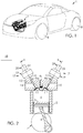
- a motor vehicle 1 is represented, here a particular vehicle, but it could be any other type of vehicle: utility, truck, construction machine.
- the vehicle 1 is equipped with an internal combustion engine 2 provided with cylinders 3 defining combustion chambers 4 and in which pistons 5 are slidably connected, by connecting rods 6, to a crankshaft 7 whose rotation drives the wheels 8 of vehicle 1 via a transmission (not shown).
- an internal combustion engine 2 provided with cylinders 3 defining combustion chambers 4 and in which pistons 5 are slidably connected, by connecting rods 6, to a crankshaft 7 whose rotation drives the wheels 8 of vehicle 1 via a transmission (not shown).
- the engine 2 comprises, for each cylinder 3, four valves 9 distributed in pairs, namely two intake valves 9a and two exhaust valves 9b .
- valves 9 In the remainder of this description, we will speak of valves 9, without making any particular reference to their use for intake or exhaust.
- Each valve 9 comprises a rod 10 which extends along a central X axis which defines an axial direction. At one end of the rod 10 is formed a head 11. Each valve 9 is movable in translation relative to a cylinder head 12 of the engine 2 between a closed position in which the head 11 of the valve 9 is pressed against a seat 13 for close off an intake duct 14 (or, respectively, an exhaust duct 15 ) and an open position in which the head 11 is moved away from the seat 13 to put the cylinder 3 in communication with the intake duct 14 (or, respectively, the exhaust duct 15 ).
- the engine 2 is of the direct injection diesel type and comprises, for this purpose, an injector 16 which opens directly into the combustion chamber 4 , but it could be any other type of combustion engine internal: petrol, indirect injection, hybrid.
- Each valve 9 is controlled in position by an electromagnetic actuator 17 .
- This actuator 17 is itself controlled by a computerized control unit 18 equipped with a programmable processor.
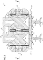
- the actuator 17 is shown in section on the figures 3 and 5 respectively according to a first and a second embodiment and in exploded view on the figure 4 , according to the first embodiment.
- the actuator 17 comprises an armature 19 as well as two crews 20, 21 mobiles, namely a primary mobile crew 20 and a secondary mobile crew 21 .
- the armature 19 comprises a primary bore 29 and a secondary bore 30 , adjacent to the primary bore 29 , in which the primary core 24 and the secondary core 26 are received respectively, the primary and secondary bores 29, 30 being formed. jointly in the pole pieces 23a, 23b and the magnet 22.
- the cover 28 is provided with a plate 31 and two fingers 32 capable of being housed each in one of the primary and secondary cores 24, 26 .
- the two fingers 32 are spaced from each other by a center distance C1 slightly smaller than a center distance P1 between the primary bore 29 and the secondary bore 30 which causes a reduction in the air gaps 25, 27 primary and secondary in a central region of the electromagnetic actuator 17 .
- the primary movable element 20 comprises a primary carcass 33 , an upper primary coil 34 , a lower primary coil 35 and a valve 9.
- the primary carcass 33 comprises a tubular body 36 open at an upper end 37 and provided with an upper annular groove 38 and a lower annular groove 39 in which are respectively housed the upper primary coil 34 and the lower primary coil 35 .
- the primary carcass 33 comprises at a lower end, a bottom 40 onto which the valve 9 is screwed by means of screws 41.
- the valve 9 is welded to the bottom 40 of the carcass 33 .
- the secondary movable element 21 comprises a secondary carcass 42 , an upper secondary coil 43 , a lower secondary coil 44 and a valve 9.
- the secondary carcass 42 comprises a tubular body 45 open at an upper end 46 and provided with an upper annular groove 47 and a lower annular groove 48 in which the upper primary coil 43 and lower primary coil 44 are respectively housed.
- the secondary carcass 42 comprises at a lower end, a bottom 49 onto which the valve 9 is screwed by means of screws 41.
- the upper and lower primary coils 34, 35 and the upper and lower secondary coils 43, 44 consist of a wire of circular section.
- the coils can be made of a wire of rectangular section.
- the electromagnetic actuator 17 is assembled in the manner described below.
- the frame 19 is first assembled by bonding the magnet 22 to the upper part 23a and the lower part 23b .
- the cover 28 is also glued to the primary core 24 and to the secondary core 26 by its fingers 32 each coming into engagement with one of the cores 24, 26.
- the primary core 24 and the secondary core 26 are inserted respectively into the primary bore 29 and into the secondary bore 30 and held in position by means of a flange (not shown) which holds the cover 28 with one polar pieces 23a, 23b .
- the fixing means chosen for assembling the frame 19 is bonding which then makes it possible to to overcome the problems of disturbances of the magnetic field, in particular caused when the assembly is carried out by means of screws.
- the upper primary coil 34 is inserted into the upper annular groove 38 of the primary carcass 33
- the lower primary coil 35 is inserted into the lower annular groove 39 of the primary carcass 33
- the valve 9 is assembled on the bottom 40 of the primary carcass 33 by means of the screws 41.
- the upper secondary coil 43 is inserted in the upper annular secondary groove 47 of the secondary carcass 42
- the lower secondary coil 44 is inserted in the lower secondary annular groove 48 of the carcass 42 secondary
- the valve 9 is assembled on the bottom 49 of the secondary carcass 42 by means of the screws 41.
- the valve 9 is welded to the bottom 49 of the carcass 42.
- the electromagnetic actuator 17 is finally assembled by inserting the primary movable element 20 and the secondary movable element 21 respectively in the primary bore 29 and the secondary bore 30 .
- an electric current is transmitted to the coils 34, 35, 43, 44 in order to interact with a magnetic field generated by the magnet 22 (shown in phantom in the figures) intended to translate the moving parts 20, 21 in the bores 29, 30 of the frame 19.
- the coils 34, 35 and 43, 44 are constructed so that the same current flows in an opposite direction depending on whether it borrows the upper coil 34, 43 or the lower coil 35, 44 of the same equipment 20 , 21 mobile.
- the moving parts 20, 21 are controlled independently of one another.
- the secondary movable element 21 can remain closed while the primary movable element 20 is open.
- Adjusting the intensity of the current transmitted to the coils 34, 35, 43, 44 makes it possible to vary the speed of opening and closing of the valves 9 but also to vary the spacing of the valves 9 relative to the armature 19 and thus regulate the flow rate of fluid flowing from the intake pipe 14 to the combustion chamber 4 or from the combustion chamber 4 to the exhaust pipe 15 .
- One advantage of reducing the primary and secondary air gaps 25, 27 by the difference between the centers C1 and P1 lies in the increase in the intensity of the magnetic field, at equal current intensity, in a central region of the actuator. 17 electromagnetic with respect to the intensity of the magnetic field in a peripheral region opposite the central region.
- a variant of the electromagnetic actuator 17 is shown on the figures 5 and 6 .
- This variant implements a means of cooling the electromagnetic actuator 17 .
- the use of high electric currents to generate the forces necessary for the movement of the valves 9, generates, under certain conditions of use of the electromagnetic actuator 17 , an excess of heat and, thus, a heating of the actuator 17 electromagnetic which, combined with the heat generated by the operation of the motor 2 itself, can prematurely degrade the electromagnetic actuator 17 .
- the magnet 22 is provided with two cooling conduits 50 each opening into the primary bore 29 or into the secondary bore 30 .
- the primary and secondary carcasses 33, 42 are then provided with an annular belt 51 , substantially central, which, when the electromagnetic actuator 17 is assembled, is in line with a cooling duct 50 so that a cooling fluid , injected into the frame 19, does not encounter any obstacle as soon as it enters the primary and secondary bores 29, 30 .
- the belt 51 has a height such that in the high position, in the low position or in an intermediate position between the high position and the low position of the moving parts 20, 21 , the cooling conduits 50 are facing this belt 51.
- the difference between the centers C1 and P1 also makes it possible to increase the distance between the primary and secondary cores 24, 26 and the cooling conduits 50 opening into the primary and secondary bores 29, 30 , so as to facilitate the introduction of the cooling fluid into the air gaps 25, 27 primary and secondary.
- the cooling fluid is injected, from a compressor, through pipes 52 which are housed in the cooling conduits 50 .
- This coolant is shown on the figures 5 and 6 by dotted lines.
- the electromagnetic actuator 17 is then cooled by direct contact of the fluid with the upper and lower primary coils 34, 35 and the upper and lower secondary coils 43, 44 .
- the hot fluid having stored part of the heat of the coils 34, 35, 43, 44, is removed from the electromagnetic actuator 17 at its upper and lower ends and then recovered in a motor circuit (not shown).
- the fluid is air
- the hot air could be recovered to be injected into the engine 2, after possible cooling and possible compression.
- a fluid other than air could be used such as, for example, water or oil which has a higher thermal capacity and heat transfer coefficient than air.
- the cooling conduits 50 are produced in the pole pieces 23a, 23b or jointly in the pole pieces 23a, 23b and in the magnet 22.
- the cooling conduits 50 are each produced on a different face of the electromagnetic actuator 17 .
- cooling conduits 50 are adjacent and are produced on the same face of the electromagnetic actuator 17 .
- the electromagnetic actuator 17 which has just been presented comprises numerous advantages.
- the electromagnetic actuator 17 offers the advantage of reducing the size of the motor 2.
- a motor 2 provided with these electromagnetic actuators 17 does not use a camshaft, which reduces the size of the motor 2 , especially in height.
- the gain in size makes it possible to reduce the height of the engine compartment of a vehicle 1 and thus allows a more aerodynamic shape of the vehicle 1, which then becomes less fuel-consuming and has a more attractive silhouette.
- the actuators 17 are adaptable to engines 2 having four valves 9 per cylinder 3. In fact, the compactness of the actuators 17 allows the control of two adjacent valves 9 for the intake or exhaust of a cylinder 3 of engine 2 .
- the electromagnetic actuator 17 allows precise control of the valves 9.
- Each valve 9 of the same electromagnetic actuator 17 can be controlled independently of the other.
- each primary coil 34, 35 and secondary 43, 44 is supplied by a dedicated electrical circuit.
- a single electrical circuit may be used.
- the precision of the control is provided by the regulation of the intensity of the current transmitted to the coils 34, 35, 43, 44 primary and secondary and then ensures rapid opening and closing of the valves 9.
- the electromagnetic actuator 17 generates a magnetic field large enough to counter the pressure prevailing in the combustion chamber 4 and authorize the opening of the valves 9.
- an electromagnetic actuator 17 as described can be used both in admission to the exhaust of the cylinders 3 in place of the camshafts.
- the cooling of the electromagnetic actuator 17 ensures a better lifetime of the actuator 17, by regulating its operating temperature, and allows the use of the electromagnetic actuator 17 on motors 2 which can reach speeds. high operating torque, maximum power.
Landscapes
- Engineering & Computer Science (AREA)
- Mechanical Engineering (AREA)
- General Engineering & Computer Science (AREA)
- Valve Device For Special Equipments (AREA)
Claims (9)
- Elektromagnetischer Aktuator (17) für Ventil (9) einer Brennkraftmaschine (2), der Folgendes umfasst:- eine Bewehrung (19), die einen Magnetkreis definiert, der Folgendes aufweist:° einen Magnet (22);∘ ein erstes externes ferromagnetisches Polstück (23a, 23b) in Berührung mit dem Magnet (22), wobei dieses Polstück (23a, 23b) eine Primärbohrung (29) abgrenzt;∘ einen ferromagnetischen Primärkern (24), der in der Primärbohrung (29) aufgenommen ist und mit dem Polstück (23a, 23b) einen Primärluftspalt (25) definiert;- eine mobile Primärausstattung (20), die Folgendes aufweist:dadurch gekennzeichnet, dass:∘ ein Primärpolgehäuse (33), das mit einem röhrenförmigen Körper (36) versehen ist, der in den Primärluftspalt (25) getaucht ist,∘ eine Primärspule (34, 35), die in dem Primärluftspalt (25) auf den Körper (36) des Primärpolgehäuses (33) gewickelt ist;∘ ein Ventil (9), das fest mit dem Primärpolgehäuse (33) verbunden ist;- die Bewehrung (19) ein zweites Polstück (23b) umfasst zwischen welchen der Magnet (22) sandwichartig eingeschlossen ist,- die Polstücke (23a, 23b) und der Magnet (22) die Primärbohrung (29) und eine Sekundärbohrung (30) benachbart zu der Primärbohrung (29) abgrenzen;- der Magnetkreis einen ferromagnetischen Sekundärkern (26) aufweist, der in der Sekundärbohrung (30) aufgenommen ist und mit dem Polstück (23a, 23b) einen Sekundärluftspalt (27) definiert;- der Aktuator (17) eine bewegliche Sekundärausstattung (21) umfasst, die Folgendes aufweist:∘ ein Sekundärpolgehäuse (42), das mit einem röhrenförmigen Körper (45) versehen ist, der in den Sekundärluftspalt (27) getaucht ist,∘ eine Sekundärspule (43, 44), die in dem Sekundärluftspalt (27) auf den Körper (45) des Sekundärpolgehäuses (42) gewickelt ist;∘ ein Ventil (9), das fest mit dem Sekundärpolgehäuse (42) verbunden ist.
- Elektromagnetischer Aktuator (17) nach Anspruch 1, dadurch gekennzeichnet, dass die Primärspule (34, 35) und die Sekundärspule (43, 44) eine gemeinsame Versorgungschaltung umfassen.
- Elektromagnetischer Aktuator (17) nach Anspruch 1, dadurch gekennzeichnet, dass die Primärspule (34, 35) und die Sekundärspule (43, 44) jeweils eine separate Versorgungsschaltung umfassen.
- Elektromagnetischer Aktuator (17) nach einem der vorstehenden Ansprüche, dadurch gekennzeichnet, dass die Bewehrung (19) einen Deckel (28) umfasst, der es erlaubt, den Primärkern (24) und den Sekundärkern (26) mit dem Polstück (23a, 23b) fest zu verbinden.
- Elektromagnetischer Aktuator (17) nach dem vorstehenden Anspruch, dadurch gekennzeichnet, dass der Deckel (28) zwei Finger (32) umfasst, die jeweils in den Primärkern (24) oder den Sekundärkern (26) eingreifen, wobei die zwei Finger (32) voneinander durch einen Achsabstand (C1) getrennt sind.
- Elektromagnetischer Aktuator (17) nach dem vorstehenden Anspruch, dadurch gekennzeichnet, dass der Achsabstand (C1) der Finger (32) des Deckels (28) leicht kleiner ist als ein Achsabstand (P1), der zwischen der Primärbohrung (29) und der Sekundärbohrung (30) gemessen wird.
- Elektromagnetischer Aktuator (17) nach einem der vorstehenden Ansprüche, dadurch gekennzeichnet, dass die Primärspule (34, 35) und die Sekundärspule (43, 44) jeweils aus einer oberen Primärspule (34) und einer unteren Primärspule (35) und einer oberen Sekundärspule (43) und einer unteren Sekundärspule (44) bestehen.
- Brennkraftmaschine (2), die einen elektromagnetischen Aktuator (17) nach einem der vorstehenden Ansprüche umfasst.
- Kraftfahrzeug (1), das eine Brennkraftmaschine (2) nach dem vorstehenden Anspruch umfasst.
Applications Claiming Priority (2)
| Application Number | Priority Date | Filing Date | Title |
|---|---|---|---|
| FR1459464A FR3026779B1 (fr) | 2014-10-03 | 2014-10-03 | Actionneur electromagnetique pour soupape de moteur a combustion interne |
| PCT/FR2015/052441 WO2016051041A1 (fr) | 2014-10-03 | 2015-09-14 | Actionneur electromagnetique pour soupape de moteur a combustion interne |
Publications (2)
| Publication Number | Publication Date |
|---|---|
| EP3201441A1 EP3201441A1 (de) | 2017-08-09 |
| EP3201441B1 true EP3201441B1 (de) | 2019-12-18 |
Family
ID=52102845
Family Applications (1)
| Application Number | Title | Priority Date | Filing Date |
|---|---|---|---|
| EP15788455.2A Active EP3201441B1 (de) | 2014-10-03 | 2015-09-14 | Elektromagnetische aktor für einem brennkraftmaschine |
Country Status (3)
| Country | Link |
|---|---|
| EP (1) | EP3201441B1 (de) |
| FR (1) | FR3026779B1 (de) |
| WO (1) | WO2016051041A1 (de) |
Families Citing this family (1)
| Publication number | Priority date | Publication date | Assignee | Title |
|---|---|---|---|---|
| FR3055389B1 (fr) * | 2016-08-24 | 2018-08-24 | Peugeot Citroen Automobiles Sa | Ensemble comprenant un actionneur electromagnetique et un element a actionner |
Family Cites Families (3)
| Publication number | Priority date | Publication date | Assignee | Title |
|---|---|---|---|---|
| FR2797297B1 (fr) * | 1999-08-06 | 2002-08-23 | Renault | Dispositif d'actionnement de soupape electrodynamique |
| US8037853B2 (en) * | 2005-04-19 | 2011-10-18 | Len Development Services Usa, Llc | Internal combustion engine with electronic valve actuators and control system therefor |
| WO2009062155A1 (en) * | 2007-11-08 | 2009-05-14 | Engineering Matters, Inc. | Flexible electromagnetic valve actuator modeling and performance |
-
2014
- 2014-10-03 FR FR1459464A patent/FR3026779B1/fr not_active Expired - Fee Related
-
2015
- 2015-09-14 EP EP15788455.2A patent/EP3201441B1/de active Active
- 2015-09-14 WO PCT/FR2015/052441 patent/WO2016051041A1/fr not_active Ceased
Non-Patent Citations (1)
| Title |
|---|
| None * |
Also Published As
| Publication number | Publication date |
|---|---|
| WO2016051041A1 (fr) | 2016-04-07 |
| FR3026779A1 (fr) | 2016-04-08 |
| EP3201441A1 (de) | 2017-08-09 |
| FR3026779B1 (fr) | 2016-11-25 |
Similar Documents
| Publication | Publication Date | Title |
|---|---|---|
| EP2742269B1 (de) | Vorrichtung für kompakte dosierung | |
| FR2815076A1 (fr) | Dispositif de commutation pour commuter des soupapes d'admission/echappement pour des moteurs a combustion interne | |
| WO2016051041A1 (fr) | Actionneur electromagnetique pour soupape de moteur a combustion interne | |
| EP2150693B1 (de) | Verfahren und vorrichtung zur steuerung eines ventils mit mehreren hubphasen sowie verfahren zur versorgung einer wärmemaschine mit einem oxidationsmittel | |
| FR3026777A1 (fr) | Actionneur electromagnetique a refroidissement pour soupape de moteur a combustion interne | |
| FR3014147A1 (fr) | Dispositif de controle d'un flux de gaz d'admission et/ou de gaz d'echappement recircules dans un cylindre de moteur a combustion interne et module d'admission correspondant. | |
| FR2851633A1 (fr) | Actionneur electromecanique de soupape equipee d'un systeme amortisseur | |
| FR3047513B1 (fr) | Actionneur electromagnetique pour soupape de moteur a combustion interne | |
| FR3040431B1 (fr) | Systeme de refroidissement d'un actionneur electromagnetique pour une soupape d'un moteur a combustion interne | |
| EP3215720A1 (de) | System zur elektromagnetischen betätigung von ventilen eines verbrennungsmotors | |
| FR2886669A1 (fr) | Electrovanne | |
| EP2066876A2 (de) | Ventilsteuerungssystem mit fehlfunktionserkennung | |
| FR3055389A1 (fr) | Ensemble comprenant un actionneur electromagnetique et un element a actionner | |
| FR3026778A1 (fr) | Actionneur electromagnetique a trois bobines | |
| FR3152285A1 (fr) | Dispositif d’injection électronique pour moteur à air comprimé, moteur à air comprimé muni d’un tel dispositif et chaîne motrice hybride comprenant un tel moteur. | |
| EP3212904A1 (de) | System zur elektromagnetischen betätigung eines ventils eines verbrennungsmotors | |
| EP2655824B1 (de) | Antriebssystem und elektromagnetisches stellglied mit verbesserter kühlung | |
| FR3052184A1 (fr) | Systeme d’actionnement d’une soupape de moteur a combustion interne | |
| FR2525274A1 (fr) | Procede et dispositif pour la commande de l'admission et de l'echappement dans un moteur a explosion | |
| EP2753802B1 (de) | Verfahren zur steuerung eines elektromagnetischen aktuators zur betätigung eines elektromagnetischen ventils und entsprechende steuerungsvorrichtung | |
| FR2865312A1 (fr) | Dispositif d'entrainement lineaire, notamment pour soupape de moteur a combustion | |
| FR2893694A1 (fr) | Soupape commandee electromagnetiquement et procede de commande de celle-ci. | |
| FR2984965A1 (fr) | Pompe a carburant en bout d'arbre a cames | |
| FR2868812A1 (fr) | Moteur a combustion interne comportant un conduit d'admission equipe d'une membrane deformable | |
| FR2969808A1 (fr) | Organe comportant un capotage ameliore et actionneur comportant un tel capotage. |
Legal Events
| Date | Code | Title | Description |
|---|---|---|---|
| STAA | Information on the status of an ep patent application or granted ep patent |
Free format text: STATUS: THE INTERNATIONAL PUBLICATION HAS BEEN MADE |
|
| PUAI | Public reference made under article 153(3) epc to a published international application that has entered the european phase |
Free format text: ORIGINAL CODE: 0009012 |
|
| STAA | Information on the status of an ep patent application or granted ep patent |
Free format text: STATUS: REQUEST FOR EXAMINATION WAS MADE |
|
| 17P | Request for examination filed |
Effective date: 20170317 |
|
| AK | Designated contracting states |
Kind code of ref document: A1 Designated state(s): AL AT BE BG CH CY CZ DE DK EE ES FI FR GB GR HR HU IE IS IT LI LT LU LV MC MK MT NL NO PL PT RO RS SE SI SK SM TR |
|
| AX | Request for extension of the european patent |
Extension state: BA ME |
|
| RAP1 | Party data changed (applicant data changed or rights of an application transferred) |
Owner name: PSA AUTOMOBILES SA |
|
| DAV | Request for validation of the european patent (deleted) | ||
| DAX | Request for extension of the european patent (deleted) | ||
| GRAP | Despatch of communication of intention to grant a patent |
Free format text: ORIGINAL CODE: EPIDOSNIGR1 |
|
| STAA | Information on the status of an ep patent application or granted ep patent |
Free format text: STATUS: GRANT OF PATENT IS INTENDED |
|
| INTG | Intention to grant announced |
Effective date: 20190708 |
|
| GRAS | Grant fee paid |
Free format text: ORIGINAL CODE: EPIDOSNIGR3 |
|
| GRAA | (expected) grant |
Free format text: ORIGINAL CODE: 0009210 |
|
| STAA | Information on the status of an ep patent application or granted ep patent |
Free format text: STATUS: THE PATENT HAS BEEN GRANTED |
|
| AK | Designated contracting states |
Kind code of ref document: B1 Designated state(s): AL AT BE BG CH CY CZ DE DK EE ES FI FR GB GR HR HU IE IS IT LI LT LU LV MC MK MT NL NO PL PT RO RS SE SI SK SM TR |
|
| REG | Reference to a national code |
Ref country code: CH Ref legal event code: EP |
|
| REG | Reference to a national code |
Ref country code: IE Ref legal event code: FG4D Free format text: LANGUAGE OF EP DOCUMENT: FRENCH |
|
| REG | Reference to a national code |
Ref country code: DE Ref legal event code: R096 Ref document number: 602015043964 Country of ref document: DE |
|
| REG | Reference to a national code |
Ref country code: AT Ref legal event code: REF Ref document number: 1214839 Country of ref document: AT Kind code of ref document: T Effective date: 20200115 |
|
| REG | Reference to a national code |
Ref country code: NL Ref legal event code: MP Effective date: 20191218 |
|
| PG25 | Lapsed in a contracting state [announced via postgrant information from national office to epo] |
Ref country code: NO Free format text: LAPSE BECAUSE OF FAILURE TO SUBMIT A TRANSLATION OF THE DESCRIPTION OR TO PAY THE FEE WITHIN THE PRESCRIBED TIME-LIMIT Effective date: 20200318 Ref country code: GR Free format text: LAPSE BECAUSE OF FAILURE TO SUBMIT A TRANSLATION OF THE DESCRIPTION OR TO PAY THE FEE WITHIN THE PRESCRIBED TIME-LIMIT Effective date: 20200319 Ref country code: LT Free format text: LAPSE BECAUSE OF FAILURE TO SUBMIT A TRANSLATION OF THE DESCRIPTION OR TO PAY THE FEE WITHIN THE PRESCRIBED TIME-LIMIT Effective date: 20191218 Ref country code: LV Free format text: LAPSE BECAUSE OF FAILURE TO SUBMIT A TRANSLATION OF THE DESCRIPTION OR TO PAY THE FEE WITHIN THE PRESCRIBED TIME-LIMIT Effective date: 20191218 Ref country code: SE Free format text: LAPSE BECAUSE OF FAILURE TO SUBMIT A TRANSLATION OF THE DESCRIPTION OR TO PAY THE FEE WITHIN THE PRESCRIBED TIME-LIMIT Effective date: 20191218 Ref country code: BG Free format text: LAPSE BECAUSE OF FAILURE TO SUBMIT A TRANSLATION OF THE DESCRIPTION OR TO PAY THE FEE WITHIN THE PRESCRIBED TIME-LIMIT Effective date: 20200318 Ref country code: FI Free format text: LAPSE BECAUSE OF FAILURE TO SUBMIT A TRANSLATION OF THE DESCRIPTION OR TO PAY THE FEE WITHIN THE PRESCRIBED TIME-LIMIT Effective date: 20191218 |
|
| REG | Reference to a national code |
Ref country code: LT Ref legal event code: MG4D |
|
| PG25 | Lapsed in a contracting state [announced via postgrant information from national office to epo] |
Ref country code: HR Free format text: LAPSE BECAUSE OF FAILURE TO SUBMIT A TRANSLATION OF THE DESCRIPTION OR TO PAY THE FEE WITHIN THE PRESCRIBED TIME-LIMIT Effective date: 20191218 Ref country code: RS Free format text: LAPSE BECAUSE OF FAILURE TO SUBMIT A TRANSLATION OF THE DESCRIPTION OR TO PAY THE FEE WITHIN THE PRESCRIBED TIME-LIMIT Effective date: 20191218 |
|
| PG25 | Lapsed in a contracting state [announced via postgrant information from national office to epo] |
Ref country code: AL Free format text: LAPSE BECAUSE OF FAILURE TO SUBMIT A TRANSLATION OF THE DESCRIPTION OR TO PAY THE FEE WITHIN THE PRESCRIBED TIME-LIMIT Effective date: 20191218 |
|
| PG25 | Lapsed in a contracting state [announced via postgrant information from national office to epo] |
Ref country code: RO Free format text: LAPSE BECAUSE OF FAILURE TO SUBMIT A TRANSLATION OF THE DESCRIPTION OR TO PAY THE FEE WITHIN THE PRESCRIBED TIME-LIMIT Effective date: 20191218 Ref country code: CZ Free format text: LAPSE BECAUSE OF FAILURE TO SUBMIT A TRANSLATION OF THE DESCRIPTION OR TO PAY THE FEE WITHIN THE PRESCRIBED TIME-LIMIT Effective date: 20191218 Ref country code: PT Free format text: LAPSE BECAUSE OF FAILURE TO SUBMIT A TRANSLATION OF THE DESCRIPTION OR TO PAY THE FEE WITHIN THE PRESCRIBED TIME-LIMIT Effective date: 20200513 Ref country code: EE Free format text: LAPSE BECAUSE OF FAILURE TO SUBMIT A TRANSLATION OF THE DESCRIPTION OR TO PAY THE FEE WITHIN THE PRESCRIBED TIME-LIMIT Effective date: 20191218 Ref country code: NL Free format text: LAPSE BECAUSE OF FAILURE TO SUBMIT A TRANSLATION OF THE DESCRIPTION OR TO PAY THE FEE WITHIN THE PRESCRIBED TIME-LIMIT Effective date: 20191218 |
|
| PG25 | Lapsed in a contracting state [announced via postgrant information from national office to epo] |
Ref country code: IS Free format text: LAPSE BECAUSE OF FAILURE TO SUBMIT A TRANSLATION OF THE DESCRIPTION OR TO PAY THE FEE WITHIN THE PRESCRIBED TIME-LIMIT Effective date: 20200418 Ref country code: SK Free format text: LAPSE BECAUSE OF FAILURE TO SUBMIT A TRANSLATION OF THE DESCRIPTION OR TO PAY THE FEE WITHIN THE PRESCRIBED TIME-LIMIT Effective date: 20191218 Ref country code: SM Free format text: LAPSE BECAUSE OF FAILURE TO SUBMIT A TRANSLATION OF THE DESCRIPTION OR TO PAY THE FEE WITHIN THE PRESCRIBED TIME-LIMIT Effective date: 20191218 |
|
| REG | Reference to a national code |
Ref country code: DE Ref legal event code: R097 Ref document number: 602015043964 Country of ref document: DE |
|
| REG | Reference to a national code |
Ref country code: AT Ref legal event code: MK05 Ref document number: 1214839 Country of ref document: AT Kind code of ref document: T Effective date: 20191218 |
|
| PLBE | No opposition filed within time limit |
Free format text: ORIGINAL CODE: 0009261 |
|
| STAA | Information on the status of an ep patent application or granted ep patent |
Free format text: STATUS: NO OPPOSITION FILED WITHIN TIME LIMIT |
|
| PG25 | Lapsed in a contracting state [announced via postgrant information from national office to epo] |
Ref country code: ES Free format text: LAPSE BECAUSE OF FAILURE TO SUBMIT A TRANSLATION OF THE DESCRIPTION OR TO PAY THE FEE WITHIN THE PRESCRIBED TIME-LIMIT Effective date: 20191218 Ref country code: DK Free format text: LAPSE BECAUSE OF FAILURE TO SUBMIT A TRANSLATION OF THE DESCRIPTION OR TO PAY THE FEE WITHIN THE PRESCRIBED TIME-LIMIT Effective date: 20191218 |
|
| RAP2 | Party data changed (patent owner data changed or rights of a patent transferred) |
Owner name: PSA AUTOMOBILES SA |
|
| 26N | No opposition filed |
Effective date: 20200921 |
|
| REG | Reference to a national code |
Ref country code: DE Ref legal event code: R079 Ref document number: 602015043964 Country of ref document: DE Free format text: PREVIOUS MAIN CLASS: F01L0009040000 Ipc: F01L0009200000 |
|
| PG25 | Lapsed in a contracting state [announced via postgrant information from national office to epo] |
Ref country code: AT Free format text: LAPSE BECAUSE OF FAILURE TO SUBMIT A TRANSLATION OF THE DESCRIPTION OR TO PAY THE FEE WITHIN THE PRESCRIBED TIME-LIMIT Effective date: 20191218 Ref country code: SI Free format text: LAPSE BECAUSE OF FAILURE TO SUBMIT A TRANSLATION OF THE DESCRIPTION OR TO PAY THE FEE WITHIN THE PRESCRIBED TIME-LIMIT Effective date: 20191218 |
|
| PG25 | Lapsed in a contracting state [announced via postgrant information from national office to epo] |
Ref country code: IT Free format text: LAPSE BECAUSE OF FAILURE TO SUBMIT A TRANSLATION OF THE DESCRIPTION OR TO PAY THE FEE WITHIN THE PRESCRIBED TIME-LIMIT Effective date: 20191218 |
|
| PG25 | Lapsed in a contracting state [announced via postgrant information from national office to epo] |
Ref country code: PL Free format text: LAPSE BECAUSE OF FAILURE TO SUBMIT A TRANSLATION OF THE DESCRIPTION OR TO PAY THE FEE WITHIN THE PRESCRIBED TIME-LIMIT Effective date: 20191218 |
|
| PG25 | Lapsed in a contracting state [announced via postgrant information from national office to epo] |
Ref country code: MC Free format text: LAPSE BECAUSE OF FAILURE TO SUBMIT A TRANSLATION OF THE DESCRIPTION OR TO PAY THE FEE WITHIN THE PRESCRIBED TIME-LIMIT Effective date: 20191218 |
|
| REG | Reference to a national code |
Ref country code: CH Ref legal event code: PL |
|
| REG | Reference to a national code |
Ref country code: BE Ref legal event code: MM Effective date: 20200930 |
|
| PG25 | Lapsed in a contracting state [announced via postgrant information from national office to epo] |
Ref country code: LU Free format text: LAPSE BECAUSE OF NON-PAYMENT OF DUE FEES Effective date: 20200914 |
|
| PG25 | Lapsed in a contracting state [announced via postgrant information from national office to epo] |
Ref country code: IE Free format text: LAPSE BECAUSE OF NON-PAYMENT OF DUE FEES Effective date: 20200914 Ref country code: LI Free format text: LAPSE BECAUSE OF NON-PAYMENT OF DUE FEES Effective date: 20200930 Ref country code: BE Free format text: LAPSE BECAUSE OF NON-PAYMENT OF DUE FEES Effective date: 20200930 Ref country code: CH Free format text: LAPSE BECAUSE OF NON-PAYMENT OF DUE FEES Effective date: 20200930 |
|
| PGFP | Annual fee paid to national office [announced via postgrant information from national office to epo] |
Ref country code: FR Payment date: 20210819 Year of fee payment: 7 |
|
| PGFP | Annual fee paid to national office [announced via postgrant information from national office to epo] |
Ref country code: GB Payment date: 20210820 Year of fee payment: 7 Ref country code: DE Payment date: 20210818 Year of fee payment: 7 |
|
| PG25 | Lapsed in a contracting state [announced via postgrant information from national office to epo] |
Ref country code: TR Free format text: LAPSE BECAUSE OF FAILURE TO SUBMIT A TRANSLATION OF THE DESCRIPTION OR TO PAY THE FEE WITHIN THE PRESCRIBED TIME-LIMIT Effective date: 20191218 Ref country code: MT Free format text: LAPSE BECAUSE OF FAILURE TO SUBMIT A TRANSLATION OF THE DESCRIPTION OR TO PAY THE FEE WITHIN THE PRESCRIBED TIME-LIMIT Effective date: 20191218 Ref country code: CY Free format text: LAPSE BECAUSE OF FAILURE TO SUBMIT A TRANSLATION OF THE DESCRIPTION OR TO PAY THE FEE WITHIN THE PRESCRIBED TIME-LIMIT Effective date: 20191218 |
|
| PG25 | Lapsed in a contracting state [announced via postgrant information from national office to epo] |
Ref country code: MK Free format text: LAPSE BECAUSE OF FAILURE TO SUBMIT A TRANSLATION OF THE DESCRIPTION OR TO PAY THE FEE WITHIN THE PRESCRIBED TIME-LIMIT Effective date: 20191218 |
|
| REG | Reference to a national code |
Ref country code: DE Ref legal event code: R119 Ref document number: 602015043964 Country of ref document: DE |
|
| GBPC | Gb: european patent ceased through non-payment of renewal fee |
Effective date: 20220914 |
|
| PG25 | Lapsed in a contracting state [announced via postgrant information from national office to epo] |
Ref country code: FR Free format text: LAPSE BECAUSE OF NON-PAYMENT OF DUE FEES Effective date: 20220930 Ref country code: DE Free format text: LAPSE BECAUSE OF NON-PAYMENT OF DUE FEES Effective date: 20230401 |
|
| PG25 | Lapsed in a contracting state [announced via postgrant information from national office to epo] |
Ref country code: GB Free format text: LAPSE BECAUSE OF NON-PAYMENT OF DUE FEES Effective date: 20220914 |