EP3201447B1 - Zweitaktmotor mit gegenüberliegenden kolben mit kompressionsentlastung - Google Patents
Zweitaktmotor mit gegenüberliegenden kolben mit kompressionsentlastung Download PDFInfo
- Publication number
- EP3201447B1 EP3201447B1 EP14903309.4A EP14903309A EP3201447B1 EP 3201447 B1 EP3201447 B1 EP 3201447B1 EP 14903309 A EP14903309 A EP 14903309A EP 3201447 B1 EP3201447 B1 EP 3201447B1
- Authority
- EP
- European Patent Office
- Prior art keywords
- piston
- valve
- exhaust
- inlet
- flow communication
- Prior art date
- Legal status (The legal status is an assumption and is not a legal conclusion. Google has not performed a legal analysis and makes no representation as to the accuracy of the status listed.)
- Active
Links
Images


Classifications
-
- F—MECHANICAL ENGINEERING; LIGHTING; HEATING; WEAPONS; BLASTING
- F02—COMBUSTION ENGINES; HOT-GAS OR COMBUSTION-PRODUCT ENGINE PLANTS
- F02B—INTERNAL-COMBUSTION PISTON ENGINES; COMBUSTION ENGINES IN GENERAL
- F02B25/00—Engines characterised by using fresh charge for scavenging cylinders
- F02B25/02—Engines characterised by using fresh charge for scavenging cylinders using unidirectional scavenging
- F02B25/08—Engines with oppositely-moving reciprocating working pistons
-
- F—MECHANICAL ENGINEERING; LIGHTING; HEATING; WEAPONS; BLASTING
- F01—MACHINES OR ENGINES IN GENERAL; ENGINE PLANTS IN GENERAL; STEAM ENGINES
- F01L—CYCLICALLY OPERATING VALVES FOR MACHINES OR ENGINES
- F01L13/00—Modifications of valve-gear to facilitate reversing, braking, starting, changing compression ratio, or other specific operations
- F01L13/06—Modifications of valve-gear to facilitate reversing, braking, starting, changing compression ratio, or other specific operations for braking
- F01L13/065—Compression release engine retarders of the "Jacobs Manufacturing" type
-
- F—MECHANICAL ENGINEERING; LIGHTING; HEATING; WEAPONS; BLASTING
- F01—MACHINES OR ENGINES IN GENERAL; ENGINE PLANTS IN GENERAL; STEAM ENGINES
- F01B—MACHINES OR ENGINES, IN GENERAL OR OF POSITIVE-DISPLACEMENT TYPE, e.g. STEAM ENGINES
- F01B7/00—Machines or engines with two or more pistons reciprocating within same cylinder or within essentially coaxial cylinders
- F01B7/02—Machines or engines with two or more pistons reciprocating within same cylinder or within essentially coaxial cylinders with oppositely reciprocating pistons
- F01B7/14—Machines or engines with two or more pistons reciprocating within same cylinder or within essentially coaxial cylinders with oppositely reciprocating pistons acting on different main shafts
-
- F—MECHANICAL ENGINEERING; LIGHTING; HEATING; WEAPONS; BLASTING
- F01—MACHINES OR ENGINES IN GENERAL; ENGINE PLANTS IN GENERAL; STEAM ENGINES
- F01L—CYCLICALLY OPERATING VALVES FOR MACHINES OR ENGINES
- F01L1/00—Valve-gear or valve arrangements, e.g. lift-valve gear
- F01L1/02—Valve drive
- F01L1/04—Valve drive by means of cams, camshafts, cam discs, eccentrics or the like
- F01L1/047—Camshafts
-
- F—MECHANICAL ENGINEERING; LIGHTING; HEATING; WEAPONS; BLASTING
- F01—MACHINES OR ENGINES IN GENERAL; ENGINE PLANTS IN GENERAL; STEAM ENGINES
- F01L—CYCLICALLY OPERATING VALVES FOR MACHINES OR ENGINES
- F01L1/00—Valve-gear or valve arrangements, e.g. lift-valve gear
- F01L1/12—Transmitting gear between valve drive and valve
-
- F—MECHANICAL ENGINEERING; LIGHTING; HEATING; WEAPONS; BLASTING
- F01—MACHINES OR ENGINES IN GENERAL; ENGINE PLANTS IN GENERAL; STEAM ENGINES
- F01L—CYCLICALLY OPERATING VALVES FOR MACHINES OR ENGINES
- F01L1/00—Valve-gear or valve arrangements, e.g. lift-valve gear
- F01L1/12—Transmitting gear between valve drive and valve
- F01L1/18—Rocking arms or levers
-
- F—MECHANICAL ENGINEERING; LIGHTING; HEATING; WEAPONS; BLASTING
- F01—MACHINES OR ENGINES IN GENERAL; ENGINE PLANTS IN GENERAL; STEAM ENGINES
- F01L—CYCLICALLY OPERATING VALVES FOR MACHINES OR ENGINES
- F01L13/00—Modifications of valve-gear to facilitate reversing, braking, starting, changing compression ratio, or other specific operations
- F01L13/0015—Modifications of valve-gear to facilitate reversing, braking, starting, changing compression ratio, or other specific operations for optimising engine performances by modifying valve lift according to various working parameters, e.g. rotational speed, load, torque
- F01L13/0021—Modifications of valve-gear to facilitate reversing, braking, starting, changing compression ratio, or other specific operations for optimising engine performances by modifying valve lift according to various working parameters, e.g. rotational speed, load, torque by modification of rocker arm ratio
-
- F—MECHANICAL ENGINEERING; LIGHTING; HEATING; WEAPONS; BLASTING
- F01—MACHINES OR ENGINES IN GENERAL; ENGINE PLANTS IN GENERAL; STEAM ENGINES
- F01L—CYCLICALLY OPERATING VALVES FOR MACHINES OR ENGINES
- F01L13/00—Modifications of valve-gear to facilitate reversing, braking, starting, changing compression ratio, or other specific operations
- F01L13/06—Modifications of valve-gear to facilitate reversing, braking, starting, changing compression ratio, or other specific operations for braking
-
- F—MECHANICAL ENGINEERING; LIGHTING; HEATING; WEAPONS; BLASTING
- F01—MACHINES OR ENGINES IN GENERAL; ENGINE PLANTS IN GENERAL; STEAM ENGINES
- F01L—CYCLICALLY OPERATING VALVES FOR MACHINES OR ENGINES
- F01L13/00—Modifications of valve-gear to facilitate reversing, braking, starting, changing compression ratio, or other specific operations
- F01L13/08—Modifications of valve-gear to facilitate reversing, braking, starting, changing compression ratio, or other specific operations for decompression, e.g. during starting; for changing compression ratio
-
- F—MECHANICAL ENGINEERING; LIGHTING; HEATING; WEAPONS; BLASTING
- F02—COMBUSTION ENGINES; HOT-GAS OR COMBUSTION-PRODUCT ENGINE PLANTS
- F02B—INTERNAL-COMBUSTION PISTON ENGINES; COMBUSTION ENGINES IN GENERAL
- F02B75/00—Other engines
- F02B75/02—Engines characterised by their cycles, e.g. six-stroke
-
- F—MECHANICAL ENGINEERING; LIGHTING; HEATING; WEAPONS; BLASTING
- F02—COMBUSTION ENGINES; HOT-GAS OR COMBUSTION-PRODUCT ENGINE PLANTS
- F02B—INTERNAL-COMBUSTION PISTON ENGINES; COMBUSTION ENGINES IN GENERAL
- F02B75/00—Other engines
- F02B75/28—Engines with two or more pistons reciprocating within same cylinder or within essentially coaxial cylinders
-
- F—MECHANICAL ENGINEERING; LIGHTING; HEATING; WEAPONS; BLASTING
- F02—COMBUSTION ENGINES; HOT-GAS OR COMBUSTION-PRODUCT ENGINE PLANTS
- F02D—CONTROLLING COMBUSTION ENGINES
- F02D13/00—Controlling the engine output power by varying inlet or exhaust valve operating characteristics, e.g. timing
- F02D13/02—Controlling the engine output power by varying inlet or exhaust valve operating characteristics, e.g. timing during engine operation
- F02D13/0276—Actuation of an additional valve for a special application, e.g. for decompression, exhaust gas recirculation or cylinder scavenging
-
- F—MECHANICAL ENGINEERING; LIGHTING; HEATING; WEAPONS; BLASTING
- F02—COMBUSTION ENGINES; HOT-GAS OR COMBUSTION-PRODUCT ENGINE PLANTS
- F02D—CONTROLLING COMBUSTION ENGINES
- F02D13/00—Controlling the engine output power by varying inlet or exhaust valve operating characteristics, e.g. timing
- F02D13/02—Controlling the engine output power by varying inlet or exhaust valve operating characteristics, e.g. timing during engine operation
- F02D13/028—Controlling the engine output power by varying inlet or exhaust valve operating characteristics, e.g. timing during engine operation for two-stroke engines
-
- F—MECHANICAL ENGINEERING; LIGHTING; HEATING; WEAPONS; BLASTING
- F02—COMBUSTION ENGINES; HOT-GAS OR COMBUSTION-PRODUCT ENGINE PLANTS
- F02D—CONTROLLING COMBUSTION ENGINES
- F02D13/00—Controlling the engine output power by varying inlet or exhaust valve operating characteristics, e.g. timing
- F02D13/02—Controlling the engine output power by varying inlet or exhaust valve operating characteristics, e.g. timing during engine operation
- F02D13/04—Controlling the engine output power by varying inlet or exhaust valve operating characteristics, e.g. timing during engine operation using engine as brake
-
- F—MECHANICAL ENGINEERING; LIGHTING; HEATING; WEAPONS; BLASTING
- F01—MACHINES OR ENGINES IN GENERAL; ENGINE PLANTS IN GENERAL; STEAM ENGINES
- F01L—CYCLICALLY OPERATING VALVES FOR MACHINES OR ENGINES
- F01L3/00—Lift-valve, i.e. cut-off apparatus with closure members having at least a component of their opening and closing motion perpendicular to the closing faces; Parts or accessories thereof
- F01L2003/25—Valve configurations in relation to engine
-
- F—MECHANICAL ENGINEERING; LIGHTING; HEATING; WEAPONS; BLASTING
- F02—COMBUSTION ENGINES; HOT-GAS OR COMBUSTION-PRODUCT ENGINE PLANTS
- F02B—INTERNAL-COMBUSTION PISTON ENGINES; COMBUSTION ENGINES IN GENERAL
- F02B75/00—Other engines
- F02B75/02—Engines characterised by their cycles, e.g. six-stroke
- F02B2075/022—Engines characterised by their cycles, e.g. six-stroke having less than six strokes per cycle
- F02B2075/025—Engines characterised by their cycles, e.g. six-stroke having less than six strokes per cycle two
Definitions
- the present invention relates generally to two stroke, opposed piston engines and, more particularly, to compression release brake arrangements and methods for such engines.
- a compression release braking function or engine retarder brake can be achieved by opening the exhaust valves at the top of the compression stroke, resulting in adiabatic expansion of the compressed air, so the large amount of energy stored in that compressed air is not returned to the crankshaft, but is released into the atmosphere. http://en.wikipedia.org/wiki/Engine_braking Normally during the compression stroke, energy is used as the upward-traveling piston compresses air in the cylinder; the compressed air then acts as a compressed spring and pushes the piston back down. However, with the engine retarder brake in operation, the compressed air is suddenly released just before the piston begins its downward travel. Having lost the energy stored within the compressed air, there is no 'spring back' from it so the engine must expend yet more energy pulling the piston back down again.
- US 2012/125298 relates to a two-stroke opposed-piston engine comprising a ported cylinder with a pair of opposed pistons.
- the ported cylinder is equipped with a decompression port including a valve and a passage.
- US 2012/210985 relates to two-cycle, opposed-piston engine.
- the opposed-piston engine includes at least one cylinder with piston-controlled exhaust and intake ports.
- EP 2 677 141 relates to a method that involves providing a cylinder with a combustion chamber. A recirculation valve is opened after the piston is open and the inlet opening has a flow communication to the combustion chamber.
- US 3,547,087 an internal combustion engine is temporarily operated as a brake when required by cutting off the fuel supply and holding either the exhaust valves or the intake valves at least partially throughout a braking period.
- US 6,000,374 relates to a method for increasing the retarding power of a retarder by generating two braking events, one per engine revolution, for each cylinder of the engine two cycle braking.
- WO 2015/192859 relates to two-stroke opposed piston engines comprising pistons adapted to perform opposed motions in the cylinder. Accordingly, it is desirable to provide an apparatus and method for performing a compression release braking function in a two stroke, opposed piston engine.
- a two-stroke, opposed-piston engine comprises a cylinder including an inlet port and an exhaust port, an inlet piston movable in the cylinder between an inlet piston top dead center (IPTDC) position and an inlet piston bottom dead center (IPDBC) position, an exhaust piston movable in the cylinder between an exhaust piston top dead center (OPTDC) position and an exhaust piston bottom dead center (OPBDC) position, a charge air channel in fluid communication with the inlet port, a combustion chamber defined by the cylinder, the inlet piston, and the exhaust piston, the inlet piston permitting flow communication between the inlet port and the combustion chamber when the inlet piston is in the IPBDC position and blocking flow communication between the inlet port and the combustion chamber when the inlet piston is in the IPTDC position, the exhaust piston permitting flow communication between the exhaust port and the combustion chamber when the exhaust piston is in the OPBDC position and blocking flow communication between the exhaust port and the combustion chamber when the exhaust piston is in the OPTDC position, a conduit
- a two-stroke, opposed-piston engine comprises a cylinder with an inlet piston controlled inlet port and an exhaust piston controlled exhaust port, the cylinder defining a combustion chamber with the inlet piston and the exhaust piston, a charge air channel in flow communication with the inlet port, a conduit extending directly from the combustion chamber to the charge air channel, and a valve arranged to selectively open and close flow communication through the conduit.
- a method of operating a two-stroke, opposed-piston engine comprising a cylinder with an inlet piston controlled inlet port and an exhaust piston controlled exhaust port, the cylinder defining a combustion chamber with the inlet piston and the exhaust piston, and a charge air channel in flow communication with the inlet port.
- the method comprises selectively opening and closing flow communication through a conduit extending directly from the combustion chamber to the charge air channel.
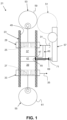
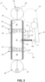
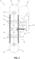
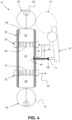
- a two-stroke, opposed-piston engine 21 is seen in FIGS. 1-4 and comprises a cylinder 23 including an inlet port 25 and an exhaust port 27.
- the inlet port 25 and the exhaust port 27 are typically in the form of a plurality of openings in the cylinder wall.
- the openings are typically elongated in a direction of a longitudinal axis of the cylinder 23.
- the inlet port 25 typically leads to an inlet gallery 29 in flow communication with a charge air channel 31.
- a compressor of a turbocharger (not shown) and a supercharger or other form of blower (not shown), and one or more charge air coolers (not shown) are typically disposed upstream of the inlet gallery 29 to provide pressurized air to facilitate scavenging of the cylinder 23.
- the exhaust port 27 typically leads to an exhaust gallery 33 in flow communication with an exhaust channel 35.
- a turbine of a turbocharger (not shown), an exhaust gas recirculation line (not shown) that connects to the charge air channel 31 are typically disposed downstream of the exhaust gallery 33, along with other exhaust aftertreatment devices (not shown) such as a diesel particulate filter, and a selective catalyst reduction catalyst.
- An inlet piston 37 is movable in the cylinder 23 between an inlet piston top dead center (IPTDC) position ( FIGS. 1 and 3 ) and an inlet piston bottom dead center (IPDBC) position ( FIGS. 2 and 4 ), and an exhaust piston 39 is movable in the cylinder between an exhaust piston top dead center (OPTDC) position ( FIGS. 1 and 3 ) and an exhaust piston bottom dead center (OPBDC) position ( FIGS. 2 and 4 ).
- the inlet piston 37 permits flow communication between the inlet port 25 and a combustion chamber 41 defined by the cylinder 23, the inlet piston 37 when the inlet piston is in the IPBDC position and blocks flow communication between the inlet port and the combustion chamber when the inlet piston is in the IPTDC position.
- the exhaust piston 39 permits flow communication between the exhaust port 27 and the combustion chamber 41 when the exhaust piston is in the OPBDC position and blocking flow communication between the exhaust port and the combustion chamber when the exhaust piston is in the OPTDC position.
- the inlet piston 37 and the exhaust piston will completely block the inlet port 25 and the exhaust port 27, respectively, at some point well before and after the IPDBC and OPDBC positions. While FIGS. 1-4 show the inlet piston 37 and the exhaust piston 39 being in their respective top dead center positions and bottom dead center positions at the same time, the movement of the pistons will often be timed so that the exhaust port 27 opens before the inlet port 25 opens and closes before the inlet port closes. In this way, pressurized combustion gases in the combustion chamber 41, and the exhaust piston 39 will start exiting the cylinder through the exhaust port 27 before charge air starts entering the cylinder through the inlet port 25 and further forces the combustion gases out of the cylinder, facilitating uniflow scavenging.
- a conduit 43 extends directly from the combustion chamber 41 to the charge air channel 31.
- the conduit 43 extends directly from the combustion chamber 41 to the charge air channel 31 in the sense that there is no intermediate structure between the combustion chamber and the charge air channel, e.g., the conduit does not first open to the exhaust channel 35 or some kind of accumulator.
- a valve 45 is arranged to selectively open and close flow communication through the conduit 43.
- selectively opening and closing it is intended to refer to opening and closing under control of an operator or a suitable controller (e.g., an ECU) programmed to open and close flow communication under particular circumstances, as opposed to opening and closing that occurs randomly or at all times.
- a compression release brake function is provided by selectively opening flow communication through the conduit 43 via the valve 45.
- the valve 45 is ordinarily a poppet valve arranged to open and close port 47 in the wall 49 of the cylinder 23 that leads to the conduit 43, however, the valve may be another form of valve that closes the conduit itself.
- a spring (not shown) will ordinarily be provided to urge a poppet or other form of valve 45 to a closed position as seen in FIGS. 1 , 2 , and 4 .
- the valve 45 is arranged to selectively open and close flow communication through the conduit 43 only when the inlet piston 37 and the exhaust piston 39 are both in positions in which flow communication between the combustion chamber 41 and both the inlet port 25 and the exhaust port 27 is blocked by the inlet piston and the exhaust piston, respectively.
- the valve 45 is arranged to selectively open and close flow communication through the conduit 43 via a gear and camshaft arrangement 51 driven by one or both of an inlet crankshaft 53 driven by the inlet piston 37 and an exhaust crankshaft 55 driven by the exhaust piston 39, where the gear and camshaft arrangement in turn drives a rocker arm 57 that pivots to open and close the valve.
- the valve 45 is arranged to selectively open and close flow communication through the conduit 43 via hydraulic, pneumatic, or electronic drives (not shown) that can be controlled by an operator or a controller such as an ECU.
- At least one of the inlet crankshaft 53 includes an inlet crank gear 59 and the exhaust crankshaft 55 can include an exhaust crank gear 61.
- a camshaft 63 includes a cam drive gear 65 driven by the at least one of the inlet crank gear 59 and the exhaust crank gear 61, and a cam 67 on the camshaft arranged to drive the rocker arm 57 to move the valve 45 to permit selective opening and closing of flow communication through the conduit 43 by the valve.
- Idler gears (not shown) will typically be disposed between gears mounted on the inlet crankshaft 53 and/or the exhaust crankshaft 55 such as the inlet crank gear 59 and/or the exhaust crank gear 61.
- the rocker arm 57 comprises a surface 69 that contacts the valve 45 to move it between an extended position and a retracted position (shown in phantom in FIG. 5 ) as the cam 67 rotates.
- the rocker arm surface 69 that contacts the valve 45 is a surface of a rocker arm piston 71 that is movable outwardly from a first position (shown in phantom in FIG. 5 ) to a second position.
- Rocker arms with movable pistons for opening valves in engines suitable or adaptable for use in connection with the present invention are disclosed in, e.g., U.S. Patent No. 8,151,749 and U.S. App. Pub. US2013/0220249 .
- a valve 45 arranged with a gear and camshaft arrangement 51 such as shown in FIG. 5 permits flow communication through the conduit 43 only when the rocker arm piston 71 is at least partially moved away from the first position toward the second position.
- the rocker arm piston 71 is any one of hydraulically driven, pneumatically driven, or electrically driven (e.g., via a solenoid) between the first and second positions.
- the rocker arm 57 can be connected to a source 73 (shown in phantom) of hydraulic or pneumatic fluid or electrical power. As seen in FIG. 6 , the rocker arm piston 71 is moved to positions between the first and second positions so that the degree of opening of the conduit 43 by the valve 45 can be increased or decreased as desired to vary the compression release brake function achieved.
- a method aspect of the invention involves operating a two-stroke, opposed-piston engine 21 that comprises a cylinder 23 with an inlet piston 37 controlled inlet port 25 and an exhaust piston 39 controlled exhaust port 27.
- the cylinder 23 defines a combustion chamber 41 with the inlet piston 37 and the exhaust piston 39.
- a charge air channel 31 is in flow communication with the inlet port 25.
- the method comprises selectively opening ( FIG. 3 ) and closing ( FIGS. 1 , 2 , and 4 ) flow communication through a conduit 43 extending directly from the combustion chamber 41 to the charge air channel 31.
- conduit 43 flow communication through the conduit 43 will be selectively opened and closed only when the inlet piston 37 and the exhaust piston 39 are both in positions in which flow communication between the combustion chamber 41 and both the inlet port 25 and the exhaust port 27 is blocked.
- the engine 21 comprises an inlet crankshaft 55 driven by the inlet piston 37 and an exhaust crankshaft 57 driven by the exhaust piston 39, and at least one of the inlet crankshaft includes an inlet crank gear 59 and the exhaust crankshaft includes an exhaust crank gear 51.
- a camshaft 63 including a cam drive gear 65 driven by the at least one of the inlet crank gear 59 and the exhaust crank gear 61, and a cam 67on the camshaft arranged to drive a rocker arm 57 to move a valve 45 to permit the selective opening and closing of flow communication through the conduit 43.
- the rocker arm 57 comprises a surface 69 that contacts the valve 45 to move it between an extended position ( FIG. 3 ) and a retracted position ( FIGS.
- the rocker arm surface 69 that contacts the valve 45 is a surface of a rocker arm piston 71 that is movable outwardly from a first position ( FIGS. 1 and 2 ) to a second position ( FIGS. 3 and 4 ).
- the valve 45 ordinarily permits flow communication through the conduit 43 only when the rocker arm piston 71 is at least partially moved away from the first position toward the second position.
- the method comprises selectively moving the rocker arm piston between the first and second position, e.g., to perform a compression release braking function in response to an operator or controller generated command.
- the valve 45 is movable between a fully closed position ( FIGS. 1 , 2 , and 4 ) in which flow communication through the conduit 43 is completely blocked and a fully open position ( FIG. 3 ) in which flow communication through the conduit is unobstructed by the valve, and to one or more partially open positions ( FIG. 6 ) in which flow communication through the conduit is partially obstructed by the valve.
- the method further comprises holding the rocker arm piston 71 in an intermediate position ( FIG. 6 ) between the first position and the second position so that the valve 45 is in one of one or more partially open positions.
- the rocker arm piston 71 can further be moved between the intermediate position ( FIG. 6 ) and the second position in which the valve 45 is positioned so that the conduit 43 is fully open ( FIG. 5 ,solid lines) or the first position in which the valve is positioned so that the conduit is fully closed.
- any actuators used to open and close flow communication through the conduit can be kept in a cooler environment. Additionally, noise from the compression release brake operation is muted because the compression release is not directly into the exhaust system. Further, heat dissipation from the brake operation is handled during the scavenge event of the two stroke engine.
Landscapes
- Engineering & Computer Science (AREA)
- Mechanical Engineering (AREA)
- General Engineering & Computer Science (AREA)
- Chemical & Material Sciences (AREA)
- Combustion & Propulsion (AREA)
- Valve Device For Special Equipments (AREA)
Claims (4)
- Zweitaktmotor mit gegenüberliegenden Kolben (21), umfassend:einen Zylinder (23) mit einer von einem Einlasskolben (37) gesteuerten Einlassöffnung (25) und einer von einem Auslasskolben (39) gesteuerten Auslassöffnung (27), wobei der Zylinder eine Verbrennungskammer mit dem Einlasskolben und dem Auslasskolben definiert;einen Ladeluftkanal (31) in Strömungsverbindung mit der Einlassöffnung;eine Leitung (43), die sich von der Verbrennungskammer (41) zum Ladeluftkanal erstreckt;ein Ventil (45), das angeordnet ist, um die Strömungsverbindung durch die Leitung selektiv zu öffnen und zu schließen, wobei das Ventil (45) angeordnet ist, um die Strömungsverbindung durch die Leitung nur dann selektiv zu öffnen und zu schließen, wenn der Einlasskolben und der Auslasskolben sich beide in Positionen befinden, in denen die Strömungsverbindung zwischen der Verbrennungskammer und sowohl der Einlassöffnung als auch der Auslassöffnung blockiert ist, undeine Steuerung, die konfiguriert ist, zum:Bereitstellen einer Kompressionsentlastungs-Bremsfunktion durch Öffnen des Ventils (45),eine Einlasskurbelwelle (53), die durch den Einlasskolben angetrieben wird, und eine Auslasskurbelwelle (55), die durch den Auslasskolben angetrieben wird, mindestens eine Einlasskurbelwelle mit einem Einlasskurbelgetriebe oder eine Auslasskurbelwelle mit einem Auslasskurbelgetriebe, eine Nockenwelle mit einem Nockenantriebsgetriebe, das durch das mindestens eine Einlasskurbelgetriebe oder das Auslasskurbelgetriebe angetrieben wird, und einen Nocken auf der Nockenwelle, der so angeordnet ist, dass er einen Kipphebel (57) antreibt, um das Ventil zu bewegen, um ein selektives Öffnen und Schließen der Strömungsverbindung durch die Leitung durch das Ventil zu ermöglichen,wobei der Kipphebel eine Oberfläche umfasst, die das Ventil berührt, um es zwischen einer ausgefahrenen Position und einer eingefahrenen Position zu bewegen, wenn sich der Nocken dreht,wobei die Kipphebeloberfläche (69), die das Ventil berührt, eine Oberfläche eines Kipphebelkolbens ist, der nach außen von einer ersten Position in eine zweite Position bewegbar ist, wobei das Ventil nur dann eine Strömungsverbindung durch die Leitung zulässt, wenn der Kipphebelkolben mindestens teilweise von der ersten Position weg in Richtung der zweiten Position bewegt wird,wobei das Ventil zwischen einer vollständig geschlossenen Position, in der die Strömungsverbindung durch die Leitung vollständig blockiert ist, und einer vollständig geöffneten Position, in der die Strömungsverbindung durch die Leitung nicht durch das Ventil behindert ist, und in eine oder mehrere teilweise geöffnete Positionen, in denen die Strömungsverbindung durch die Leitung teilweise durch das Ventil behindert ist, bewegbar ist, wobei der Kipphebelkolben entweder hydraulisch, pneumatisch oder elektrisch zwischen der ersten und der zweiten Position und in eine Zwischenposition zwischen der ersten Position und der zweiten Position angetrieben wird, so dass sich das Ventil in einer der einen oder mehreren teilweise offenen Positionen befindet.
- Motor nach Anspruch 1, wobei das Ventil ein Tellerventil ist.
- Verfahren zum Betrieb eines Zweitaktmotors mit gegenüberliegenden Kolben (21), wobei der Motor einen Zylinder (23) mit einer von einem Einlasskolben (37) gesteuerten Einlassöffnung (25) und einer von einem Auslasskolben (39) gesteuerten Auslassöffnung (27) umfasst, wobei der Zylinder eine Verbrennungskammer mit dem Einlasskolben und dem Auslasskolben und einen Ladeluftkanal (31) in Strömungsverbindung mit der Einlassöffnung definiert, das Verfahren umfassend:Bereitstellen einer Kompressionsentlastungs-Bremsfunktion durch selektives Öffnen und Schließen der Strömungsverbindung durch eine Leitung, die sich von der Verbrennungskammer zum Ladeluftkanal erstreckt, indem ein Ventil (45) zwischen einer offenen und einer geschlossenen Position bewegt wird; undselektives Öffnen und Schließen der Strömungsverbindung durch die Leitung nur dann, wenn der Einlasskolben und der Auslasskolben beide in Positionen sind, in denen die Strömungsverbindung zwischen der Verbrennungskammer und sowohl der Einlassöffnung als auch der Auslassöffnung blockiert ist; undwobei der Motor eine Einlasskurbelwelle, die durch den Einlasskolben angetrieben wird, und eine Auslasskurbelwelle, die durch den Auslasskolben angetrieben wird, mindestens eine Einlasskurbelwelle mit einem Einlasskurbelgetriebe oder Auslasskurbelwelle mit einem Auslasskurbelgetriebe, eine Nockenwelle mit einem Nockenantriebsgetriebe, das durch das mindestens eine Einlasskurbelgetriebe oder das Auslasskurbelgetriebe angetrieben wird, und einen Nocken auf der Nockenwelle umfasst, der so angeordnet ist, dass er einen Kipphebel antreibt, um das Ventil zu bewegen, um ein selektives Öffnen und Schließen der Strömungsverbindung durch die Leitung durch das Ventil zu ermöglichen,wobei der Kipphebel eine Oberfläche aufweist, die das Ventil berührt, um es zwischen einer ausgefahrenen Position und einer eingefahrenen Position zu bewegen, wenn sich der Nocken dreht, wobei die Kipphebeloberfläche, die das Ventil berührt, eine Oberfläche eines Kipphebelkolbens ist, der von einer ersten Position zu einer zweiten Position nach außen bewegbar ist, wobei das Ventil nur dann eine Strömungsverbindung durch die Leitung zulässt, wenn der Kipphebelkolben mindestens teilweise von der ersten Position in Richtung der zweiten Position bewegt wird, wobei das Verfahren ein selektives Bewegen des Kipphebelkolbens zwischen der ersten und der zweiten Position umfasst,wobei das Ventil zwischen einer vollständig geschlossenen Position, in der die Strömungsverbindung durch die Leitung vollständig blockiert ist, und einer vollständig geöffneten Position, in der die Strömungsverbindung durch die Leitung nicht durch das Ventil behindert ist, und in eine oder mehrere teilweise geöffnete Positionen, in denen die Strömungsverbindung durch die Leitung teilweise durch das Ventil behindert ist, bewegbar ist, wobei das Verfahren das Halten des Kipphebelkolbens in einer Zwischenposition zwischen der ersten Position und der zweiten Position umfasst, so dass sich das Ventil in einer der einen oder mehreren teilweise offenen Positionen befindet.
- Verfahren nach Anspruch 3, umfassend das Bewegen des Kipphebelkolbens zwischen der Zwischenposition und der vollständig geöffneten Position.
Applications Claiming Priority (1)
| Application Number | Priority Date | Filing Date | Title |
|---|---|---|---|
| PCT/US2014/058107 WO2016053256A1 (en) | 2014-09-29 | 2014-09-29 | Two-stroke, opposed-piston engine with compression release |
Publications (3)
| Publication Number | Publication Date |
|---|---|
| EP3201447A1 EP3201447A1 (de) | 2017-08-09 |
| EP3201447A4 EP3201447A4 (de) | 2018-04-11 |
| EP3201447B1 true EP3201447B1 (de) | 2023-05-31 |
Family
ID=55631113
Family Applications (1)
| Application Number | Title | Priority Date | Filing Date |
|---|---|---|---|
| EP14903309.4A Active EP3201447B1 (de) | 2014-09-29 | 2014-09-29 | Zweitaktmotor mit gegenüberliegenden kolben mit kompressionsentlastung |
Country Status (4)
| Country | Link |
|---|---|
| US (1) | US10683782B2 (de) |
| EP (1) | EP3201447B1 (de) |
| CN (1) | CN107076008B (de) |
| WO (1) | WO2016053256A1 (de) |
Families Citing this family (1)
| Publication number | Priority date | Publication date | Assignee | Title |
|---|---|---|---|---|
| CN112005000B (zh) * | 2018-04-16 | 2022-06-21 | 沃尔沃卡车集团 | 内燃发动机装置 |
Family Cites Families (24)
| Publication number | Priority date | Publication date | Assignee | Title |
|---|---|---|---|---|
| DE482085C (de) | 1927-01-09 | 1929-09-14 | Sun Shipbuilding & Dry Dock Co | Verfahren und Vorrichtung zum Bremsen von Brennkraftmaschinen, bei denen eine Mehrzahl von Arbeitszylindern vorhanden ist, die Verdichtungschuebe nicht gleichzeitig stattfinden und das verdichtete Gas oder die Luft oder beide aus einem Zylinder in den andern uebergefuehrt werden |
| US3547087A (en) | 1968-08-09 | 1970-12-15 | White Motor Corp | Engine valve control for braking operation |
| US6279520B1 (en) * | 1996-04-15 | 2001-08-28 | Alvin Lowi, Jr. | Adiabatic, two-stroke cycle engine having novel scavenge compressor arrangement |
| US6000374A (en) * | 1997-12-23 | 1999-12-14 | Diesel Engine Retarders, Inc. | Multi-cycle, engine braking with positive power valve actuation control system and process for using the same |
| US6209495B1 (en) | 1999-04-02 | 2001-04-03 | Walter Warren | Compound two stroke engine |
| GB2364745A (en) * | 2000-07-14 | 2002-02-06 | Jonathan Austin Ma | Camshaft drive system for selectable two-stroke/ four-stroke i.c. engine |
| WO2002006639A1 (en) | 2000-07-14 | 2002-01-24 | Ma (Innovation) 2T4 Limited | Selectable 2 stroke / 4 stoke camshaft drive system |
| US6668809B2 (en) * | 2001-11-19 | 2003-12-30 | Alvin Lowi, Jr. | Stationary regenerator, regenerated, reciprocating engine |
| US6779494B1 (en) | 2003-06-18 | 2004-08-24 | Deepak Jayanti Aswani | Balanced barrel-cam internal-combustion engine |
| US6959672B1 (en) | 2004-05-25 | 2005-11-01 | Ford Global Technologies, Llc | Fuel injection for a free piston engine |
| EP2041464B1 (de) | 2006-07-10 | 2012-07-04 | Mack Trucks, Inc. | Hin und her gehendes glied mit schwimmschutzanordnung |
| EP2092167B1 (de) | 2006-12-12 | 2013-02-27 | Mack Trucks, Inc. | Ventilöffnungsanordnung und -verfahren |
| US7779795B2 (en) | 2008-01-09 | 2010-08-24 | Warren James C | Valve system for opposed piston engines |
| CN101960088B (zh) | 2008-01-11 | 2013-08-21 | 迈克梵航空有限责任公司 | 往复式内燃机 |
| US8485161B2 (en) | 2008-09-04 | 2013-07-16 | Achates Power, Inc. | Opposed piston, compression ignition engine with single-side mounted crankshafts and crossheads |
| US8397685B2 (en) | 2010-04-21 | 2013-03-19 | Motiv Engines, LLC | Fuel injection system |
| US8549854B2 (en) | 2010-05-18 | 2013-10-08 | Achates Power, Inc. | EGR constructions for opposed-piston engines |
| WO2012067643A1 (en) * | 2010-11-15 | 2012-05-24 | Achates Power, Inc. | Two stroke opposed-piston engines with compression release for engine braking |
| AU2010363967B2 (en) | 2010-11-17 | 2016-02-11 | Volvo Truck Corporation | Hinged rocker arm and valve opening arrangement including a hinged rocker arm |
| WO2013058802A1 (en) * | 2011-02-23 | 2013-04-25 | Achates Power Inc. | Two stroke, opposed-piston engines with engine braking |
| EP2677141A1 (de) | 2012-06-21 | 2013-12-25 | Wärtsilä Schweiz AG | Verfahren zum Betreiben eines Zweitakt-Grossdieselmotors sowie Zweitakt-Grossdieselmotor |
| DE202013002671U1 (de) | 2013-03-20 | 2013-04-15 | Günter Elsbett | Gaswechselsteuerung von Verbrennungsmotoren mit hydraulisch betätigten Gaswechselorganen |
| CN203271850U (zh) | 2013-06-08 | 2013-11-06 | 深圳市特尔佳科技股份有限公司 | 一种发动机压缩释放式制动器 |
| US10690051B2 (en) | 2014-06-16 | 2020-06-23 | Volvo Truck Corporation | Two-stroke opposed piston internal combustion engine |
-
2014
- 2014-09-29 CN CN201480082308.3A patent/CN107076008B/zh active Active
- 2014-09-29 US US15/512,561 patent/US10683782B2/en active Active
- 2014-09-29 WO PCT/US2014/058107 patent/WO2016053256A1/en not_active Ceased
- 2014-09-29 EP EP14903309.4A patent/EP3201447B1/de active Active
Also Published As
| Publication number | Publication date |
|---|---|
| EP3201447A1 (de) | 2017-08-09 |
| CN107076008B (zh) | 2020-12-01 |
| US20170218799A1 (en) | 2017-08-03 |
| EP3201447A4 (de) | 2018-04-11 |
| CN107076008A (zh) | 2017-08-18 |
| WO2016053256A1 (en) | 2016-04-07 |
| US10683782B2 (en) | 2020-06-16 |
Similar Documents
| Publication | Publication Date | Title |
|---|---|---|
| EP1472440B1 (de) | Effizientes ventilbetätigungsglied für verbrennungsmotor | |
| KR20090016698A (ko) | 엔진 브레이크 작동 방법 | |
| KR20050054942A (ko) | 내적 배기 가스 재순환 시스템 및 방법 | |
| WO2007042876A3 (en) | Control device and method for internal combustion engine | |
| US7472696B2 (en) | Exhaust gas recirculation system with in-cylinder valve actuation | |
| JP2011149428A (ja) | 部分負荷の下で動作している直噴で過給式の多気筒内燃エンジンの残留燃焼ガス掃気方法 | |
| JP6671462B2 (ja) | 混合排気および圧縮解放エンジンブレーキのための方法および装置 | |
| US20160160710A1 (en) | Engine braking via advancing the exhaust valve | |
| EP2941547A1 (de) | Ventilhebeanordnung und verfahren zum betrieb einer ventilhebeeinrichtung | |
| CN104822911B (zh) | 气体交换阀装置 | |
| EP2077380B1 (de) | Ventilgesteuerte Partikelfilter Regenerationsvorrichtung | |
| US10683782B2 (en) | Two stroke, opposed piston engine with compression release brake arrangement and method | |
| CN101519985B (zh) | 用于带有凸轮轴的大型二冲程柴油发动机的可变气门正时 | |
| Jia et al. | Compression-release engine brake modeling and braking performance simulation | |
| CN116892430A (zh) | 用于内燃发动机的间隙调整和停缸的系统和方法 | |
| JP5909954B2 (ja) | 内燃機関の過給補助システム、内燃機関、及び内燃機関の過給補助方法 | |
| CN107218127B (zh) | 一种四汽缸自增压发动机 | |
| EP1920143B1 (de) | Steuerverfahren für die einlass- und auslassventile eines motors und solche ventile umfassender verbrennungsmotor | |
| EP3698030B1 (de) | Verfahren in einem zweitaktmotor und zweitaktmotor | |
| RU2566856C1 (ru) | Способ привода клапанов трёхклапанного газораспределителя двигателя внутреннего сгорания пневматической системой привода с зарядкой пневмоаккумулятора системы привода атмосферным воздухом | |
| US8943822B2 (en) | Engine system having dedicated auxiliary connection to cylinder | |
| CN111655982B (zh) | 用于控制连杆轴承的润滑的方法 | |
| US20120023916A1 (en) | Diesel CGR process and structure | |
| JP6035989B2 (ja) | 圧縮開放ブレーキ装置 | |
| TR201701294A2 (tr) | Bi̇r supap kontrol mekani̇zmasi |
Legal Events
| Date | Code | Title | Description |
|---|---|---|---|
| STAA | Information on the status of an ep patent application or granted ep patent |
Free format text: STATUS: THE INTERNATIONAL PUBLICATION HAS BEEN MADE |
|
| PUAI | Public reference made under article 153(3) epc to a published international application that has entered the european phase |
Free format text: ORIGINAL CODE: 0009012 |
|
| STAA | Information on the status of an ep patent application or granted ep patent |
Free format text: STATUS: REQUEST FOR EXAMINATION WAS MADE |
|
| 17P | Request for examination filed |
Effective date: 20170428 |
|
| AK | Designated contracting states |
Kind code of ref document: A1 Designated state(s): AL AT BE BG CH CY CZ DE DK EE ES FI FR GB GR HR HU IE IS IT LI LT LU LV MC MK MT NL NO PL PT RO RS SE SI SK SM TR |
|
| AX | Request for extension of the european patent |
Extension state: BA ME |
|
| DAX | Request for extension of the european patent (deleted) | ||
| A4 | Supplementary search report drawn up and despatched |
Effective date: 20180314 |
|
| RIC1 | Information provided on ipc code assigned before grant |
Ipc: F02D 13/04 20060101ALI20180308BHEP Ipc: F02D 13/02 20060101ALI20180308BHEP Ipc: F01B 7/02 20060101ALI20180308BHEP Ipc: F02B 75/02 20060101ALI20180308BHEP Ipc: F01L 13/08 20060101ALI20180308BHEP Ipc: F02B 75/28 20060101ALI20180308BHEP Ipc: F02B 25/08 20060101AFI20180308BHEP Ipc: F01L 13/06 20060101ALI20180308BHEP Ipc: F01L 13/00 20060101ALI20180308BHEP Ipc: F01L 1/18 20060101ALI20180308BHEP Ipc: F01L 1/047 20060101ALI20180308BHEP |
|
| STAA | Information on the status of an ep patent application or granted ep patent |
Free format text: STATUS: EXAMINATION IS IN PROGRESS |
|
| 17Q | First examination report despatched |
Effective date: 20200115 |
|
| GRAP | Despatch of communication of intention to grant a patent |
Free format text: ORIGINAL CODE: EPIDOSNIGR1 |
|
| STAA | Information on the status of an ep patent application or granted ep patent |
Free format text: STATUS: GRANT OF PATENT IS INTENDED |
|
| RIC1 | Information provided on ipc code assigned before grant |
Ipc: F01L 3/00 20060101ALN20221114BHEP Ipc: F01L 1/12 20060101ALI20221114BHEP Ipc: F01B 7/14 20060101ALI20221114BHEP Ipc: F02B 75/28 20060101ALI20221114BHEP Ipc: F01L 13/06 20060101ALI20221114BHEP Ipc: F01L 13/08 20060101ALI20221114BHEP Ipc: F01B 7/02 20060101ALI20221114BHEP Ipc: F02D 13/02 20060101ALI20221114BHEP Ipc: F02D 13/04 20060101ALI20221114BHEP Ipc: F01L 1/047 20060101ALI20221114BHEP Ipc: F01L 1/18 20060101ALI20221114BHEP Ipc: F01L 13/00 20060101ALI20221114BHEP Ipc: F02B 75/02 20060101ALI20221114BHEP Ipc: F02B 25/08 20060101AFI20221114BHEP |
|
| RIC1 | Information provided on ipc code assigned before grant |
Ipc: F01L 3/00 20060101ALN20221208BHEP Ipc: F01L 1/12 20060101ALI20221208BHEP Ipc: F01B 7/14 20060101ALI20221208BHEP Ipc: F02B 75/28 20060101ALI20221208BHEP Ipc: F01L 13/06 20060101ALI20221208BHEP Ipc: F01L 13/08 20060101ALI20221208BHEP Ipc: F01B 7/02 20060101ALI20221208BHEP Ipc: F02D 13/02 20060101ALI20221208BHEP Ipc: F02D 13/04 20060101ALI20221208BHEP Ipc: F01L 1/047 20060101ALI20221208BHEP Ipc: F01L 1/18 20060101ALI20221208BHEP Ipc: F01L 13/00 20060101ALI20221208BHEP Ipc: F02B 75/02 20060101ALI20221208BHEP Ipc: F02B 25/08 20060101AFI20221208BHEP |
|
| INTG | Intention to grant announced |
Effective date: 20221220 |
|
| GRAS | Grant fee paid |
Free format text: ORIGINAL CODE: EPIDOSNIGR3 |
|
| GRAA | (expected) grant |
Free format text: ORIGINAL CODE: 0009210 |
|
| STAA | Information on the status of an ep patent application or granted ep patent |
Free format text: STATUS: THE PATENT HAS BEEN GRANTED |
|
| AK | Designated contracting states |
Kind code of ref document: B1 Designated state(s): AL AT BE BG CH CY CZ DE DK EE ES FI FR GB GR HR HU IE IS IT LI LT LU LV MC MK MT NL NO PL PT RO RS SE SI SK SM TR |
|
| REG | Reference to a national code |
Ref country code: GB Ref legal event code: FG4D Ref country code: CH Ref legal event code: EP |
|
| REG | Reference to a national code |
Ref country code: AT Ref legal event code: REF Ref document number: 1571041 Country of ref document: AT Kind code of ref document: T Effective date: 20230615 Ref country code: DE Ref legal event code: R096 Ref document number: 602014087095 Country of ref document: DE |
|
| REG | Reference to a national code |
Ref country code: IE Ref legal event code: FG4D |
|
| REG | Reference to a national code |
Ref country code: LT Ref legal event code: MG9D |
|
| REG | Reference to a national code |
Ref country code: NL Ref legal event code: MP Effective date: 20230531 |
|
| REG | Reference to a national code |
Ref country code: AT Ref legal event code: MK05 Ref document number: 1571041 Country of ref document: AT Kind code of ref document: T Effective date: 20230531 |
|
| PG25 | Lapsed in a contracting state [announced via postgrant information from national office to epo] |
Ref country code: SE Free format text: LAPSE BECAUSE OF FAILURE TO SUBMIT A TRANSLATION OF THE DESCRIPTION OR TO PAY THE FEE WITHIN THE PRESCRIBED TIME-LIMIT Effective date: 20230531 Ref country code: NO Free format text: LAPSE BECAUSE OF FAILURE TO SUBMIT A TRANSLATION OF THE DESCRIPTION OR TO PAY THE FEE WITHIN THE PRESCRIBED TIME-LIMIT Effective date: 20230831 Ref country code: ES Free format text: LAPSE BECAUSE OF FAILURE TO SUBMIT A TRANSLATION OF THE DESCRIPTION OR TO PAY THE FEE WITHIN THE PRESCRIBED TIME-LIMIT Effective date: 20230531 Ref country code: AT Free format text: LAPSE BECAUSE OF FAILURE TO SUBMIT A TRANSLATION OF THE DESCRIPTION OR TO PAY THE FEE WITHIN THE PRESCRIBED TIME-LIMIT Effective date: 20230531 |
|
| PG25 | Lapsed in a contracting state [announced via postgrant information from national office to epo] |
Ref country code: RS Free format text: LAPSE BECAUSE OF FAILURE TO SUBMIT A TRANSLATION OF THE DESCRIPTION OR TO PAY THE FEE WITHIN THE PRESCRIBED TIME-LIMIT Effective date: 20230531 Ref country code: PL Free format text: LAPSE BECAUSE OF FAILURE TO SUBMIT A TRANSLATION OF THE DESCRIPTION OR TO PAY THE FEE WITHIN THE PRESCRIBED TIME-LIMIT Effective date: 20230531 Ref country code: NL Free format text: LAPSE BECAUSE OF FAILURE TO SUBMIT A TRANSLATION OF THE DESCRIPTION OR TO PAY THE FEE WITHIN THE PRESCRIBED TIME-LIMIT Effective date: 20230531 Ref country code: LV Free format text: LAPSE BECAUSE OF FAILURE TO SUBMIT A TRANSLATION OF THE DESCRIPTION OR TO PAY THE FEE WITHIN THE PRESCRIBED TIME-LIMIT Effective date: 20230531 Ref country code: LT Free format text: LAPSE BECAUSE OF FAILURE TO SUBMIT A TRANSLATION OF THE DESCRIPTION OR TO PAY THE FEE WITHIN THE PRESCRIBED TIME-LIMIT Effective date: 20230531 Ref country code: IS Free format text: LAPSE BECAUSE OF FAILURE TO SUBMIT A TRANSLATION OF THE DESCRIPTION OR TO PAY THE FEE WITHIN THE PRESCRIBED TIME-LIMIT Effective date: 20230930 Ref country code: HR Free format text: LAPSE BECAUSE OF FAILURE TO SUBMIT A TRANSLATION OF THE DESCRIPTION OR TO PAY THE FEE WITHIN THE PRESCRIBED TIME-LIMIT Effective date: 20230531 Ref country code: GR Free format text: LAPSE BECAUSE OF FAILURE TO SUBMIT A TRANSLATION OF THE DESCRIPTION OR TO PAY THE FEE WITHIN THE PRESCRIBED TIME-LIMIT Effective date: 20230901 |
|
| PG25 | Lapsed in a contracting state [announced via postgrant information from national office to epo] |
Ref country code: FI Free format text: LAPSE BECAUSE OF FAILURE TO SUBMIT A TRANSLATION OF THE DESCRIPTION OR TO PAY THE FEE WITHIN THE PRESCRIBED TIME-LIMIT Effective date: 20230531 |
|
| PG25 | Lapsed in a contracting state [announced via postgrant information from national office to epo] |
Ref country code: SK Free format text: LAPSE BECAUSE OF FAILURE TO SUBMIT A TRANSLATION OF THE DESCRIPTION OR TO PAY THE FEE WITHIN THE PRESCRIBED TIME-LIMIT Effective date: 20230531 |
|
| PG25 | Lapsed in a contracting state [announced via postgrant information from national office to epo] |
Ref country code: SM Free format text: LAPSE BECAUSE OF FAILURE TO SUBMIT A TRANSLATION OF THE DESCRIPTION OR TO PAY THE FEE WITHIN THE PRESCRIBED TIME-LIMIT Effective date: 20230531 Ref country code: SK Free format text: LAPSE BECAUSE OF FAILURE TO SUBMIT A TRANSLATION OF THE DESCRIPTION OR TO PAY THE FEE WITHIN THE PRESCRIBED TIME-LIMIT Effective date: 20230531 Ref country code: RO Free format text: LAPSE BECAUSE OF FAILURE TO SUBMIT A TRANSLATION OF THE DESCRIPTION OR TO PAY THE FEE WITHIN THE PRESCRIBED TIME-LIMIT Effective date: 20230531 Ref country code: PT Free format text: LAPSE BECAUSE OF FAILURE TO SUBMIT A TRANSLATION OF THE DESCRIPTION OR TO PAY THE FEE WITHIN THE PRESCRIBED TIME-LIMIT Effective date: 20231002 Ref country code: EE Free format text: LAPSE BECAUSE OF FAILURE TO SUBMIT A TRANSLATION OF THE DESCRIPTION OR TO PAY THE FEE WITHIN THE PRESCRIBED TIME-LIMIT Effective date: 20230531 Ref country code: DK Free format text: LAPSE BECAUSE OF FAILURE TO SUBMIT A TRANSLATION OF THE DESCRIPTION OR TO PAY THE FEE WITHIN THE PRESCRIBED TIME-LIMIT Effective date: 20230531 Ref country code: CZ Free format text: LAPSE BECAUSE OF FAILURE TO SUBMIT A TRANSLATION OF THE DESCRIPTION OR TO PAY THE FEE WITHIN THE PRESCRIBED TIME-LIMIT Effective date: 20230531 |
|
| REG | Reference to a national code |
Ref country code: DE Ref legal event code: R097 Ref document number: 602014087095 Country of ref document: DE |
|
| PLBE | No opposition filed within time limit |
Free format text: ORIGINAL CODE: 0009261 |
|
| STAA | Information on the status of an ep patent application or granted ep patent |
Free format text: STATUS: NO OPPOSITION FILED WITHIN TIME LIMIT |
|
| REG | Reference to a national code |
Ref country code: CH Ref legal event code: PL |
|
| PG25 | Lapsed in a contracting state [announced via postgrant information from national office to epo] |
Ref country code: SI Free format text: LAPSE BECAUSE OF FAILURE TO SUBMIT A TRANSLATION OF THE DESCRIPTION OR TO PAY THE FEE WITHIN THE PRESCRIBED TIME-LIMIT Effective date: 20230531 |
|
| 26N | No opposition filed |
Effective date: 20240301 |
|
| PG25 | Lapsed in a contracting state [announced via postgrant information from national office to epo] |
Ref country code: LU Free format text: LAPSE BECAUSE OF NON-PAYMENT OF DUE FEES Effective date: 20230929 |
|
| REG | Reference to a national code |
Ref country code: BE Ref legal event code: MM Effective date: 20230930 |
|
| GBPC | Gb: european patent ceased through non-payment of renewal fee |
Effective date: 20230929 |
|
| PG25 | Lapsed in a contracting state [announced via postgrant information from national office to epo] |
Ref country code: SI Free format text: LAPSE BECAUSE OF FAILURE TO SUBMIT A TRANSLATION OF THE DESCRIPTION OR TO PAY THE FEE WITHIN THE PRESCRIBED TIME-LIMIT Effective date: 20230531 Ref country code: LU Free format text: LAPSE BECAUSE OF NON-PAYMENT OF DUE FEES Effective date: 20230929 Ref country code: IT Free format text: LAPSE BECAUSE OF FAILURE TO SUBMIT A TRANSLATION OF THE DESCRIPTION OR TO PAY THE FEE WITHIN THE PRESCRIBED TIME-LIMIT Effective date: 20230531 Ref country code: MC Free format text: LAPSE BECAUSE OF FAILURE TO SUBMIT A TRANSLATION OF THE DESCRIPTION OR TO PAY THE FEE WITHIN THE PRESCRIBED TIME-LIMIT Effective date: 20230531 |
|
| REG | Reference to a national code |
Ref country code: IE Ref legal event code: MM4A |
|
| PG25 | Lapsed in a contracting state [announced via postgrant information from national office to epo] |
Ref country code: IE Free format text: LAPSE BECAUSE OF NON-PAYMENT OF DUE FEES Effective date: 20230929 |
|
| PG25 | Lapsed in a contracting state [announced via postgrant information from national office to epo] |
Ref country code: GB Free format text: LAPSE BECAUSE OF NON-PAYMENT OF DUE FEES Effective date: 20230929 |
|
| PG25 | Lapsed in a contracting state [announced via postgrant information from national office to epo] |
Ref country code: CH Free format text: LAPSE BECAUSE OF NON-PAYMENT OF DUE FEES Effective date: 20230930 |
|
| PG25 | Lapsed in a contracting state [announced via postgrant information from national office to epo] |
Ref country code: IE Free format text: LAPSE BECAUSE OF NON-PAYMENT OF DUE FEES Effective date: 20230929 Ref country code: GB Free format text: LAPSE BECAUSE OF NON-PAYMENT OF DUE FEES Effective date: 20230929 Ref country code: FR Free format text: LAPSE BECAUSE OF NON-PAYMENT OF DUE FEES Effective date: 20230930 Ref country code: CH Free format text: LAPSE BECAUSE OF NON-PAYMENT OF DUE FEES Effective date: 20230930 |
|
| PG25 | Lapsed in a contracting state [announced via postgrant information from national office to epo] |
Ref country code: BE Free format text: LAPSE BECAUSE OF NON-PAYMENT OF DUE FEES Effective date: 20230930 |
|
| PG25 | Lapsed in a contracting state [announced via postgrant information from national office to epo] |
Ref country code: BG Free format text: LAPSE BECAUSE OF FAILURE TO SUBMIT A TRANSLATION OF THE DESCRIPTION OR TO PAY THE FEE WITHIN THE PRESCRIBED TIME-LIMIT Effective date: 20230531 |
|
| PG25 | Lapsed in a contracting state [announced via postgrant information from national office to epo] |
Ref country code: BG Free format text: LAPSE BECAUSE OF FAILURE TO SUBMIT A TRANSLATION OF THE DESCRIPTION OR TO PAY THE FEE WITHIN THE PRESCRIBED TIME-LIMIT Effective date: 20230531 |
|
| PG25 | Lapsed in a contracting state [announced via postgrant information from national office to epo] |
Ref country code: CY Free format text: LAPSE BECAUSE OF FAILURE TO SUBMIT A TRANSLATION OF THE DESCRIPTION OR TO PAY THE FEE WITHIN THE PRESCRIBED TIME-LIMIT; INVALID AB INITIO Effective date: 20140929 |
|
| PG25 | Lapsed in a contracting state [announced via postgrant information from national office to epo] |
Ref country code: HU Free format text: LAPSE BECAUSE OF FAILURE TO SUBMIT A TRANSLATION OF THE DESCRIPTION OR TO PAY THE FEE WITHIN THE PRESCRIBED TIME-LIMIT; INVALID AB INITIO Effective date: 20140929 |
|
| PGFP | Annual fee paid to national office [announced via postgrant information from national office to epo] |
Ref country code: DE Payment date: 20250926 Year of fee payment: 12 |
|
| PG25 | Lapsed in a contracting state [announced via postgrant information from national office to epo] |
Ref country code: TR Free format text: LAPSE BECAUSE OF FAILURE TO SUBMIT A TRANSLATION OF THE DESCRIPTION OR TO PAY THE FEE WITHIN THE PRESCRIBED TIME-LIMIT Effective date: 20230531 |